Abstract
This paper systematically reviews research progress in semi-active suspension systems for agricultural machinery seats, focusing on key technologies and methods to enhance ride comfort. First, through an analysis of the comfort evaluation indicators and constraints of seat suspension systems, the current applications of variable stiffness and damping components, as well as semi-active control technologies, are outlined. Second, a comparative analysis of single control methods (such as PID control, fuzzy control, and sliding mode control) and composite control methods (such as fuzzy PID control, intelligent algorithm-based integrated control, and fuzzy sliding mode control) is conducted, with control mechanisms explained using principle block diagrams. Furthermore, key technical challenges in current research are summarized, including dynamic characteristic optimization design, adaptability to complex operating environments, and the robustness of control algorithms. Further research could explore the refinement of composite control strategies, the integrated application of intelligent materials, and the development of intelligent vibration damping technologies. This paper provides theoretical references for the optimization design and engineering practice of agricultural machinery suspension systems.
1. Introduction
With the continuous advancement of global agricultural modernization, agricultural machinery has become increasingly vital in enhancing operational efficiency, reducing labor intensity, and increasing crop yields. In modern agricultural production, large-scale machinery such as tractors and combine harvesters are widely used in plowing, planting, and harvesting. While these machines have significantly improved productivity, the complex working environments, prolonged operation hours, and intense vibrations pose severe challenges to the health and comfort of operators.
When the body is supported on a vibrating surface, that is, sitting, standing, or lying on a vibrating surface, a whole-body vibration (WBV) is generated [1]. The harsh, complex, and variable working conditions of agricultural machinery expose operators to low-frequency, high-intensity WBV over long periods. This not only causes fatigue and reduces operational efficiency but can also lead to serious health risks and discomfort [2]. Studies have shown that workers frequently exposed to low-frequency vibrations are at a higher risk of developing various health issues, including degenerative spinal diseases, motion sickness, fatigue, back pain, digestive problems, vision impairment, and even certain cancers (e.g., prostate cancer). Short-term impacts include reduced reaction times and impaired balance [3,4,5,6,7,8]. Figure 1 illustrates the effects of WBV on human health [3]. Prolonged exposure to low-frequency vibrations not only diminishes work efficiency but also severely affects the operator’s physical health and workplace comfort. Consequently, improving the comfort of agricultural machinery, particularly enhancing the vibration isolation performance of seats, has become a significant research focus in the field of agricultural engineering.
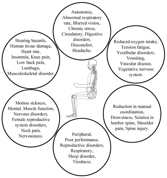
Figure 1.
Effects of whole-body vibration on human health [3].
The seat suspension, as the final link in the vibration transmission path, plays a critical role in connecting the operator and the vehicle. It is essential for reducing vibration intensity and enhancing ride comfort for operators [9,10,11,12]. In recent years, agricultural machinery seat suspension systems have garnered extensive attention due to their pivotal function in vibration isolation and damping. By mitigating vibrations caused by ground irregularities and mechanical transmission, these systems significantly improve the operator’s seating experience. Traditional agricultural machinery seat suspension systems predominantly adopt passive suspension designs, relying on components such as springs, dampers, or seat cushions to absorb vibrations during operation [13,14,15]. Although passive suspensions offer advantages such as structural simplicity and low cost, their ability to maintain optimal comfort is often compromised under the complex and variable working conditions of agricultural operations. To address these limitations, researchers have increasingly focused on more advanced semi-active and active suspension systems. By integrating intelligent control mechanisms, these systems can dynamically adjust suspension performance in real time to adapt to diverse operating environments and operator needs, thereby achieving a higher level of ride comfort.
In recent years, semi-active suspension systems have been widely applied to agricultural machinery seat suspension systems due to their lower energy consumption and higher control flexibility [16,17,18,19]. These systems improve operational efficiency while maintaining comfort by adjusting the performance of components such as dampers and air springs. Semi-active suspension systems based on variable stiffness and variable damping can automatically adjust stiffness and damping coefficients according to changes in ground conditions, thereby modifying the suspension’s actuating force to achieve optimal comfort. Studies have shown that compared to traditional passive suspension systems, semi-active suspension systems exhibit significant vibration control advantages on uneven terrain and in low- to mid-frequency vibration environments [20,21,22,23]. Furthermore, semi-active suspension technologies based on fuzzy control and adaptive control have been proven effective in enhancing the comfort of agricultural machinery during field operations. In addition, active suspension systems, which dynamically adjust the suspension’s actuating force in real time based on feedback signals and vibration environment sensing, demonstrate even more superior performance.
Active seat suspension systems are composed of a controller, sensors, actuators, and execution units. Sensors transmit detected signals to the controller, which processes the data and sends control instructions to the actuator. The actuator then supplies energy to the execution unit, which generates the corresponding force. Active suspension systems feature exceptionally high adjustment precision and response speed, enabling them to consistently maintain operator comfort even in complex working environments. However, their high energy consumption, stringent control requirements, and the demand for highly precise sensors have limited their widespread application [24,25,26].
Despite the significant potential of semi-active and active suspension systems in enhancing operator comfort, their design and control still face numerous challenges. With the continuous development of suspension technology, researchers have proposed various effective control methods to optimize the performance of agricultural machinery seat suspension systems. Common control methods include PID control, fuzzy control, robust control, sliding mode control, and neural network control, each with its own strengths and weaknesses. Researchers select appropriate control strategies based on operational requirements and environmental characteristics. PID control, with its simple structure and ease of implementation, is widely used in industrial applications [27]. However, it may not perform well in systems with strong nonlinearity, strong coupling, and significant delays. Fuzzy control, as a nonlinear control method, can handle the vagueness and uncertainty of vibration signals and is widely applied in semi-active suspension systems [28]. Adaptive control-based suspension systems can adjust parameters in response to environmental changes, further enhancing control performance. For active suspension systems, the control methods are more complex, requiring the real-time collection of multiple data types (such as vibration frequency, amplitude, and operator feedback), which are then processed through advanced control algorithms. In recent years, neural network control and deep learning techniques have shown great potential in active suspension control [29,30,31]. By constructing prediction models based on neural networks, systems can more accurately predict changes in the operating environment and make corresponding adjustments. The real-time performance and robustness of control algorithms have become key factors in determining whether a suspension system can effectively respond to dynamic working environments.
In addition, the complexity and uncertainty of agricultural machinery operating environments require suspension systems to possess strong adaptability to ensure long-term stable performance. Factors such as unevenness in the working environment, weather changes, and fluctuations in machine conditions can all impact the performance of the suspension system. Therefore, improving the robustness of the suspension system to ensure its reliability in complex working environments remains a major challenge for suspension technology.
On this basis, improving the energy efficiency and economy of the suspension system while improving comfort is also an urgent problem to be solved. Semi-active and active suspension systems often require complex driving devices and sensor systems, which not only increase system complexity but also lead to higher energy consumption. Consequently, finding ways to reduce energy consumption while maintaining suspension performance and improving the overall economic viability of the system is an important direction for future research.
This review will focus on research progress in agricultural machinery seat suspension systems in recent years and systematically analyze the application of semi-active seat suspension systems in improving operator comfort and its technical bottlenecks. This paper will first introduce the basic structure, classification, and comfort evaluation index of seat suspension systems, then summarize the research status of the semi-active suspension control technology of agricultural machinery seats, and finally discuss the key challenges in the application of current technology, putting forward future research directions.
2. Research Status of Agricultural Machinery Seat Suspension Systems
Seat suspension, as the final link in the vibration transmission path connecting the operator and the vehicle, plays a crucial role in reducing vibration intensity and ensuring operator comfort. In recent years, it has received widespread research attention [15,32,33,34,35]. With the continuous improvement in agricultural mechanization, especially in large agricultural machines such as tractors and combine harvesters, the issues of operator comfort and health have become increasingly important.
2.1. Basic Structure and Classification of Seat Suspension Systems
The design of agricultural machinery seat suspension systems typically includes the suspension base, seat, and vibration damping elements. The suspension base is connected to the seat, and mechanical vibrations are absorbed by vibration damping elements such as springs and dampers, serving as a cushioning mechanism. Based on their working principles and adjustability, agricultural machinery seat suspension systems can be classified into three types: passive suspension, semi-active suspension, and active suspension. A simplified physical model of a single-degree-of-freedom (DOF) seat suspension system is shown in Figure 2, and the characteristics are summarized in Table 1. In Figure 2, the symbol k denotes the elastic coefficient, c denotes the damping coefficient, and u denotes the acting force.
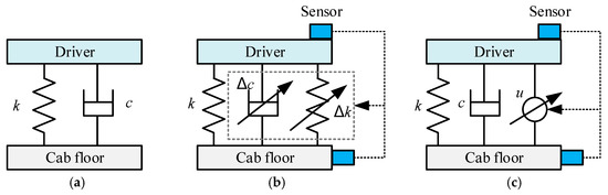
Figure 2.
Physical simplified model of 1-DOF seat suspension system. (a) Passive suspension; (b) semi-active suspension; (c) active suspension.

Table 1.
Comparison of characteristics of three suspension systems.
The passive suspension system is the earliest system applied to agricultural machinery seats, with a simple structure usually composed of springs, dampers, etc., as shown in Figure 2a. The world’s first three-wheeled vehicle, invented and patented by German inventor Carl Benz in 1886, used a passive suspension system with leaf springs as the damping elements [36]. The passive suspension system is the most developed, widely used, and diverse type of suspension system, with advantages such as simple structure, stable performance, low cost, and ease of installation, maintenance, and servicing. However, the parameters of the passive suspension system are non-adjustable, and optimal vibration damping can only be achieved under specific road conditions. When the vehicle’s driving state or road conditions change and approach the natural frequency of the passive suspension, the vibration effect is amplified, leading to increased vehicle vibrations and deteriorated ride comfort and handling stability. To address the irreconcilable conflict between ride comfort and handling stability in passive suspensions, researchers have proposed various solutions. One approach involves designing and studying negative-stiffness suspension systems by adding springs and improving the suspension structure to give linear suspension systems nonlinear dynamic characteristics, thereby improving the vibration damping effect within a specific frequency range [37,38,39]. Another approach utilizes the inerter–spring–damper (ISD) suspension structure, where the energy storage effect of the inerter helps achieve vibration damping in the low-frequency range [40,41,42,43,44]. Although different forms of improvements have been made to passive suspension to achieve good damping effects within a certain frequency range, this form of suspension system does not have a feedback control loop, and the suspension parameters are constant, only capable of passive response.
The semi-active suspension system generally adjusts and controls the suspension system through damping elements with adjustable damping coefficients or/and elastic components with adjustable stiffness, as shown in Figure 2b. The performance of semi-active suspension lies between passive and active suspensions. It requires minimal energy input to modify the dynamics of the suspension system, achieving characteristics comparable to those of active suspension. Additionally, semi-active suspension systems feature fail-safe characteristics; in the event of a failure in energy supply, the system reverts to a passive suspension, continuing to function. Since semi-active suspensions can only passively adjust damping forces or/and spring forces based on the suspension’s vibration, and cannot actively generate control forces, their control performance is not as ideal as that of active systems. However, semi-active suspensions offer advantages over active suspensions, such as a simpler structure, lower energy consumption, reduced cost, and greater reliability, making them more applicable and garnering increasing attention from researchers.
The active suspension system generates driving forces through actuators that produce forces of arbitrary magnitude and direction based on control conditions. Figure 2c shows an active suspension system with actuators working independently. The actuators used in active suspensions are generally divided into three types: electromagnetic actuators, hydraulic actuators, and pneumatic actuators [17,45,46]. Electromagnetic actuators generate driving forces using linear or conventional rotary motors, hydraulic actuators use hydraulic servos to generate driving forces, and pneumatic actuators use air springs to generate driving forces. The choice of actuator type plays a crucial role in implementing vehicle vibration control and influencing both vehicle performance and comfort. Active suspension systems balance vehicle smoothness and handling stability, making them the most effective method for enhancing ride comfort and handling stability. However, active suspensions require high-precision sensors, and their complexity, high energy consumption, expensive costs, and low reliability significantly limit their widespread adoption.
2.2. Evaluation Indicators for Ride Comfort of Seat Suspension System
The frequency, intensity, and duration of vibrations are closely related to physiological effects on the human body. Prolonged exposure to low-frequency vibrations can not only cause fatigue but also increase the possibility of resonance or harmonic oscillation between the body and the external environment, thereby impacting the operator’s physical and mental health [47,48,49,50]. Therefore, quantifying the ride comfort of the suspension system and its constraints is fundamental to the study of vibration characteristics in agricultural machinery seat suspension systems.
2.2.1. Ride Comfort Analysis
Ride comfort is positively correlated with the vibration acceleration experienced by agricultural machinery operators. The magnitude of acceleration directly influences the comfort effect. The human body, as a multi-degree-of-freedom vibrating system, is affected by the amplitude, frequency, and direction of vibration acceleration [51,52,53]. Furthermore, an individual’s sensitivity to vibration varies depending on their physical and mental state. The ISO standard 2631-1:1997 (R2018) provides methods for measuring, evaluating, and calculating the impact of vehicle-induced vibrations on human comfort [54]. The riding comfort of agricultural machinery seats can be quantitatively analyzed using acceleration power spectral density (PSD), Meister chart, comfort level, and seat effective amplitude transmissibility (SEAT) values.
- Acceleration Power Spectral Density
Acceleration power spectral density is the relationship between the power content and frequency of acceleration signals [47]. It is commonly used to describe random bandwidth signals. Acceleration power spectral density can be used as a smoothness evaluation index to determine the acceleration frequency components of the spring-loaded mass of the seat suspension. The PSD function for acceleration G(f) is expressed as
where a(k) is the discrete Fourier transform value of the acceleration signal; an is discrete acceleration; G(f) is acceleration PSD; and k = 0, 1, 2, …, Nd−1, Nd is the number of measurement points.
- 2.
- Meister Chart
The Meister chart is used to represent the relationship between the acceleration RMS and the frequency domain in the vertical vibration direction. The vertical vibration sensitivity range of the human body is 4 Hz~8 Hz. Therefore, the designed semi-active seat suspension structure and its control methods should effectively control the vertical vibration acceleration within this range [55]. The ISO standard 2631-1:1997 (R2018) uses a weighting curve to adjust the acceleration RMS of the Meister chart. The specific expression for the weighting function is as follows:
where is the root mean square value of the weighted acceleration, flower is the lower limit of the 1/3-octave bandwidth, fupper is the upper limit of the 1/3-octave bandwidth, W(f) is the weighting curve, and i = 1, 2, 3, …, 20.
- 3.
- Comfort Level
The comfort level is evaluated using weighted acceleration. For evaluating seat system vibrations, common measures include time-domain vibration acceleration, acceleration RMS, frequency-domain-weighted acceleration RMS, and three-axis weighted acceleration RMS. The standard ISO 2631-1:1997 (R2018) recommends using the total weighted acceleration RMS value as a comfort evaluation index for vibration [55,56]. In order to quantitatively evaluate the driver’s vibration response to the seat system, the comfort index in standard ISO 2631-1:1997 (R2018) is used to explain the specific evaluation method of the seat system under different vibration intensities.
The peak coefficient (P) can be used to study whether the basic evaluation method is suitable for describing the intensity of the impact of vibration on the human body. The peak coefficient is defined as the modulus of the ratio between the time history of weighted acceleration aw(t) and its RMS value aw, and its mathematical expression is as follows:
There are two vibration evaluation methods according to whether the peak coefficient is greater than 9: when the peak factor is less than or equal to 9, the basic evaluation method is used, and otherwise, the auxiliary evaluation method is used.
- (1)
- Basic Evaluation Method
Seat comfort is evaluated by the weighted acceleration of the chair surface in X (longitudinal), Y (transverse), and Z (vertical) directions. The calculation formula of weighted acceleration RMS is as follows:
where awx, awy, and awz correspond to the root mean square of the weighted acceleration on the X axis, Y axis, and Z axis of the orthogonal coordinate axis, respectively; kx, ky, and kz are the direction factors.
To facilitate controller design and improve computational speed, a time-domain filter is used to weight and filter the collected vibration acceleration time-domain signals, obtaining the weighted acceleration root mean square value. Then, through Equation (4), the total vibration amount is obtained. Alternatively, after weighting the frequency-domain data using a 1/3-octave bandwidth conversion, the total frequency-weighted acceleration root mean square value can be obtained. The vibration comfort is evaluated based on Figure 3, which is derived from the ISO 2631-1:1997 standard. This figure illustrates the statistical adaptation levels of human subjective responses to different ranges of vibration acceleration.
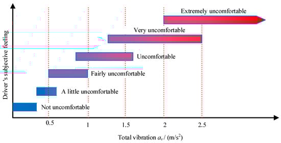
Figure 3.
Subjective assessment of comfort depending on total vibration value.
- (2)
- Auxiliary Evaluation Method
The fourth-power vibration dose value (VDV) method, as an auxiliary evaluation method with the peak coefficient P > 9, is more sensitive to the peak value of vibration acceleration than the basic evaluation method. The expression of the fourth-power VDV of the vertical motion of the seat suspension system is as follows:
- 4.
- Seat Effective Amplitude Transmissibility (SEAT) Values
The performance of seats in isolating the vibration from the floor can be predicted by SEAT values. SEAT values are calculated by the ratio of the weighted acceleration root mean square (RMS) measured on the vibrating seat to the weighted acceleration RMS measured on the floor [57,58,59].
where the RMS vibration magnitudes were determined for the vertical vibration measured on the seat base, surface of the seat, and thigh. The mathematical expression for RMS is as follows:
where a(t) is the frequency-weighted acceleration in the time domain (in m/s2), and T is the measurement period (in seconds).
SEAT values below 100% imply that the seat is isolating the vibration on the floor and thus reducing the discomfort from vehicle vibration.
2.2.2. Suspension System Constraint Analysis
The agricultural machinery seat suspension system is subject to constraints such as the layout of the cabin space, the shear-type seat structure, the maximum stroke of the cylindrical damper, the driver’s seating posture, and ease of operation. Its dynamic travel is limited, and when the system exceeds the allowable dynamic deflection, a suspension bottoming-out phenomenon (collision with the limit block) occurs, affecting the service life of the seat suspension system and exacerbating driver discomfort [60]. Reducing the dynamic deflection of the seat suspension is an inevitable requirement for seat structure design and control. However, if the suspension dynamic deflection is too small, the spring will have difficulty functioning, making the seat suspension system stiff and reducing its ability to effectively absorb vibrations. Therefore, by combining semi-active control methods, a reasonable design of the dynamic deflection of the seat suspension system can not only reduce the probability of bottoming out and extend the lifespan of the spring, but also improve ride comfort. The root mean square value of the suspension dynamic deflection of the semi-active seat suspension system is often used to analyze its vibration characteristics, and its expression is as follows:
where zs is the vibration displacement of the seat’s sprung mass, and zc2 is the vibration displacement of the seat base.
2.3. Seat Semi-Active Suspension System
The structural design principles of four typical agricultural machinery seat suspension systems are shown in Figure 4. The seat in Figure 4a is capable of moving both vertically and horizontally, occupying a large amount of space in the cabin layout, and is used for simple structures in tractors with large layout spaces. Figure 4b,c show suspended seats with compact structures. Figure 4d represents a shear-type seat, which is more commonly used in agricultural machinery and construction machinery. By improving the four passive seat suspension systems in Figure 4, one can obtain semi-active suspension systems with variable stiffness and/or damping.
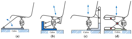
Figure 4.
Schematic diagram of tractor seat suspension structures. (a) Rocker seat; (b) front suspension seat; (c) rear suspension seat; (d) scissor seat.
2.3.1. Variable-Stiffness Semi-Active Suspension System
A variable-stiffness semi-active suspension is primarily implemented using an oil–gas spring and air spring, with the structural principle shown in Figure 5. An oil–gas spring utilizes a sealed chamber filled with gas (typically nitrogen) and hydraulic oil to provide adjustable stiffness and damping characteristics. Figure 5 illustrates the structure and working principle of the air suspension system for the seat. Through adjustments to the position of the control valve, the inflation pressure of the air chamber is varied, enabling the system to achieve different variable stiffness characteristics. Air suspension systems are widely researched and applied in cargo vehicles, buses, construction vehicles, and agricultural machinery [9,24,61]. They feature a simple structure, ease of implementation, and low cost. The spring stiffness coefficient can be changed by adjusting the air pressure inside the rubber airbags. The stiffness of air suspension can be adjusted according to the vehicle’s load, speed, and operational state to achieve a good suspension natural frequency, improving vehicle ride comfort. It can also be used to adjust the height of the vehicle body or seat to accommodate different body weights or human body masses.
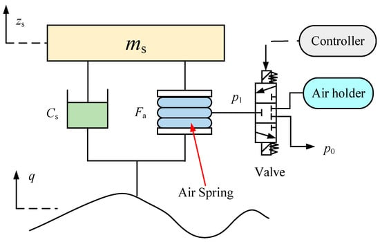
Figure 5.
Structure diagram of air spring seat suspension system [62].
Zheng et al. [63] applied the air spring suspension system to tractor seats and established a nonlinear half-vehicle dynamic model. By adjusting the air valve, they studied the impact characteristics of the RMS value of the vertical acceleration on the seat. Zheng et al. [64,65] focused on studying the effects of the oil–gas suspension system on the vibration characteristics of tractors, applying oil–gas springs to the front axle of the tractor. Through simulations and experiments, they verified that the front axle could improve tractor handling stability, but it reduced ride comfort for the driver. Based on the characteristics of hydro-pneumatic suspension systems, Sun et al. [66] adopted the fuzzy sliding mode control method of the fast power reaching law for control, which effectively improves the ride comfort and driving comfort of engineering vehicles. Zhu et al. [67] studied the vibration characteristics of the air suspension shear seat with an additional air chamber, focusing on the nonlinear relationship between the inherent frequency of the seat suspension and the throttle valve opening size. Cheng et al. [68] designed a bellows-type air spring and, through the analysis of the rubber airbag’s mechanical characteristics, established a variable stiffness model. Visteon designed a driver seat with a damper and air spring and researched the comfort of the driver. John Deere applied an air spring seat to 9020 series tractors. This air spring includes a hydraulic actuator, which is connected in parallel with the air spring. The load on the seat is shared by both components. During tractor operation, the vibrations generated can be alleviated by the hydraulic actuator. The hydraulic actuator’s role is to produce the optimal damping force to reduce the acceleration transmitted to the human body. Additionally, this air spring includes an auxiliary air chamber, which can change the stiffness of the seat suspension by controlling the throttle valve opening to achieve the optimal vibration damping effect.
The variable-stiffness semi-active suspension system has the advantages of low stiffness, light weight, low noise, and adjustable height. However, controlling the stiffness of the elastic components is challenging, and issues such as air leakage due to poor sealing and wear, as well as poor precision and real-time performance, are common.
2.3.2. Variable-Damping Semi-Active Suspension System
The variable-damping semi-active suspension system uses a damper with adjustable damping as the actuator. According to the control method, the energy of the suspension system is dissipated to achieve the effect of vibration reduction. To achieve semi-active damping control, the following three energy dissipation devices are commonly used to achieve the required damping: servo/solenoid valve damper, magnetorheological/electrorheological damper, and electromagnetic damper [69].
- Servo/Solenoid Valve Damper
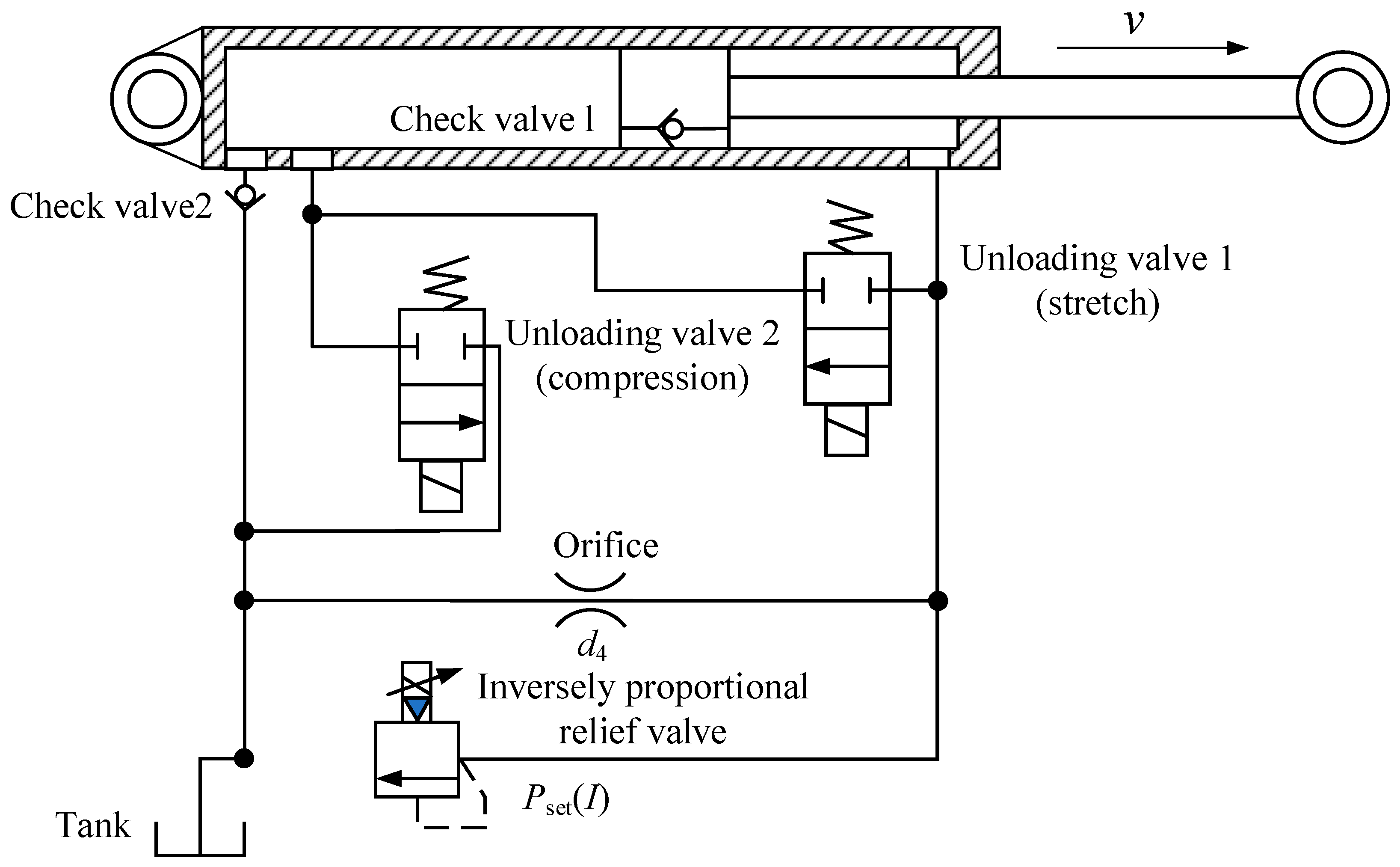
The servo/solenoid valve damper is realized by adjusting the cross-sectional area of the valve hole of the hydraulic shock absorber through the servo valve or the solenoid valve. Figure 6 is a structural sketch of the servo/solenoid valve damper, also known as the semi-active hydraulic damper, which is regulated by an oscillating proportional relief valve [70,71]. A valve actuator applied to a semi-active damper needs to have the following characteristics:
(1) The valve opening must satisfy the stroke requirements when the damper is at maximum speed;
(2) The maximum pressure that the valve body can withstand must account for the pressures at both ends of the damper;
(3) The response speed of the controllable valve must be fast enough to meet the requirements of the damping characteristics of the semi-active suspension [72].
Graczykowski and Faraj [73] studied the dynamic characteristics of a servo valve damper subjected to shock excitation using predictive control. This damper consists of an adjustment valve and a hydraulic actuator. Weber et al. [74] proposed a semi-active cable damper with negative stiffness, emulating skyhook damping. This is achieved through a hydraulic damper with a real-time-controlled by-pass valve, which compensates for reduced motion and efficiency due to the cable’s bending stiffness and fixed support conditions. The solenoid valve damper uses electromagnetic principles to control the switching frequency of the valve body, thereby adjusting the damping coefficient of the damper. The solenoid valve does not have the ability of fast response and accuracy of the servo valve, but the solenoid valve is simple in design, is low in cost and easy to process, and can optimize the stroke, damping force, and packaging of the damper.
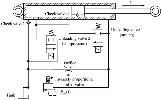
Figure 6.
Servo/solenoid valve damper structure diagram [75].
Figure 6.
Servo/solenoid valve damper structure diagram [75].
- 2.
- Electrorheological (ER)/Magnetorheological (MR) Dampers
The successful development of new smart materials such as electrorheological fluid (ERF) and magnetorheological fluid (MRF) and their application in dampers have led to rapid advancements in the research and design of semi-active damping suspension systems. Electrorheological or magnetorheological dampers are a type of hydraulic damper (see Figure 7), consisting of a hydraulic cylinder filled with ERF or MRF (usually oil). These rheological fluids contain tiny polarizable particles. ERF and MRF are non-Newtonian fluids that change their properties when exposed to electric or magnetic fields. Micron-sized iron particles suspended in the carrier liquid (such as water, petroleum-based oil, or silicone oil) align in chain-like structures along the flux lines of the electric or magnetic field, thereby altering the rheological characteristics of the fluid. When exposed to an electric or magnetic field, ERF/MRF materials can change from a free-flowing viscous fluid to a semi-solid state within milliseconds. The mechanical performance of ERF/MRF dampers is highly reliable because they contain no moving parts.
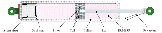
Figure 7.
Structure diagram of a single-cylinder single-rod MR damper [76].
The performance of ERF and MRF differs, as shown in Table 2 [77,78,79]. ERF operates at a high voltage and is sensitive to impurities and temperature. It has a small yield stress, and its response speed is temperature-dependent, exhibiting fast responses only within a specific temperature range. These characteristics limit the engineering applications of ERF [80]. To improve the dynamic properties of ERF and MRF, Chaichaowarat [81] and Padma [82] applied nanoparticles to the field, enhancing the overall performance of the damper. Li et al. [83] used nanoscale magnetic particles (Co-γ-Fe2O3 and CrO2) as additives to improve the sedimentation stability of magnetorheological fluid. Han et al. [84] synthesized a core/shell Fe3O4 composite nanoparticle material, which has soft magnetic properties, stronger density adaptability, and higher stability, improving the sedimentation stability of MRF.
Table 2.
Feature comparison of ERF and MRF.
The microstructure diagram and working principle diagram of MRF under no magnetic field and a magnetic field are shown in Figure 8. It can be seen from Figure 8a,c that the particles of MRF are in a chaotic state under zero magnetic field or no magnetic field. From Figure 8b,d, it can be seen that when a magnetic field is applied between the electrodes, the magnetic particles align in chains or bundles along the direction of the magnetic field. With an increase in the magnetic field, the number, length, diameter, and viscosity of the chain or bundle structure increase, and the damping coefficient increases. On the contrary, the damping coefficient decreases.
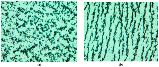
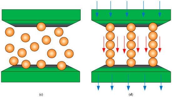
Figure 8.
Micro-structure and working principle of MRF [85]. (a) Micro-structure without magnetic field; (b) micro-structure with external magnetic field; (c) working principle without magnetic field; (d) working principle with external magnetic field.
The working voltage of the MR damper is low, which is consistent with the matching voltage of the vehicle, and no voltage transformation is required; the response time is about 10 ms; the shear yield strength is 25–50 times higher than that of electrorheological fluid; it has a wide adjustable range, with stable and reliable operation; and the equipment is simple to prepare and small in size. Therefore, the MR damper has become a hotspot of research and applications [86,87,88]. Jiang et al. [89,90,91,92,93] conducted in-depth research on the dynamic characteristics of a self-made MR damper, proposed different dynamic models of the MR damper based on the test data, and verified the accuracy and effectiveness of the model. Then, they applied a designed MR damper to a six-DOF vibration platform and performed simulation analysis and experimental verification using an on–off semi-active control strategy [94]. The results confirmed that the MR damper-based six-DOF vibration platform could effectively reduce the vibration transmitted to the isolation system. Meng et al. [95] applied an MR damper to a seat vibration damping system and performed a simulation analysis of the vibration characteristics of the semi-active seat suspension system. Zhu et al. [18,96] studied the dynamic characteristics of the MR damper, established mathematical models, and applied them to a scissor seat suspension system. By using it in parallel with air springs, they experimentally verified the effectiveness of semi-active control. Nguyen et al. [97,98,99] tested and analyzed the dynamic characteristics of a self-made intelligent damper–MR damper, and proposed different semi-active control methods. The effectiveness of semi-active control and the stability of the MR damper were verified by a bench test, which laid a theoretical foundation for the popularization and application of the MR damper.
- 3.
- Electromagnetic Damper
An electromagnetic damper utilizes the interaction between a permanent magnet or electromagnet and a moving coil within a magnetic field to achieve variable damping characteristics. Electromagnetic dampers have a fail-safe protection feature, meaning that when the coil is short-circuited or connected to an external resistor, they act as linear mechanical dampers [100,101,102,103]. The principle of the electromagnetic semi-active seat suspension differs significantly from that of magnetorheological and electrorheological fluid dampers. It converts seat vibration energy into electrical energy and alters the damping value of the electromagnetic damper by adjusting the resistance in the control circuit. Due to the ability to rapidly change the effective resistance through electronic control, the electric actuator can serve as a semi-active damper in vehicle or isolation suspension systems. Qin et al. [100] designed a self-sensing semi-active electromagnetic damper, utilizing the variable damping principle of a permanent magnet synchronous motor (PMSM) to autonomously acquire suspension status information without the need for external sensors, as shown in Figure 9. Ning et al. [104,105,106] used a three-phase generator and reducer to form an electromagnetic damper, which was installed in the seat suspension system. They designed and validated a semi-active controller for vibration control. Amjadian et al. [107] studied a magneto-solid damper (MSD), which includes a ferromagnetic plate, two copper plates placed parallel to either side of the ferromagnetic plate, and a permanent magnet array positioned between the ferromagnetic plate and the two copper plates. The motion of the permanent magnets generates eddy current damping forces, with the eddy current damping force having a linear relationship with the motion speed at low frequencies. Through changes to the arrangement of the permanent magnets, the eddy current damping coefficient can be increased, further enhancing the dissipation ability of both the eddy current damping part and the damper itself. Sun et al. [108,109] proposed a hybrid tunable damper, consisting mainly of magnets, coils, and a shunt circuit. The relative movement between the magnet and coil generates an electromotive force, and the damping coefficient is varied by altering the external resistance.
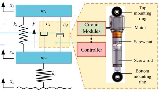
Figure 9.
Structure of electromagnetic damper suspension system [100].
Electromagnetic dampers have the advantages of a compact structure, light weight, simple control, and easy disassembly, which have garnered increasing attention from damper suppliers and automotive companies. They are commonly used in new and upcoming products and concept vehicles. However, the high cost of electromagnetic dampers remains a significant barrier to their widespread application.
2.4. Active Seat Suspension System
The main difference between the active suspension system and the semi-active suspension system is that the former can carry out real-time feedback and the dynamic adjustment of external environment changes to achieve the best comfort effect [110,111,112]. The active suspension system includes sensors, actuators, and control algorithms. Its core lies in the real-time collection of vibration data from the operational environment, which are used by the controller to actively adjust the dynamic characteristics of the suspension, optimizing comfort and stability.
In recent years, active seat suspensions have become a research hotspot due to their significant advantages in improving driver comfort [10,113,114,115]. Various active actuator solutions have been proposed, including hydraulic systems, pneumatic systems, and electric motors. Gan et al. [116] designed an active seat suspension based on dual linear electric cylinders to reduce the vibration levels transferred to the seat base and occupant’s body under low-frequency periodic excitation. Maciejewski et al. [117] developed an active suspension system combining hydraulic dampers and controllable air springs, which demonstrated excellent system robustness within the frequency range of 0.5 to 4 Hz and comparable damping performance to passive suspensions under high-frequency vibrations. The system designed by Kawana and Shimogo [118] utilizes a servo motor and ball screw drive, obtaining the vibration status through integrated seat contact surface, seat frame, and cockpit floor acceleration signals for precise control. For low-frequency vibrations, Le et al. [119] proposed a pneumatic damping system based on a negative-stiffness structure and addressed the system’s time-varying and nonlinear characteristics with an adaptive intelligent feedback controller. Périsse and Jezeque [120,121] designed an active seat suspension using a rotating motor and a gear–rack mechanism to convert rotational torque into vertical force to achieve vibration reduction. Ning et al. [122,123,124] directly integrated a rotating motor into a traditional scissor-type seat suspension system to enhance the vibration reduction performance, as shown in Figure 10.

Figure 10.
Motor-driven seat suspension system. (a) Structure diagram of seat suspension system; (b) the actual installation position and structure prototype.
3. Research Status of Seat Semi-Active Suspension System Control Technology
The structural principle of the semi-active seat suspension control system is shown in Figure 11, including the sensor measurement system, seat suspension system controller, semi-active control system, power supply system, etc. The road excitation signal is transmitted to the human body through the suspension. The sensor measures the vibration response parameters of the seat suspension system in real time, and then the system controller calculates the required damping force. The variable stiffness or variable damping signal is obtained by the semi-active control system, and the seat semi-active suspension system is subjected to feedforward or feedback control to obtain ideal ride comfort.
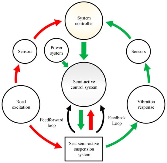
Figure 11.
Schematic diagram of semi-active seat suspension control.
The system controller is crucial in influencing the performance of the semi-active suspension system, and designing the controller is essentially designing the control algorithm, which plays a key role in the effectiveness of control. The control effects obtained using different control methods are not the same. So far, control methods have developed from classical control to modern control. With the rapid rise in computer technology, intelligent control has developed rapidly. At the same time, single control methods have been unable to meet the requirements for obtaining a better control effect. More and more composite control methods have attracted attention, and a composite control method combining multiple control methods has been proposed to solve some of the defects of a single control method.
3.1. Single Control Method
Single control methods are simple and convenient, capable of directly controlling the design objectives. Research on single control methods is extensive, and in the early stages, single control methods were commonly used to design vehicle suspension systems to meet the requirements of vehicle ride comfort and handling stability. In 1974, Karnopp proposed the canopy control method and applied it to semi-active suspension systems [125]. In 1922, Minorsky introduced the PID control method, which is widely used in industrial fields today [126]. This led to the development of nonlinear control methods such as sliding mode control [127], model predictive control [128], robust control [129,130], fractional-order proportional–integral–derivative (FOPID) control [131], reinforcement learning control [132,133], and other modern control methods, as well as intelligent control methods such as neural network control [134], fuzzy control [135], and machine learning control [136].
3.1.1. Skyhook Control
The principle of skyhook control is to design an adjustable damper to connect the suspension and the sky (inertial reference point) to reduce the vertical transmission of vibration energy and improve ride comfort [137]. Skyhook control mainly reduces the acceleration and dynamic deflection of the sprung mass, so as to obtain the best vibration reduction effect. Skyhook damping control is an ideal semi-active control method, but it cannot be realized in practical control. It is often used as a reference model to track the best motion state. The skyhook control design is simple and easy to simulate, and its damping switching is fast. It is often used as a benchmark control method to compare the advantages and disadvantages of other control methods.
Mauricio et al. [138] used the skyhook control method to study the wheel-side semi-active suspension of electric vehicles and compared it with different control methods. Papaioannou et al. [139] used the skyhook control method to control the quarter-vehicle model and simulated it through different road excitations. Liu et al. [140] proposed a new general theory of skyhook control and applied it to the design of a semi-active suspension control strategy, which improved the performance of the vehicle suspension system. Zhu et al. [141] applied the skyhook control strategy to the cab seat suspension system with an MR damper. The semi-active seat suspension structure and the skyhook control principle diagram are shown in Figure 12. The simulation and experimental analysis were carried out under the condition of random road excitation and sinusoidal excitation. It was verified that skyhook control can significantly reduce the acceleration RMS value of the semi-active seat suspension system and provide ride comfort. Munyaneza et al. [142] used the skyhook controller to control the hybrid MR damper of a semi-active seat suspension based on the human biodynamic model. A controllable semi-active hybrid magnetorheological seat suspension and the conventional magnetorheological seat suspension were compared with the uncontrolled road excitation system. The simulation results show that driver seat comfort with skyhook control is significantly improved compared to without skyhook control.

Figure 12.
Seat semi-active suspension structure diagram and skyhook control schematic diagram with MR damper [141]. (a) The structure of the scissor-linkage seat; (b) a schematic diagram of skyhook control for the seat suspension.
The connection point of the skyhook control method is a fictitious point that does not change with the movement of the suspension system, which cannot be found in reality. The use of skyhook control to control active actuators or semi-active actuators cannot achieve the theoretical vibration reduction effect. Researchers often use skyhook control as a reference to improve the design of other control methods, thus proposing a large number of optimal control methods.
3.1.2. PID Control
PID control, as a typical representative of classical control algorithms, is a traditional control technique suitable for deterministic systems with accurate mathematical models. PID control consists of three components: proportional, integral, and derivative, which involve comparing the actual output with the ideal value and adjusting the deviation until the set requirements are met [143,144,145]. Tuning the parameters is the core of PID control design. With advantages such as simple algorithms, strong robustness, ease of operation, and high reliability, PID control has been widely applied in engineering practice [146,147]. It is used in 90% of industrial control processes and achieved using PID controllers and their corresponding improved versions [148].
In suspension systems, PID control has been applied more extensively, as shown in Figure 13. Zhang et al. [149] used a PID controller to control the suspension system and tuned the three parameters of PID using orthogonal experimental methods. The feasibility of the PID control method was analyzed through numerical simulations. Song [150] built a simulation model of the system in MATLAB 2018a/Simulink, inputted different road signals, and obtained the parameters of a tractor’s semi-active seat suspension system with and without PID control. The experimental results showed that PID-controlled active seat suspension can improve the driver’s comfort.
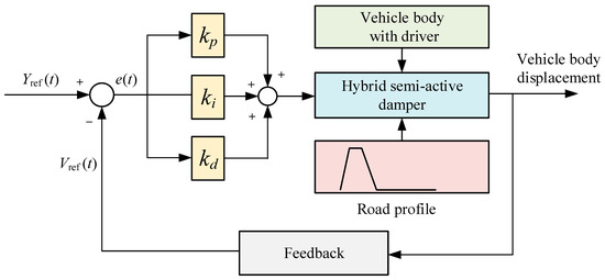
Figure 13.
PID control schematic diagram [151].
Due to the time delay, nonlinearity, and parameter uncertainty of practical engineering control, obtaining ideal results with PID control based on an accurate model is difficult [152], and it often needs to be combined with other control or intelligent optimization algorithms to achieve the best results.
3.1.3. Sliding Mode Control
Sliding mode control (SMC) is a kind of variable structure control. Through the switching of the control variables, the system state moves along the state trajectory of the predetermined sliding mode, so that the system is invariant when subjected to parameter perturbation and external interference. This characteristic makes sliding mode control valued by scholars in various countries [153]. Sliding mode control is suitable for deterministic systems and uncertain systems, linear systems, and nonlinear systems. It has the characteristics of a simple method, easy implementation, and high robustness to model parameter uncertainties and external disturbances.
The control principle of SMC in an MR damper seat semi-active suspension system is shown in Figure 14. Lv et al. [154] used SMC to control a five-DOF semi-active seat suspension system with a human body model, simulated and analyzed it on a C-level road surface, and compared it with PID control. The results show that the vibration acceleration of the seat suspension is significantly reduced. Soosairaj et al. [155] used SMC to simulate a three-DOF seat suspension, and compared first-order SMC and second-order SMC in the time domain. As an alternative to traditional SMC, a moving sliding mode surface is proposed by introducing a spiral function and a switching function. This method can improve the robustness of the sliding mode surface and reduce the time taken to reach the sliding mode surface [156]. Fan et al. [157] used SMC to control semi-active three-RPS seat suspensions. The simulation results show that the sliding mode control method can effectively suppress the vibration of the vehicle and improve ride comfort.
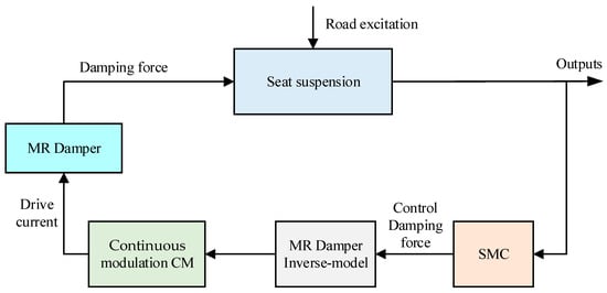
Figure 14.
SMC schematic diagram [158].
SMC has strong robustness for nonlinear and uncertain systems but achieves invariance to system parameter perturbations and external disturbances at the cost of high-frequency chattering in the control signal. High-frequency chattering can excite unmodeled dynamics in the system, negatively affecting the system’s performance. Therefore, eliminating or mitigating chattering has become a key focus of research in sliding mode control.
3.1.4. Fuzzy Control
Fuzzy mathematics and fuzzy control were first proposed by L. A. Zadeh. In 1974, Professor E. H. Mamdani first applied fuzzy control to the operation control of boilers and steam turbines [159]. Fuzzy control, which falls under intelligent control, mimics human thinking and judgment patterns in system control to achieve the desired effect. It fundamentally addresses the challenges faced by classical and modern control theories when applied to uncertain and complex systems.
The concept of fuzzy sets (FSs) was first proposed by L. Zadeh in 1965 to represent uncertain system parameters. However, in many real-world systems, uncertainty arises from multiple sources, such as inconsistent opinions from different experts, difficulty in finding appropriate membership functions, and diversified noise sources. In such cases, Type-1 (T1) fuzzy sets or traditional FSs have limited ability to model uncertainty. Due to these factors, Zadeh introduced the concept of higher-order FSs in 1975. However, for more than a decade, these FSs received little attention from the scientific community. Starting in 1997, many researchers began exploring Type-2 (T2) fuzzy sets, specifically interval Type-2 fuzzy sets (IT2FSs), and developed a solid theoretical foundation, which attracted increasing academic interest. The interval Type-2 fuzzy logic system (IT2FLS) consistently outperforms or at least matches the performance of the Type-1 fuzzy logic system (IT1FLS) [160,161,162,163]. Interval Type-2 fuzzy logic control (IT2FLC) can directly handle the uncertainty and disturbances associated with nonlinear problems, gaining increasing attention from researchers.
The application principles of T1 fuzzy control and interval T2 fuzzy control strategies in seat suspension systems are shown in Figure 15. Tang et al. [164] studied a Takagi–Sugeno T1 fuzzy controller based on a state observer and applied it to a seat suspension system with a current-variable damper as the actuator. Through simulation and experimental verification, and comparison with the skyhook control method, the proposed fuzzy control method was shown to improve the performance of the semi-active seat suspension system. Wu et al. [165] introduced the T1 fuzzy control algorithm into the control system of a semi-active suspension, establishing mathematical and simulation models of a four-degree-of-freedom-vehicle semi-active suspension and designing the semi-active suspension fuzzy controller using MATLAB’s fuzzy logic toolbox. Kou et al. [166] applied the T1 fuzzy control method to a new type of electromagnetic hybrid suspension system. Through the simulation analysis and bench testing of the suspension’s dynamic performance and energy-harvesting characteristics, the effectiveness of the proposed T1 fuzzy control was verified. Aliasghary et al. [167] applied a single-input interval T2 fractional-order fuzzy (SIT2FOF) controller to the control of power system automatic voltage regulators and the active suspension system of a Kubota M110X tractor. In comparison with T1 fuzzy control, the results showed that the single-input interval T2 fuzzy (SIT2F) set reduced the computational workload and the number of parameter adjustments, while the SIT2FOF control technique more effectively dealt with external disturbances and model uncertainties. Xie et al. [168] studied the control effects of T2FLC on an uncertain nonlinear suspension system with actuator saturation and time delay characteristics. Through the use of a quarter-vehicle suspension model as the control target, numerical simulations and experimental tests validated the stability of T2FLC.
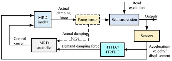
Figure 15.
Fuzzy control principle diagram of semi-active seat suspension.
The robustness of fuzzy control is better, but it depends on human experience and knowledge, and the selection of a membership function and the number of fuzzy control rules have a strong impact on the system.
3.2. Composite Control Method
Single control methods, such as the classical control method, modern control theory, and intelligent control method, fail to obtain the optimal control effect in simulations and practical application due to their own adaptive range and theoretical characteristics, which exposes some shortcomings of the original control theory [169]. Therefore, the combination of two or more control principles in classical control methods, modern control methods, and intelligent control methods to form a new composite control method has become a hotspot in the pursuit of better control effects [170,171,172,173,174].
In the control of semi-active seat suspensions, to achieve better vibration reduction, traditional control methods such as PID control are combined with intelligent control methods like fuzzy control to form fuzzy–PID control [88,175,176]. Additionally, intelligent optimization algorithms are applied to traditional adaptive control and combined with other control methods to form a new adaptive composite control method. Furthermore, fuzzy control is combined with SMC to create a fuzzy sliding mode composite control method [177]. The composite control method has a variety of combinations, and the control effect varies. It needs to be selected and compared with other methods according to the specific system characteristics.
3.2.1. Fuzzy–PID Control
Due to the widespread industrial application of PID control and the simplicity of its parameter adjustment methods, along with the strong nonlinearity and real-time characteristics of fuzzy control, the combination of fuzzy control and PID control is often applied in semi-active control systems. The fuzzy–PID control principle is illustrated in Figure 16 [88].
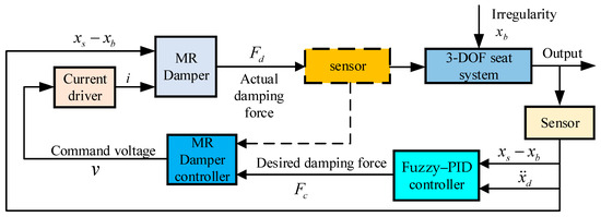
Figure 16.
Fuzzy–PID control principle diagram.
Hu et al. [178] used the fuzzy–PID control method to perform a simulation analysis on a semi-active suspension system integrated with an MR damper for a quarter-vehicle model. Through comparisons with various control methods, the study verified that the fuzzy–PID composite control method provided better performance for the vehicle suspension system under random road excitation. Jain et al. [179] studied the vibration mechanism of a fuzzy–PID control method in an eight-DOF quarter-vehicle–seat–human model. The seat suspension system utilized a two-DOF MR damper suspension structure. The researchers analyzed the acceleration vibration response of the human head in a semi-active seat suspension system under shock excitation and random road excitation, comparing it to a passive seat suspension system. Chen et al. [88] used fuzzy–PID control to study the vibration characteristics of a seat suspension system equipped with an MR damper. They created a quarter-vehicle model to analyze the seat acceleration and suspension dynamic travel under D-class road and shock road excitation conditions. The simulation results showed that fuzzy–PID control significantly improved ride comfort and handling safety compared to single PID control. Mohammadikia et al. [180] compared and analyzed the effects of T1 fuzzy–PID, T1 fractional-order fuzzy–PID, T2 fuzzy–PID, and T2 fractional-order fuzzy–PID control methods on the vibration characteristics of a tractor cabin suspension. The results indicated that the T2 fractional-order fuzzy–PID control method demonstrated stronger resistance to road disturbances compared to other control methods.
3.2.2. Integrated Intelligent Algorithm Composite Control
With the continuous upgrading of computer hardware and software, the ability of digital computing has been developed by leaps and bounds. Intelligent optimization algorithms such as Differential Evolution (DE) [181], the genetic algorithm (GA) [182], particle swarm optimization (PSO) [183,184,185], the firefly algorithm (FA) [186], Grey Wolf Optimizer (GWO) [187,188], and the Whale Optimization Algorithm (WOA) [189] have been rapidly applied and become new methods to solve the problem of traditional system identification. These intelligent algorithms are applied more and more to semi-active suspension control, which has become a research hotspot to improve vehicle ride comfort and stability.
The control principle diagram of a semi-active suspension system combined with an intelligent optimization algorithm (PSO/FA/GWO) and a single control strategy (fuzzy control) is shown in Figure 17 [190,191,192]. Ab Talib et al. [191] studied an intelligent optimizer of the advanced firefly algorithm to calculate the performance of the PID controller of a semi-active suspension system, and compared it with the classical firefly PID control method, PSO-PID control, skyhook control, and a passive system. The simulation results show that the proposed advanced firefly PID control method can significantly improve ride comfort. Ab Talib et al. [192] used PSO, the FA, and the improved FA to optimize the input and output parameters of the fuzzy controller to adjust the vehicle suspension to any interference effects. The response of the fuzzy control method of three different intelligent algorithms to the sprung acceleration and sprung displacement of the suspension was compared and analyzed. It was further verified that the improved firefly fuzzy control has a significant effect on improving the vibration characteristics of the semi-active suspension system, and the proposed intelligent control method has a fast calculation time, fast convergence speed, and high efficiency. Yong et al. [193] proposed a composite control method based on reinforcement learning. The composite control method has the ability of autonomous learning, and can select the Soft Actor–Critic (SAC) or skyhook control model according to the pulse detector and the vehicle speed. The switched learning system can continuously identify different road disturbance profiles in real time, so that the SAC model can be learned and applied accordingly. The effectiveness of the proposed integrated intelligent algorithm composite control method is proved by vehicle simulation and a real vehicle test, which can improve the ride comfort and handling stability of the vehicle.
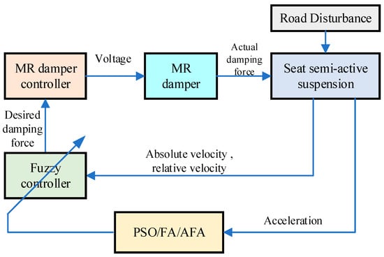
Figure 17.
Integrated intelligent algorithm composite control method principle diagram.
While the integrated intelligent algorithm composite control method can achieve optimal control parameters or self-learning to select the best switching mode, this control method requires high hardware specifications, a significant computational load, and high costs.
3.2.3. Fuzzy Sliding Mode Control
Fuzzy control can effectively and in real time handle imprecise system models and inaccurate sensor readings, while SMC is characterized by fast response, strong robustness, and high reliability. Combining these two control methods into a composite control approach can compensate for the shortcomings of each individual method, achieving fast response, strong anti-interference capability, and enhanced robustness [29,90,91,92,194,195]. The structure diagram of fuzzy sliding mode control is shown in Figure 18 [55].
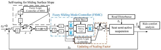
Figure 18.
Fuzzy sliding mode control principle diagram [55].
Han et al. [196] designed a composite controller, consisting of an IT2 fuzzy model, sliding mode variable structure controller, and adaptive controller, and applied it to the vibration control of a seat suspension with an MR damper. The robustness of the proposed composite control method was assessed using Lyapunov’s second law, and the vibration characteristics of the semi-active seat suspension under two different road conditions were analyzed through simulations. Lv et al. [154] improved the reaching law of the fuzzy sliding mode controller and simulated the vibration performance of a five-DOF semi-active seat suspension system with a human body model under C-grade road roughness and bumpy road conditions. Through comparison with PID control, the effectiveness of the proposed fuzzy sliding mode controller was verified. Shin et al. [197] studied the effect of adaptive fuzzy sliding mode control on the vibration characteristics of semi-active seat suspension systems. The robustness of the proposed composite control method was verified by a simulation and experiment, showing that it could significantly improve the ride comfort of the semi-active seat suspension system. Li [198] proposed a parallel adaptive IT2 fuzzy sliding mode controller, used for adjusting vehicle height and reducing acceleration, and built a test bench to validate the proposed composite control method. The results showed that the proposed control method could significantly reduce vehicle body vibration and improve ride comfort.
Research indicates that composite control methods are more suitable for complex systems like semi-active seat suspensions in vehicles, which are nonlinear, time-delayed, and uncertain, making them a trend in semi-active suspension control research. In particular, the ability of interval type-2 fuzzy control to directly handle inherent uncertainty, when combined with other control methods to form a composite adaptive fuzzy control method, makes the control system exhibit strong robustness in handling model uncertainties and external disturbances.
4. Key Technical Challenges of Agricultural Machinery Seat Semi-Active Suspension System
With the continuous improvement in agricultural mechanization, the comfort of operators has gradually become a critical issue that needs to be addressed during the design process. Semi-active suspension systems, due to their good balance between performance optimization and cost control, have gradually become an important choice in agricultural machinery seat suspension design. However, in practical applications, semi-active suspension systems still face numerous technical challenges, especially given the complexity and variability of agricultural machinery operating environments, which impose higher demands on system design and control. Therefore, in-depth research on and the resolution of these technical challenges are of great significance for further enhancing operator ride comfort. Based on this idea, this section will systematically analyze the main issues and technical bottlenecks that agricultural machinery seat semi-active suspension systems face in practical applications from multiple key technical perspectives.
4.1. Spatial Layout and Dynamic Performance Optimization Design of Seat Suspension
The spatial layout and dynamic performance optimization design of the seat suspension system are core issues in agricultural machinery suspension research. A reasonable spatial layout must overcome the structural limitations of the cabin space while enhancing the operator’s human–machine interaction experience. Dynamic performance optimization design, through accurate modeling and intelligent control technologies, ensures the vibration reduction performance of the suspension system under complex working conditions, thereby achieving both operator comfort and operational stability.
4.1.1. Flexible Design of Overall Layout
The spatial limitations within the agricultural machinery cabin, coupled with the diversity of functional equipment, present unique challenges for the layout of the seat suspension system [14]. The cabin typically includes multiple functional modules such as control panels, display devices, and pedal systems. The layout of the seat suspension system needs to coordinate with these components to ensure operational convenience and driving comfort. Additionally, agricultural machinery often needs to adapt to various operational requirements, which demands a high degree of flexibility in the layout design of the suspension system [199].
The design of the overall layout of the agricultural machinery seat suspension system must take the following factors into account:
- Coordination between spatial structure and ergonomics: optimize the structural design of the suspension system based on ergonomics, ensuring that the seat layout fits the driver’s height, visibility, and operating habits, reducing fatigue during long hours of operation.
- Matching of seat and human body’s center of mass: properly position the seat to ensure a dynamic balance between the human body’s center of mass and the seat suspension system, improving overall vehicle stability and reducing vibration transmission caused by imbalances.
- Pairing of elastic and damping components: scientifically configure the elastic and damping components of the suspension system to optimize suspension performance, thereby minimizing the transmission of mechanical vibrations and ensuring driver comfort in complex working environments.
Through the use of 3D modeling and optimization algorithms, the cabin space layout can be efficiently simulated and analyzed to ensure compatibility between the suspension system and the cabin’s internal functional modules. Fully considering flexibility and adaptability during the design phase not only enhances the driver’s comfort but also provides strong support for overall vehicle performance.
4.1.2. Dynamic Performance Optimization Design
The working environment of agricultural machinery is complex and variable, requiring the seat suspension system to possess excellent dynamic characteristics to maximize vibration isolation and improve operator comfort. The core of dynamic performance optimization design lies in the scientific adjustment of key suspension system parameters (such as stiffness, damping, and natural frequency) to maintain optimal performance under diverse working conditions [200,201,202].
A critical element of this design is the precise selection of passive spring stiffness, which must support the combined static weight of the seat and driver to ensure system stability. Additionally, the control force range of the semi-active damper (e.g., MR damper) must be carefully calibrated to ensure that the emulated negative stiffness can significantly influence the total system stiffness, comprising both passive and semi-active components [74]. This is crucial for controlling the natural frequency of the one-DOF system, which includes the seat and driver masses. By adjusting the passive spring stiffness and the force range of the semi-active damper, the system can effectively regulate the natural frequency and enhance vibration isolation, particularly within the low-frequency range (1–20 Hz), which is vital for optimizing operator comfort.
The main challenges faced in the optimization of design include the following:
- Nonlinear behavior of dynamic stiffness and damping
Agricultural machinery encounters significant nonlinear vibration characteristics during operation, such as ground impacts and long-term vibration accumulation, which requires the suspension system to have high adaptability to nonlinear vibrations.
- 2.
- Frequency adaptability and resonance avoidance
The frequency range of cabin vibrations is wide and complex, and the suspension system needs to avoid the low-frequency resonance zone (1–20 Hz) that is sensitive to the driver, while quickly dissipating high-frequency vibration energy to reduce vibration discomfort.
- 3.
- Working condition adaptability and real-time adjustment capability
The suspension system must be able to adjust its dynamic characteristics in real time according to changes in the working environment to ensure optimal vibration reduction in different working conditions.
To address these challenges, the following methods are used in dynamic performance optimization design:
- Nonlinear dynamic modeling
Use nonlinear dynamic models to study the dynamic response of the suspension system under complex vibration inputs, providing theoretical support for optimization design.
- 2.
- Multi-objective optimization
Use genetic algorithms or particle swarm optimization to perform multi-objective optimization of the suspension system’s stiffness, damping, and natural frequency, balancing vibration isolation effects and energy dissipation performance.
- 3.
- Adaptive control strategy
Combine MR dampers or electro-hydraulic dampers to design intelligent control systems that adjust the suspension system’s dynamic parameters based on real-time vibration signals, ensuring that dynamic performance remains at its optimal state.
- 4.
- Simulation and experimental verification
Use simulation tools (such as Adams 2024 and Simulink 2024) to model the dynamic behavior of the suspension system, and verify the optimization results through experimental testing to ensure consistency between the theoretical design and actual performance.
4.2. Complexity and Uncertainty of Working Environment
The working environment of agricultural machinery is complex and changeable, which poses a great challenge to the design and control of seat suspension systems. Dynamic and uncertain factors such as load fluctuations, climate change, working speed, and sudden obstacles require the suspension system to have strong adaptability and high robustness to ensure efficient vibration isolation performance [203].
- Load Fluctuations and Uneven Load Distribution
The variability and unevenness of mechanical load result from changes in the type of operation, such as plowing, seeding, and harvesting, where load differences can be significant. Harvesting heavy crops leads to rapid changes in vibration frequency and amplitude, while an uneven distribution of seeds and fertilizers can disrupt system balance. The suspension system needs to maintain stable vibration isolation performance through adaptive adjustment.
- 2.
- Climate and Environmental Conditions
Climate change significantly affects suspension system performance [204]. High temperatures may weaken the performance of damping components, low temperatures can affect the stability of elastic elements, and high humidity may increase friction or reduce component performance. These variations necessitate that the suspension system be designed to consider environmental adaptability to ensure reliable operation under diverse climatic conditions.
- 3.
- Working Speed and Timing
Changes in working speed will cause significant differences in vibration characteristics [205,206]. High-speed operation is prone to high-frequency vibration, while low-speed operation is accompanied by low-frequency and long-duration vibration. The suspension system needs to be able to dynamically adjust damping and stiffness characteristics to adapt to speed changes. In addition, changes in ground conditions in different seasons (such as soft soil in autumn and hard ground in spring) also require the suspension system to have good seasonal adaptability.
- 4.
- Working Obstacles and Sudden Events
External obstacles and unforeseen events demand rapid response from the suspension system [207]. For example, sudden obstacles like stones and tree roots can lead to instantaneous shocks, while extreme weather events such as storms or hail can quickly alter the operating environment. The suspension system must be capable of real-time perception and emergency adjustment to cope with these unpredictable disturbances.
4.3. Real-Time Performance and Robustness of Control Algorithms
The real-time performance and robustness of control algorithms are key factors that enable agricultural machinery seat suspension systems to effectively handle complex and uncertain operating environments [164,208,209]. Given the high level of uncertainty and dynamics in the agricultural environment, ensuring effective vibration isolation, especially enhancing the comfort of the operator, requires the suspension system to respond quickly and stably to changes in external conditions. Therefore, the control algorithms of the suspension system must be able to respond in real time and be robust to cope with various disturbances and uncertainties.
- Real-Time Issues in Control Algorithms
Agricultural machinery frequently encounters vibration shocks and irregular ground disturbances during field operations. The core task of the seat suspension system is to adjust the suspension parameters (such as damping and stiffness) rapidly based on these dynamic vibration signals, thereby minimizing the amplitude of vibration transmitted to the seat. This requires the control algorithm to have millisecond-level signal processing and response capabilities.
Real-time performance is primarily constrained by the control bandwidth of the semi-active actuator, such as the MR damper [147,152,210]. The key challenge lies in the current driver’s ability to regulate the coil current, which must compensate for the slow dynamic response of the coil current and the effects of eddy currents. While control algorithms like skyhook control, fuzzy control, and adaptive control involve real-time computations, the actuator’s response time ultimately determines the system’s real-time effectiveness.
- 2.
- Robustness Issues in Control Algorithms
Robustness refers to the ability of the system to maintain stability and good performance despite external disturbances, environmental changes, and internal uncertainties [211]. In agricultural machinery seat semi-active suspension systems, the high complexity and uncertainty of the working environment pose significant challenges to the robustness of control algorithms. Sudden changes in ground conditions, load fluctuations, and climate variations can affect the frequency, amplitude, and pattern of vibrations. Without sufficient robustness, control algorithms may fail to handle these disturbances, leading to a decrease in the suspension system’s performance, which could negatively impact the operator’s comfort and even compromise health.
4.4. Specific Issues and Improvement Measures
- External Disturbances and System Errors
The agricultural machinery working environment is filled with various uncertainties, including sudden ground changes (such as potholes or stones), component wear, sensor malfunctions, or errors. These errors can interfere with the control algorithm’s output and affect the suspension system’s accuracy. To cope with these disturbances, robust control algorithms need to possess strong adaptability and maintain vibration suppression effects in uncertain environments.
- 2.
- Environmental and Load Variations
During agricultural operations, factors such as uneven ground, load changes, and climate fluctuations can significantly impact vibration frequency and amplitude. If the control algorithm lacks sufficient robustness, it may fail to maintain good control performance in a dynamically changing environment. Therefore, the adoption of adaptive or fuzzy control algorithms is crucial. These algorithms can automatically adjust the control strategy based on real-time vibration signals, enhancing the system’s ability to respond to changes.
- 3.
- Uncertainties in Suspension Components
The performance of suspension components (such as dampers, springs, and shock absorbers) may change over time, especially due to aging, wear, and temperature fluctuations. Robust control algorithms compensate for these uncertainties, ensuring that the system maintains ideal vibration isolation effects under various operating conditions. Fuzzy control algorithms can adjust the suspension’s performance based on real-time feedback, allowing it to adapt to different operating conditions and component changes.
- 4.
- Nonlinearity and Complexity
The complexity of the agricultural operating environment means that the dynamic behavior of the suspension system often exhibits nonlinear characteristics. For example, the damping and stiffness of the suspension may vary nonlinearly with vibration amplitude and frequency. Traditional linear control algorithms struggle to handle these nonlinear characteristics accurately, leading to a decline in control precision. Robust control algorithms, such as sliding mode control and adaptive control, are more effective in dealing with nonlinearity and maintaining system stability and efficiency in complex environments.
5. Conclusions and Outlook
5.1. Conclusions
The agricultural machinery seat semi-active suspension system has gained significant attention in recent years as an important technology for improving operational comfort and reducing the impact of mechanical vibrations. A systematic analysis of existing research reveals that semi-active suspension systems have gradually become the focus of agricultural machinery suspension technology due to their excellent balance between performance and cost. From suspension system design to the development of vibration control technologies, various methods, such as fuzzy control, sliding mode control, adaptive control, and composite control strategies, are continuously optimized to address the challenges posed by changing vibration frequencies, external disturbances, and system uncertainties in complex agricultural operating environments. Additionally, the comfort evaluation indicator system based on the vibration transmission ratio, acceleration RMS, and suspension dynamic performance has been gradually refined, providing a reliable theoretical basis for related research and system optimization. However, current research still primarily focuses on single working conditions or laboratory environments, lacking comprehensive validation of system performance in real-world complex operating environments and under dynamic loads.
5.2. Outlook
Although significant progress has been made in improving comfort through agricultural machinery seat semi-active suspension systems, several challenges and unresolved issues remain. Future research can be directed toward the following four areas:
- In-Depth Application of Composite Control Methods
Composite control methods, which combine strategies like fuzzy control, sliding mode control, and predictive control, can achieve superior vibration suppression in complex operating environments. Future research will focus on optimizing and integrating composite control algorithms to enhance the system’s adaptability and control precision in dynamic environments.
- 2.
- Integration of Variable Stiffness and Damping Elements
Intelligent materials, such as magnetorheological fluids and shape memory alloys, offer the capability for active adaptation to vibration conditions through variable stiffness and damping components. Future development will focus on enhancing the performance of these components and their efficient integration with the suspension system to meet multi-frequency vibration control demands under various working conditions.
- 3.
- Synergistic Optimization of Composite Control and Intelligent Damping Elements
Combining composite control strategies with variable stiffness and damping components, and establishing real-time monitoring and dynamic adjustment mechanisms, will enable precise vibration suppression in complex vibration environments. Future research will concentrate on the synergistic optimization of both aspects to ensure efficient vibration damping and stable dynamic performance under complex operational conditions.
- 4.
- Development of Intelligent and Personalized Vibration Damping
Leveraging artificial intelligence technologies, adaptive optimization algorithms, and big data-driven intelligent sensing technologies will further enhance the automation and intelligence of seat suspension systems. Future development directions include personalized vibration damping strategies based on real-time data and intelligent learning and self-optimization capabilities during long-term use, providing higher levels of comfort and health protection for operators.
Author Contributions
X.C. and Z.W.: Methodology, literature collation, writing—original draft. H.S. and N.J.: Writing—review and editing. S.Z.: Chart drawing and visualization. Y.Q. and Q.L.: Supervision and conceptualization. All authors have read and agreed to the published version of the manuscript.
Funding
This research was funded by Henan Province Science and Technology Research Project (242102110360); Henan Provincial Key Research Projects for Colleges and Universities (25A460022, 25B460010, 25B460001); and Henan Institute of Technology High-level Talent Startup Funding Project (KQ2419).
Data Availability Statement
Data are contained within the article.
Conflicts of Interest
The authors declare no conflicts of interest.
References
- Coyte, J.L.; Stirling, D.; Du, H.; Ros, M. Seated whole-body vibration analysis, technologies, and modeling: A survey. IEEE Trans. Syst. Man Cybern. Syst. 2016, 46, 725–739. [Google Scholar] [CrossRef]
- Hilal, Y.Y.; Al-rajabo, S.A.J.; Dahham, G.A. The effects of vibrating wings subsoiler plow on driver’s seat of agricultural tractors and mechanization performance. Soil Tillage Res. 2021, 205, 104806. [Google Scholar] [CrossRef]
- Guruguntla, V.; Lal, M. Multi-body modelling and ride comfort analysis of a seated occupant under whole-body vibration. J. Vib. Control 2022, 29, 3078–3095. [Google Scholar] [CrossRef]
- Bhuiyan, M.H.U.; Fard, M.; Robinson, S.R. Effects of whole-body vibration on driver drowsiness: A review. J. Saf. Res. 2022, 81, 175–189. [Google Scholar] [CrossRef]
- Sun, L.; Shang, T.; Chen, H.; Wang, Z.; Wang, C.; Luo, F. Development of a model for the optimization of the main factors influencing a 162kW wheeled tractor driver’s whole body vibration. J. Low Freq. Noise Vib. Act. Control 2023, 43, 156–169. [Google Scholar] [CrossRef]
- Pan-Zagorski, W.; Johnson, P.W.; Pereny, M.; Kim, J.H. Automotive seat comfort and vibration performance evaluation in dynamic settings. Appl. Sci. 2022, 12, 1043. [Google Scholar] [CrossRef]
- Kim, J.H.; Zigman, M.; Aulck, L.S.; Ibbotson, J.A.; Dennerlein, J.T.; Johnson, P.W. Whole body vibration exposures and health status among professional truck drivers: A cross-sectional analysis. Ann. Occup. Hyg. 2016, 60, 936–948. [Google Scholar] [CrossRef]
- Burstrom, L.; Nilsson, T.; Wahlstrom, J. Whole-body vibration and the risk of low back pain and sciatica: A systematic review and meta-analysis. Int. Arch. Occup. Environ. Health 2015, 88, 403–418. [Google Scholar] [CrossRef] [PubMed]
- Zhang, L.; Nguyen, V.; Wang, C.; Xu, S.; Li, H. Review research on isolation systems of the cab and driver’s seat in soil compactors. SAE Int. J. Veh. Dyn. Stab. NVH 2023, 7, 22. [Google Scholar] [CrossRef]
- Zhao, S.; Qu, G.; Liu, M.; Chen, X.; Gao, Z.; Xu, L. Research on tractor active seat suspension based on model predictive control. IEEE Access 2023, 11, 117078–117093. [Google Scholar] [CrossRef]
- Yang, X.; Bi, S.; Liu, Y.; Yang, Y.; Liu, C.; Qin, J. Improvement of commercial vehicle seat suspension employing a mechatronic inerter element. World Electr. Veh. J. 2024, 15, 194. [Google Scholar] [CrossRef]
- Li, H.; Zheng, X.; Dai, W.; Qiu, Y. Prediction of ride comfort of high-speed trains based on train seat–human body coupled dynamics model. Appl. Sci. 2022, 12, 12900. [Google Scholar] [CrossRef]
- Bhatia, A.; Kalsi, S.; Sehgal, A.K.; Singh, I. Comparative study of different seat cushion materials to improve the comfort of tractor seat. J. Inst. Eng. India Ser. A 2022, 103, 387–396. [Google Scholar] [CrossRef]
- Zhang, S.; Wei, W.; Chen, X.; Xu, L.; Cao, Y. Vibration performance analysis and multi-objective optimization design of a tractor scissor seat suspension system. Agriculture 2022, 13, 48. [Google Scholar] [CrossRef]
- Barrie, A.; Govers, M.; Habegger, J.; Hassan, M.; Oliver, M. Smart whole-body vibration attenuation, cushion for heavy equipment seating: Model and simulation. J. Low Freq. Noise Vib. Act. Control 2024, 44, 230–250. [Google Scholar] [CrossRef]
- Sebesta, K.; Zacek, J.; Salva, M. Experimental Device for Testing of Semi-Active Magnetorheological Damper. MM Sci. J. 2023, 2023, 6407–6412. [Google Scholar] [CrossRef]
- Heidarian, A.; Wang, X. Review on seat suspension system technology development. Appl. Sci. 2019, 9, 2834. [Google Scholar] [CrossRef]
- Zhu, H.; Rui, X.; Yang, F.; Zhu, W.; Gu, J. Semi-active scissors-seat suspension with magneto-rheological damper. Front. Mater. 2020, 7, 591283. [Google Scholar] [CrossRef]
- Qiu, C.; Liu, X.; Shen, Y. Improvement of the Vehicle Seat Suspension System Incorporating the Mechatronic Inerter Element. World Electr. Veh. J. 2023, 14, 29. [Google Scholar] [CrossRef]
- Luong, Q.V.; Jang, D.-S.; Hwang, J.-H. Intelligent control based on a neural network for aircraft landing gear with a magnetorheological damper in different landing scenarios. Appl. Sci. 2020, 10, 5962. [Google Scholar] [CrossRef]
- Chen, Y.; Shen, S.; Li, Z.; Hu, Z.; Li, Z. Semi-Active Suspension Control Strategy Based on Negative Stiffness Characteristics. Mathematics 2024, 12, 3346. [Google Scholar] [CrossRef]
- Zhang, J.; Hu, G.; Yang, C.; Yu, L.; Zhu, W. NSGA-II-TLQR control of semi-active suspension system with magnetorheological damper considering response time delay. J. Vib. Eng. Technol. 2024, 12, 825–838. [Google Scholar] [CrossRef]
- Abbas, S.B.; Youn, I. Optimal Control of a Semi-Active Suspension System Collaborated by an Active Aerodynamic Surface Based on a Quarter-Car Model. Electronics 2024, 13, 3884. [Google Scholar] [CrossRef]
- Chunyu, W.; Litong, H. Study on modeling and control for a novel active suspension. Int. J. Automot. Technol. 2024, 25, 533–540. [Google Scholar] [CrossRef]
- Li, Y.; Ma, S.; Li, K.; Tong, S. Adaptive fuzzy output feedback fault-tolerant control for active suspension systems. IEEE Trans. Intell. Veh. 2024, 9, 2469–2478. [Google Scholar] [CrossRef]
- Liu, W.; Gong, M.; Chen, H.; Zhao, D. Energy-saving tracking control and experiment of nonlinear active suspension for multi-axle vehicles considering road slope. Mech. Syst. Signal Process. 2025, 226, 112328. [Google Scholar] [CrossRef]
- Samaroo, K.; Awan, A.W.; Islam, S. Semi-active suspension design for an in-wheel-motor-driven electric vehicle using a dynamic vibration-absorbing structure and pid-controlled magnetorheological damper. Machines 2025, 13, 47. [Google Scholar] [CrossRef]
- Zhang, K.; As’arry, A.; Zhu, L.; Hairuddin, A.A.; Hassan, M.K.; Md Zain, M.Z. Enhancing ride comfort of semi-active suspension through collaboration control using dung beetle optimizer optimized Fuzzy PID controller. Adv. Mech. Eng. 2025, 17, 1–14. [Google Scholar] [CrossRef]
- Ni, X.; Luo, M.; Cheng, J.; Yan, H.; Shi, K. Dual-stage transmission event-triggered sliding mode control for interval type-2 fuzzy vehicle active suspension systems under improved weighted try-once discard protocol with hybrid network attacks. Inf. Sci. 2025, 698, 121770. [Google Scholar] [CrossRef]
- Deng, M.; Sun, D.; Zhan, L.; Xu, X.; Zou, J. Advancing active suspension control with TD3-PSC: Integrating physical safety constraints into deep reinforcement learning. IEEE Access 2024, 12, 115628–115641. [Google Scholar] [CrossRef]
- Wang, C.; Cui, X.; Zhao, S.; Zhou, X.; Song, Y.; Wang, Y.; Guo, K. A deep reinforcement learning-based active suspension control algorithm considering deterministic experience tracing for autonomous vehicle. Appl. Soft Comput. 2024, 153, 111259. [Google Scholar] [CrossRef]
- Zhang, X.; Liu, X.; Sun, C.; Pan, Q.; He, T. Improvement of vibration isolation performance of multi-mode control seat suspension system through road recognition using wavelet-LSTM approach. J. Mech. Sci. Technol. 2024, 38, 121–136. [Google Scholar] [CrossRef]
- Turan, M.K.; Erzan Topcu, E.; Karpat, F. Modelling and investigation of a driver seat suspension with negative stiffness structure. Int. J. Simul. Model. 2024, 23, 275–286. [Google Scholar] [CrossRef]
- Choi, Y.T.; Wereley, N.M.; Hiemenz, G.J. Three-Axis Vibration Isolation of a Full-Scale Magnetorheological Seat Suspension. Micromachines 2024, 15, 1417. [Google Scholar] [CrossRef]
- Cao, J.; Liu, P.; Ning, D.; Sun, S.; Liu, G. Vibration control of the seat suspension with a magnetorheological damper-based controllable inerter. J. Vib. Control 2024, 31, 92–103. [Google Scholar] [CrossRef]
- Gösele, M.; Sandner, P. Analysis of blockchain technology in the mobility sector. Forsch. Im Ingenieurwesen 2019, 83, 809–816. [Google Scholar] [CrossRef]
- Papaioannou, G.; Voutsinas, A.; Koulocheris, D. Optimal design of passenger vehicle seat with the use of negative stiffness elements. Proc. Inst. Mech. Eng. Part D J. Automob. Eng. 2019, 234, 610–629. [Google Scholar] [CrossRef]
- Li, S.; Feng, G.; Zhao, Q.; Lu, Z. Design and research of semiactive quasi-zero stiffness vibration isolation system for vehicles. Shock Vib. 2021, 2021, 5529509. [Google Scholar] [CrossRef]
- Shi, X.; Zhao, F.; Yan, Z.; Zhu, S.; Li, J.Y. High-performance vibration isolation technique using passive negative stiffness and semiactive damping. Comput.-Aided Civ. Infrastruct. Eng. 2021, 36, 1034–1055. [Google Scholar] [CrossRef]
- Li, X.; Li, F.; Shang, D. Dynamic Characteristics Analysis of ISD Suspension System under Different Working Conditions. Mathematics 2021, 9, 1345. [Google Scholar] [CrossRef]
- Yang, X.; Yan, L.; Shen, Y.; Liu, Y.; Liu, C. Optimal design and dynamic control of an ISD vehicle suspension based on an ADD positive real network. IEEE Access 2020, 8, 94294–94306. [Google Scholar] [CrossRef]
- Yang, X.; Yan, L.; Shen, Y.; Li, H.; Liu, Y. Dynamic performance analysis and parameters perturbation study of inerter–spring–damper suspension for heavy vehicle. J. Low Freq. Noise Vib. Act. Control 2020, 40, 1335–1350. [Google Scholar] [CrossRef]
- Shen, Y.; Wang, J.; Du, F.; Yang, X.; Liu, Y.; Chen, L.; Folęga, P. Dynamic performance analysis of semiactive vehicle ISD suspension based on the power-driven-damper strategy. Shock Vib. 2024, 2024, 3495503. [Google Scholar] [CrossRef]
- Li, F.; Ma, P.; Zhao, Y.; Li, X.; Wen, B. Optimization design and vibration reduction performance analysis of vehicle suspension structure. J. Vib. Control 2025. [Google Scholar] [CrossRef]
- Zhao, Y.; Wang, X. A Review of Low-Frequency Active Vibration Control of Seat Suspension Systems. Appl. Sci. 2019, 9, 3326. [Google Scholar] [CrossRef]
- Maradey Lázaro, J.G.; Esteban Villegas, H.S.; Aldana Afanador, A.F.; Cáceres Mojica, K.S. Optimal control of an active suspension system applying distributed parameter simulation test. Int. J. Automot. Mech. Eng. 2023, 20, 10359–10370. [Google Scholar] [CrossRef]
- Jiao, R.; Nguyen, V.; Le, V. Ride comfort performance of hydro pneumatic isolation for soil compactors cab in low frequency region. J. Vibroeng. 2020, 22, 1174–1186. [Google Scholar] [CrossRef]
- Nur Hazar Yavuz, A.; Yavuz, A. Investigation of vehicle-induced whole-body vibration with experimental rat models. J. Res. Pharm. 2023, 27, 2310–2329. [Google Scholar] [CrossRef]
- Amari, M.; Perrin, N. Whole-body vibration exposure in unfavourable seated postures: Apparent mass and seat-to-head transmissibility measurements in the fore-and-aft, lateral, and vertical directions. Ergonomics 2023, 66, 136–151. [Google Scholar] [CrossRef]
- Singh, A.; Samuel, S.; Dhabi, Y.K.; Singh, H. Whole-body vibration: Characterization of seat-to-head transmissibility for agricultural tractor drivers during loader operation. Smart Agric. Technol. 2023, 4, 100164. [Google Scholar] [CrossRef]
- Dumitriu, M. Effect of the asymmetry of suspension damping on the ride comfort of railway vehicles. Aust. J. Mech. Eng. 2020, 20, 1379–1391. [Google Scholar] [CrossRef]
- Kat, C.J.; Jooste, J.S.; Grant, C.C.; Becker, P.J.; Els, P.S. Cardiovascular response to whole-body vibration on an automobile seat. Ergonomics 2021, 64, 1405–1415. [Google Scholar] [CrossRef]
- Sharma, R.C.; Sharma, S.; Sharma, N.; Sharma, S.K. Linear and nonlinear analysis of ride and stability of a three-wheeled vehicle subjected to random and bump inputs using bond graph and simulink methodology. SAE Int. J. Commer. Veh. 2021, 15, 65–79. [Google Scholar] [CrossRef]
- Choi, C.; Shing, P.; Wang, S.; Huszti, E. Measuring vibration and shock in power wheelchairs for clinical application. Assist. Technol. 2025, 37, S36–S43. [Google Scholar] [CrossRef]
- Hsiao, C.-Y.; Wang, Y.-H. Evaluation of ride comfort for active suspension system based on self-tuning fuzzy sliding mode control. Int. J. Control Autom. Syst. 2022, 20, 1131–1141. [Google Scholar] [CrossRef]
- Delcor, L.; Parizet, E.; Ganivet-Ouzeneau, J.; Caillet, J. Assessment of helicopter passengers’ vibration discomfort: Proposal for improvement of the ISO 2631-1 standard. Ergonomics 2022, 65, 296–304. [Google Scholar] [CrossRef]
- Singh, A.; Samuel, S.; Singh, H.; Kumar, Y.; Prakash, C. Evaluation and analysis of whole-body vibration exposure during soil tillage operation. Safety 2021, 7, 61. [Google Scholar] [CrossRef]
- Desai, R.; Guha, A.; Seshu, P. Modelling and simulation of an integrated human-vehicle system with non-linear cushion contact force. Simul. Model. Pract. Theory 2021, 106, 102206. [Google Scholar] [CrossRef]
- Koulocheris, D.; Vossou, C. Sensitivity analysis of a driver’s lumped parameter model in the evaluation of ride comfort. Vehicles 2023, 5, 1030–1045. [Google Scholar] [CrossRef]
- Youqun, Z.; Fen, L. Vehicle System Dynamics; Science Press: Beijing, China, 2021. [Google Scholar]
- Wei, G.; Sun, S.L. Influence of rotary tiller on vibration of tractor semi-active seat. J. Mach. Manuf. Reliab. 2022, 51, 397–405. [Google Scholar] [CrossRef]
- Leileil, Z.; Hao, Z.; Yuewei, Y.; Ran, Z.; Fan, D.; Xiyu, S.; Jiahe, D. Ideal twin dynamic deflection tracking control strategy for air suspension systems. J. Xi’an Jiaotong Univ. 2025, 59, 159–171. [Google Scholar]
- Zheng, E.; Fan, Y.; Zhu, R.; Zhu, Y.; Xian, J. Prediction of the vibration characteristics for wheeled tractor with suspended driver seat including air spring and MR damper. J. Mech. Sci. Technol. 2016, 30, 4143–4156. [Google Scholar] [CrossRef]
- Zheng, E.; Cui, S.; Yang, Y.; Xue, J.; Zhu, Y.; Lin, X.; Sabbioni, E. Simulation of the vibration characteristics for agricultural wheeled tractor with implement and front axle hydropneumatic suspension. Shock Vib. 2019, 2019, 1–19. [Google Scholar] [CrossRef]
- Zheng, E.; Zhong, X.; Zhu, R.; Xue, J.; Cui, S.; Gao, H.; Lin, X. Investigation into the vibration characteristics of agricultural wheeled tractor-implement system with hydro-pneumatic suspension on the front axle. Biosyst. Eng. 2019, 186, 14–33. [Google Scholar] [CrossRef]
- Jianmin, S.; Xiang, L.; Guohao, Z.; Dechen, Y. Fuzzy sliding mode control of seat-driver and hydro pneumatic suspension system based on fast power reaching law. Mod. Manuf. Eng. 2022, 4, 59–67. [Google Scholar] [CrossRef]
- Sihong, Z.; Jiasheng, W.; Minna, W. Experimental study on vibration characteristics of shear seat with air suspension with additional air chamber. J. Vib. Shock 2010, 28, 104–106. [Google Scholar] [CrossRef]
- Junjie, C.; Konghui, G.; Zhihong, Y.; Qiongyao, W.; Lei, Z. Research on unified model of vertical stiffness for convoluted air spring. J. Mech. Eng. 2022, 58, 180–187. [Google Scholar] [CrossRef]
- Soliman, A.M.A.; Kaldas, M.M.S. Semi-active suspension systems from research to mass-market—Review. J. Low Freq. Noise Vib. Act. Control 2019, 40, 1005–1023. [Google Scholar] [CrossRef]
- Wang, W.L.; Xu, G.X. Fluid formulae for damping changeability conceptual design of railway semi-active hydraulic dampers. Int. J. Non-Linear Mech. 2009, 44, 809–819. [Google Scholar] [CrossRef]
- Zoccolini, L.; Bruschi, E.; Cattaneo, S.; Quaglini, V. Current Trends in Fluid Viscous Dampers with Semi-Active and Adaptive Behavior. Appl. Sci. 2023, 13, 10358. [Google Scholar] [CrossRef]
- Yang, L.; Wang, R.; Ding, R.; Liu, W.; Zhu, Z. Investigation on the dynamic performance of a new semi-active hydro-pneumatic inerter-based suspension system with MPC control strategy. Mech. Syst. Signal Process. 2021, 154, 107569. [Google Scholar] [CrossRef]
- Graczykowski, C.; Faraj, R. Identification-Based predictive control of Semi-Active Shock-Absorbers for adaptive dynamic excitation mitigation. Meccanica 2020, 55, 2571–2597. [Google Scholar] [CrossRef]
- Weber, F.; Spensberger, S.; Obholzer, F.; Distl, J.; Braun, C. Semi-active cable damping to compensate for damping losses due to reduced cable motion close to cable anchor. Appl. Sci. 2022, 12, 1909. [Google Scholar] [CrossRef]
- Faraj, R.; Mikułowski, G.; Wiszowaty, R. Study on the state-dependent path-tracking for smart pneumatic shock-absorber. Smart Mater. Struct. 2020, 29, 115008. [Google Scholar] [CrossRef]
- Lin, X.; Chen, S.; Huang, G. A shuffled frog-leaping algorithm based mixed-sensitivity H∞ control of a seismically excited structural building using MR dampers. J. Vib. Control 2017, 24, 2832–2852. [Google Scholar] [CrossRef]
- Mester, S.; Szalai, I. Temperature and electric field dependence of the viscosity of electrorheological (ER) fluids: Warming up of an electrorheological clutch. Hung. J. Ind. Chem. 2020, 48, 59–64. [Google Scholar] [CrossRef]
- Kumar, R.; Roy, A.K.; Kumar, K. Comparative study on controllable electro-magneto rheological fluids—A brief review. J. Mol. Eng. Mater. 2023, 11, 2330002. [Google Scholar] [CrossRef]
- Chauhan, V.; Kumar, A.; Sham, R. Magnetorheological fluids: A comprehensive review. Manuf. Rev. 2024, 11, 6. [Google Scholar] [CrossRef]
- Ullah, Z.; Sermsrisuwan, T.; Pornpipatsakul, K.; Chaichaowarat, R.; Wannasuphoprasit, W. High-Transparency Linear Actuator Using an Electromagnetic Brake for Damping Modulation in Physical Human–Robot Interaction. J. Sens. Actuator Netw. 2024, 13, 65. [Google Scholar] [CrossRef]
- Chaichaowarat, R.; Nishimura, S.; Krebs, H.I. Macro-mini linear actuator using electrorheological-fluid brake for impedance modulation in physical human–robot interaction. IEEE Robot. Autom. Lett. 2022, 7, 2945–2952. [Google Scholar] [CrossRef]
- Padma, Y.; Nuthalapati, S.; Pantangi, U.S. Synthesis and rheological characterization of nano—Magnetorheological fluid using inverse spinel ferrite (NiFe2O4). Int. J. Appl. Ceram. Tec. 2022, 19, 1870–1878. [Google Scholar] [CrossRef]
- Li, S.; Qi, S.; Liu, J.; Fu, J.; Li, Y.; Bai, L.; Yu, M. Cooperativity of nanoscale magnetic zeolitic imidazolate framework in magnetorheological fluid. J. Ind. Eng. Chem. 2024, 132, 238–246. [Google Scholar] [CrossRef]
- Han, W.; Wang, S.; Rui, X.; Dong, Y.; Choi, H. Core/shell magnetite/copolymer composite nanoparticles enabling highly stable magnetorheological response. Int. J. Mech. Syst. Dyn. 2022, 2, 155–164. [Google Scholar] [CrossRef]
- Ji, D.; Luo, Y.; Ren, H.; Wei, D.; Shao, J. Numerical simulation and experimental analysis of microstructure of magnetorheological fluid. J. Nanomater. 2019, 2019, 1–17. [Google Scholar] [CrossRef]
- Chen, X.; Xu, L.; Zhang, S.; Zhao, S.; Liu, K. Parameter identification of the Bouc-Wen model for the magnetorheological damper using fireworks algorithm. J. Mech. Sci. Technol. 2022, 36, 2213–2224. [Google Scholar] [CrossRef]
- Chen, X.; Wei, W.; Xu, L.; Zhang, S.; Zhao, S. Parameter identification of Bouc-Wen model for MR damper by parameter sensitivity analysis and modified PSO algorithm. Int. J. Appl. Electrom. 2022, 69, 513–531. [Google Scholar] [CrossRef]
- Chen, X.; Song, H.; Zhao, S.; Xu, L. Ride comfort investigation of semi-active seat suspension integrated with quarter car model. Mech. Ind. 2022, 23, 18. [Google Scholar] [CrossRef]
- Jiang, M.; Rui, X.; Yang, F.; Zhu, W.; Zhu, H.; Han, W. Design and dynamic performance research of MR hydro-pneumatic spring based on multi-physics coupling model. Nonlinear Dyn. 2023, 111, 8191–8215. [Google Scholar] [CrossRef]
- Jiang, R.; Rui, X.; Zhu, W.; Yang, F.; Zhang, Y.; Gu, J. Design of multi-channel bypass magnetorheological damper with three working modes. Int. J. Mech. Mater. Des. 2021, 18, 155–167. [Google Scholar] [CrossRef]
- Jiang, M.; Rui, X.; Yang, F.; Zhu, W.; Zhang, Y. Multi-objective optimization design for a magnetorheological damper. J. Intel. Mat. Syst. Str. 2021, 33, 33–45. [Google Scholar] [CrossRef]
- Jiang, M.; Rui, X.; Zhu, W.; Yang, F.; Zhu, H.; Jiang, R. Parameter sensitivity analysis and optimum model of the magnetorheological damper’s Bouc–Wen model. J. Vib. Control 2020, 27, 2291–2302. [Google Scholar] [CrossRef]
- Jiang, R.; Rui, X.; Wang, G.; Yang, F.; Zhu, W.; Wei, M. Design and modeling of an innovative magnetorheological fluid-elastomeric damper with compact structure. J. Intel. Mat. Syst. Str. 2020, 31, 2088–2100. [Google Scholar] [CrossRef]
- Jiang, M.; Rui, X.; Zhu, W.; Yang, F.; Gu, J. Control and experimental study of 6-DOF vibration isolation platform with magnetorheological damper. Mechatronics 2022, 81, 102706. [Google Scholar] [CrossRef]
- Xiaojie, M.; Hailong, Y.; Xiaoting, R. MRD modeling and its application in seat cushioning. Noise Vib. Control 2017, 37, 58–62. Available online: https://kns.cnki.net/kcms2/article/abstract?v=52O9CKbg8L4v6P0NJ6ybhV8j7ugQZz58aKPalkBGc-olCICs5MpTrWeoWEK8IW8Tt7ZW96KcmNIyx9IMftxPHUF5qGxHbwmIFgWjJfML4ZTliYNCFuZdDS7J-BPUhuU4K2RxDRlNgH2hQJIcluq9ebWQo6VjfVXTI2XIy3mYfgPK6D1Yv4LGyWnU9UiY0ggk&uniplatform=NZKPT&language=CHS (accessed on 16 March 2025).
- Zhu, H.; Rui, X.; Yang, F.; Zhu, W.; Wei, M. An efficient parameters identification method of normalized Bouc-Wen model for MR damper. J. Sound Vib. 2019, 448, 146–158. [Google Scholar] [CrossRef]
- Nguyen, S.D.; Nguyen, V.Q. SD-TCSs control deriving from fractional-order sliding mode and fuzzy-compensator. Int. J. Control Autom. Syst. 2022, 20, 1745–1755. [Google Scholar] [CrossRef]
- Nguyen, S.D.; Choi, S.-B.; Kim, J.-H. Smart dampers-based vibration control—Part 1: Measurement data processing. Mech. Syst. Signal Process. 2020, 145, 106958. [Google Scholar] [CrossRef]
- Tuan, N.V.; Quynh, L.V.; Thao, V.T.P.; Duy, L.Q. Optimal design parameters of air suspension systems for semi-trailer truck. Part 2: Results and discussion. Vibroeng. Procedia 2020, 33, 147–152. [Google Scholar] [CrossRef]
- Qin, A.; Zhang, B.; Ning, D.; Tan, B.; Du, H. A self-sensing approach for estimating suspension displacement and velocity in semi-active electromagnetic dampers. Mech. Syst. Signal Process. 2024, 208, 111049. [Google Scholar] [CrossRef]
- Theunissen, J.; Tota, A.; Gruber, P.; Dhaens, M.; Sorniotti, A. Preview-based techniques for vehicle suspension control: A state-of-the-art review. Annu. Rev. Control 2021, 51, 206–235. [Google Scholar] [CrossRef]
- Jamolov, U.; Peccini, F.; Maizza, G. Multiphysics Design of an Automotive Regenerative Eddy Current Damper. Energies 2022, 15, 5044. [Google Scholar] [CrossRef]
- Billon, K.; Zhao, G.; Collette, C.; Chesné, S. Hybrid mass damper: Theoretical and experimental power flow analysis. J. Vib. Acoust. 2022, 144, 041003. [Google Scholar] [CrossRef]
- Ning, D.; Sun, S.; Du, H.; Li, W.; Zhang, N. Vibration control of an energy regenerative seat suspension with variable external resistance. Mech. Syst. Signal Process. 2018, 106, 94–113. [Google Scholar] [CrossRef]
- Ning, D.; Sun, S.; Du, H.; Li, W.; Li, W. Control of a multiple-DOF vehicle seat suspension with roll and vertical vibration. J. Sound Vib. 2018, 435, 170–191. [Google Scholar] [CrossRef]
- Ning, D.; Sun, S.; Wei, L.; Zhang, B.; Du, H.; Li, W. Vibration reduction of seat suspension using observer based terminal sliding mode control with acceleration data fusion. Mechatronics 2017, 44, 71–83. [Google Scholar] [CrossRef]
- Amjadian, M.; Agrawal, A.K.; Silva, C.E.; Dyke, S.J. Experimental testing and validation of the dynamic model of a magneto-solid damper for vibration control. Mech. Syst. Signal Process. 2022, 166, 108479. [Google Scholar] [CrossRef]
- Sun, R.; Wong, W.; Cheng, L. A tunable hybrid damper with Coulomb friction and electromagnetic shunt damping. J. Sound Vib. 2022, 524, 116778. [Google Scholar] [CrossRef]
- Sun, R.; Wong, W.; Cheng, L. Bi-objective optimal design of an electromagnetic shunt damper for energy harvesting and vibration control. Mech. Syst. Signal Process. 2023, 182, 109571. [Google Scholar] [CrossRef]
- Youn, I.; Ahmad, E. Anti-Jerk Optimal Preview Control Strategy to Enhance Performance of Active and Semi-Active Suspension Systems. Electronics 2022, 11, 1657. [Google Scholar] [CrossRef]
- Kojis, P.; Šabanovič, E.; Skrickij, V. Deep neural network based data-driven virtual sensor in vehicle semi-active suspension real-time control. Transport 2022, 37, 37–50. [Google Scholar] [CrossRef]
- Xia, D.; Fu, J.; Li, W.; Han, G.; Du, X.; Luo, L.; Yu, M. Incremental proportion integration differentiation control of all-terrain vehicle magnetorheological suspension system under low-frequency disturbances. Smart Mater. Struct. 2023, 32, 075019. [Google Scholar] [CrossRef]
- Ikeda, K.; Kuroda, J.; Uchino, D.; Ogawa, K.; Endo, A.; Kato, T.; Kato, H.; Narita, T. Vibration characteristics control of resonance point in vehicle: Fundamental considerations of control system without displacement and velocity information. Vibration 2022, 6, 1–10. [Google Scholar] [CrossRef]
- Maciejewski, I.; Pecolt, S.; Błażejewski, A.; Krzyzynski, T.; Glowinski, S. Controller of Pneumatic Muscles Implemented in Active Seat Suspension. Appl. Sci. 2024, 14, 6385. [Google Scholar] [CrossRef]
- Mahto, P.R.; Mahato, A.C.; Sharma, M.; Mahata, P.; Tripathi, J.P. Various vibration harvesting techniques for rotating system: An overview. J. Vib. Eng. Technol. 2025, 13, 1–21. [Google Scholar] [CrossRef]
- Gan, Z.; Hillis, A.J.; Darling, J. Adaptive control of an active seat for occupant vibration reduction. J. Sound Vib. 2015, 349, 39–55. [Google Scholar] [CrossRef]
- Maciejewski, I.; Meyer, L.; Krzyzynski, T. The vibration damping effectiveness of an active seat suspension system and its robustness to varying mass loading. J. Sound Vib. 2010, 329, 3898–3914. [Google Scholar] [CrossRef]
- Kawana, M.; Shimogo, T. Active suspension of truck seat. Shock Vib. 1998, 5, 35–41. [Google Scholar] [CrossRef]
- Danh, L.T.; Ahn, K.K. Active pneumatic vibration isolation system using negative stiffness structures for a vehicle seat. J. Sound Vib. 2014, 333, 1245–1268. [Google Scholar] [CrossRef]
- Périsse, J.; Jezequel, L. An original feedback control with a reversible electromechanical actuator used as an active isolation system for a seat suspension. Part I: Theoretical study. Veh. Syst. Dyn. 2000, 34, 305–331. [Google Scholar] [CrossRef]
- Périsse, J.; Jezequel, L. An original feedback control with a reversible electromechanical actuator used as an active isolation system for a seat suspension. Part II: Experimental study. Veh. Syst. Dyn. 2000, 34, 381–399. [Google Scholar] [CrossRef]
- Ning, D.; Sun, S.; Zhang, J.; Du, H.; Li, W.; Wang, X. An active seat suspension design for vibration control of heavy-duty vehicles. J. Low Freq. Noise Vib. Act. Control 2016, 35, 264–278. [Google Scholar] [CrossRef]
- Ning, D.; Sun, S.; Li, H.; Du, H.; Li, W. Active control of an innovative seat suspension system with acceleration measurement based friction estimation. J. Sound Vib. 2016, 384, 28–44. [Google Scholar] [CrossRef]
- Ning, D.; Sun, S.; Zhang, F.; Du, H.; Li, W.; Zhang, B. Disturbance observer based Takagi-Sugeno fuzzy control for an active seat suspension. Mech. Syst. Signal Process. 2017, 93, 515–530. [Google Scholar] [CrossRef]
- Zając, K.; Kowal, J.; Konieczny, J. Skyhook Control Law Extension for Suspension with Nonlinear Spring Characteristics. Energies 2022, 15, 754. [Google Scholar] [CrossRef]
- Shah, P.; Agashe, S. Review of fractional PID controller. Mechatronics 2016, 38, 29–41. [Google Scholar] [CrossRef]
- Xiao, H.; Zhao, D.; Gao, S.; Spurgeon, S.K. Sliding mode predictive control: A survey. Annu. Rev. Control 2022, 54, 148–166. [Google Scholar] [CrossRef]
- Cai, J.; Dou, X.; Cheok, A.D.; Ding, W.; Yan, Y.; Zhang, X. Model predictive control strategies in switched reluctance motor drives—An overview. IEEE Trans. Power Electron. 2025, 40, 1669–1685. [Google Scholar] [CrossRef]
- Petrlik, M.; Baca, T.; Hert, D.; Vrba, M.; Krajnik, T.; Saska, M. A robust UAV system for operations in a constrained environment. IEEE Robot. Autom. Lett. 2020, 5, 2169–2176. [Google Scholar] [CrossRef]
- Wang, Y.; Wang, Y.; Ren, B. Energy saving quadrotor control for field inspections. IEEE Trans. Syst. Man Cybern. Syst. 2022, 52, 1768–1777. [Google Scholar] [CrossRef]
- Ayas, M.S.; Sahin, E. FOPID controller with fractional filter for an automatic voltage regulator. Comput. Electr. Eng. 2021, 90, 106895. [Google Scholar] [CrossRef]
- Wang, Y.; Lu, Q.; Ren, B. Wind turbine crack inspection using a quadrotor with image motion blur avoided. IEEE Robot. Autom. Lett. 2023, 8, 1069–1076. [Google Scholar] [CrossRef]
- Liu, X.; Yuan, Z.; Gao, Z.; Zhang, W. Reinforcement learning-based fault-tolerant control for quadrotor UAVs under actuator fault. IEEE Trans. Ind. Inform. 2024, 20, 13926–13935. [Google Scholar] [CrossRef]
- Qu, C.; Cheng, L.; Gong, S.; Huang, X. Experience replay enhances excitation condition of neural-network adaptive control learning. J. Guid. Control Dyn. 2025, 48, 3. [Google Scholar] [CrossRef]
- Al-Hadithi, B.M.; Gómez, J. Fuzzy Control of Multivariable Nonlinear Systems Using T–S Fuzzy Model and Principal Component Analysis Technique. Processes 2025, 13, 217. [Google Scholar] [CrossRef]
- Zhao, X.; Sun, Y.; Li, Y.; Jia, N.; Xu, J. Applications of machine learning in real-time control systems: A review. Meas. Sci. Technol. 2024, 36, 012003. [Google Scholar] [CrossRef]
- Negash, B.A.; You, W.; Lee, J.; Lee, C.; Lee, K. Semi-active control of a nonlinear quarter-car model of hyperloop capsule vehicle with Skyhook and Mixed Skyhook-Acceleration Driven Damper controller. Adv. Mech. Eng. 2021, 13, 168781402199952. [Google Scholar] [CrossRef]
- Anaya-Martinez, M.; Lozoya-Santos, J.-d.-J.; Félix-Herrán, L.C.; Tudon-Martinez, J.-C.; Ramirez-Mendoza, R.-A.; Morales-Menendez, R. Control of Automotive Semi-Active MR Suspensions for In-Wheel Electric Vehicles. Appl. Sci. 2020, 10, 4522. [Google Scholar] [CrossRef]
- Papaioannou, G.; Koulocheris, D.; Velenis, E. Skyhook control strategy for vehicle suspensions based on the distribution of the operational conditions. Proc. Inst. Mech. Eng. Part D J. Automob. Eng. 2021, 235, 2776–2790. [Google Scholar] [CrossRef]
- Liu, C.; Chen, L.; Yang, X.; Zhang, X.; Yang, Y. General theory of skyhook control and its application to semi-active suspension control strategy design. IEEE Access 2019, 7, 101552–101560. [Google Scholar] [CrossRef]
- Ruitao, G.; Yang, W.; Zhou, Y.; Hong, J.; Zhixiang, L.; Jian, S. Tractor driving seat suspension system research status and strategies in china: A review. IFAC-Pap. 2018, 51, 576–581. [Google Scholar] [CrossRef]
- Munyaneza, O.; Sohn, J.W. Modeling and control of hybrid MR seat damper and whole body vibration evaluation for bus drivers. J. Low Freq. Noise Vib. Act. Control 2021, 41, 659–675. [Google Scholar] [CrossRef]
- Mao, Q.; Xu, Y.; Chen, J.; Chen, J.; Georgiou, T.T. Maximization of gain/phase margins by PID control. IEEE Trans. Autom. Control 2025, 70, 34–49. [Google Scholar] [CrossRef]
- Ferhath, A.A.; Kasi, K. Dynamic modelling of a semi-active suspension system for a half-car roll model utilizing PID control techniques. Multiscale Multidiscip. Model. Exp. Des. 2025, 8, 131. [Google Scholar] [CrossRef]
- Li, Q.; Zhou, X.; Lin, F.; Yang, Y.; Zhang, J. Novel Proportional–Integral–Derivative Control Framework on Continuous-Time Positive Systems Using Linear Programming. Mathematics 2024, 12, 617. [Google Scholar] [CrossRef]
- Russo, R.; Terzo, M. Modelling, parameter identification, and control of a shear mode magnetorheological device. Proc. Inst. Mech. Eng. Part I J. Syst. Control Eng. 2011, 225, 549–562. [Google Scholar] [CrossRef]
- Ho, C.; Lang, Z.Q.; Sapiński, B.; Billings, S.A. Vibration isolation using nonlinear damping implemented by a feedback-controlled MR damper. Smart Mater. Struct. 2013, 22, 105010. [Google Scholar] [CrossRef]
- Manzo Hernández, J.P.; Solano Vargas, J.C.; Barrera Fernández, J.M.; Moreno Orduña, D.; Sánchez Saquín, C.H. A novel adaptive PID controller with new seesaw algorithms using alternative derivatives. Syst. Sci. Control. Eng. 2024, 12, 2363625. [Google Scholar] [CrossRef]
- Yuchen, Z.; Kunming, G.; Yanling, L.; Zonghe, G.; Chicheng, M. Setting active PID controller parameters based on orthogonal test method. J. Shandong Univ. Technol. Nat. Sci. Ed. 2022, 35, 63–68. [Google Scholar] [CrossRef]
- Sennan, S. PID based tractor semi-active suspension design and simulation. Agric. Equip. Veh. Eng. 2019, 57, 60–63. [Google Scholar] [CrossRef]
- Kumar, J.; Bhushan, G. Analysis and improvement of driver’s ride comfort by implementing optimized hybrid semi-active vibration damper with fuzzy-pid controller. Iran. J. Sci. Technol. Trans. Mech. Eng. 2023, 47, 2243–2255. [Google Scholar] [CrossRef]
- Weber, F. Robust force tracking control scheme for MR dampers. Struct. Control Health Monit. 2015, 22, 1373–1395. [Google Scholar] [CrossRef]
- Tharehalli Mata, G.; Mokenapalli, V.; Krishna, H. Performance analysis of MR damper based semi-active suspension system using optimally tuned controllers. Proc. Inst. Mech. Eng. Part D J. Automob. Eng. 2021, 235, 2871–2884. [Google Scholar] [CrossRef]
- Zhenpeng, L.; Fengrong, B.; Wang, X.; Teng, M.; Zhiwei, X. Adaptive fuzzy sliding mode control for semi-active seat suspensions. J. Vib. Shock 2021, 4, 265–271. [Google Scholar] [CrossRef]
- Soosairaj, A.S.; Kandavel, A. Ride comfort analysis of driver seat using super twisting sliding mode controlled magnetorheological suspension system. Proc. Inst. Mech. Eng. Part D J. Automob. Eng. 2021, 235, 3606–3618. [Google Scholar] [CrossRef]
- Park, D.-W.; Choi, S.-B. Moving sliding surfaces for high-order variable structure systems. Int. J. Control 2010, 72, 960–970. [Google Scholar] [CrossRef]
- Shuwei, F.; Bijuan, A.; Wei, Y.; Wenjun, Z. Semi-active sliding mode control of 3-RPS seat suspensions used in construction vehicles. Noise Vib. Control 2024, 44, 158–164. [Google Scholar]
- Zhang, H.; Wang, E.; Zhang, N.; Min, F.; Subash, R.; Su, C. Semi-active sliding mode control of vehicle suspension with magneto-rheological damper. Chin. J. Mech. Eng. 2014, 28, 63–75. [Google Scholar] [CrossRef]
- Dubey, A.; Kumar, R. Neutrosophic inventory management: A cost-effective approach. Economics 2024, 18, 20220101. [Google Scholar] [CrossRef]
- Castillo, O.; Muhuri, P.K.; Melin, P.; Pulkkinen, P. Emerging issues and applications of type-2 fuzzy sets and systems. Eng. Appl. Artif. Intel. 2020, 90, 103596. [Google Scholar] [CrossRef]
- Mendel, J.M. Explaining the performance potential of rule-based fuzzy systems as a greater sculpting of the state space. IEEE Trans. Fuzzy Syst. 2018, 26, 2362–2373. [Google Scholar] [CrossRef]
- Mendel, J.M. Non-singleton fuzzification made simpler. Inf. Sci. 2021, 559, 286–308. [Google Scholar] [CrossRef]
- Güven, Y.; Köklü, A.; Kumbasar, T. Exploring Zadeh’s general type-2 fuzzy logic systems for uncertainty quantification. IEEE Trans. Fuzzy Syst. 2025, 33, 314–324. [Google Scholar] [CrossRef]
- Tang, X.; Ning, D.; Du, H.; Li, W.; Wen, W. Takagi-Sugeno fuzzy model-based semi-active control for the seat suspension with an electrorheological damper. IEEE Access 2020, 8, 98027–98037. [Google Scholar] [CrossRef]
- Wangsheng, W.; Quanyu, Y.; Yi, J.; Ping, X. Study on control system of automobile semi-active suspension based on simulink and fuzzy algorithm. J. Anhui Sci. Technol. Univ. 2017, 31, 82–90. [Google Scholar]
- Kou, F.; Jing, Q.; Gao, Y.; Wu, J. A novel endocrine composite fuzzy control strategy of electromagnetic hybrid suspension. IEEE Access 2020, 8, 211750–211761. [Google Scholar] [CrossRef]
- Aliasghary, M.; Mohammadikia, R. A novel single-input interval type-2 fractional-order fuzzy controller for systems with parameter uncertainty. Soft Comput. 2021, 26, 4961–4977. [Google Scholar] [CrossRef]
- Xie, Z.; Wang, D.; Wong, P.K.; Li, W.; Zhao, J. Dynamic-output-feedback based interval type-2 fuzzy control for nonlinear active suspension systems with actuator saturation and delay. Inf. Sci. 2022, 607, 1174–1194. [Google Scholar] [CrossRef]
- Jian, L.; Liangang, Z.; Cao, W.; Qian, Z.; Yang, W. Leader optimal selection method for the distributed control system of active distribution networks. CSEE J. Power Energy Syst. 2024, 10, 314–323. [Google Scholar] [CrossRef]
- Yunlang, X.; Feng, S.; Xinyi, S.; Liang, G.; Shuo, H.; Xiaofeng, Y. A composite neural network-based adaptive sliding mode control method for reluctance actuator maglev system. Neural Comput. Appl. 2023, 35, 15877–15890. [Google Scholar] [CrossRef]
- Chen, F.; Qian, C.; Jiang, Y.; Xu, Y. Hybird nonlinear control for fighter with center of gravity perturbation and aerodynamic parameter uncertainty. IEEE Access 2021, 9, 139315–139327. [Google Scholar] [CrossRef]
- Zhou, Q.; Liu, L.; Jiang, L.; Xu, Z. CMAC-PID composite control for the position control of a fully variable valve system. Int. J. Automot. Technol. 2023, 24, 681–691. [Google Scholar] [CrossRef]
- Pham, D.-B.; Nguyen, T.-v.-A.; Bui, N.-T. Composite fuzzy-based control strategy for uncertain underactuated system. IEEE Access 2024, 12, 155564–155577. [Google Scholar] [CrossRef]
- Islam, M.S.; Roy, T.K.; Bushra, I.J.; Ghosh, S.K.; Oo, A.M.T. A novel composite control approach to enhance stability in wind/PV/PEM fuel cell/hydrogen/BESS—Based DC microgrids. J. Eng. 2025, 2025, e70062. [Google Scholar] [CrossRef]
- Yang, C.; Yang, X.; Zhou, Y. Research on the performance of magnetorheological semi-active suspension with stepped by-pass valve based on fuzzy PID control. J. Magn. 2023, 28, 277–285. [Google Scholar] [CrossRef]
- Jiang, J.; Min, L.; Jing, Y.; Ding, S.; Yu, M.; Jie, W. Improving ride comfort of a soil compactor based on the NSS embedded into the seat’s semiactive suspension. Int. J. Acoust. Vib. 2023, 28, 117–129. [Google Scholar] [CrossRef]
- Do, X.P.; Van, M.; Nguyen, N.P. A novel switching adaptive control for randomly switching systems with an application to suspension systems. Eur. J. Control 2022, 65, 100635. [Google Scholar] [CrossRef]
- Hu, G.; Liu, Q.; Ding, R.; Li, G. Vibration control of semi-active suspension system with magnetorheological damper based on hyperbolic tangent model. Adv. Mech. Eng. 2017, 9, 168781401769458. [Google Scholar] [CrossRef]
- Jain, S.; Saboo, S.; Pruncu, C.I.; Unune, D.R. Performance Investigation of Integrated Model of Quarter Car Semi-Active Seat Suspension with Human Model. Appl. Sci. 2020, 10, 3185. [Google Scholar] [CrossRef]
- Mohammadikia, R.; Aliasghary, M. Design of an interval type-2 fractional order fuzzy controller for a tractor active suspension system. Comput. Electron. Agric. 2019, 167, 105049. [Google Scholar] [CrossRef]
- Sun, C.; Zhu, H. Active disturbance rejection control of bearingless permanent magnet slice motor based on RPROP neural network optimized by improved differential evolution algorithm. IEEE Trans. Power Electron. 2024, 39, 3064–3074. [Google Scholar] [CrossRef]
- Mendoza-Flores, S.; Velázquez-Villegas, F.; Cuenca-Jiménez, F. Optimization of a horizontal washing machine suspension system: Studying a 7 DOF dynamic model using a genetic algorithm through a bounding box fitness function. J. Vib. Eng. Technol. 2024, 12, 6865–6884. [Google Scholar] [CrossRef]
- Wang, G.; Kou, F. Optimization of dual-function suspension structures using particle swarm optimization approaches. Int. J. Appl. Electrom. 2024, 75, 19–37. [Google Scholar] [CrossRef]
- Guo, Q.; Yang, X.; Li, K.; Li, D. Parameters identification of magnetorheological damper based on particle swarm optimization algorithm. Eng. Appl. Artif. Intel. 2025, 143, 110016. [Google Scholar] [CrossRef]
- Yaghoubi, S.; Ghanbarzadeh, A. Modeling and optimization of car suspension system in the presence of magnetorheological damper using Simulink-PSO hybrid technique. Results Eng. 2024, 22, 102065. [Google Scholar] [CrossRef]
- Yan, L.; Chen, J.; Duan, C.; Zhao, C.; Yang, R. A Vibration Control Method Using MRASSA for 1/4 Semi-Active Suspension Systems. Electronics 2023, 12, 1778. [Google Scholar] [CrossRef]
- Liu, Y.; As’arry, A.; Ahmed, H.; Hairuddin, A.A.; Hassan, M.K.; Zakaria, M.Z.; Yang, S. Online optimal tuning of fuzzy PID controller using grey wolf optimizer for quarter car semi-active suspension system. Adv. Mech. Eng. 2024, 16, 1–14. [Google Scholar] [CrossRef]
- Malarczyk, M. Optymalizacja systemu sterowania napędami elektrycznymi oraz układu zawieszenia robota kołowo-kroczącego z wykorzystaniem algorytmu Grey Wolf Optimizer. Prz. Elektrotech. 2023, 1, 151–157. [Google Scholar] [CrossRef]
- Xu, E.; Zhao, R. Research on Displacement Sensorless Control for Bearingless Synchronous Reluctance Motor Based on the Whale Optimization Algorithm–Elman Neural Network. Actuators 2024, 13, 192. [Google Scholar] [CrossRef]
- Ab Talib, M.H.; Mat Darus, I.Z.; Mohd Samin, P.; Mohd Yatim, H.; Hadi, M.S.; Shaharuddin, N.M.R.; Mazali, I.I.; Ardani, M.I.; Mohd Yamin, A.H. Experimental evaluation of ride comfort performance for suspension system using PID and fuzzy logic controllers by advanced firefly algorithm. J. Braz. Soc. Mech. Sci. 2023, 45, 132. [Google Scholar] [CrossRef]
- Ab Talib, M.H.; Mat Darus, I.Z.; Mohd Samin, P.; Mohd Yatim, H.; Ardani, M.I.; Shaharuddin, N.M.R.; Hadi, M.S. Vibration control of semi-active suspension system using PID controller with advanced firefly algorithm and particle swarm optimization. J. Amb. Intel. Hum. Comp. 2020, 12, 1119–1137. [Google Scholar] [CrossRef]
- Ab Talib, M.H.; Mat Darus, I.Z.; Mohd Samin, P. Fuzzy logic with a novel advanced firefly algorithm and sensitivity analysis for semi-active suspension system using magneto-rheological damper. J. Amb. Intel. Hum. Comp. 2018, 10, 3263–3278. [Google Scholar] [CrossRef]
- Yong, H.; Seo, J.; Kim, J.; Kim, M.; Choi, J. Suspension control strategies using switched soft actor-critic models for real roads. IEEE Trans. Ind. Electron. 2023, 70, 824–832. [Google Scholar] [CrossRef]
- Najafi, A.; Masih-Tehrani, M.; Emami, A.; Esfahanian, M. A modern multidimensional fuzzy sliding mode controller for a series active variable geometry suspension. J. Braz. Soc. Mech. Sci. 2022, 44, 425. [Google Scholar] [CrossRef]
- Sun, C.; Xu, Z.; Deng, S.; Tong, B. Integration sliding mode control for vehicle yaw and rollover stability based on nonlinear observation. Trans. Inst. Meas. Control 2022, 44, 3039–3056. [Google Scholar] [CrossRef]
- Han, C.; Choi, S.-B.; Lee, T.-H.; An, J.-H. Vibration control of mr seat suspension using a new adaptive composite controller. Trans. Korean Soc. Noise Vib. Eng. 2018, 28, 288–295. [Google Scholar] [CrossRef]
- Shin, D.K.; Phu, D.X.; Choi, S.-M.; Choi, S.-B. An adaptive fuzzy sliding mode control of magneto-rheological seat suspension with human body model. J. Intell. Mater. Syst. Struct. 2015, 27, 925–934. [Google Scholar] [CrossRef]
- Li, I.H. Design for a fluidic muscle active suspension using parallel-type interval type-2 fuzzy sliding control to improve ride comfort. Int. J. Fuzzy Syst. 2022, 24, 1719–1734. [Google Scholar] [CrossRef]
- Spaggiari, A.; Cocconcelli, M.; Castagnetti, D.; Dragoni, E.; Rubini, R. Synthesis and optimization of an eight-bar linkage mechanism for seat suspensions. J. Braz. Soc. Mech. Sci. 2022, 44, 429. [Google Scholar] [CrossRef]
- Maciejewski, I.; Blazejewski, A.; Pecolt, S.; Krzyzynski, T. A sliding mode control strategy for active horizontal seat suspension under realistic input vibration. J. Vib. Control 2022, 29, 2539–2551. [Google Scholar] [CrossRef]
- Dimitriadis, C.I.; Kateris, D.; Xyradakis, P.; Gialama, A.; Gialamas, T. Vibration assessment of tractor operator based on vibration signals. INMATEH Agric. Eng. 2023, 71, 776–784. [Google Scholar] [CrossRef]
- Xu, J.; Li, R.; Li, Y.; Zhang, Y.; Sun, H.; Ding, X.; Ma, Y. Research on Variable-Universe Fuzzy Control Technology of an Electro-Hydraulic Hitch System. Processes 2021, 9, 1920. [Google Scholar] [CrossRef]
- Li, Z.; Zhu, Z.; Qin, J.; Mao, E.; Mitsuoka, M.; Inoue, E.; Shin, S. Factorial significance on tractor stability under variation of terrain roughness employing the Taguchi method. Int. J. Agric. Biol. Eng. 2018, 11, 88–94. [Google Scholar] [CrossRef]
- Kim, S.W.; Kim, S.H.; Kim, S.C. A Study on determination of suspension spring coefficient of electric UTV for agricultural use through virtual simulation. Korean Inst. Smart Media 2022, 11, 75–81. [Google Scholar] [CrossRef]
- Choi, K.; Oh, J.; Kim, H.-S.; Han, H.-W.; Park, J.-H.; Lee, G.-H.; Seo, J.; Park, Y.-J. Experimental study on the dynamic characteristics of hydro-pneumatic semi-active suspensions for agricultural tractor cabins. Appl. Sci. 2020, 10, 8992. [Google Scholar] [CrossRef]
- Gomez-Gil, J.; Gomez-Gil, F.J.; Martin-de-Leon, R. The Influence of Tractor-Seat Height above the Ground on Lateral Vibrations. Sensors 2014, 14, 19713–19730. [Google Scholar] [CrossRef]
- Visconte, C.; Cavallone, P.; Carbonari, L.; Botta, A.; Quaglia, G. Design of a Mechanism with Embedded Suspension to Reconfigure the Agri_q Locomotion Layout. Robotics 2021, 10, 15. [Google Scholar] [CrossRef]
- Shaer, B.; Kenné, J.P.; Kaddissi, C.; Mintsa, H.A. Real-time hybrid control of electrohydraulic active suspension. Int. J. Robust Nonlinear Control 2017, 27, 4968–4991. [Google Scholar] [CrossRef]
- Zhao, J.; Liu, P.; Leng, D.; Zhan, H.; Luan, G.; Ning, D.; Yu, J. Prescribed performance control-based semi-active vibration controller for seat suspension equipped with an electromagnetic damper. Vibration 2023, 6, 303–318. [Google Scholar] [CrossRef]
- Park, J.; Jang, S.; Park, M.; Park, H.; Yoon, J.; Hwang, M. SAM: Semi-active mechanism for extensible continuum manipulator and real-time hysteresis compensation control algorithm. Int. J. Med. Robot. 2024, 20, e70014. [Google Scholar] [CrossRef]
- Li, J.; Tian, D.; Zhou, J.; Duan, X.; Sheng, Z.; Zhao, D.; Cao, D. Distributed robust model predictive control for virtual coupling under structural and external uncertainty. IEEE Trans. Intell. Transp. Syst. 2024, 25, 8751–8769. [Google Scholar] [CrossRef]

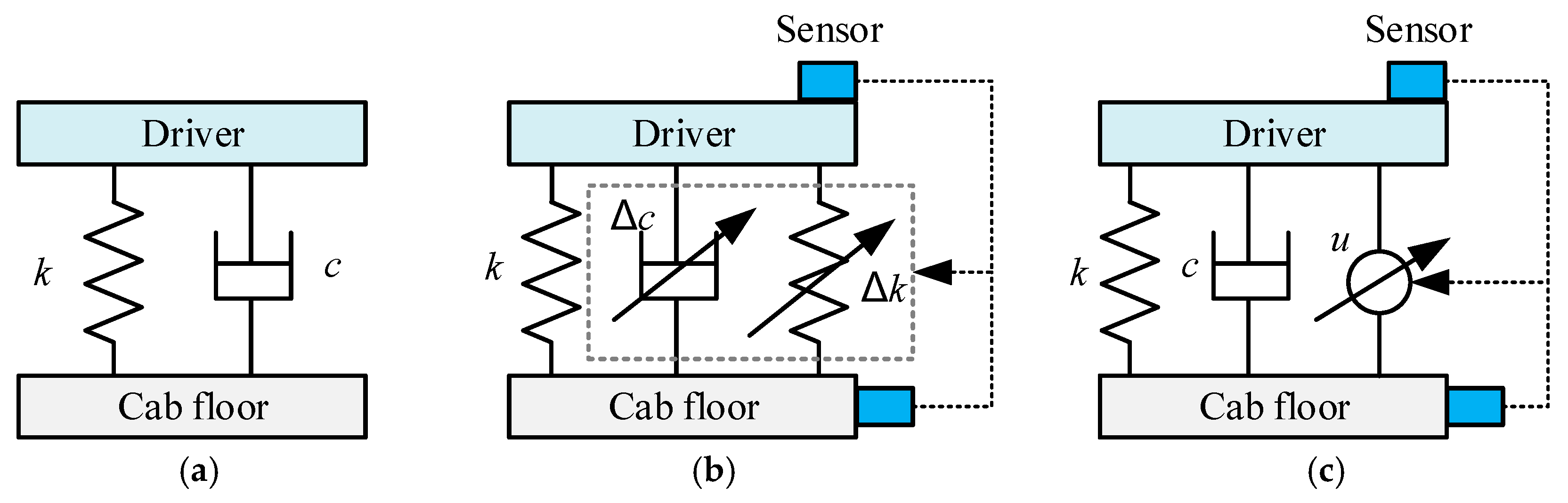
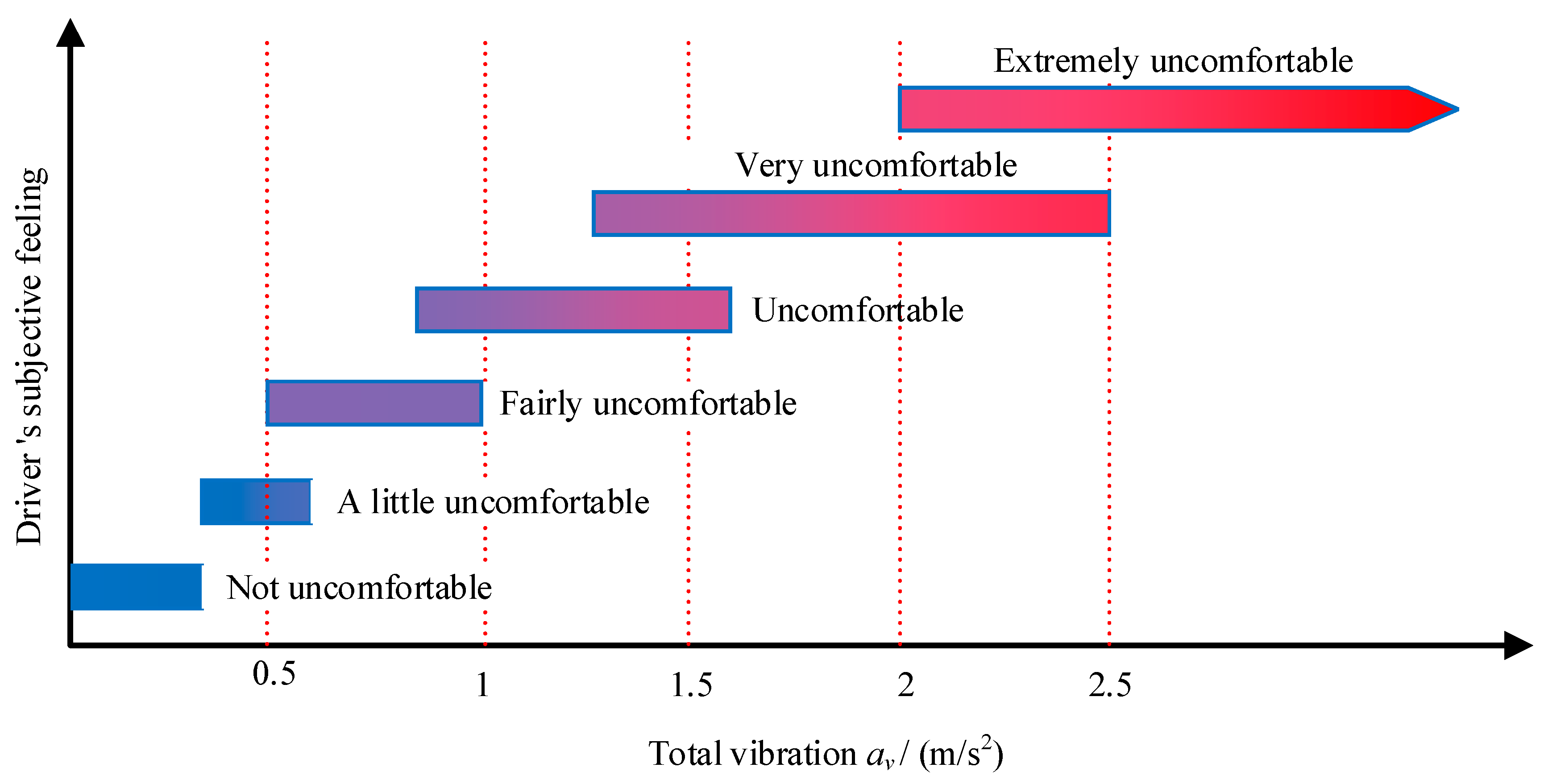

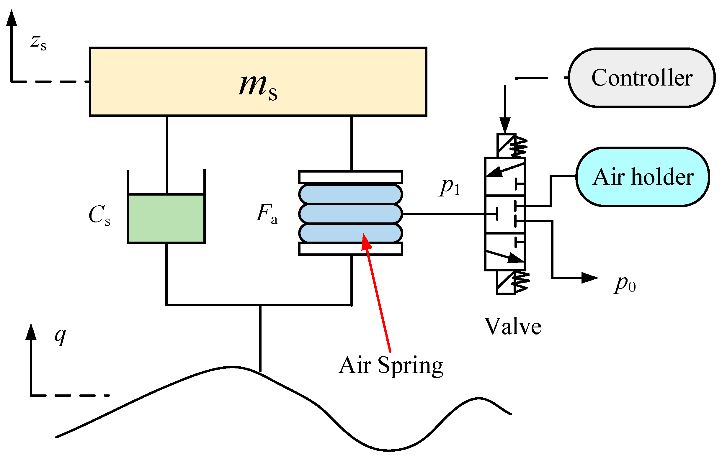
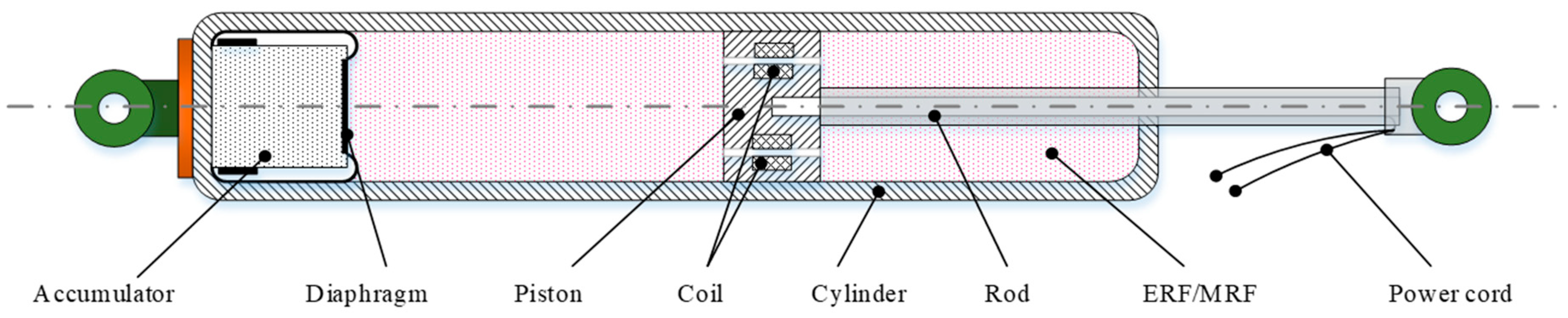
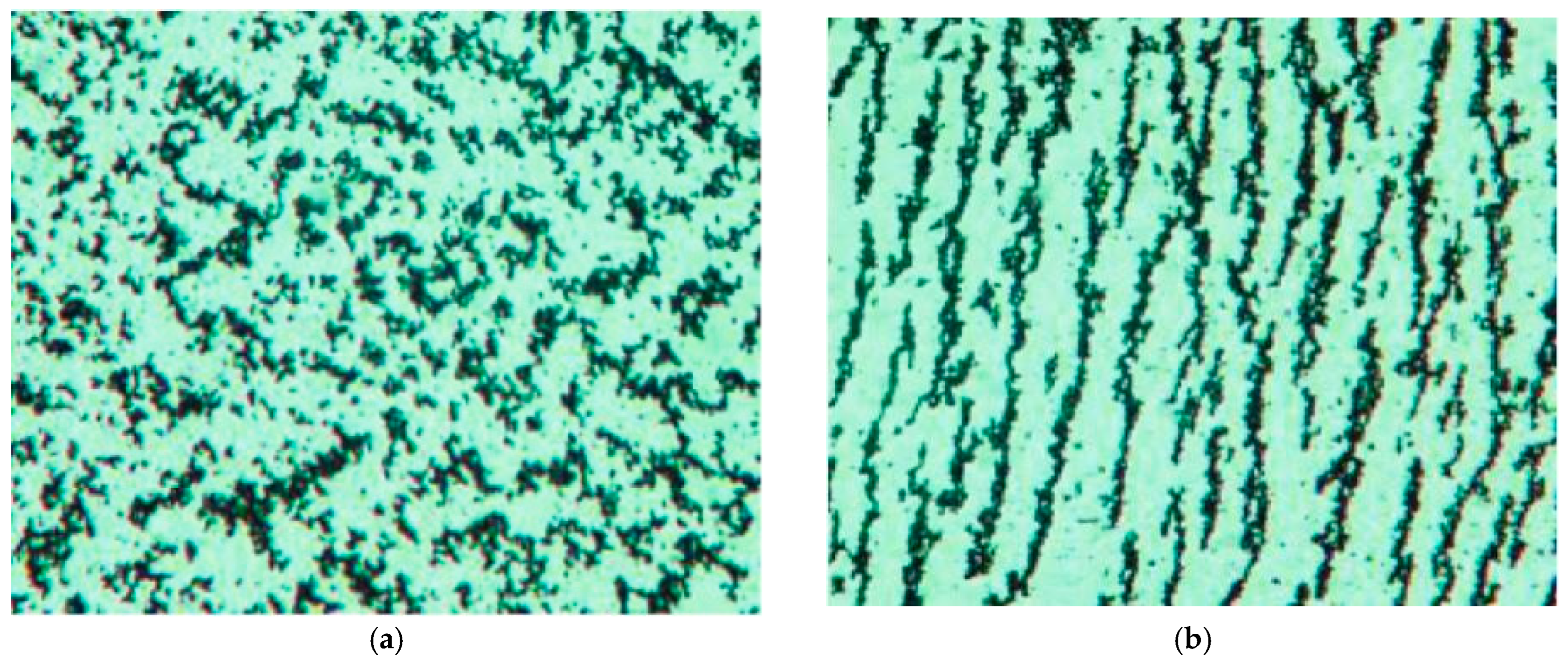
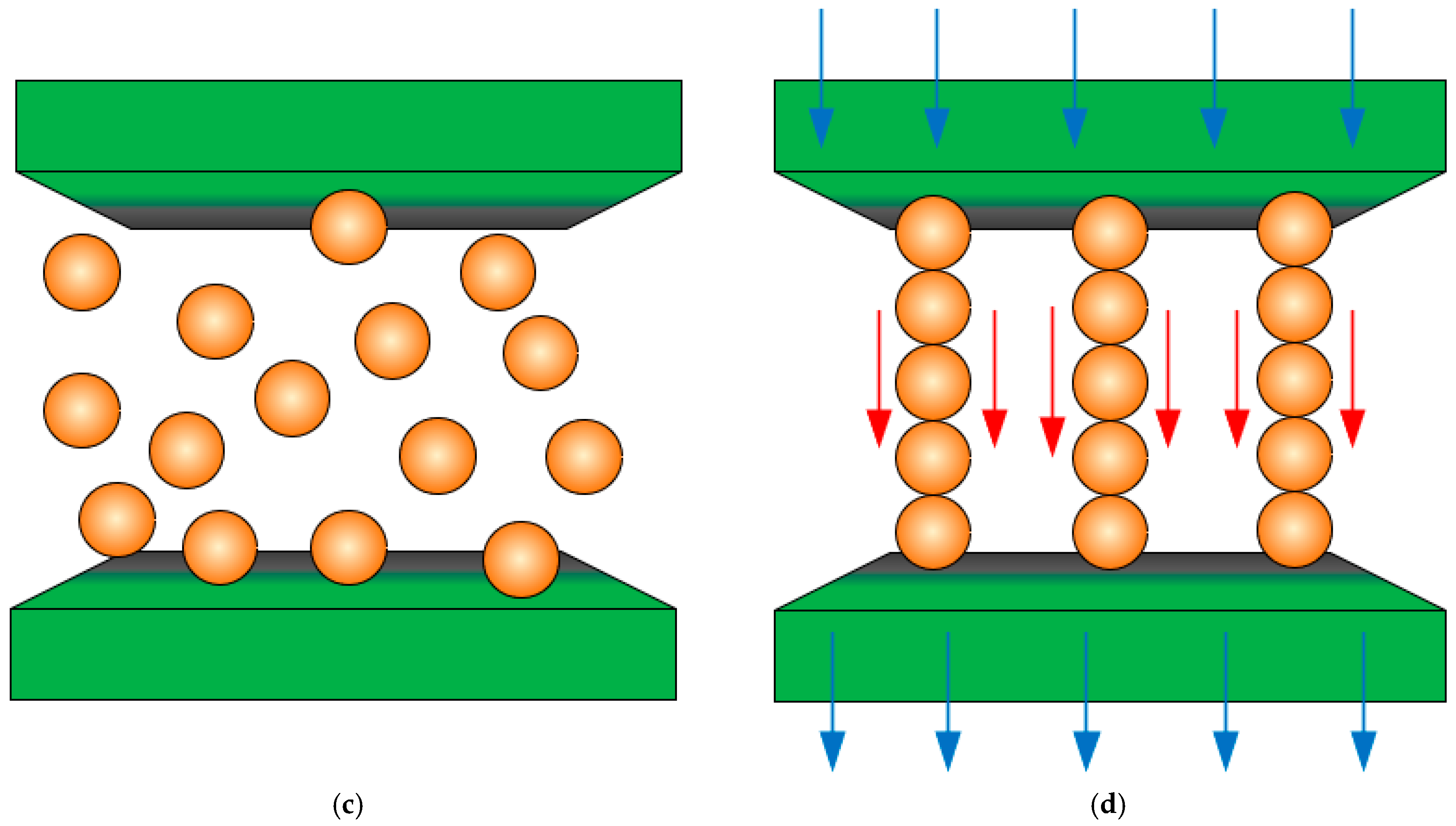
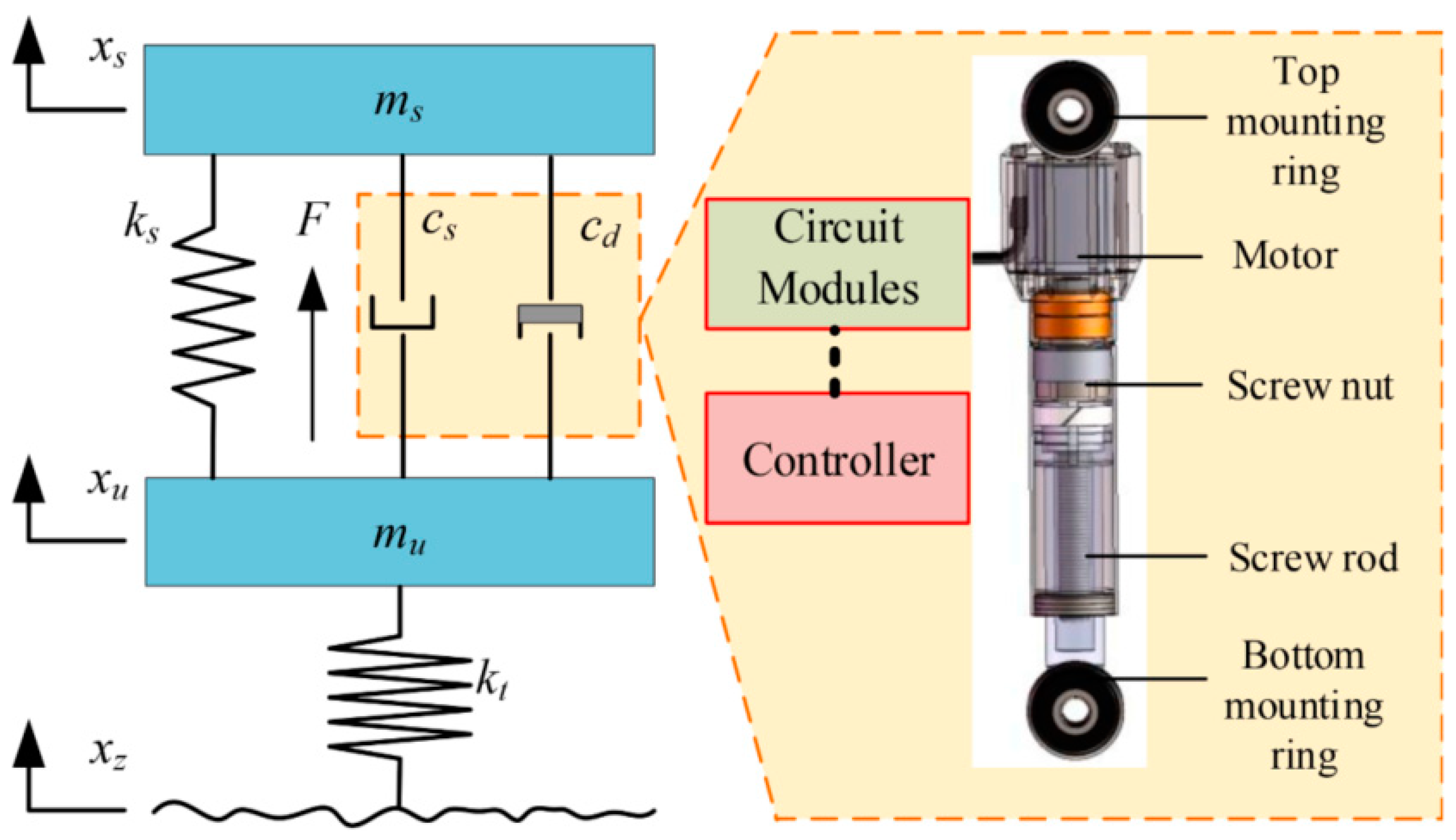
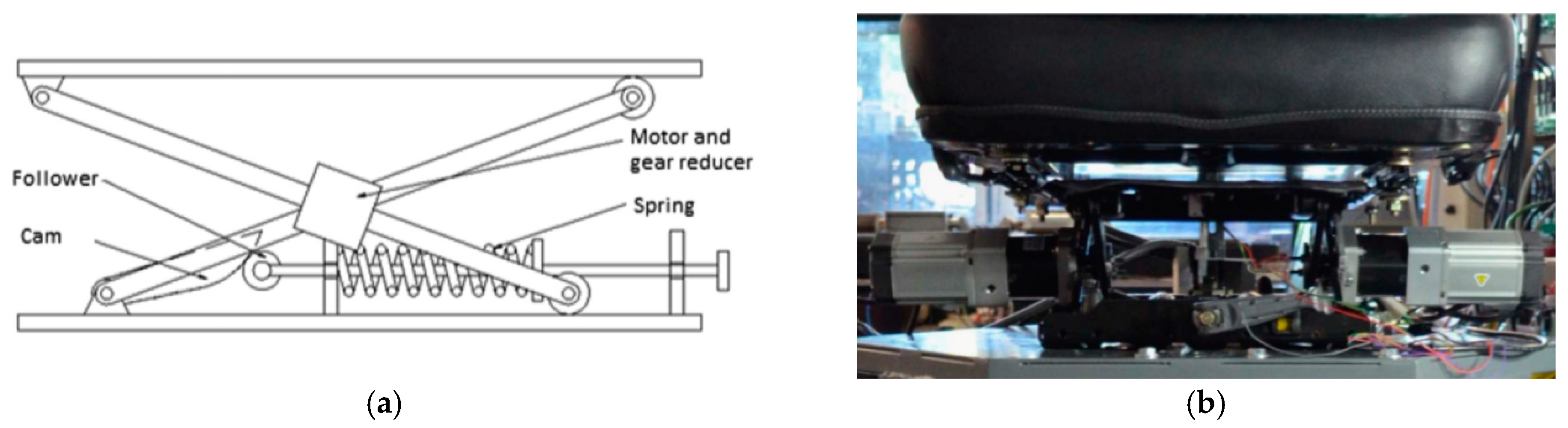

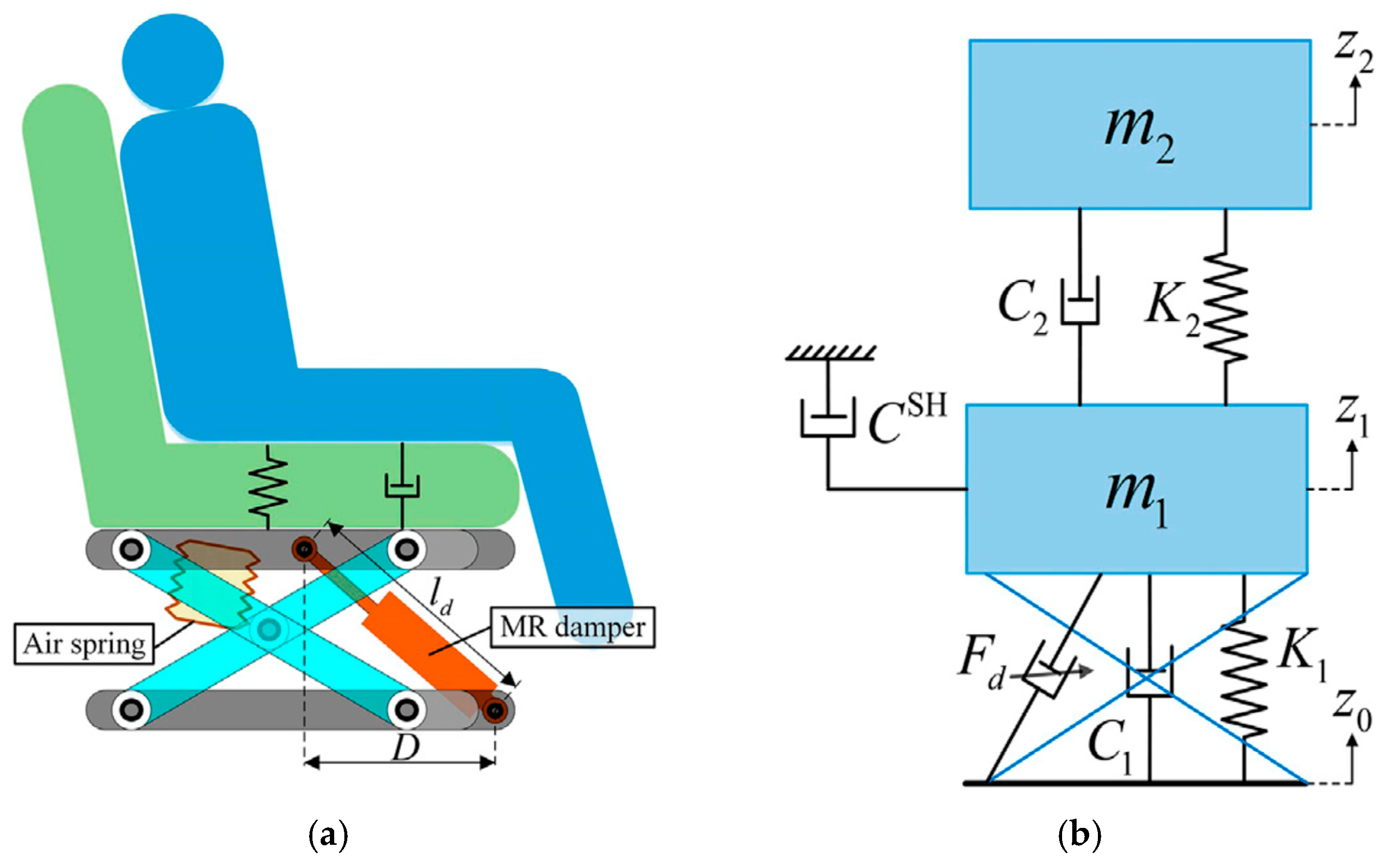
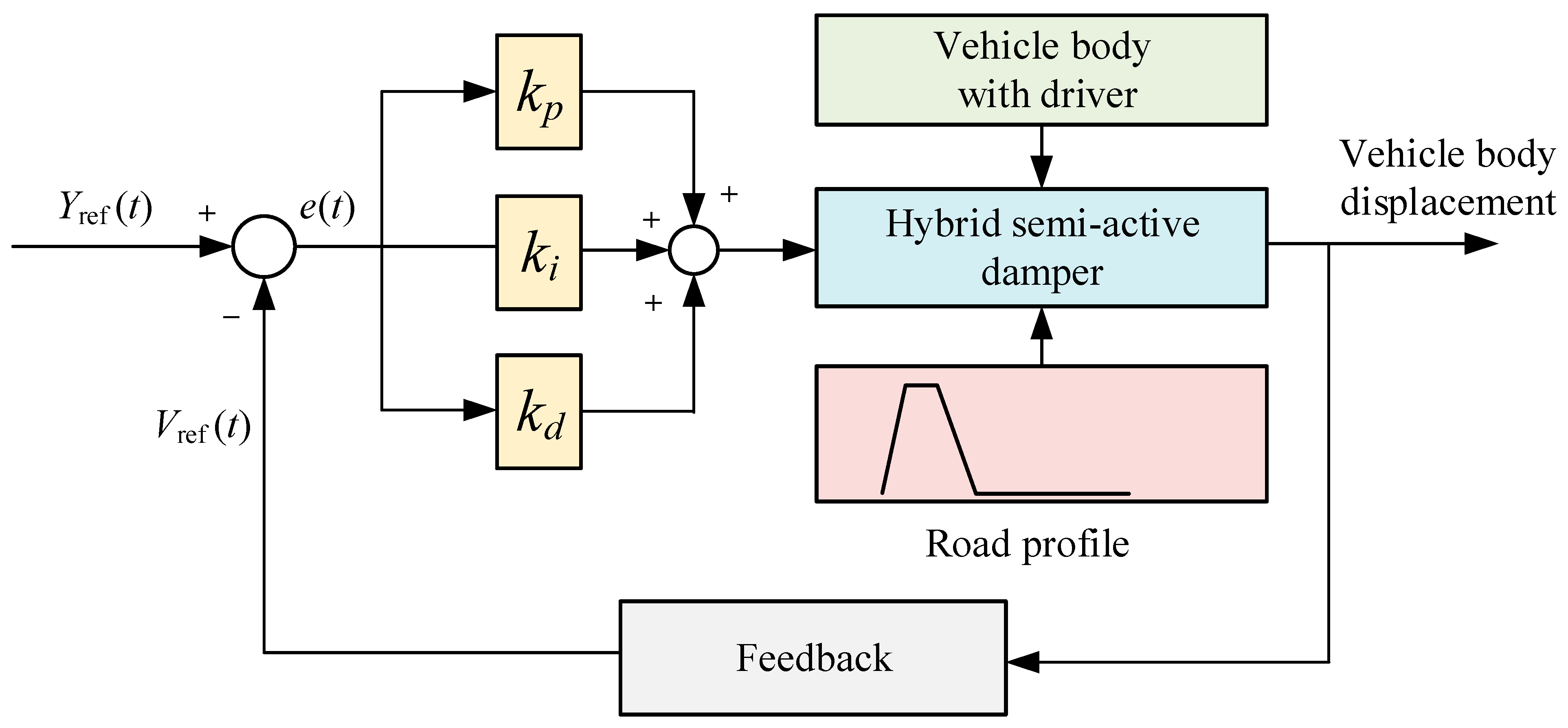
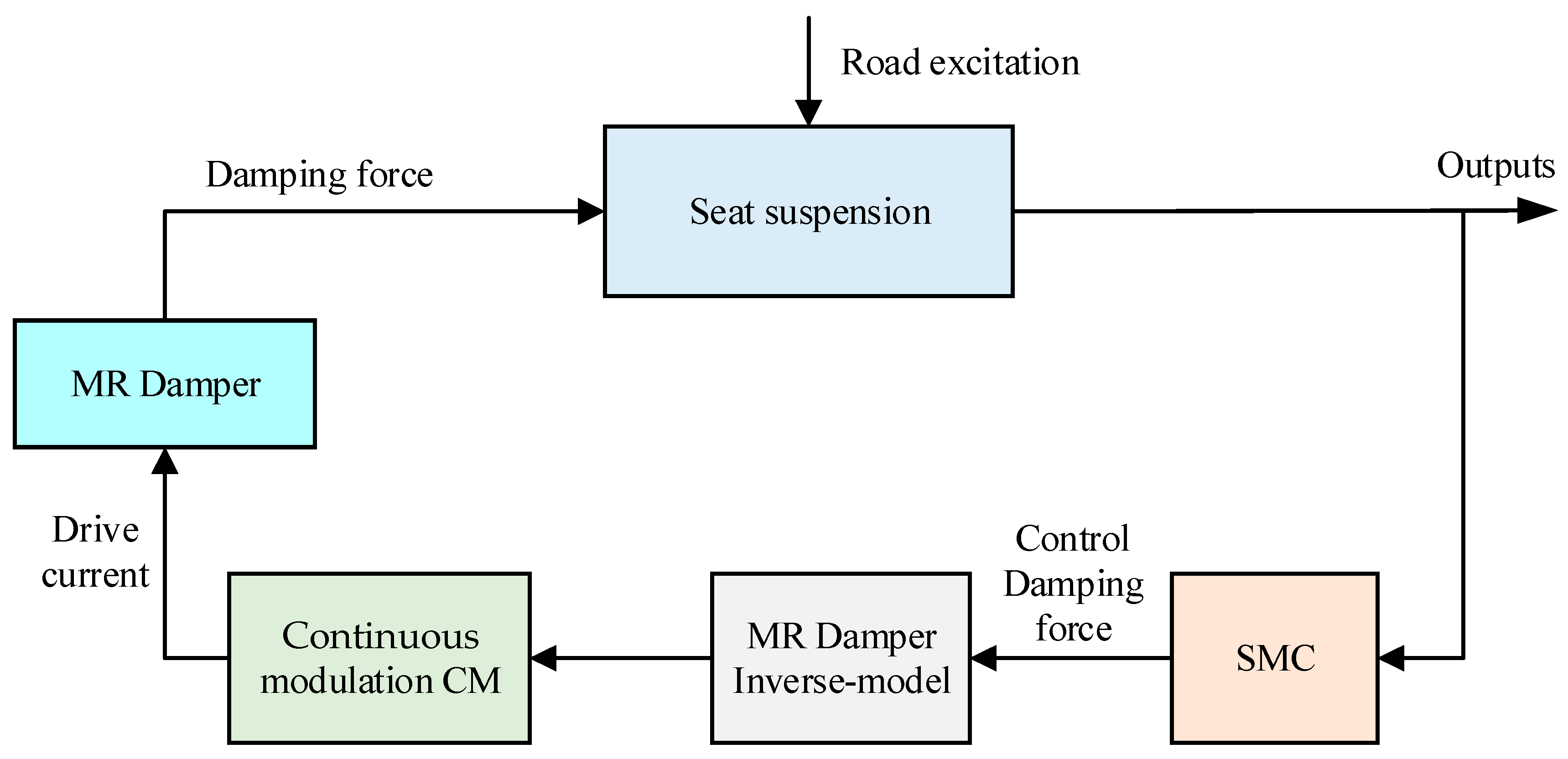
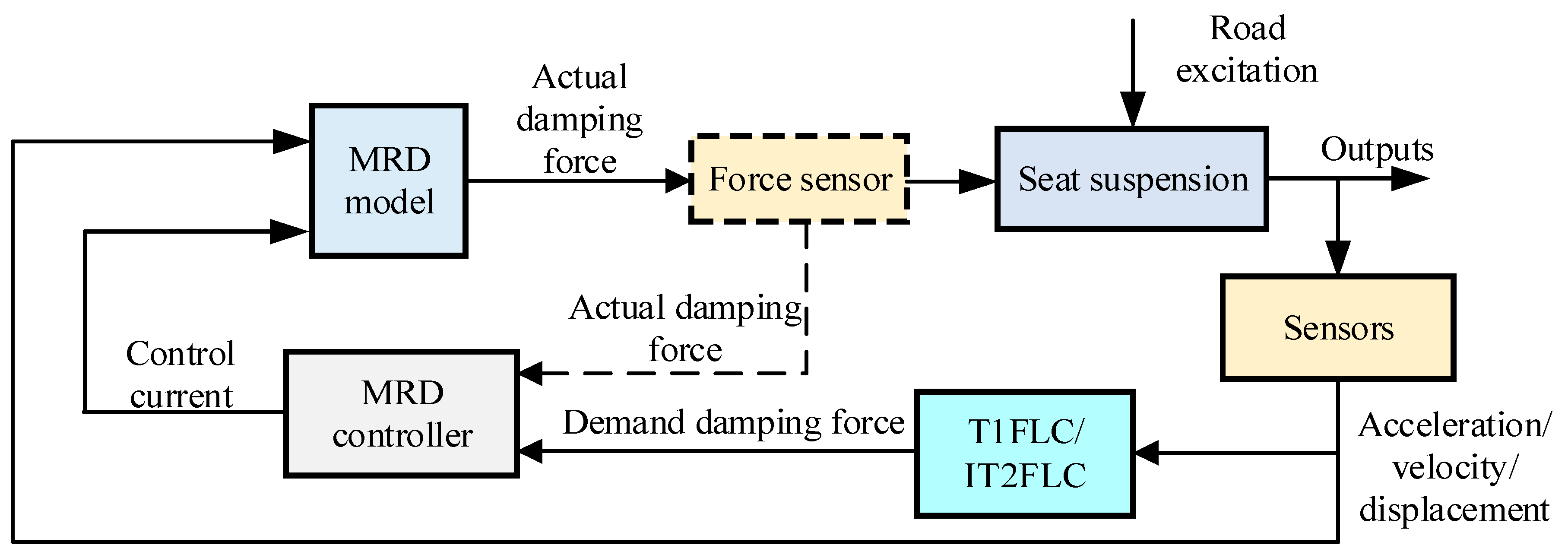

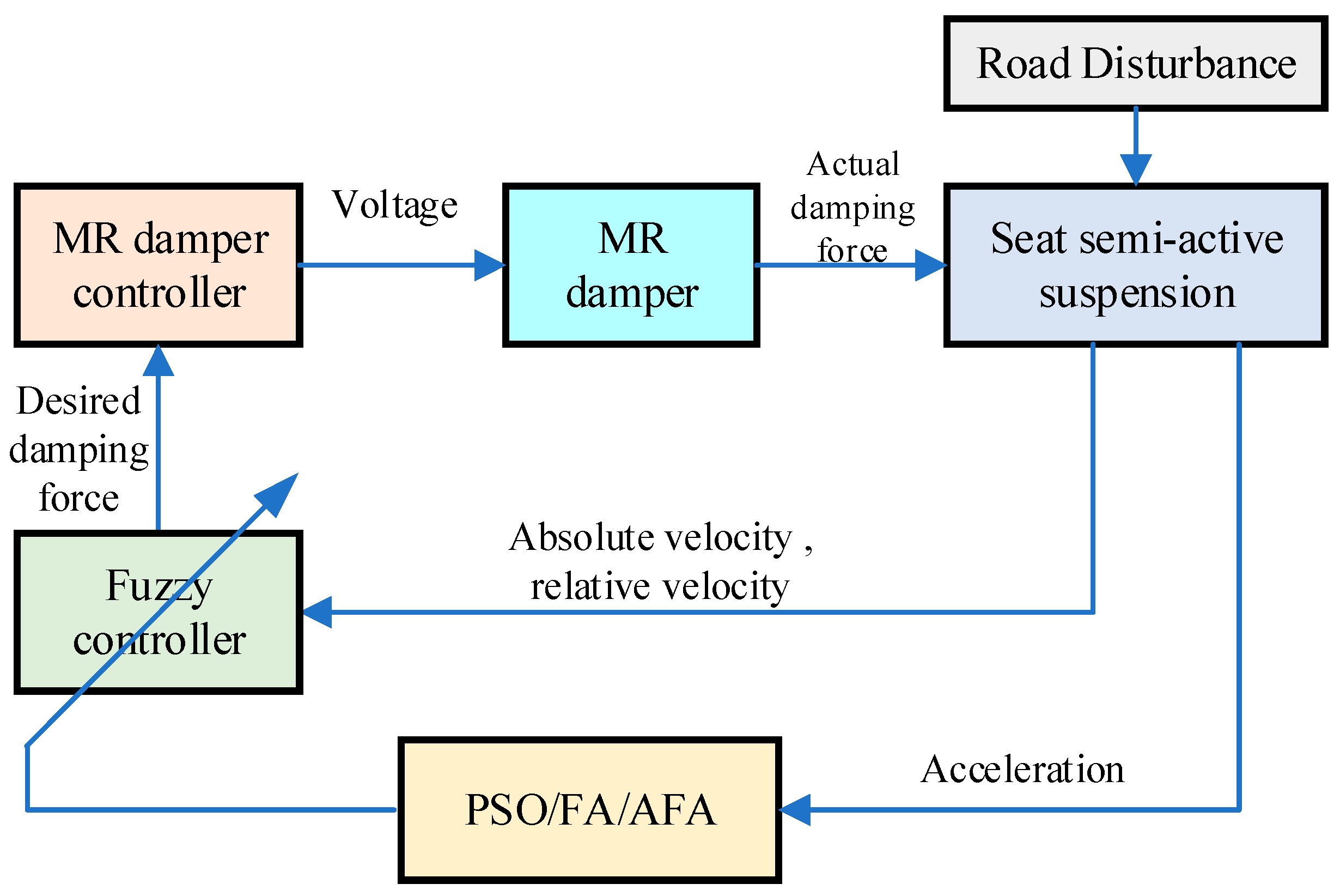
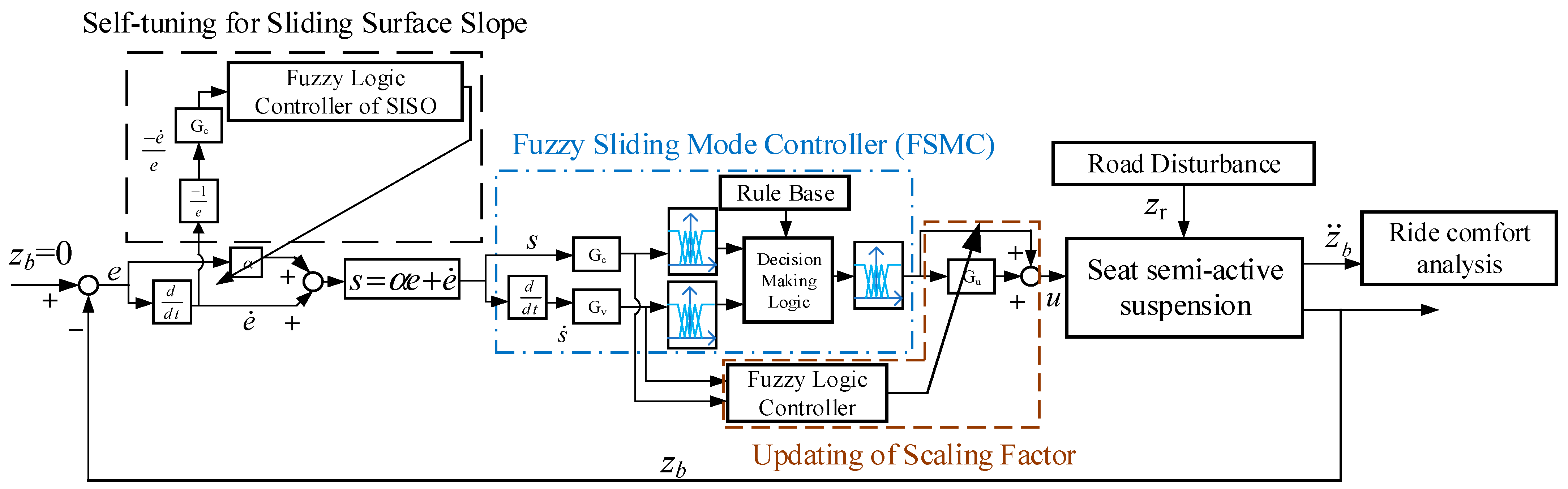
Disclaimer/Publisher’s Note: The statements, opinions and data contained in all publications are solely those of the individual author(s) and contributor(s) and not of MDPI and/or the editor(s). MDPI and/or the editor(s) disclaim responsibility for any injury to people or property resulting from any ideas, methods, instructions or products referred to in the content. |
© 2025 by the authors. Licensee MDPI, Basel, Switzerland. This article is an open access article distributed under the terms and conditions of the Creative Commons Attribution (CC BY) license (https://creativecommons.org/licenses/by/4.0/).