Article

Development and Application of a Dual-Robot Fabrication System in Figuring of a 2.4 m × 4.58 m CFRP Antenna Reflector Surface †

1
Institute of Optics and Electronics, Chinese Academy of Sciences, Chengdu 610209, China
2
School of Optoelctronic Science and Engineering, University of Electronic Science and Technology of China, Chengdu 610054, China
3
Shanghai Composites Science & Technology Co., Ltd., Shanghai 201112, China
*
Author to whom correspondence should be addressed.
This paper is an extended version of our paper published in EPJ Web Conference, Munich, Germany, 24–26 June 2019.
Machines 2025, 13(4), 268; https://doi.org/10.3390/machines13040268
Submission received: 4 February 2025 / Revised: 12 March 2025 / Accepted: 19 March 2025 / Published: 25 March 2025
(This article belongs to the Section Advanced Manufacturing)

Abstract

:
The demand for large-scale components continues to grow with the development of frontier technologies. Traditionally, these components are machined using machine tools, which are costly and have functional limitations. High-flexibility robots provide a cost-effective solution for machining large-scale components. This research proposes a dual-robot fabrication system for producing a 2.4 m × 4.58 m carbon fiber reinforced polymer (CFRP) antenna reflector. First, the kinematic model of the in-house developed robot was established to compute its theoretical workspace, which was subsequently used to partition the machining regions. Based on laser tracker measurements and theoretical calculations, a method and procedure for calibrating the Tool Center Point and Tool Control Frame of the robot were proposed. Subsequently, the dual-robot fabrication system was configured based on the determined machining regions for each robot. To further improve the figuring accuracy of the system, the support structure and figuring path were investigated and determined. Finally, processing experiments were conducted, and the material removal function for the flexible processing tool was computed to shape the reflector surface. The final results achieved the required surface figure accuracies for areas ≤ φ1750 mm, ≤φ2400 mm, and the whole surface were improved to 13.5 μm RMS, 23.4 μm RMS, and 45.8 μm RMS, respectively. This validates the processing capability and demonstrates the potential application of the dual-robot fabrication system in producing large-scale components with high accuracy.

1. Introduction

With the development of technology, the size of components is continuously increasing to achieve the required properties, such as ground-based or space-borne observation telescope mirrors and antenna reflectors. To obtain the required sensitivity and angular resolution in astronomy and astrophysics, the Giant Magellan Telescope (GMT) was proposed [1,2]. It is a 25-m telescope comprising seven 8.4-m mirrors [3]. The European Extremely Large Telescope (E-ELT) features a 39-m segmented primary mirror (M1), a 4-m convex secondary mirror (M2), and a 4-m concave tertiary mirror (M3) [4]. For space-borne antennas, increasing the collecting area is an effective method for achieving higher resolution [5]. Some space-borne antennas may even reach 20 or 30 m, such as the 22-m SkyTerra-1 Mesh Reflector and the 34-m Exo-S Starshade [6].
The increase in the aperture size of optical elements and antenna reflectors inevitably leads to an increase in weight. Consequently, carbon fiber reinforced polymer (CFRP), known for its light weight, high strength, and corrosion-resistant properties, has become the material of choice for manufacturing antenna reflectors, garnering considerable attention from researchers [7,8]. To further reduce weight, CFRP components often employ honeycomb sandwich structures, combined with extremely low thickness-to-diameter ratios, which significantly reduce the overall rigidity of the workpiece, making it prone to deformation. Due to the high hardness and high modulus of CFRP, along with the viscoelastic properties of its surface resin, traditional machining methods such as tool cutting and bonded abrasive processing are prone to issues such as tool clogging, wear, and resin peeling [9]. Furthermore, the resin matrix’s low glass transition temperature requires strict control of the temperature rise in the processing area [10] As the size of the components increases, the problems of tool damage and insufficient tool life become more pronounced, resulting in greater safety risks and challenges in maintaining manufacturing precision.
Deformation presents another significant challenge in the development of CFRP antenna reflectors. The extent of deformation is influenced by various factors, including self-weight, the sandwich honeycomb layout, panel thickness, support stability, and environmental conditions. It is, however, indisputable that as the antenna size increases, the likelihood of deformation also increases [11], thereby significantly complicating the manufacturing process for large-diameter antenna reflectors. Consequently, most applications utilize sub-aperture stitching techniques to construct large-diameter antenna reflectors [12] While CFRP reflectors with precision levels of up to 10 microns have been achieved for meter-scale antennas [13], reports on the processing accuracy of monolithic carbon fiber antennas exceeding 4 m in size remain rare.
Therefore, addressing the ultra-precision manufacturing of CFRP antenna reflectors under the unique constraints of large aperture, low rigidity, and material-specific properties has become a key technological challenge restricting the performance of application systems.
Flexible and cost-effective robots provide an optimal solution to this problem, making robotic machining a highly promising method for replacing high-cost CNC machine tools with equivalent machining capabilities [14,15,16]. A 30–50% reduction in total costs occurs when robots replace equivalent CNC machines [17,18,19]. As the component size increases, the more cost-effective the robots become. Furthermore, robots exhibit excellent programmability, adaptability, and flexibility in contrast to CNC machine tools. These advantages of multifunctional robots have led to a dramatic increase in their industrial application over the past 30 years [20,21]. The demand for efficiently figuring large and complex aspheric components has motivated the replacement of CNC machine tools with robots [22,23].
Therefore, robot-assisted surface figuring (RSF) technology with high accuracy was proposed and developed, and significant efforts have been made to advance this technology. Wang et al. reported the use of low-cost industrial robots in deterministic surface figuring of optical surfaces, where the surface accuracy was comparable to that produced by a CNC polishing machine [22]. Li et al. proposed a non-Newtonian Silly Putty tool combined with a specially designed random tool path to remove mid-spatial frequency tool marks with an industrial robot. The results indicated that these marks were effectively removed from an aluminum mirror [24]. Yao et al. studied the effect of material removal functions on surface form accuracy convergence using RSF, showing that the M-like removal function exhibited superior convergence speed compared to the Gaussian-like removal function [25]. Wan et al. proposed a figuring path planning method that could adapt to the surface form accuracy for RSF. With this method, areas with larger form errors were corrected without affecting other areas, as in manual polishing. This reduced both the polishing time and errors resulting from the low control accuracy of the robotic polisher [26]. Hasirden et al. measured and analyzed the positioning accuracy of the in-house developed SIAI robot, and a method for compensating positioning errors was proposed to improve the processing efficiency and accuracy of RSF in fabricating optics [27]. Liu et al. reported progress in grinding and polishing a toroid concave surface mirror and an off-axis parabolic reflective mirror using a combination of an in-house developed robot and an industrial robot. Surface shape errors improved from about PV 29 μm and RMS 3.4 μm to PV 3.4 μm and RMS 0.3 μm for the off-axis parabolic reflective mirror with a size of Φ500 mm [28]. Brooks et al. verified the capability of RSF technology in figuring an extreme freeform optical surface, achieving an RMS surface error of <0.5 μm for optics with a size of 300 mm square [29]. Although progress has been made in improving the figuring efficiency and accuracy of RSF technology, such as developing and optimizing the figuring path, proposing novel figuring tools, and improving robot accuracy, these studies are confined to relatively small components fabricated with a single robot.
In the context of CFRP antenna reflectors’ surface quality, due to the high thermal control performance requirements of the application system, surface roughness is not required to be minimized as in conventional components. Instead, the specification calls for surface roughness to be controlled within the range of 400 nm to 500 nm, utilizing localized roughness machining. Furthermore, it is essential to ensure that the surface material does not undergo performance degradation due to temperature-induced changes during processing. To address these challenges, this study proposes the use of a small tool machining technique using water-based free abrasives for the processing of CFRP antenna reflectors. In this technique, the free abrasives are dispersed in a water-based coolant environment, covering the machining area throughout the process, while the coolant is continuously replenished. The abrasives are dynamically refreshed between the tool and the workpiece surface, which facilitates efficient material removal. This method’s key advantage in CFRP machining is its ability to provide real-time replenishment of abrasives during the process, which resolves common issues such as tool wear and clogging that are typical in conventional cutting operations. Additionally, the water-based free abrasives provide simultaneous cooling to the workpiece surface, preventing material property degradation due to surface temperature rise during machining. As such, this technique is highly effective for both ultra-precision shaping and roughness correction of CFRP materials.
In this study, a flexible dual-robot fabrication system was proposed and applied to the shaping of a 2.4 m × 4.58 m carbon fiber reinforced polymer (CFRP) antenna reflector. The robots work collaboratively to shape the reflector surface in an efficient manner, which reduces both time and cost. This study is organized into sections to illustrate the establishment of the fabrication system and verify its processing capability, as shown in Figure 1. Firstly, the characteristics of the large-diameter CFRP workpiece to be processed were presented. Secondly, the characteristics of the self-developed robot were described in brief, followed by the construction of its kinematic analysis model to study its motion accuracy. The calibration methods for the tool center frame (TCF) and tool center point (TCP) were proposed, and the motion workspace of a single robot was analyzed. This analysis provided the theoretical model for the machining space, which is essential for the subsequent construction of a dual-robot multi-station platform. Next, based on the workspace analysis of the multi-station robots, a dual-robot multi-station machining device was developed. A whiffletree support mechanism was introduced to ensure reliable and stable support accuracy. After analyzing the robot operation accuracy under different trajectories, the trajectory offering the highest precision was identified as the optimal machining trajectory. Further optimization of process parameters and tools was conducted to select the appropriate abrasives for localized roughness processing, as well as flexible tools that could achieve high surface adaptability for CFRP antenna reflector machining. Finally, high-precision surface shaping of the single large-diameter, weak-rigidity CFRP antenna reflector was successfully achieved.

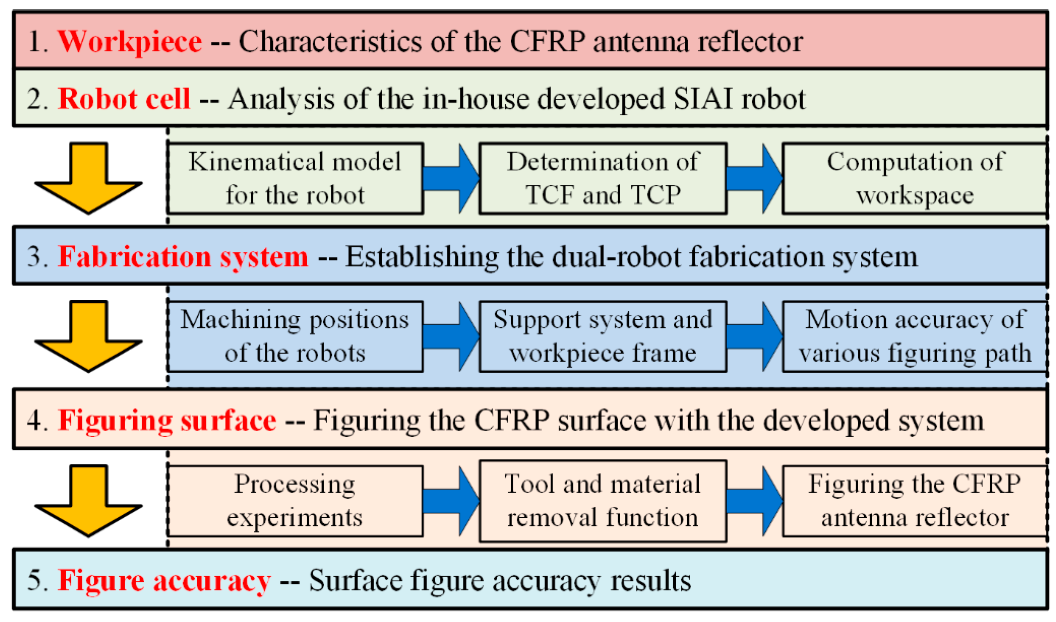
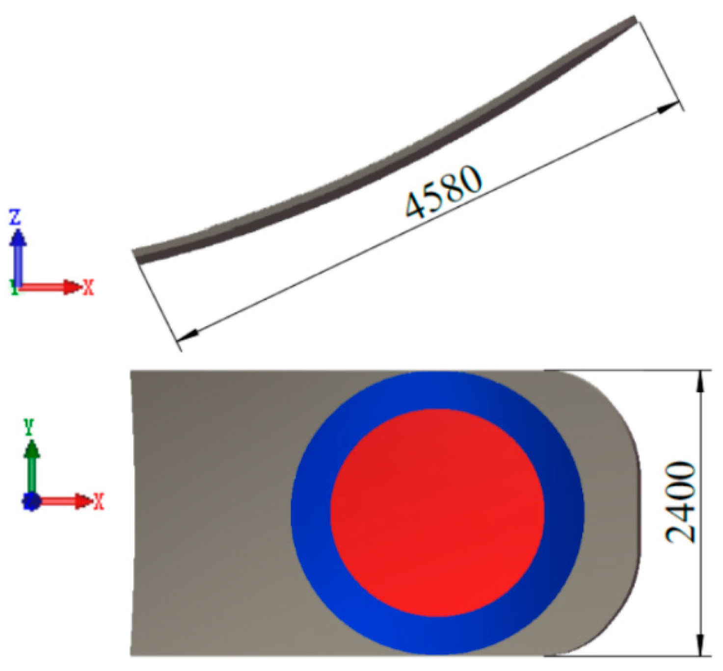
2. Characteristics of the CFRP Antenna Reflector

The antenna reflector to be shaped is made of CFRP, a material known for its excellent physical and chemical properties, including high specific stiffness, light weight, non-corrosiveness, excellent fatigue resistance, and low thermal expansion. These characteristics propose a promising solution for fabricating large, ultra-lightweight space-borne components, particularly for satellite antenna reflectors and lightweight space mirrors [30,31,32]. The inner structure of the CFRP antenna reflector is a typical sandwich structure, with both the skin and core made of CFRP. Studies show that this design offers better performance for space-borne antenna reflectors in resisting thermal deformation [31]. The dimensions of the reflector are 2400 mm × 4580 mm, with a thickness of 70 mm, as shown in Figure 2. The upper surface of the reflector is an off-axis parabolic surface, with a radius of curvature of R = 7992.296 mm and an off-axis distance of 3898.6088 mm. The surface shape can be expressed by the following equation:
z = x 2 + y 2 2 R
Surface figure accuracy is evaluated using the root mean square error (rms), and the accuracy of the reflector surface varies in different regions. The accuracies for areas ≤ φ1750 mm (shown in the red region of Figure 2), ≤φ2400 mm (shown in both the red and blue regions of Figure 2), and the entire surface are 15 μm rms, 30 μm rms, and 90 μm rms, respectively. Due to thermal control requirements, the surface roughness was specified to be between 400 nm and 500 nm for the entire surface.

3. The In-House Developed SIAI Robot

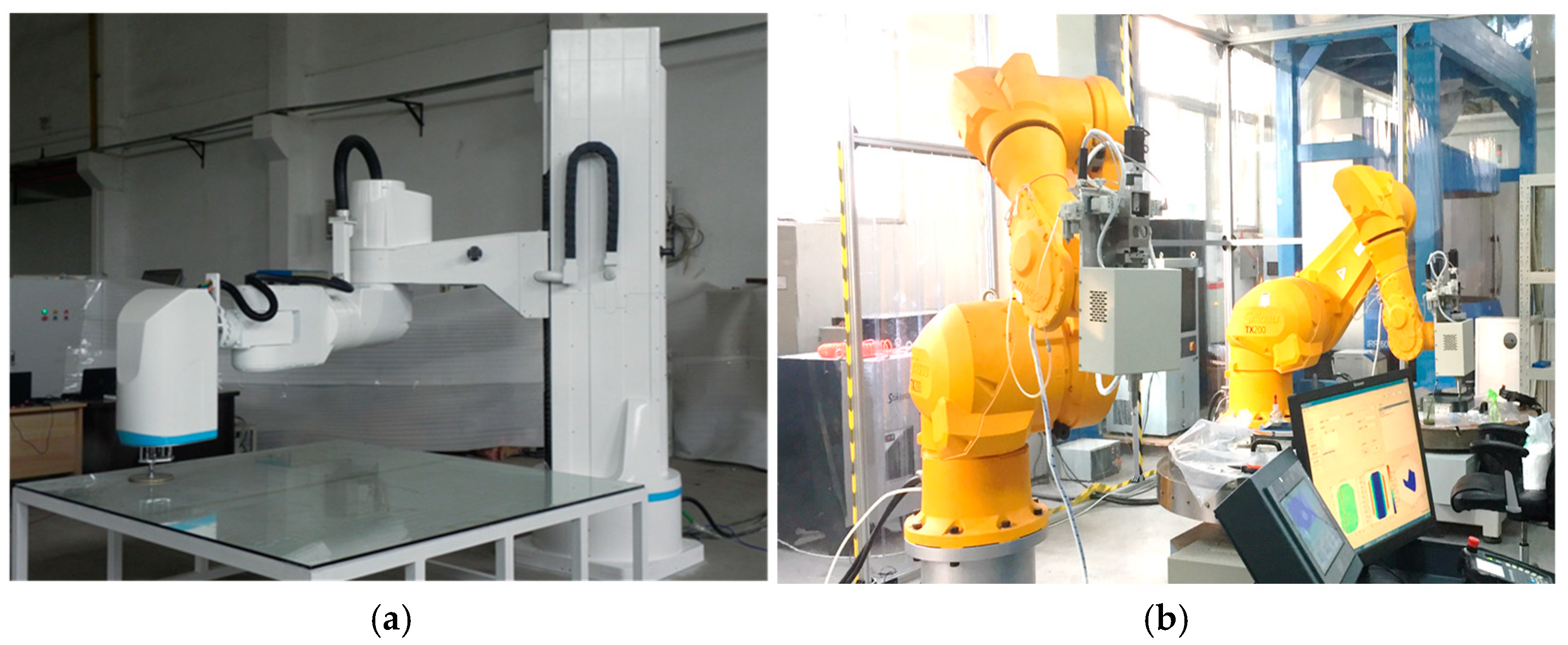
3.1. Overview of SIAI Robot

To achieve the figuring of large components, such as the CFRP antenna reflector, and meet the requirements for fabricating large free-form optics that may scale up to meters or even tens of meters in the future, the Institute of Electronics and Optics (IOE) has developed surface figuring systems based on either in-house developed robots or industrial robots. Figure 3 illustrates the large and medium-scale optical fabrication systems, which are based on the in-house developed SIAI robot (Institute of Optics and Electronics, Chinese Academy of Sciences, China, and The Smartech Institute, China) and the industrial Stäubli robot (Stäubli, Pfäffikon, Switzerland). The SIAI robot is designed to process meter-scale optical components, with the capability to shape components up to 2 m in size. This robot will be used to figure the CFRP antenna reflector. The SIAI robot features a six-degree-of-freedom (DOF) serial structure with a 5R-1D configuration, with axes 1, 3, 4, 5, and 6 being rotational, while axis 2 is translational, as shown in Figure 4. The robot’s main body includes key components such as a cast iron frame, reduction gearboxes, servo motors, and control cables. Its tool frame is defined at the bottom center of the polishing tool, as shown in Figure 4. The position of the polishing tool is determined by the movements of joints 1 (J1), 2 (J2), and 3 (J3). The orientation of the tool is adjusted by joints 4 (J4), 5 (J5), and 6 (J6). By manipulating the offsets and angles of joints J4, J5, and J6, the Z-axis ( Z T ) of the tool can be made perpendicular to the component surface. In this way, the polishing tool can be adaptively adjusted according to the curvature of the component surface to be figured.
Table 1 presents the detailed Denavit–Hartenberg (DH) link parameters of the SIAI robot. The kinematic model of the SIAI robot was established based on the parameters presented in Table 1, along with the forward kinematic equations [33].
T 6 0 = 1 0 T 2 1 T 3 2 T 4 3 T 5 4 T 6 5 T
The kinematic model was constructed using the numerical calculation software MATLAB R2016, and the theoretical calculation of motion position accuracy was performed, excluding the influence of other nonlinear factors. To evaluate the accuracy of the established numerical model, 10 coordinate positions (xe, ye, ze) of the end effector, along with the corresponding joint angles and offsets ( θ 1 , d 2 , θ 3 , θ 4 , θ 5 , θ 6 ), were recorded using the teach pendant. The theoretical positions of the end effector (xet, yet, zet) were subsequently computed using the kinematic model of the SIAI robot. The position errors between the results obtained from the teach pendant and those predicted by the kinematic model are shown in Figure 5. The results demonstrate that the errors in the x, y, and z coordinates are within ±0.005 mm, which is acceptable. Therefore, the positions obtained from the established kinematic model correspond to those obtained from the robot controller, verifying the model’s accuracy. This lays the foundation for calibrating the coordinates and evaluating the motion accuracy of the robot.

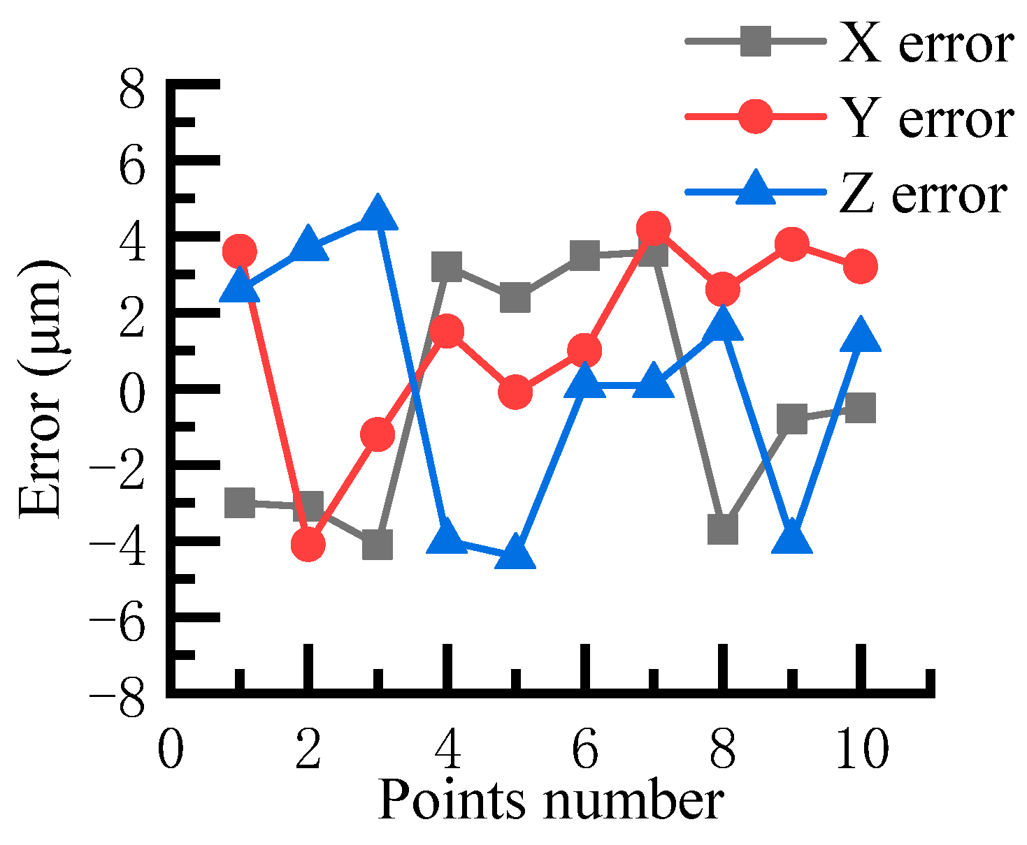
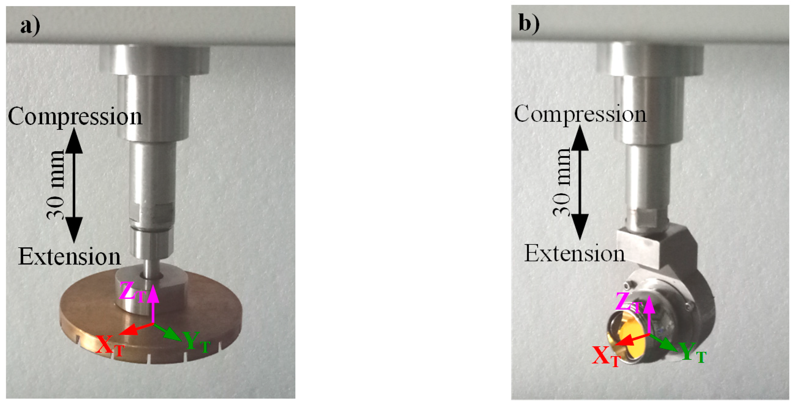
3.2. Determination of the Tool Center Point and Tool Control Frame

When preparing the processing program, it is essential to refer to a specific point on the end effector to plan and generate the tool path. The point is usually located at the bottom center of the tool and is called the tool center point (TCP). TCP is always taken as the origin of the tool control frame (TCF). Since the tool is an additional apparatus attached to the robot, it can be considered an extension of the flange, as shown in Figure 4. This implies that the TCF is isolated from the robot and is not strictly aligned with the flange frame F . It is necessary to determine the TCF under the base frame before determining the TCP. The accuracy of the TCP and TCF will impact the surface accuracy, which is stringently required in the figuring of the CFRP antenna reflector.
To calibrate and determine the TCP and TCF, a high-precision laser tracker was employed. To calibrate the TCP, the laser tracker calibration can quickly determine the TCP with only one posture, provided the reference point coordinates are known under the base frame of the robot. Compared to the least squares method and the four-point method, which require several postures to calibrate the TCP, this method is easier to implement. To determine the TCF, the end of the tool is a pneumatically driven telescopic link with an extension range of approximately 0–30 mm, as shown in Figure 6. This allows the tool to flexibly engage with the component surface. This feature can also be used to determine the TCF. We propose a method to determine the TCP and TCF by combining this feature with laser tracker measurements. The API Tracker3 (Automated Precision Inc., Rockville, MD, USA) was employed in our research. Its absolute accuracy in 3D spatial measurement in static and dynamic modes is 5 ppm and 10 ppm, respectively, which satisfies the measurement requirements. The spherical mounted retroreflector (SMR) was connected to the processing tool using a specially designed SMR base, as shown in Figure 6a. This base ensures that the center of the SMR aligns with the center of the polishing tool when mounted, as shown in Figure 6b.
Procedure for determining the TCP and TCF:
  • Mount the base and SMR on the end of the polishing tool.
  • Measure and set up the robot’s base frame using a laser tracker.
  • Adjust the posture and orientation of the robot, deactivate the air valve, and ensure the telescopic link is in a contracted state. Record the joint parameters and the corresponding SMR position   ( x 1 , y 1 , z 1 ) .
  • Activate the air valve and ensure the telescopic link is in an extended state. Record the joint parameters and the corresponding SMR position ( x 2 , y 2 , z 2 ) .
The measured SMR position vector under the robot’s base frame B can be expressed as follows:
P i T B = x i y i z i , i = 1,2
where P i T B represents the SMR position vector under the robot frame B . Based on the SMR position ( x 1 , y 1 , z 1 ) , the TCP vector under the flange frame F , denoted as P T F , can be obtained from the following equation:
P T F = x t y t z t 1 = T 1 F B · x 1 y 1 z 1 1
where T 1 F B represents the inverse of the posture and orientation of the joints under F .
The Z-axis of the polishing tool is defined by the axis of the telescopic link. In figuring the CFRP antenna reflector, only the axis of the polishing tool perpendicular to the reflector surface is required, and the posture and orientation of the Z-axis should be determined. Using the method of X-Y-Z fixed angles, the Z-axis vector of the tool under F   can be obtained by utilizing the SMR positions ( x 1 , y 1 , z 1 ) and ( x 2 , y 2 , z 2 ) through the following equation:
Z T F = x t z y t z Z t z 1 = T 1 B F · x 2 x 1 y 2 y 1 z 2 z 1 1
According to the relations shown in Figure 7, the coordinate’s transformation between rotation angle of rx, ry, and Z-axis could be computed using
r x = arcsin y t z / y t z 2 + z t z 2
r y = arcsin x t z / x t z 2 + y t z 2 + z t z 2
The X and Y axes of the tool are not required in fabricating the CFRP antenna reflector, so r z = 0 . According to the method of X-Y-Z fixed angles and combining Equations (5)–(7), the rotation matrix of TCF can be written as follows:
R T F = 1 0 0 0 cos ( r x ) sin ( r x ) 0 sin ( r x ) cos ( r x ) · cos ( r y ) 0 sin ( r y ) 0 1 0 sin ( r y ) 0 cos ( r y )
The TCF can finally be obtained:
T T F = R T F Z T F 0 0 0 1

3.3. Workspace for a Single SIAI Robot

It is crucial to compute the workspace of a single SIAI robot before further planning the machining region of the fabrication system. The workspace was computed using the inverse kinematic model, which can be established based on the parameters presented in Table 1. The computed workspace is divided into vertical and horizontal ranges. The height of the CFRP surface to be machined is approximately 300 mm, which is considerably smaller than the robot’s vertical range (d2 = 909 mm). For simplicity, only the horizontal range of the robot was analyzed in planning its positions. Figure 8a illustrates a comparison between the reflector dimensions and the robot’s workspace when the robot is positioned at (−2000, 0). The blue dots represent points within the robot’s workspace, while the red crosses indicate points outside of the workspace. Together, the blue dots and red crosses form the entire surface of the antenna reflector. Since the dimensions of the reflector exceed the workspace of a single SIAI robot, it was essential to understand the robot’s workspace for the subsequent planning of machining positions and dividing the CFRP surface for processing by robots positioned differently. As shown in Figure 8a, a small region near the robot cannot be processed. To cover this region within the workspace, the robot must move away from the reflector. The robot is moved to position (−2600, 0), and the resulting computation is shown in Figure 8b.
In summary, this section develops a kinematic model of the robot to compare the actual motion accuracy with theoretical predictions, thereby ensuring that the robot’s basic operational position accuracy satisfies the machining precision requirements. Additionally, an effective method for determining the robot’s tool center frame (TCF) and tool center point (TCP) is proposed, which provides technical support for selecting tool machining parameters in subsequent processes. Furthermore, based on the constructed model, the workspace of a single robot is analyzed, offering both a theoretical foundation and computational model to support the optimization of robot and workstation layout in future planning.

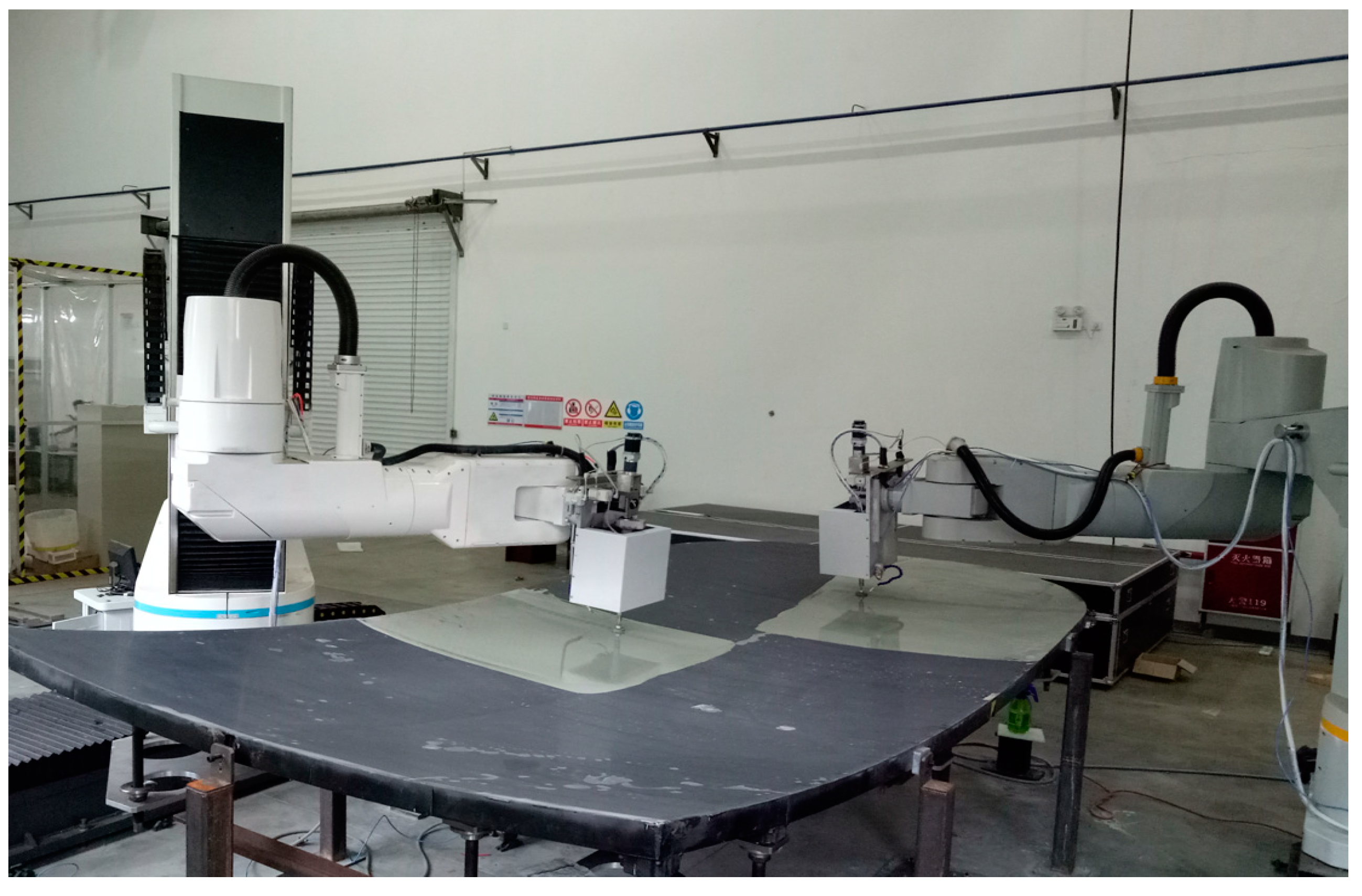
4. Development of the Dual-Robot Fabrication System

From the analysis of the workspace of a single SIAI robot, it is evident that the workspace of the robot is much smaller than the dimensions of the reflector surface. Therefore, to achieve the fabrication target, the reflector surface was divided into several regions, which were then processed by two SIAI robots positioned at different locations. The two robots were symmetrically positioned on either side of the reflector, thus requiring machining positions to be determined only for one robot. This section presents the determination of machining positions for each robot. Additionally, the properties of the component support system and surface figuring path are investigated. Finally, the dual-robot fabrication setup is established for figuring the CFRP antenna reflector surface.

4.1. Figuring Positions for the SIAI Robots

To calculate the workspace of the SIAI robot at various machining positions, the kinematic model presented in Section 3 can be extended to include multiple machining positions. Figure 9a illustrates the robot’s workspace when figuring the reflector surface with two positions. As shown in Figure 9a, the effective workspace of the robot with two positions can cover half of the reflector surface, but it is near the machining limit for a single SIAI robot. It is known that the robot’s stiffness and stability may decrease when it operates with its arm fully extended or near its limits. Therefore, it is preferable for the robot to perform figuring tasks within its optimal stiffness range [34]. Consequently, additional machining positions were introduced to allow the robot to machine the reflector surface. Figure 9b shows the workspace of the SIAI robot when figuring the reflector surface with three positions. As shown in Figure 9b, the robot with three positions can effectively cover half of the reflector surface, and it is relatively safe to machine the reflector surface under this condition.
Two SIAI robots were employed to collaboratively machine the reflector surface. The robots were symmetrically mounted on the rail guides adjacent to the antenna, as shown in Figure 10a. Each robot machined one half of the antenna’s surface. They were positioned at different locations on the rail guides to complete the fabrication process. The positions for each robot were determined using the kinematic model for robots with multiple positions, as described earlier. Figure 10b shows the machining positions of each robot. RA1, RA2, and RA3 denote the machining regions for SIAI Robot No. 1, while RB1, RB2, and RB3 denote the machining regions for SIAI Robot No. 2. A1, A2, A3, B1, B2, and B3 denote the corresponding surface figuring regions.

4.2. Support Structure for the CFRP Antenna Reflector

Lightweight components are subject to deformation due to mechanical loading, such as their own weight, which can influence the final accuracy of the surface geometry. Researchers have focused on optimizing the topology of support structures to enhance their performance in reducing surface deformation during the fabrication process [35,36]. The CFRP reflector has a thickness of only 70 mm, which is significantly smaller compared to its dimensions of 2400 mm × 4580 mm. This results in a low stiffness of the component, leading to significant deformation during surface figuring. Therefore, the design of the support structure is critical and must satisfy the required support criteria. The support structure employed in the surface figuring process is also carefully evaluated. The whiffletree support structure is effective for fabricating large-scale, thin mirrors with minimal deformation [37]. Therefore, a whiffletree support structure with 18 support points was employed to machine the reflector, as shown in Figure 11a. Each support point can be individually adjusted to achieve the required force as specified in the design. The forces applied to the supporting points were simulated using the finite element method to ensure that the surface deformation caused by gravity did not exceed 5 μm. The simulated results indicated that the surface deformation was 4.22 μm RMS under this support condition. Figure 11b presents the simulated forces and measurements at the support points. It can be observed that the measured results are in good agreement with the simulated results. Therefore, the results of the whiffletree support structure meet the design requirements and are suitable for figuring the reflector surface.

4.3. Work Frame for Figuring the CFRP Antenna Reflector

The relationship between the workpiece frame and the base frame must be established prior to planning the path for figuring the reflector. The coordinate transformation between the workpiece frame and the base frame is detailed in the research of Wang et al. [22], which can be utilized to obtain the required transformation. Since the relationship between the workpiece frame and the base frame varies when robots are positioned at different machining locations, six transformations must be determined for each position.

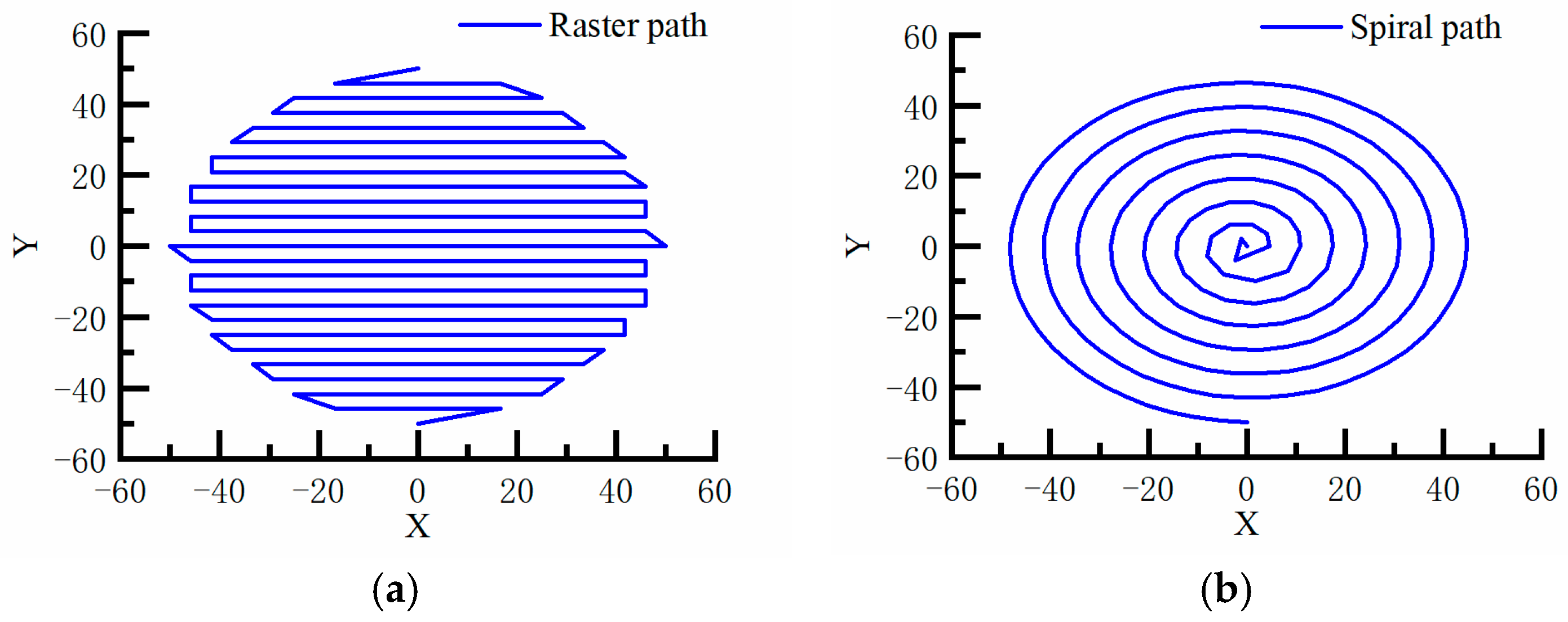
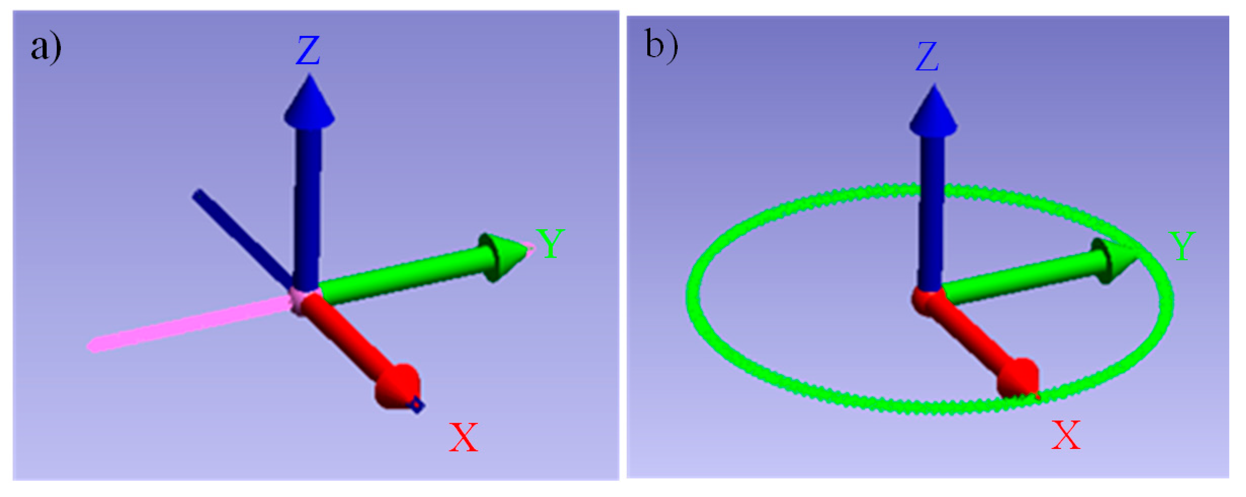
4.4. Surface Figuring Path Based on the SIAI Robot Motion Accuracy

After determining the figuring regions and the workpiece frame, the dual-robot fabrication system can be employed to figure the reflector based on the dwell time at each point along the surface figuring path. The positioning accuracy at each point is critical for machining the reflector surface using the system. This is due to the robot’s stiffness not being stable throughout the entire figuring path. Therefore, path planning is crucial, as the robot’s stiffness varies along the path, significantly affecting machining accuracy and efficiency [20,34].
To further improve surface figuring accuracy, the motion accuracy of the robot along different figuring paths was analyzed. The raster and spiral paths are two typical trajectories used in the surface figuring process, as illustrated in Figure 12. To investigate and simulate the influence of the path pattern on motion accuracy, the polishing tool was moved from −250 mm to 250 mm along the X and Y axes, respectively, as illustrated in Figure 13a. The tool was then moved along a circle with a radius of 250 mm on the X-Y plane, as illustrated in Figure 13b. The movements were measured using a laser tracker with the SMR mounted on the polishing tool, as illustrated in Figure 6a. The interval between the measured points was set to 3 mm.
The motion errors measured for the SIAI robot using different motion patterns are summarized in Table 2. From Table 2, it can be observed that the mean error and RMS error along the Y direction are 25.016 μm and 27.769 μm, respectively, which are lower than the mean and RMS errors of 54.472 μm and 63.408 μm along the X direction. The results indicate that the motion accuracy along the Y direction is superior to that along the X direction. For the circular motion, the mean and RMS errors are 144.746 μm and 160.801 μm, respectively. These errors are larger than those in both linear directions, which can be attributed to the fact that the circular motion results from a combination of movements along both the X and Y directions. The combined error C e can be easily calculated using the formula
C e = x e r r o r 2 + y e r r o r 2
The computed combined mean error C m e a n e r r o r and RMS error C m e a n e r r o r   for the circular motion are
C m e a n e r r o r = 54.47 2 m e a n e r r o r 2 + 25.01 6 m e a n e r r o r 2 = 59.9416   μ m ,
and
C R M S e r r o r = 63.40 8 R M S e r r o r 2 + 27.76 9 R M S e r r o r 2 = 69.222   μ m ,
both of which are smaller than the measured errors along the circular direction. This indicates that the errors are not merely the sum of the errors in each direction. One possible reason is that, when moving along a circular path, the difference in velocity gains along the X and Y directions is magnified, thereby amplifying the contour error in circle generation [38].
Based on the results, it is preferable to adopt a path where the robot moves along the X and Y directions without involving circular motions. Therefore, a classical meander raster-scanning tool path, as shown in Figure 12a, was adopted to model the reflector surface and achieve the required accuracy.
The primary objective of this section is to perform an analysis of the robot’s multi-position processing space, utilizing the robot kinematic model developed in the previous section and incorporating the dimensions of the CFRP reflector surface to be processed. Furthermore, a dual-robot, multi-position manufacturing layout has been implemented. Based on this, a high-precision support system was designed and fabricated to meet the stringent accuracy requirements for large-diameter antennas, ensuring that the reflector surface deformation does not exceed 5 μm. Additionally, a comparison between model predictions and experimental measurements was conducted to evaluate the operational accuracy of both the raster and spiral paths. The analysis reveals that the raster path demonstrates superior operational accuracy. Consequently, the raster path was selected for the processing of the CFRP antenna reflector surface.

5. Processing Experiments and Tool for Figuring the CFRP Antenna Reflector

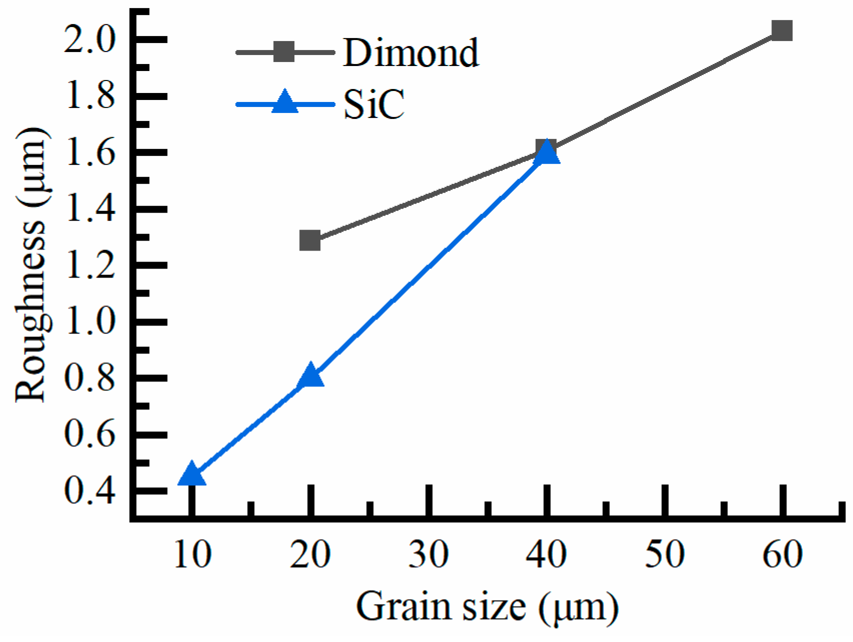
5.1. Processing Experiments to Obtain the Requested Surface Roughness for the CFRP Reflector

The properties of CFRP make it a highly promising material for applications in the aerospace and automotive industries. However, these properties also render CFRP components prone to defects during machining [39]. This is particularly evident when the rigidity of CFRP is comparable to that of fused silica, which has an elastic modulus of 91 GPa in the X and Y directions. However, in the Z direction, which is normal to the reflector surface, CFRP is significantly more flexible, with an elastic modulus of only 11.96 GPa. These mechanical characteristics of CFRP give rise to unique processing behaviors in terms of surface roughness.
To achieve the required surface roughness, ranging from 400 nm to 500 nm, lapping with a plate was employed to process the reflector surface, and processing experiments were carried out. Surface roughness experiments were performed using two types of loose abrasives (diamond and SiC) on the CFRP sample. The processing parameters for the experiments were identical, except for the grain size. The Taylor Hobson PGI 1240 (Taylor Hobson Ltd., Leicester, UK) was used to measure the CFRP surface roughness for each abrasive. The roughness results are presented in Figure 14. As shown in Figure 14, the roughness of the abrasives exhibits a linear relationship with the grain size for both abrasives. Furthermore, based on the roughness evolution trend of the diamond curve, a grain size of 10 μm for diamond would result in a roughness much larger than the desired surface roughness for the reflector. In contrast, the surface roughness processed by SiC with a grain size of 10 μm was approximately 450 nm, which satisfied the required specification. Therefore, SiC with a grain size of 10 μm was employed for processing the CFRP antenna reflector.

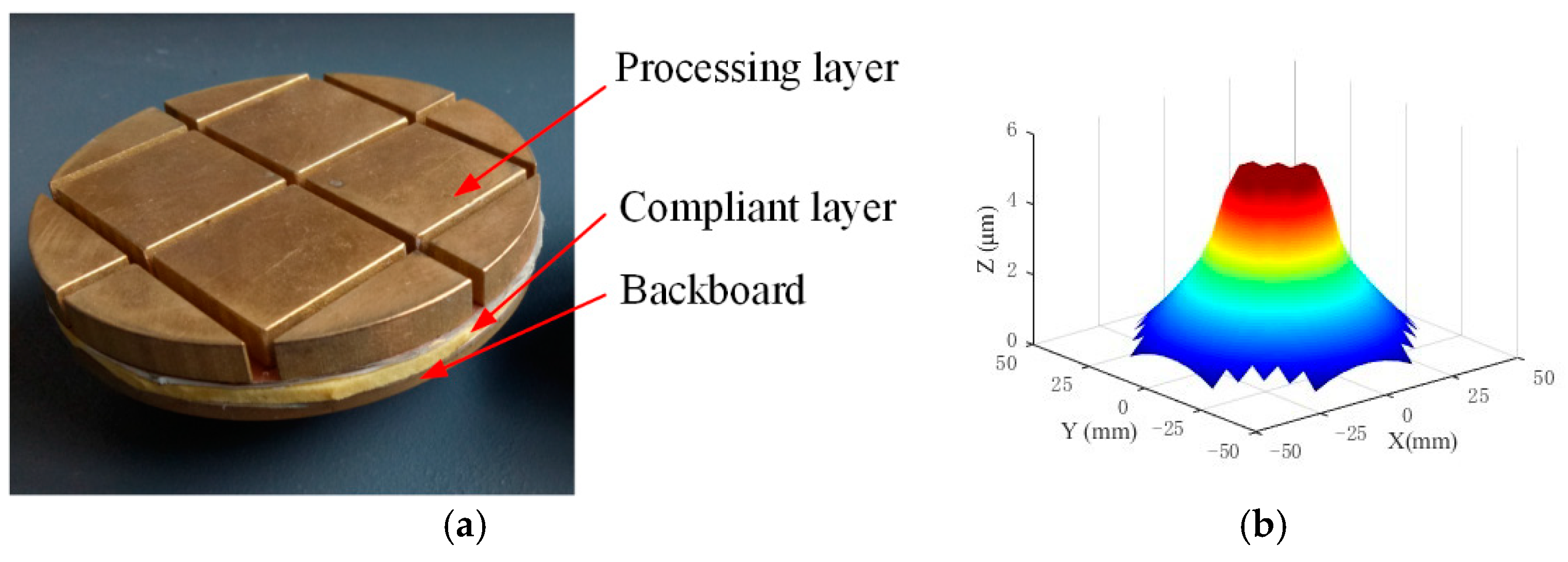
5.2. Tool for Figuring the Reflector Surface

The surface of the CFRP antenna reflector is relatively soft compared to traditional optical materials along its Z direction, as previously mentioned. To ensure that the processing tool conformed to the reflector surface, a flexible tool was employed for surface figuring. The processing tool consists of a backboard, a compliant layer, and a processing layer. With this structure, the tool could quickly adapt to the rapid changes in surface curvature, in contrast to a traditional rigid tool, as shown in Figure 15a,b. Figure 16a presents an image of the tool used for figuring the reflector surface. The tool moved in both a spinning and orbital motion, similarly to the traditional method used in computer-controlled optical surfacing [40]. The material removal was predicted by the widely accepted Preston equation [41]:
d z ( x , y ) = k P ( x , y ) V ( x , y ) d t
during the time interval d t . Here, d t represents the Preston constant, P is the pressure on the tool–component contact region, and V is the magnitude of the relative speed between the tool and component. Figure 16b illustrates the unit material removal predicted by the Preston equation for the tool. This material removal is used in figuring the reflector surface.
To reduce the traces produced between adjacent machining regions, the overlap of the lapping tool at the boundaries of these regions is deliberately considered when planning the surface figuring path. Figure 17 depicts the developed dual-robot fabrication system used for figuring the reflector surface.
A comparison of diamond and silicon carbide abrasives for machining silicon carbide materials was conducted. The results show that silicon carbide abrasives with a particle size of 10 μm effectively achieve a surface roughness of 450 nm on CFRP, meeting the technical requirements for roughness within the range of 400 nm to 500 nm. Additionally, incorporating a flexible layer on the grinding disc successfully addressed the issue of inaccurate material removal caused by the imperfect contact of the rigid disc, thereby enabling the development of precise figuring and localized roughness processing techniques for CFRP materials.

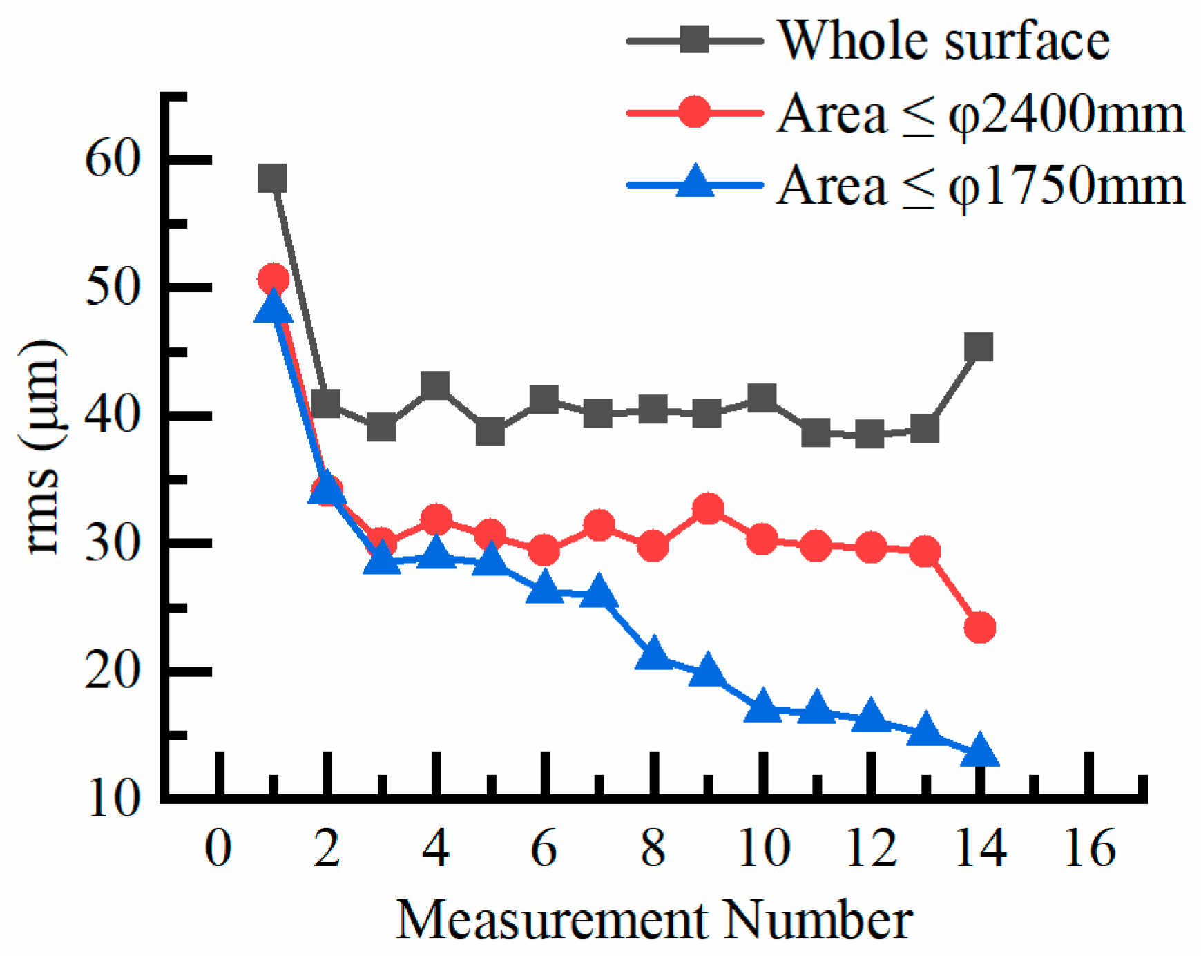
6. Results and Discussion for Figuring CFRP Reflector Surface by Using the Developed System

The figuring of a 2400 mm × 4580 mm CFRP antenna reflector was conducted using the previously constructed dual-robot multi-station machining platform, which incorporates a high-precision 18-point support structure and employs optimized figuring paths and processing methods. The surface figure accuracy requirements for the central areas (≤φ1750 mm and ≤φ2400 mm) were stricter than those for the remaining surface areas. Consequently, the central areas were isolated and processed multiple times to meet the required accuracy. Surface figure accuracy was measured using a Radian laser tracker. Prior to the figuring process, the surface figure accuracies for areas ≤ φ1750 mm, ≤φ2400 mm, and the entire surface were recorded as 42.3 μm rms, 51.7 μm rms, and 56.9 μm rms, respectively. The surface accuracy of the entire surface already satisfied the required specifications. Our strategy for figuring the reflector involved initially processing the entire surface to achieve the desired surface roughness. Subsequently, particular attention was given to processing the area ≤φ1750 mm to reach the desired accuracy while simultaneously managing the surface figure accuracy of the area ≤ φ2400 mm to maintain proximity to its target value. Once the surface figure accuracy of ≤φ1750 mm approached its target, both areas ≤ φ1750 mm and ≤φ2400 mm were processed simultaneously to meet their respective accuracy targets. The final surface, after machining, was measured three times, with the results presented in Table 3. The second and third measurements were performed 24 h after the initial measurement. As shown in Table 3, all results met the required accuracies. To ensure the accuracy targets were genuinely achieved, the worst results for each area were considered and are presented in Figure 18, which illustrates the RMS accuracy convergences for different regions of the reflector under the adopted figuring strategy. The final accuracies for areas ≤ φ1750 mm, ≤φ2400 mm, and the entire surface were improved to 13.7 μm rms, 24.2 μm rms, and 45.8 μm rms, respectively.
Figure 19 illustrates the surface form accuracies before and after fabrication. As the surface form accuracy in the area ≤φ1750 mm was higher, additional material was removed to achieve the required accuracy. As a result, the boundary between areas ≤ φ1750 mm and ≤φ2400 mm is visible in the final result, as shown in Figure 19b. To eliminate this issue, an effective approach is to first process the central area to achieve its surface figure accuracy, followed by processing the remaining surface with a comparable material removal rate. A significant drawback of this method is that it requires considerably more time to remove material from the entire surface of the reflector.

7. Conclusions

This paper systematically presents the development of a dual-robot fabrication system designed to meet the requirements for figuring a 2.4 m × 4.58 m CFRP antenna reflector surface and investigates its figuring properties. Methods and procedures are proposed for determining the tool center point (TCP) and tool calibration factor (TCF) for the in-house developed SIAI robot. The method integrates laser tracker measurement and numerical computation, enabling the rapid determination of the TCP with only a single posture, provided that the reference point coordinates are known in the robot’s base frame. The numerical computation of the workspace for the robot in each position is crucial for determining machining positions and regions for each robot, as well as for the development of the dual-robot fabrication system. The determination of machining positions also considers robot stiffness, ensuring that the robot does not operate beyond its limitations. Additionally, the support structure plays a critical role in achieving the required figure accuracy with the developed system. The motion trajectory of the figuring path significantly influences the robot’s motion accuracy. An optimized machining path can improve motion accuracy to some extent. Rectilinear motion offers higher accuracy than circular motion. The raster scanning path was selected for figuring the reflector surface to achieve the required surface figure accuracy. The results obtained provide a foundation for determining the optimal path to achieve higher figuring accuracy with the dual-robot fabrication system. The final surface accuracy achieved demonstrates the feasibility of the developed dual-robot fabrication system for figuring large-scale monolithic components. This research not only provides a reference for further improving surface figuring accuracy but also contributes to the development of robot fabrication systems for the precision manufacturing of even larger components. In the future, it will be essential to further develop a multi-parameter robotic motion and dynamics model that accounts for the influence of nonlinear factors and other variables, simulates their impact on motion accuracy, and investigates error compensation methods to enhance robotic simulation accuracy and improve motion precision.

Author Contributions

Conceptualization, Q.X., H.L. and Y.W.; Formal analysis, Q.X., H.L., J.W., L.L., X.H. and Z.Z.; Funding acquisition, Y.W.; Investigation, Q.X. and J.W.; Methodology, Q.X., H.L., X.H. and Z.Z.; Project administration, Y.W.; Resources, X.H.; Writing—original draft, Q.X.; Writing—review and editing, Z.Z. All authors have read and agreed to the published version of the manuscript.

Funding

This research received no external funding.

Data Availability Statement

The original contributions presented in this study are included in the article. Further inquiries can be directed to the corresponding author.

Conflicts of Interest

Author Xufeng Hao was employed by the company Shanghai Composites Science & Technology Co., Ltd. The remaining authors declare that the research was conducted in the absence of any commercial or financial relationships that could be construed as a potential conflict of interest.

References

  1. Bernstein, R.A.; McCarthy, P.J.; Raybould, K.; Bigelow, B.C.; Bouchez, A.H.; Filgueira, J.M.; Jacoby, G.; Johns, M.; Sawyer, D.; Shectman, S.; et al. Overview and status of the Giant Magellan Telescope project. In Proceedings of the Ground-Based and Airborne Telescopes V, Montreal, QC, Canada, 22–27 June 2014; Volume 9145, pp. 494–509. [Google Scholar]
  2. Graves, L.R.; Smith, G.A.; Apai, D.; Kim, D.W. Precision Optics Manufacturing and Control for Next-Generation Large Telescopes. Nanomanufacturing Metrol. 2019, 2, 65–90. [Google Scholar]
  3. Martin, H.M.; Burge, J.H.; Davis, J.M.; Kim, D.W.; Kingsley, J.S.; Law, K.; Loeff, A.; Lutz, R.D.; Merrill, C.; Strittmatter, P.A.; et al. Status of mirror segment production for the Giant Magellan Telescope. In Proceedings of the Advances in Optical and Mechanical Technologies for Telescopes and Instrumentation II, Edinburgh, UK, 26 June–1 July 2016; Volume 9912, pp. 266–277. [Google Scholar]
  4. Cayrel, M. E-ELT optomechanics: Overview. In Proceedings of the SPIE—The International Society for Optical Engineering, Amsterdam, The Netherlands, 1–6July 2012; Volume 8444, pp. 674–691. [Google Scholar]
  5. Rajan, R.T.; Boonstra, A.-J.; Bentum, M.; Klein-Wolt, M.; Belien, F.; Arts, M.; Saks, N.; van der Veen, A.-J. Space-based aperture array for ultra-long wavelength radio astronomy. Exp. Astron. 2016, 41, 271–306. [Google Scholar]
  6. National Academy of Engineering. Frontiers of Engineering: Reports on Leading-Edge Engineering from the 2015 Symposium; The National Academies Press: Washington, DC, USA, 2016. [Google Scholar]
  7. Hegde, S.; Satish Shenoy, B.; Chethan, K.N. Review on carbon fiber reinforced polymer (CFRP) and their mechanical performance. Mater. Today Proc. 2019, 19, 658–662. [Google Scholar]
  8. Zhang, J.; Lin, G.; Vaidya, U.; Wang, H. Past, present and future prospective of global carbon fibre composite developments and applications. Compos. Part B Eng. 2023, 250, 110463. [Google Scholar]
  9. Wu, W.; Li, S.; Qin, X.; Fu, G.; Bao, Z.; Li, H.; Zhao, Q. Tool wear influence on surface roughness, burrs and cracks in milling unidirectional carbon fiber reinforced plastics (UD-CFRP). J. Mater. Res. Technol. 2024, 30, 3052–3065. [Google Scholar]
  10. Li, J.; Kang, R.; Tian, J.; Dong, Z.; Yan, B. The influence of precision polishing parameters on surface roughness of resin-rich layer on antenna reflective surface. Diam. Abras. Eng. 2023, 43, 250. [Google Scholar]
  11. Qian, Y.; Kan, F.W.; Sarawit, A.T.; Lou, Z.; Cheng, J.-Q.; Wang, H.-R.; Zuo, Y.-X.; Yang, J. Conceptual Design of the Aluminum Reflector Antenna for DATE5. Res. Astron. Astrophys. 2016, 16, 6. [Google Scholar]
  12. Qian, Y.; Lou, Z.; Hao, X.; Zhu, J.; Cheng, J.; Wang, H.; Zuo, Y.; Yang, J. Initial development of high-accuracy CFRP panel for DATE5 antenna. Adv. Opt. Mech. Technol. Telesc. Instrum. II 2016, 9912, 475–482. [Google Scholar]
  13. Qian, Y.; Hao, X.; Shi, Y.; Cai, D.a.; Wu, N.; Lou, Z.; Zuo, Y. Deformation behavior of high accuracy carbon fiber-reinforced plastics sandwiched panels at low temperature, Journal of Astronomical Telescopes. Instrum. Syst. 2019, 5, 034003. [Google Scholar]
  14. Perez, R.; Gutierrez, S.C.; Zotovic, R. A study on robot arm machining: Advance and future challenges. In Proceedings of the 29th International DAAAM Symposium, Zadar, Croatia, 24–27 October 2018; Volume 29, pp. 931–940. [Google Scholar]
  15. Torres, R.; Mata, S.; Iriarte, X.; Barrenetxea, D. Robotic Belt Finishing with Process Control for Accurate Surfaces. J. Manuf. Mater. Process. 2023, 7, 124. [Google Scholar] [CrossRef]
  16. Pedroso, A.F.V.; Sebbe, N.P.V.; Silva, F.J.G.; Campilho, R.D.S.G.; Sales-Contini, R.C.M.; Costa, R.D.F.S.; Sánchez, I.I. An overview on the recent advances in robot-assisted compensation methods used in machining lightweight materials. Robot. Comput.-Integr. Manuf. 2025, 91, 102844. [Google Scholar] [CrossRef]
  17. Caro, S.; Dumas, C.; Garnier, S.; Furet, B. Workpiece placement optimization for machining operations with a KUKA KR270-2 robot. In Proceedings of the 2013 IEEE International Conference on Robotics and Automation, Karlsruhe, Germany, 6–10 May 2013; pp. 2921–2926. [Google Scholar]
  18. Iglesias, I.; Sebastián, M.A.; Ares, J.E. Overview of the State of Robotic Machining: Current Situation and Future Potential. Procedia Eng. 2015, 132, 911–917. [Google Scholar] [CrossRef]
  19. Barosz, P.; Gołda, G.; Kampa, A. Efficiency Analysis of Manufacturing Line with Industrial Robots and Human Operators. Appl. Sci. 2020, 10, 2862. [Google Scholar] [CrossRef]
  20. Ji, W.; Wang, L. Industrial Robotic Machining: A Review. Int. J. Adv. Manuf. Technol. 2019, 103, 1239–1255. [Google Scholar]
  21. Chen, H.; Yaseer, A.; Zhang, Y. Top Surface Roughness Modeling for Robotic Wire Arc Additive Manufacturing. J. Manuf. Mater. Process. 2022, 6, 39. [Google Scholar] [CrossRef]
  22. Walker, D.; Wang, W.; Xu, M.; Yu, G. Coordinate transformation of an industrial robot and its application in deterministic optical polishing. Opt. Eng. 2014, 53, 055102. [Google Scholar]
  23. Xin, Q.; Liu, H.; Wu, J.; Tang, L.; Wang, D.; Wan, Y. Surface Figuring of Large Carbon Fiber Reinforced Polymer Antenna Reflector with A Dual-robots Fabrication System. EPJ Web Conf. 2019, 215, 05005. [Google Scholar]
  24. Li, H.; Walker, D.; Zheng, X.; Yu, G.; Reynolds, C.; Zhang, W.; Li, T. Advanced techniques for robotic polishing of aluminum mirrors. In Proceedings of the SPIE Optical Systems Design, Frankfurt, Germany, 14–17 May 2018; Volume 10692, pp. 152–163. [Google Scholar]
  25. Yao, Y.; Ma, Z.; Ding, J.; Chen, Q.; Fan, X.; Shen, L.; Li, Q. Heavy-calibre off-axis aspheric surface polishing by industrial robot. In Proceedings of the 9th International Symposium on Advanced Optical Manufacturing and Testing Technologies: Meta-Surface-Wave and Planar Optics, Chengdu, China, 26–29 June 2018; Volume 10838, pp. 16–24. [Google Scholar]
  26. Wan, S.; Zhang, X.; Xu, M.; Wang, W.; Jiang, X. Region-adaptive path planning for precision optical polishing with industrial robots. Opt. Express 2018, 26, 23782–23795. [Google Scholar]
  27. Hasirden; Zeng, Z.; Liu, H.; Zhao, H. Measurement and analyses on positioning accuracy for optical processing robots. Opto-Electron. Eng. 2017, 44, 516–522. [Google Scholar]
  28. Liu, H.; Wan, Y.; Zeng, Z.; Xu, L.; Zhao, H.; Fang, K. Freeform surface grinding and polishing by CCOS based on industrial robot. In Proceedings of the Eighth International Symposium on Advanced Optical Manufacturing and Testing Technology (AOMATT2016), Suzhou, China, 26–29 April 2016; Volume 9683, pp. 587–593. [Google Scholar]
  29. Brooks, D.R.; Brunelle, M.; Lynch, T.; Medicus, K. Manufacturing of a large, extreme freeform, conformal window with robotic polishing. In Proceedings of the SPIE Optical Engineering + Applications, San Diego, CA, USA, 19–23 August 2018; Volume 10742, pp. 126–133. [Google Scholar]
  30. Zhao, Q.; Zhang, K.; Zhu, S.; Xu, H.; Cao, D.; Zhao, L.; Zhang, R.; Yin, W. Review on the Electrical Resistance/Conductivity of Carbon Fiber Reinforced Polymer. Appl. Sci. 2019, 9, 2390. [Google Scholar] [CrossRef]
  31. Zhou, X.; Zhou, X.; Du, D.; Kong, X.; Qin, G. Low Deformation Optimized Design of CFRP Antenna Reflector. Spacecr. Eng. 2018, 27, 83–88. [Google Scholar]
  32. Utsunomiya, S.; Kamiya, T.; Shimizu, R. Development of CFRP mirrors for space telescopes. In Proceedings of the SPIE Astronomical Telescopes + Instrumentation, San Diego, CA, USA, 25–29 August 2013; Volume 8837, pp. 206–211. [Google Scholar]
  33. Craig, J.J. Introduction to Robotics: Mechanics and Control, 3rd ed.; Pearson Education: Upper Saddle River, NJ, USA, 2014. [Google Scholar]
  34. Chen, Y.; Dong, F. Robot machining: Recent development and future research issues. Int. J. Adv. Manuf. Technol. 2013, 66, 1489–1497. [Google Scholar]
  35. Park, K.-S.; Lee, J.H.; Youn, S.-K. Lightweight mirror design method using topology optimization. Opt. Eng. 2005, 44, 053002. [Google Scholar]
  36. Wang, H.; Lou, Z.; Qian, Y.; Zheng, X.; Zuo, Y. Hybrid optimization methodology of variable densities mesh model for the axial supporting design of wide-field survey telescope. Opt. Eng. 2016, 55, 035105. [Google Scholar] [CrossRef]
  37. Luo, X.; Qi, E.; Hu, H.; Hu, H.; Ford, V.G.; Cole, G. Fabrication and metrology study for M3MP of TMT. In Proceedings of the Eighth International Symposium on Advanced Optical Manufacturing and Testing Technology (AOMATT2016), Suzhou, China, 26–29 April 2016; Volume 9682, pp. 49–57. [Google Scholar]
  38. Vázquez, E.; Gomar, J.; Ciurana, J.; Rodríguez, C.A. Evaluation of machine-tool motion accuracy using a CNC machining center in micro-milling processes. Int. J. Adv. Manuf. Technol. 2015, 76, 219–228. [Google Scholar]
  39. Chen, T.; Gao, F.; Li, S.; Liu, X. The Comparative Study on Cutting Performance of Different-Structure Milling Cutters in Machining CFRP. Appl. Sci. 2018, 8, 1353. [Google Scholar] [CrossRef]
  40. Nam, H.-S.; Kim, G.-C.; Kim, H.-S.; Rhee, H.-G.; Ghim, Y.-S. Modeling of edge tool influence functions for computer controlled optical surfacing process. Int. J. Adv. Manuf. Technol. 2016, 83, 911–917. [Google Scholar] [CrossRef]
  41. Haitao, L.; Zhige, Z.; Fan, W.; Bin, F.; Yongjian, W. Study on active lap tool influence function in grinding 1.8 m primary mirror. Appl. Opt. 2013, 52, 7504–7511. [Google Scholar]
Figure 1. Structure for developing a dual-robot fabrication system to figure a large antenna reflector.
Machines 13 00268 g001
Figure 2. Dimensions of the CFRP antenna reflector.
Machines 13 00268 g002
Figure 3. Large and middle-scale optical fabrication systems based on (a) SIAI robot and (b) Stäubli robots.
Machines 13 00268 g003
Figure 4. The in-house developed 6-axis SIAI robot.
Machines 13 00268 g004
Figure 5. Position errors between the recorded data and the theoretical computations.
Machines 13 00268 g005
Figure 6. (a) SMR mounted on the base and (b) the polishing tool.
Machines 13 00268 g006
Figure 7. Coordinate transformation between rotation angle and Z-axis.
Machines 13 00268 g007
Figure 8. Horizontal workspace of the SIAI robot (a) before and (b) after adjusting the robot position.
Machines 13 00268 g008
Figure 9. Computed workspaces for a SIAI robot with (a) two and (b) three machining positions.
Machines 13 00268 g009
Figure 10. (a) Schematic of the dual-robot fabrication system and (b) machining regions for each robot.
Machines 13 00268 g010
Figure 11. (a) The Whiffletree support system and (b) the corresponding support forces.
Machines 13 00268 g011
Figure 12. Schematic diagram of the commonly used trajectories, (a) raster path and (b) spiral path.
Machines 13 00268 g012
Figure 13. Motion trajectories for the polishing tool end moving along (a) lines and (b) circle.
Machines 13 00268 g013
Figure 14. Relationships between abrasives and the surface roughness.
Machines 13 00268 g014
Figure 15. The flexible processing tools (a) with and (b) without compliant layer.
Machines 13 00268 g015
Figure 16. (a) Flexible processing tool used in figuring the reflector surface and (b) corresponding unit material removal.
Machines 13 00268 g016
Figure 17. Image of the CFRP antenna reflector and the dual-robot fabrication system.
Machines 13 00268 g017
Figure 18. Accuracy convergences for different regions of the reflector.
Machines 13 00268 g018
Figure 19. Surface figure (a) before and (b) after being processed by the dual-robot fabrication system.
Machines 13 00268 g019
Table 1. The DH link parameters of the SIAI robot.
Link   i a i 1   ( m m ) d i   ( m m ) α i 1   ( ° ) θ i   ( ° ) Range of Motion
1010210 θ 1 −145°~145°
20 d 2 00−5 mm~904 mm
31402.08−2290 θ 3 + 90 −156°~156°
401400.790 θ 4 −183°~183°
500−90 θ 5 −120~120°
6034490 θ 6 −195°~195°
700−90−900
Table 2. Motion accuracy of SIAI robot under different interpolation methods.
ErrorMotion Along X
Direction (μm)
Motion Along Y
Direction (μm)
Circular Motion (μm)
Mean54.47225.016144.746
rms63.40827.769160.801
Maximum138.12557.276324.909
Minimum5.9471.82210.158
Table 3. Surface figure accuracies for different regions of the reflector.
Measurement No.rms Accuracy (μm)
≤φ1750 mm≤φ2400 mmWhole Surface
1st13.423.445.8
2nd 13.52442.8
3rd13.724.241.5
Disclaimer/Publisher’s Note: The statements, opinions and data contained in all publications are solely those of the individual author(s) and contributor(s) and not of MDPI and/or the editor(s). MDPI and/or the editor(s) disclaim responsibility for any injury to people or property resulting from any ideas, methods, instructions or products referred to in the content.

