Article

Meshing Performance Analysis of a Topologically Modified and Formed Internal Helical Gear Pair

1
School of Mechatronics Engineering, Henan University of Science and Technology, Luoyang 471003, China
2
Longmen Laboratory, Luoyang 471000, China
3
Zhengzhou Institute of Machinery (Zhengzhou) Transmission Technology Co., Ltd., Zhengzhou 450066, China
*
Author to whom correspondence should be addressed.
Machines 2025, 13(5), 340; https://doi.org/10.3390/machines13050340
Submission received: 7 March 2025 / Revised: 6 April 2025 / Accepted: 19 April 2025 / Published: 22 April 2025
(This article belongs to the Section Machine Design and Theory)

Abstract

:
Internal helical gear pairs are sensitive to manufacturing and assembly errors, loading deformation, which can result in vibration and noise. Three-dimensional topological modification of tooth surfaces is available to reduce this sensitivity. A 3D topological modification method is proposed by means of an internal helical gear form grinding method. The modified tooth surface model was constructed using spatial meshing theory and matrix transformations. Loaded tooth contact analysis (LTCA) was established to investigate the effect law of modification parameters on gear loading performance. Simulation results indicated that the contact area appeared at the middle area of the tooth surface under design loading conditions, with little edge contact existing. Transmission error decreased by up to 28.4% compared to the tooth without modification. The dynamic meshing performance of the internal helical gear pair was enhanced significantly. A transmission experiment was conducted to verify the effectiveness and validity of the simulation results.

1. Introduction

Internal helical gears are widely applied in various industrial fields such as aerospace, automobile, and ship industries due to their advantages of compact structure, high load capacity, long service life, large transmission ratio, and low noise [1,2,3]. Internal helical gears are sensitive to manufacturing and installation errors, as well as load-induced deformation. This leads to abrupt changes and poor uniformity in contact stress on the tooth surface, particularly during meshing engagement and disengagement, which in turn causes vibration and noise in the transmission system [3,4,5].
Tooth surface topological modification techniques, specifically a three-dimensional tooth profile and longitudinal modification, effectively reduce vibration and noise in gear transmissions [6]. Zhao proposed a method of grinding tooth surface modification based on gear geometric parameters and tooth surface topological modification expression. This method utilized second-order and fourth-order curves to establish the mathematical relationship between gear geometric parameters and tooth topology modification parameters [7]. Chen et al. established a nonlinear meshing model considering tooth deviation. They combined tooth modification with a dynamic model, compensated for error based on the composite modification, and calculated the vibration suppression effect of convex tooth modification [8]. Jiang et al. proposed a design method for high order transmission error curves. This method determined modification parameters by optimizing the minimum error amplitude of loading transmission and calculated the normal modification surface of the pinion through inversion of rack motion parameters [9]. Yang et al. proposed a gear design method based on high-order parabolic modification. They verified the insensitivity of the four-order modification designs to installation errors by constructing a mathematical model [10]. Yan et al. proposed a three-dimensional distributed dynamic drum shape modification method. This method described the modification curve using a polynomial function [11]. Wu et al. applied static and dynamic contact finite element analysis to achieve precise helical gear tooth modification and optimize both the modification amount and form [12]. Zhang et al. analyzed the axial angle error of installed helical gears and reduced the loading transmission error fluctuation by implementing higher-order asymmetric modification using circular tools [13].
Loaded tooth contact analysis (LTCA) of gear systems, performed through simulation software, accurately calculates stress distribution and deformation in the gear contact area. This approach reduces experimental cost and optimize tooth modification parameters, thereby enhancing gear meshing performance based on the analysis results. Jia et al. proposed a tooth profile modification method hat considered the gear contact ratio. This method was based on gear tooth contact analysis and loaded gear tooth contact analysis. They developed a new approach to calculate the meshing impact forces and optimize tooth topology modification, aiming to minimize loaded transmission error and meshing impact forces [14]. Wang et al. extracted the node and element information of the gears and applied it to finite element analysis software for automatic model construction. Their study revealed the effects of tooth modification on the transmission errors and contact stresses in both spur gears and helical gears [15]. Zhao et al. proposed an improved loaded tooth contact analysis model that considered various assembly errors and their coupling effects [16]. Bejar et al. employed different simulation software to simulate and compare gearbox performance. Their study revealed the influence of micro-geometric modification, gearbox system scale and other factors on complex stacking effects, and established criteria for specific analysis scenarios [17].
Although these scholars have made some achievements in tooth modification and meshing performance analysis, little research has been carried out on the modification method, mathematical modeling of mesh performance and computer-aided simulation of internal helical gears pair manufactured by form grinding. A three-dimensional topological modification method was proposed for the gears form grinding, a mathematical model of topological modification of internal helical gears was constructed, and a loaded tooth contact analysis model was established based on finite elements to study the influence of profile parameters on loaded tooth contact analysis, to optimize the contact area through modification parameters and decrease the sensitivity to installation errors. Tooth contact analysis was verified by computer simulation. Finally, the feasibility and correctness of the modification method were verified by experiments.

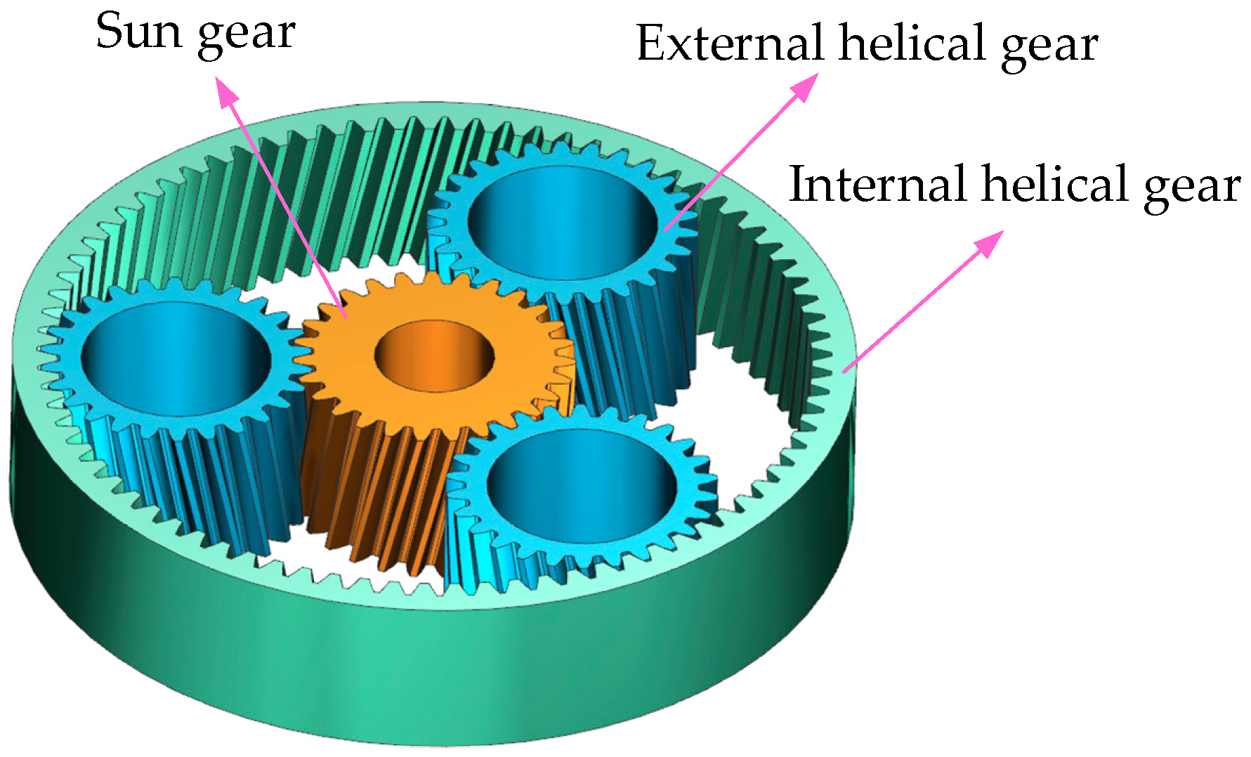
2. Mathematical Modeling of Internal Helical Gears Pair

The planetary helical gear train consists of internal and external meshing gear pairs, as illustrated in Figure 1, which features a compact structure, high power density and wide application [18]. However, due to its high assembly and manufacturing difficulty, the installation of multiple planetary gears requires ensuring uniform distribution and synchromesh, while the dynamic balance of both the planetary carrier and gears must be maintained during high-speed operation [19].The meshing accuracy among planetary gears, sun gears and internal gear rings directly affects the transmission performance. Each planetary gear simultaneously engages with both the sun gear and internal gear ring, bearing bidirectional loads that frequently lead to tooth surface stress concentration and wear. Additionally, the internal gear ring presents significant manufacturing challenges. Implementing tooth surface modification on planetary gears can simultaneously improve meshing performance with both sun gears and internal gear rings, reduce impact loads, and enhance transmission smoothness.

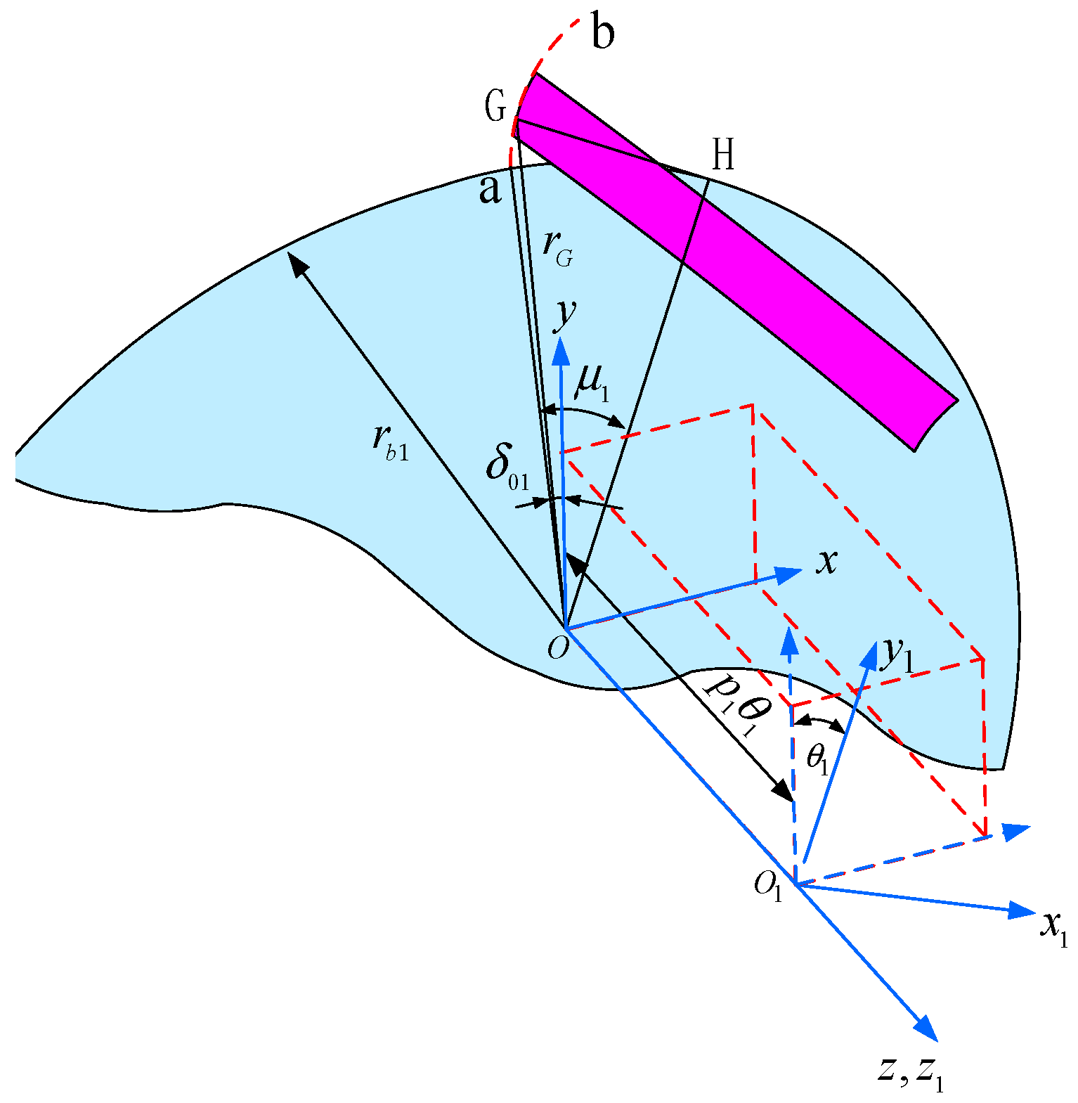
2.1. Internal Helical Gear Tooth Equation

The end section of the involute helical surface in internal helical gear forms an involute curve. The helical surface generated by the involute profile a b rotating around the Z axis through helical motion constitutes the tooth surface of the helical gear, as illustrated in Figure 2. The starting point of the right-side tooth space involute a b is point a , and for any point G ( x G , y G ) on the base circle, its corresponding tangent point is H; the base circle radius is denoted as r b 1 , the parameter variable is denoted as a O H = μ 1 , the base circle tooth space half-angle is denoted as δ 01 , and the equation of the involute is as follows:
r O 1 = r b 1 sin ( μ 1 δ 01 ) r b 1 μ 1 cos ( μ 1 δ 01 ) r b 1 cos ( μ 1 δ 01 ) + r b 1 μ 1 sin ( μ 1 δ 01 ) 0 1
The coordinate system S 1 is fixed to the workpiece, S O is fixed to the frame, z o and z 1 are coaxial and along the same direction. The helix parameter is denoted as p 1 , the turning angle parameter is denoted as θ 1 , and the axial travel distance is denoted as L . The end section involute curve in the S O moves helically around the axis of the workpiece z 1 and satisfies the following equation:
L = p 1 θ 1
The coordinate transformation matrix from S O to S 1 is expressed as follows:
M 1 O = cos θ 1 sin θ 1 0 0 sin θ 1 cos θ 1 0 0 0 0 1 p 1 θ 1 0 0 0 1
Then, the tooth surface vector equation of the internal helical gear is expressed as follows:
r 1 = M 1 O r O 1
r 1 ( 1 ) ( μ 1 , θ 1 ) = r b 1 sin ( μ 1 + θ 1 δ 01 ) r b 1 μ 1 sin ( μ 1 + θ 1 δ 01 ) ± r b 1 cos ( μ 1 + θ 1 δ 01 ) ± r b 1 μ 1 cos ( μ 1 + θ 1 δ 01 ) p 1 θ 1 1
The upper and lower symbols of “ ± ” in the equation are calculated in the right and left tooth surfaces, respectively.

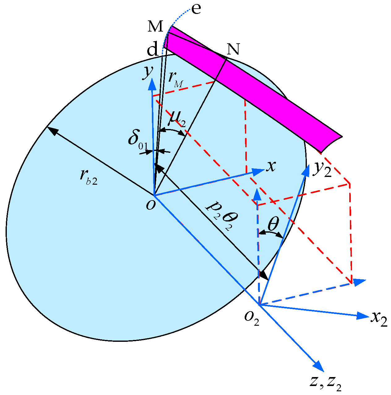
2.2. External Helical Gear Tooth Equations

Similar to internal helical gear, the end section of external helical cylindrical gear exhibits an involute profile, where the helical tooth surface forms through the helical motion of involute d e rotating around the Z axis. As illustrated in Figure 3, the starting point of the left-side tooth space involute d e is point d , and for any point M ( x M , y M ) on this base circle involute, its corresponding tangent point is N . In the coordinate system of S O , the base circle radius is denoted as r b 2 , the parametric variable is denoted as d O N = μ 2 , and the base circle tooth space half-angle is denoted as δ 02 . According to the property of the involute, the equation of the end surface is expressed as follows:
r O 2 = r b 2 sin ( μ 2 + δ 02 ) r b 2 μ 2 cos ( μ 2 + δ 02 ) r b 2 cos ( μ 2 + δ 02 ) + r b 2 μ 2 sin ( μ 2 + δ 02 ) 0 1
The coordinate system S 2 is fixed to the workpiece, S O is fixed to the frame, and z O and z 2 are coaxial and along the same direction. The involute of the end surface in the frame S O moves helically around the axis of the workpiece z 2 , the parametric variable is denoted as θ 2 , and the coordinate transformation matrix from S O to S 2 is expressed as follows:
M 2 O = cos θ 2 sin θ 2 0 0 sin θ 2 cos θ 2 0 0 0 0 1 p 2 θ 2 0 0 0 1
Then, the tooth vector equation of the external helical gear is expressed as follows:
r 2 = M 2 O r O 2
Substituting (6) and (7) into (8), the tooth vector equation of the external helical gear is obtained as follows:
r 2 ( 2 ) ( μ 2 , θ 2 ) = r b 2 sin ( μ 2 + δ 02 + θ 2 ) r b 2 μ 2 cos ( μ 2 + δ 02 + θ 2 ) ± r b 2 cos ( μ 2 + δ 02 + θ 2 ) ± r b 2 μ 2 sin ( μ 2 + δ 02 + θ 2 ) p 2 θ 2 1
The upper and lower symbols of “ ± ” in the equation are calculated in the left and right tooth surfaces, respectively.

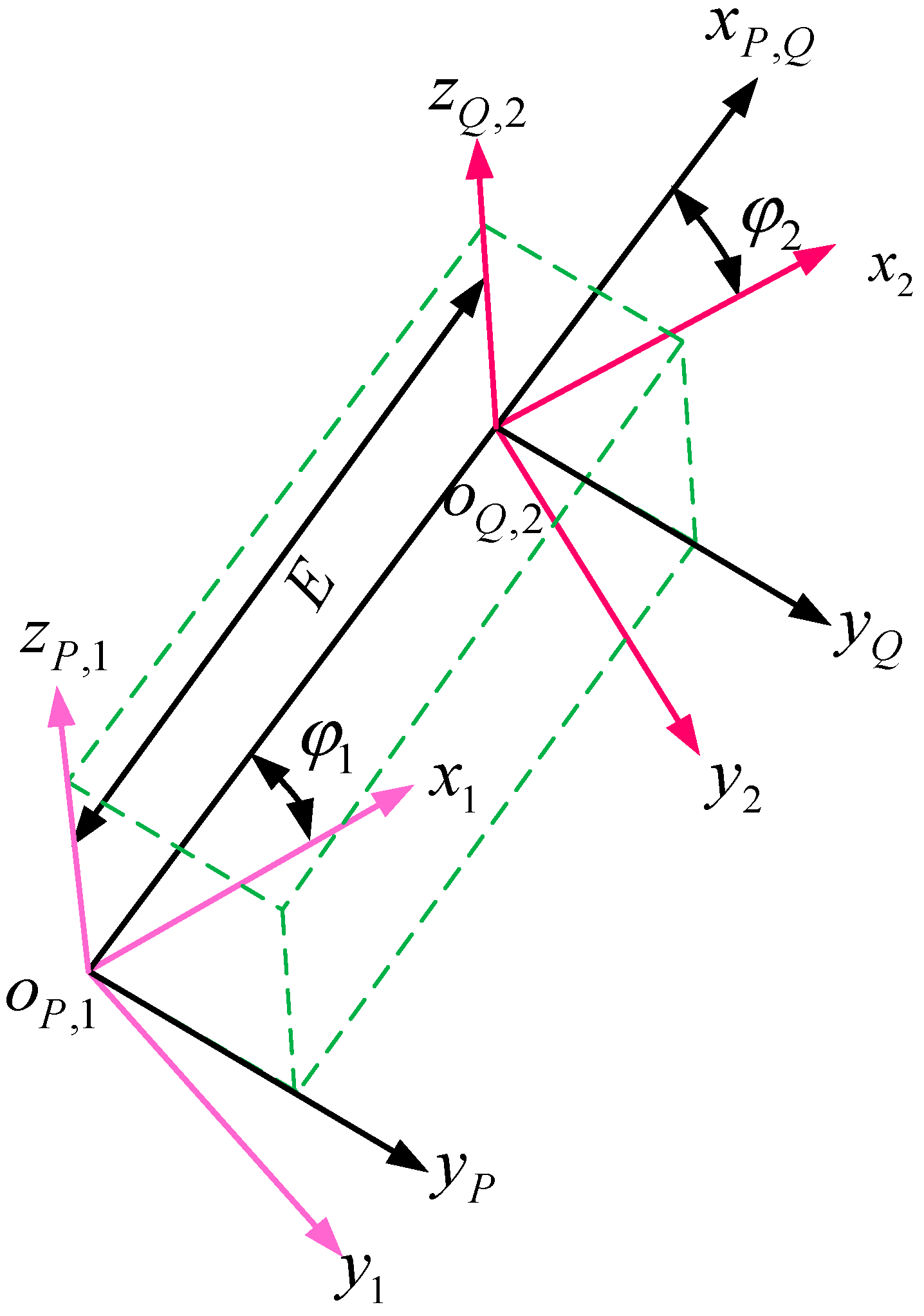
2.3. Internal Helical Gear Pair Meshing Coordinate System

The internal helical gear meshing coordinate system is illustrated in Figure 4. The coordinate system S P and S Q are rigidly fixed to the frame, and the coordinate axes are parallel and in the same direction. The installation axes z P and z Q correspond to the internal and external helical gears. The coordinate systems S 1 and S 2 are fixed to the internal helical gears and the external helical gears; z 1 and z 2 coincide with z P and z Q , respectively. The instantaneous rotational angles of the internal and external helical gears during meshing rotation are denoted as φ 1 and φ 2 , respectively.
The coordinate transformation matrix from the coordinate system S 1 to S P is expressed as follows:
M P 1 = cos φ 1 sin φ 1 0 0 sin φ 1 cos φ 1 0 0 0 0 1 0 0 0 0 1
The coordinate transformation matrix from the coordinate system S P to S Q is expressed as follows:
M Q P = 1 0 0 E 0 1 0 0 0 0 1 0 0 0 0 1
The coordinate transformation matrix from the coordinate system S Q to S 2 is expressed as follows:
M 2 Q = cos φ 2 sin φ 2 0 0 sin φ 2 cos φ 2 0 0 0 0 1 0 0 0 0 1
Thus, the coordinate transformation matrix from the coordinate system S 1 to S 2 is expressed as follows:
M 21 = M 2 P M P 1
Substituting (10)–(11) into (12), the coordinate transformation matrix from the coordinate system S 1 to S 2 is obtained as follows:
M 21 = cos ( φ 2 φ 1 ) sin ( φ 2 φ 1 ) 0 E cos φ 2 sin ( φ 2 φ 1 ) cos ( φ 2 φ 1 ) 0 E sin φ 2 0 0 1 0 0 0 0 1

3. Topological Modification of Internal Helical Gear

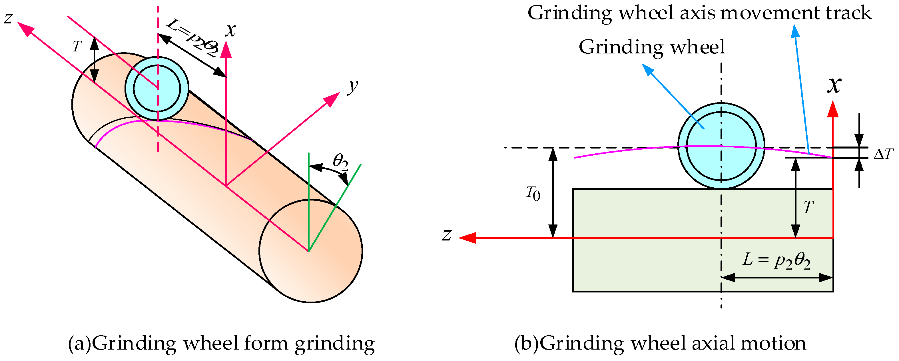
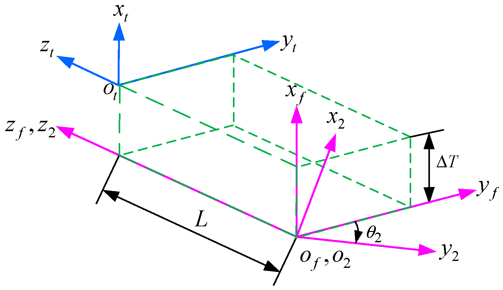
3.1. Modification of External Helical Gear

Gear modification methods include tooth profile modification, longitudinal modification, and topology modification. As illustrated in Figure 5, the contact line is a straight line inclined at the helix angle along both the tangent direction of the base cylinder and the axis. Therefore, for helical gear, tooth profile modification alone has a limited effect on improving adaptability to installation and manufacturing errors. As illustrated in Figure 6, Litvin et al. [20] proposed a three-dimensional topological modification method known as double-crowning modification, which integrates both profile and longitudinal modifications. This modification is implemented during gear hobbing by substituting the conventional straight-edged rack cutter blade with a three-segment parabolic curve to achieve profile modification, while lead modification is accomplished through adjustments to the generating motion.
In this paper, the principle of profile grinding is employed to implement comprehensive topological modification incorporating both profile and longitudinal modification, and tooth profile modification is realized by changing the profile of the grinding wheel, while longitudinal modification is obtained through changing the grinding motion trajectory. As illustrated in Figure 7, the modified helical gear tooth surface is divided into nine distinct regions. Region 0 represents the unmodified involute tooth surface; regions 1, 3, 6, and 8 incorporate both profile and longitudinal modification, regions 4 and 5 feature longitudinal modification, and regions 2 and 7 contain profile modification. Due to the internal helical gear with a large number of teeth being difficult to machine, topological modification is carried out only to the external helical gear, leaving the internal helical gear tooth surface unmodified.

3.2. Topologically Modified Tooth Equations

3.2.1. Tooth Equation of Profile-Modification External Helical Gear

Tooth profile modification is designed to remove material from the interfering portions of the tooth surface, thereby reducing the dynamic loads generated during gear meshing and mitigating or preventing tooth surface scoring damage. As illustrated in Figure 8a, the dotted line represents the theoretical involute, while the solid line shows the modified involute. The modified involute formed by adding a modification value Δ L to the theoretical involute, with no modification applied at point L 0 in the middle of the tooth width. The mathematical relationship between the modification value and the length of the generating line of the involute follows either a parabolic or higher-order curved function, as shown in Figure 8b.
a c is the tooth profile modification parameter. The modification quantity Δ L is expressed as a second-order parabolic modified curve function:
Δ L = a c ( r b u 2 r b u 2 ( 0 ) ) 2
σ 2 is half angle of the base circular tooth space of the external helical gear. The profile vector of the tooth end section of the modified helical gear is expressed as follows:
r 20 = r b 2 cos ( σ 2 + u 2 ) + ( r b 2 u 2 + Δ L ) sin ( σ 2 + u 2 ) r b 2 sin ( σ 2 + u 2 ) ( r b 2 u 2 + Δ L ) cos ( σ 2 + u 2 ) 0 1

3.2.2. Tooth Equations of Ground and Modified External Helical Gear

As illustrated in Figure 9a, the grinding motion of modified helical gear is achieved by rotating the grinding wheel axis according to the workpiece helix angle, where the grinding wheel moves along the gear longitudinal direction while the workpiece rotates about its own axis, with both motions precisely coordinated according to the workpiece helix parameters. Longitudinal tooth modification is accomplished through controlled relative motion between the grinding wheel and workpiece, incorporating additional radial movement Δ T of the grinding wheel toward the workpiece axis center during standard longitudinal grinding operations, as demonstrated in Figure 9b.
According to the grinding trajectory for longitudinal modification, where a p represents the parabolic coefficient, p 2 represents the helix coefficient, θ 2 represents the turning angle parameter, and B represents the tooth width, the longitudinal modification function is expressed as follows:
Δ T = a p ( p 2 θ 2 B 2 ) 2
The grinding coordinate system of modified external helical gears is illustrated in Figure 10. The coordinate system S f and the coordinate system S 2 are fixed to the mounting frame of the gear rotary table and the workpiece assembly, respectively. x f o f y f is in the datum plane where the workpiece is installed, and the axis z f is colinear with the axis of the rotary table and the axis of the workpiece. The workpiece coordinate system is fixed to the workpiece, the axis z 2 is colinear with the axis of the rotary table and the workpiece axis, and x 2 o 2 y 2 rotates around the axis z 2 . The grinding wheel coordinate system S t is fixed to the grinding wheel and aligned with the workpiece’s end section. The grinding wheel moves along the axis of the workpiece z 2 on one side and radially along the workpiece on the other side.
The coordinate transformation matrix from the grinding wheel coordinate system S t to the fixed coordinate system S f is expressed as follows:
M f t = 1 0 0 Δ T 0 1 0 0 0 0 1 L 0 0 0 1
The coordinate transformation matrix from the coordinate system S f to S 2 is expressed as follows:
M 2 f = cos θ 2 sin θ 2 0 0 sin θ 2 cos θ 2 0 0 0 0 1 0 0 0 0 1
The coordinate transformation matrix from the coordinate system S f to S 2 is expressed as follows:
M 2 t = M 2 f M f t
Substituting (18)–(19) into (20), the coordinate transformation matrix from the coordinate system S t to S 2 is obtained as follows:
M 2 t = cos θ 2 sin θ 2 0 Δ T cos θ 2 sin θ 2 cos θ 2 0 Δ T sin θ 2 0 0 1 L 0 0 0 1
Then, the tooth vector equation for the external helical tooth is as follows:
r 2 ( 2 ) = M 2 t r 20 ( t )
r 2 ( u 2 , θ 2 ) = r b 2 cos ( θ 2 σ 02 u 2 ) ( r b 2 u 2 + Δ L ) sin ( θ 2 σ 02 u 2 ) + Δ T cos θ 2 ± r b 2 sin ( θ 2 σ 02 u 2 ) ( r b 2 u 2 + Δ L ) cos ( θ 2 σ 02 u 2 ) Δ T sin θ 2 L 1
The upper and lower symbols of “ ± ”, “ ” in the equation are calculated in the left and right tooth surfaces, respectively.

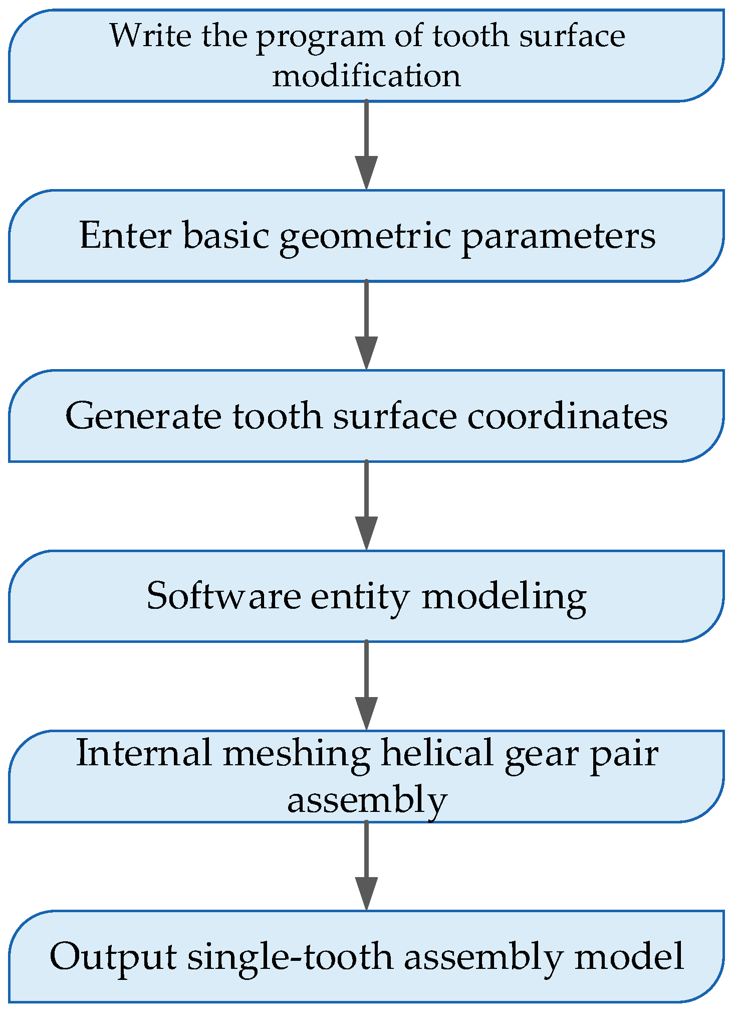
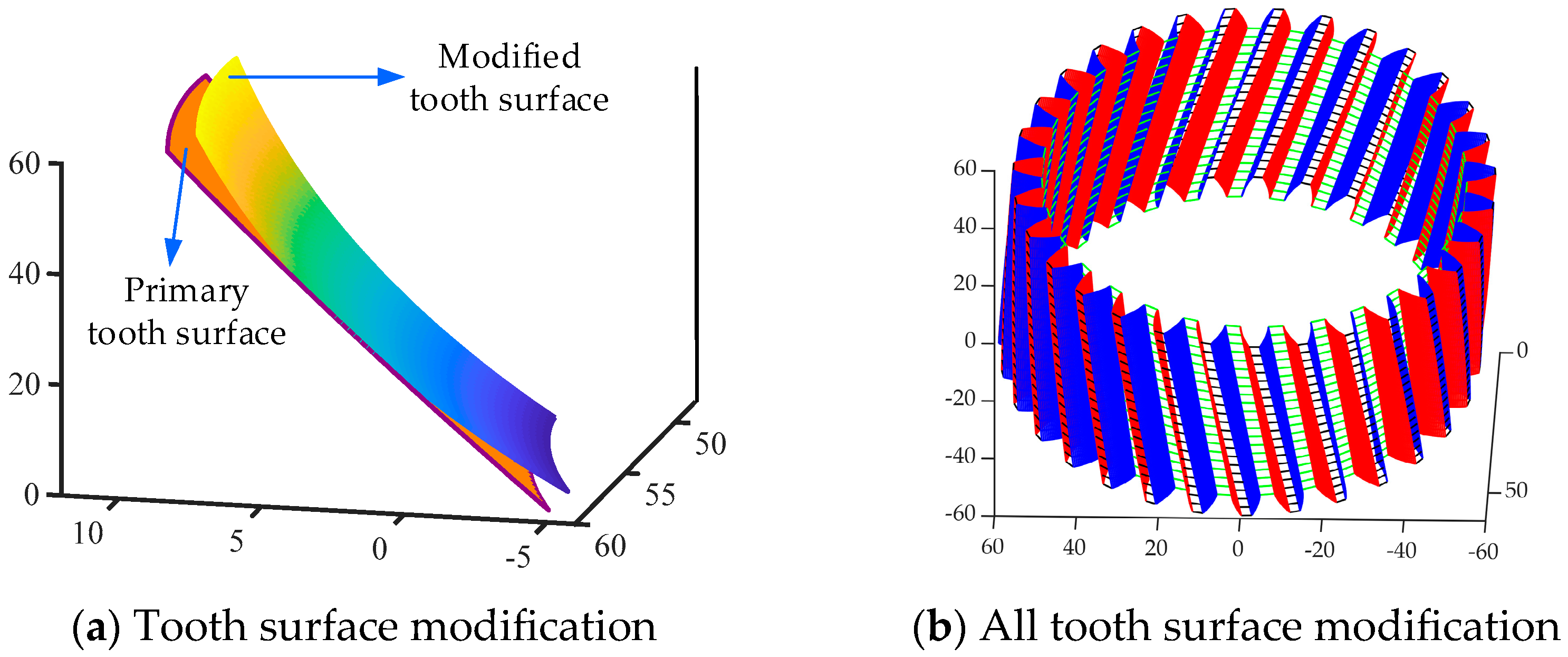
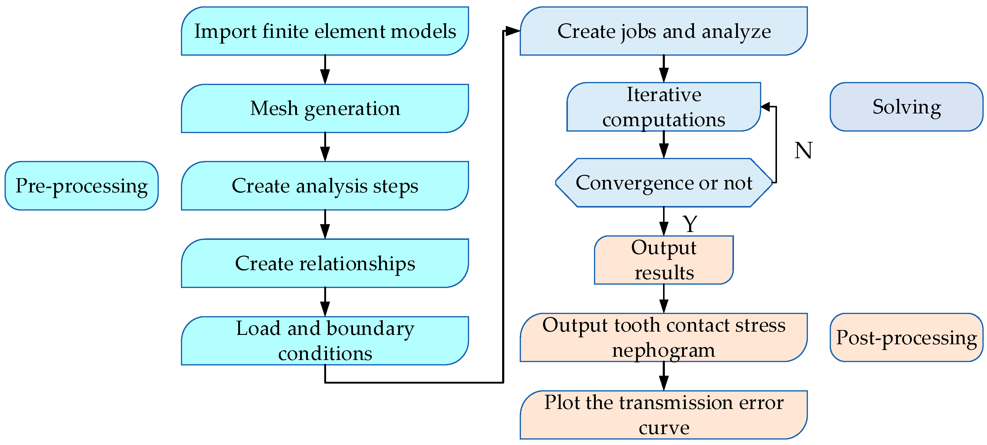
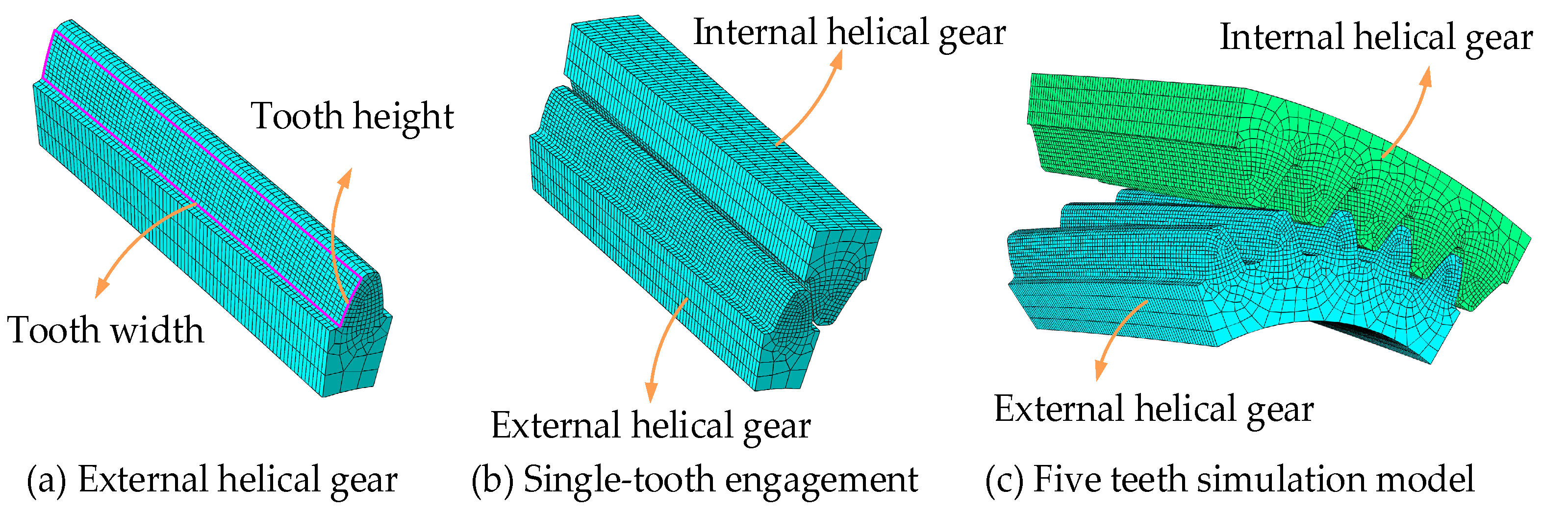
4. Digital Modeling of an Internal Helical Gear Pair

The digital model of the internal helical gear pair is established based on the given equation, with its basic geometric parameters being listed in Table 1, while the external helical gear tooth profile modification coefficients ( a c ) and tooth longitudinal modification coefficients ( a p ) are divided into five groups, as listed in Table 2. Matlab R2022b software is used to develop the calculation program for the helical gear tooth surface model, with the process illustrated in Figure 11. After inputting the parameters, the split-arc interpolation algorithm is applied to calculate the number of tooth profile iterations. A numerical iteration method is proposed to solve the coordinate equations of the modified tooth surface, and the coordinates of the tooth surface points are output. The coordinates of both the modified and unmodified tooth surfaces are shown in Figure 12a. The coordinates of the tooth top circle and the tooth root circle are applied to generate the point cloud data, which constructs the digital tooth surface, as illustrated in Figure 12b.
The gear pair assembly diagram (Figure 13) was obtained by applying constraints during the mating process of two gears. Before importing the complete assembly model into ABAQUS, it was segmented into a single meshing tooth pair. Through pattern replication and merging in ABAQUS, a five-tooth simulation model was generated. Compared to the full model, this approach maintains transmission periodicity while significantly reducing computational time.
Finite element analysis was conducted for five profile modification configurations using the parameters listed in Table 3. The gear meshing simulation process (Figure 14) involved three phases: (1) pre-processing involving model simplification, mesh generation, material property assignment, analysis step definition, and load and boundary condition application; (2) solution; and (3) post-processing through custom-developed algorithms for data extraction and full-field loaded contact pattern visualization.
The three-dimensional single-tooth meshing model was imported into ABAQUS simulation software, with its mesh properties configured as shown in Figure 15 using hexahedral elements. To enhance simulation accuracy, the tooth surface mesh density was increased by setting local seeds to 80 along the tooth width direction and 10 along the tooth height direction (Figure 15a), The single-tooth model was then patterned (Figure 15b) and merged into a five-tooth simulation model (Figure 15c), significantly improving both computational efficiency and accuracy.
The script file was utilized to extract contact stress cloud chart of the external helical gear. A Python 3.7 script was used to record the maximum contact stress value at each moment into a file, and the maximum contact stress cloud charts were combined to generate the meshing distribution area chart [21], including five modification schemes and two design load conditions. Figure 16A,B, respectively, display the contact stress distributions under 1000 Nm and 2500 Nm load conditions.
The figure reveals an elliptical contact pattern with tapered ends across the tooth surface’s integral meshing area, where maximum contact stress occurs at the elliptical center and exhibits radial decay. The simulation results of Group e1 and e2 present the unmodified helical gear’s contact contour plot, demonstrating near-complete surface contact within the meshing zone. In Groups a1/a2, c1/c2, and d1/d2, the maximum contact stress deviates from the tooth surface center, with significantly higher stress observed on the initial meshing tooth compared to subsequent teeth. Group b1/b2 demonstrates centralized maximum stress at the tooth surface center. When the design load increases from 1000 Nm to 2500 Nm, a wider contact area increases the probability of edge contact occurrence.
Analysis of Groups a1 and b1 reveals that when the tooth direction modification coefficient is held constant, an increase in the tooth profile modification coefficient causes the maximum contact stress to shift toward the tooth root in the contact zone. This modification also leads to an expansion of both the meshing zone along the tooth width and the overall contact area, significantly affecting the peak contact stress distribution on the tooth surface.
Analysis of Groups c and d reveals that maintaining a constant profile modification coefficient while increasing the longitudinal modification coefficient results in a narrower tooth contact and slower contact stress accumulation. Figure 17 presents the maximum stress (Figure 17A) and stress amplitude (Figure 17B), showing that the unmodified gear set (Group e) maintains relatively high stress amplitude. Comparative results indicate that Group a exhibits both the highest maximum contact stress as well as the largest stress amplitude among all modified gear sets, while the other three groups show minimal differences in stress amplitude. Notably, Group c achieves the lowest maximum stress value under identical loading conditions, suggesting benefits for extending gear service life.
The transmission accuracy of gears is affected by transmission error, which induces gear tooth vibration and accelerates tooth surface wear. Transmission error, defined as the angular deviation between the actual and theoretical rotation positions of the driven gear when the driver rotates at the theoretical angle during the rotating of the internal helical gears pair, is expressed as follows:
δ = ( φ 1 φ 1 0 ) z 1 / z 2 ( φ 2 φ 2 0 )
φ 1 denotes the actual rotation angle of the driving gear, while φ 2 represents the actual rotation angle of the driven gear, and φ 1 0 and φ 2 0 correspond to the theoretical rotation angles of the driving and driven gears, respectively. Here, z 1 and z 2 indicate the number of teeth of the internal helical gear and external helical gear, respectively.
In this model, the internal helical gear acts as the driver while the modified external helical gear serves as the driven gear. In the visualization, the XY data manager extracts the external gear’s instantaneous rotational radii to determine the gear pair’s transmission error, as illustrated in Figure 18. The computational results demonstrate that in the modified gear pair system, the transmission error under a 2500 Nm load is significantly lower than that observed under a 1000 Nm load condition. the main reason is that the heavy load increases the contact area of the tooth surface, which increases the smoothness of the gear transmission and reduces the transmission error and vibration when the teeth engage in and out.
The transmission error of the internal helical gear pair under five different sets of modification parameters is illustrated in Figure 18. The transmission error of the unmodified gear pair (Group e) exhibits a positive correlation with increasing load magnitude, and the value increased significantly from 9.23″ to 14.25″. Under the loading condition of 1000 Nm, the parameters for Group c are as follows: a c = 0.00004, a p = 0.00003. The transmission error curve of this group is the smoothest group among the four sets of data, and the amplitude is the smallest, which is 12.6″. At the 2500 Nm loading condition, the results indicate that Group b ( a c = 0.00008, a p = 0.0001) exhibits the smoothest operation among the five test sets, with the minimum amplitude of 10.2″ representing a 28.4% reduction compared to the unmodified configuration. This group has a significant effect on improving the transmission performance of the internal helical gear pair.
On the contrary, Group d ( a c = 0.00004, a p = 0.0001) in the two loading groups demonstrated the highest amplitude, reducing the meshing smoothness of the internal helical gear pair, resulting in elevated vibration and noise levels. The tooth profile modification coefficient is unchanged, and with the increase in the longitudinal modification coefficient, the transmission error of the external helical gear becomes larger and steeper, and the transmission smoothness of the internal meshing helical gear pair decreases. Consequently, practical applications should employ smaller longitudinal modification coefficients.

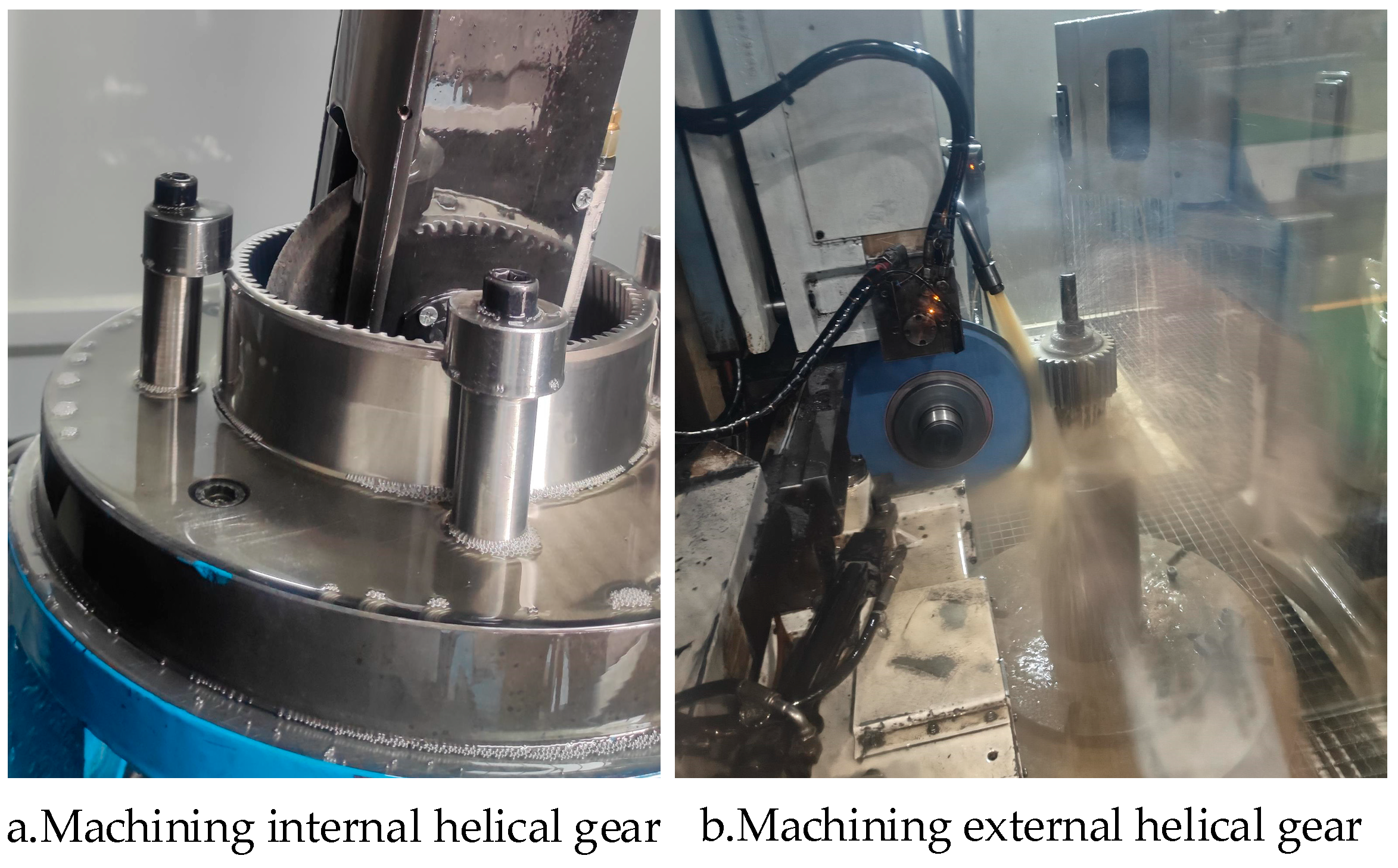
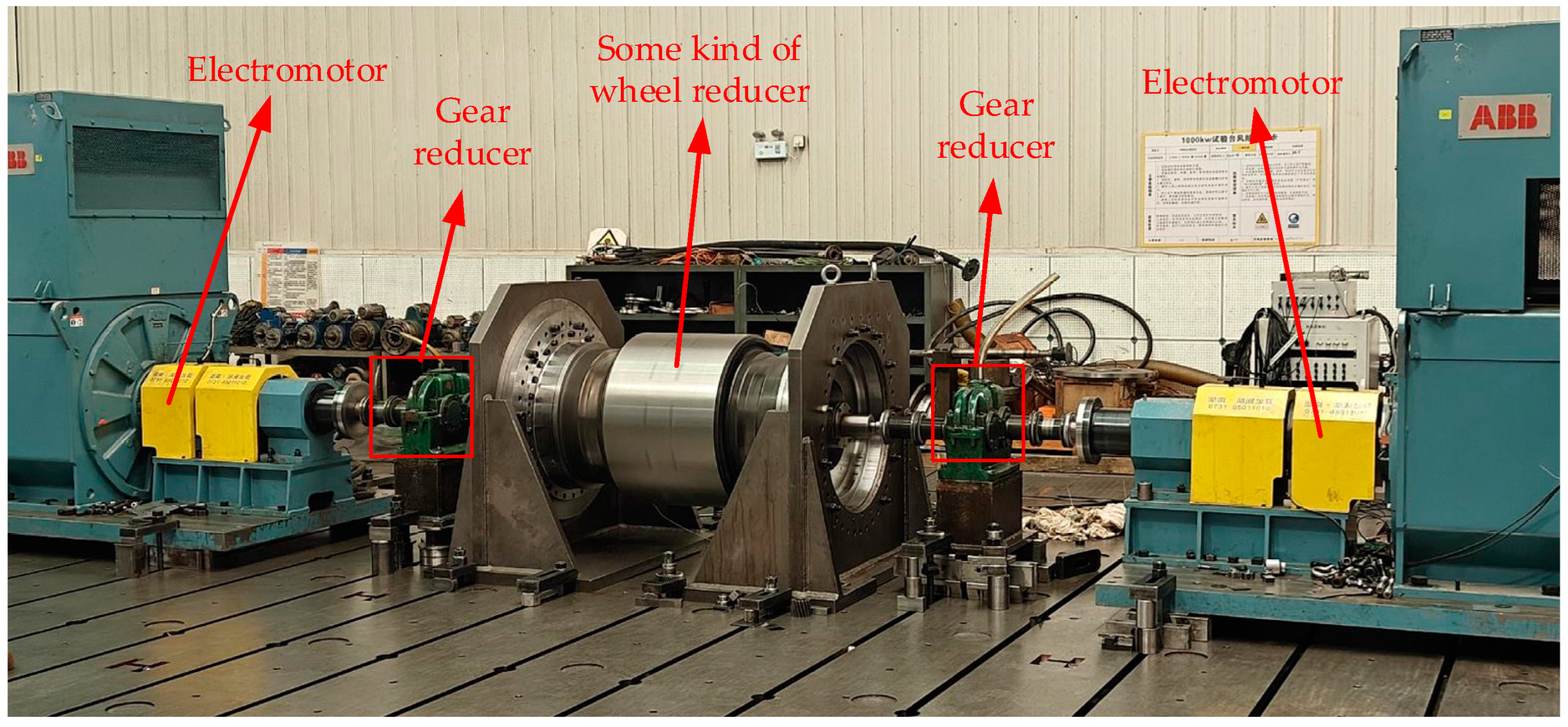
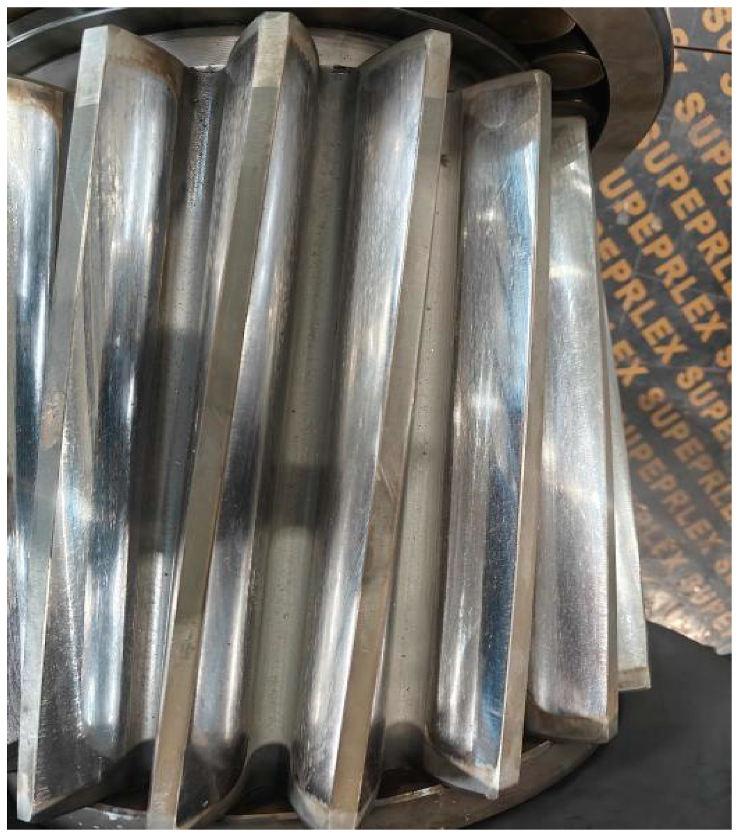
5. Experimental Verification

The simulation analysis revealed that Group b exhibited centralized meshing zones under both loading conditions with minimal transmission error. To validate these findings, a planetary gear set was manufactured using these optimized parameters. The machining process is illustrated in Figure 19. Figure 19a shows the internal helical gear production, and Figure 19b displays the external helical gear fabrication. The gear assembly was installed in a wheel-edge reducer where precise positioning ensured proper meshing alignment, and during testing, the reducer drove the internal helical gear pair. Figure 20 shows the experimental setup with two standard reducers mounted symmetrically, speed-converted motors, and drive motors at each end. After low-speed operation, the tooth contact patterns appear as shown in Figure 21.
As can be seen from Figure 21, the contact area appears in the middle area of the tooth surface of the topological modified external helical gear, and little edge contact exists at the tooth root and tooth width. The mean error is calculated by means of the transmission error obtained from the actual loading transmission experiment of the reducer. As shown in Figure 22, the green and purple curves represent the absolute and mean errors obtained from simulation, while the red and bule curves represent the absolute and mean errors obtained from the experiment, respectively. The mean values of transmission errors by means of experimentation and simulation are 330.65″ and 306.8″, respectively. The amplitude of the experiment transmission error curve reached 12.5″, increasing by 22.55% compared to simulation results. Due to the manufacturing error and assembly error of the planetary gear system, the 22.55% deviation between the experiment and simulation is appropriate.

6. Conclusions

  • This study proposes a variable-diameter helical modification method for longitudinal correction, where the tooth width center remains unmodified while both sides undergo material reduction. Combined with tooth profile modification, this approach is used to study the influence of modification on the transmission performance of an internal helical gear pair.
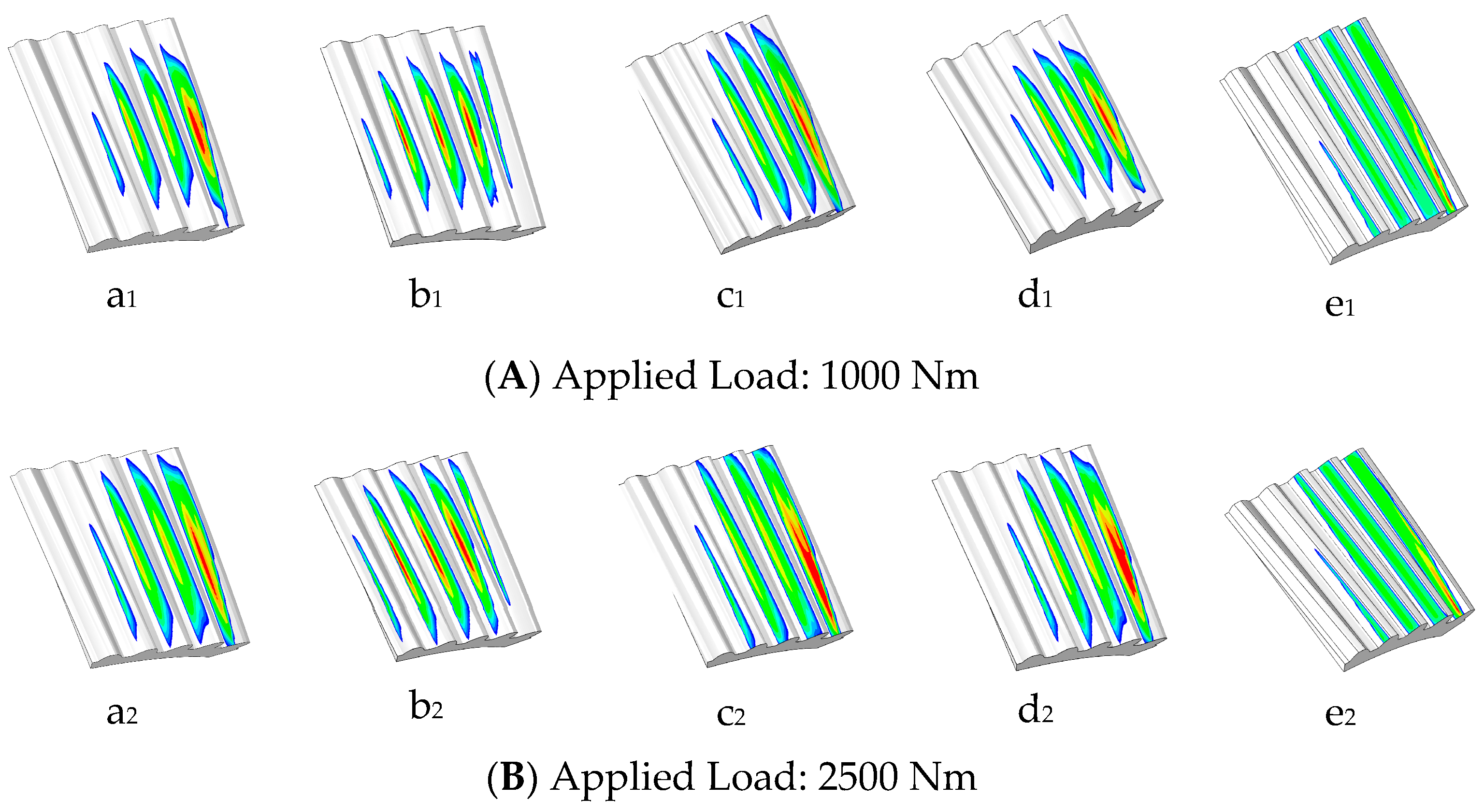
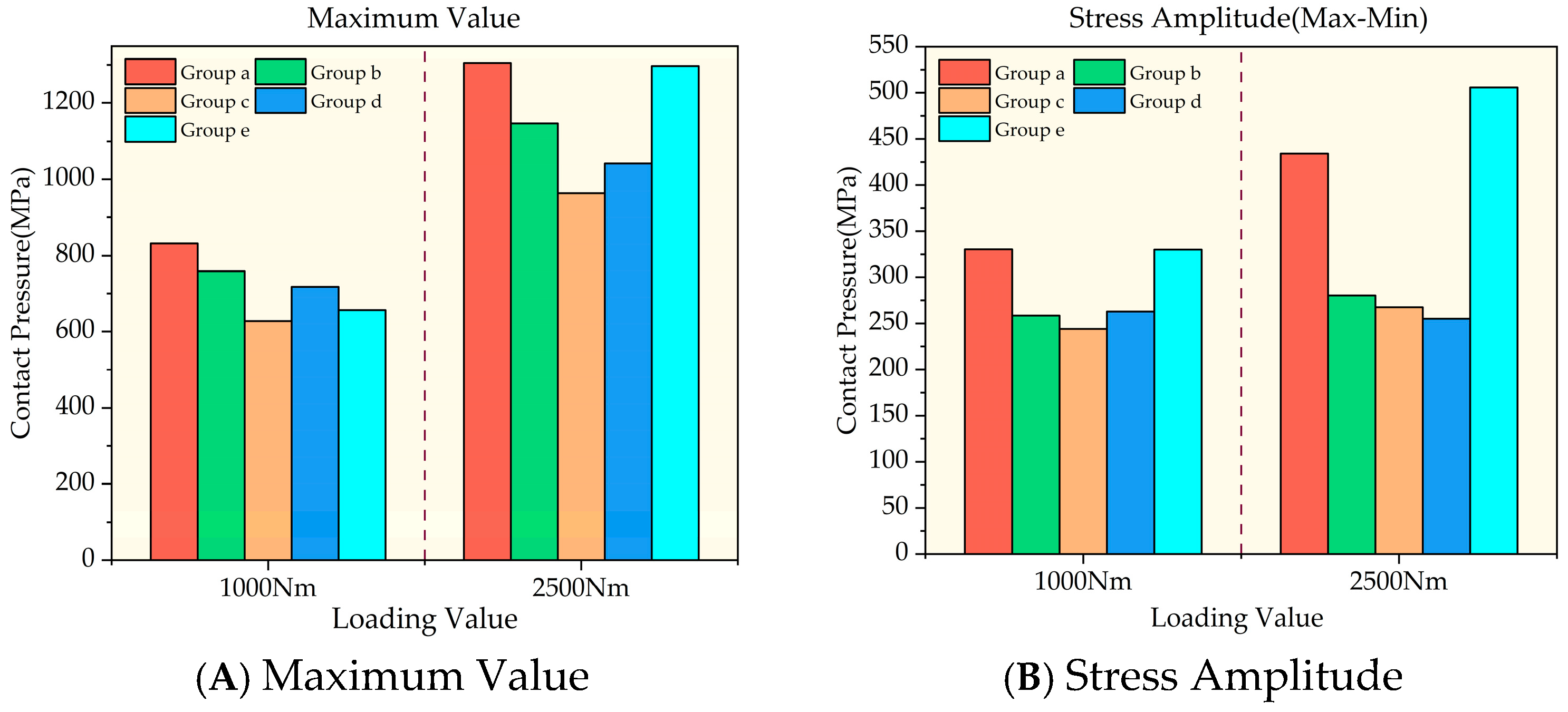
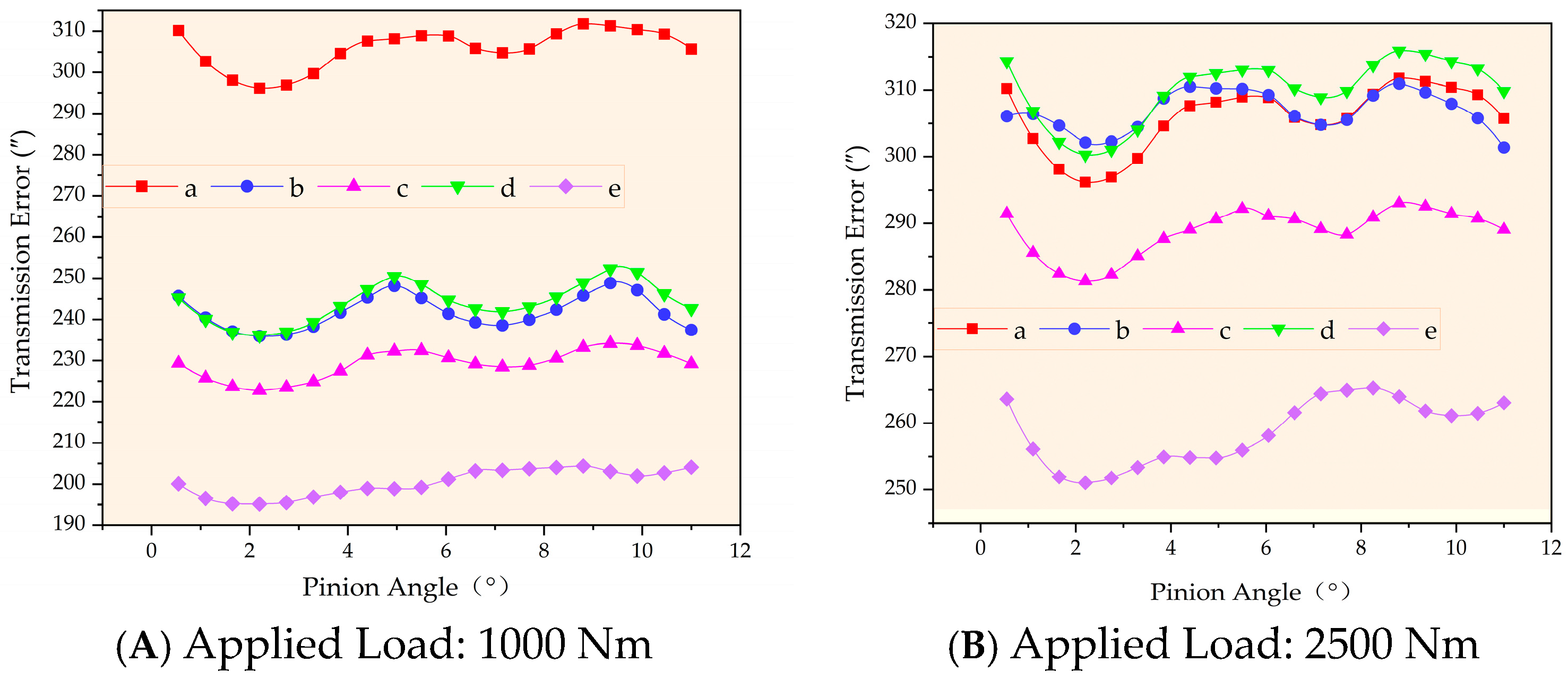
  • The simulation results demonstrate that maintaining the longitudinal modification coefficient constant while increasing the profile modification coefficient shifts the maximum contact stress toward the tooth root. Concurrently, the meshing area expands longitudinally, significantly affecting the peak contact stress distribution. Conversely, keeping the profile modification coefficient constant while increasing the longitudinal modification coefficient narrows the contact area and lowers the stress concentration. Notably, the longitudinal modification coefficient has a greater influence on transmission error than the profile modification coefficient, as it decreases the meshing area, thereby increasing transmission instability during gear engagement and disengagement.
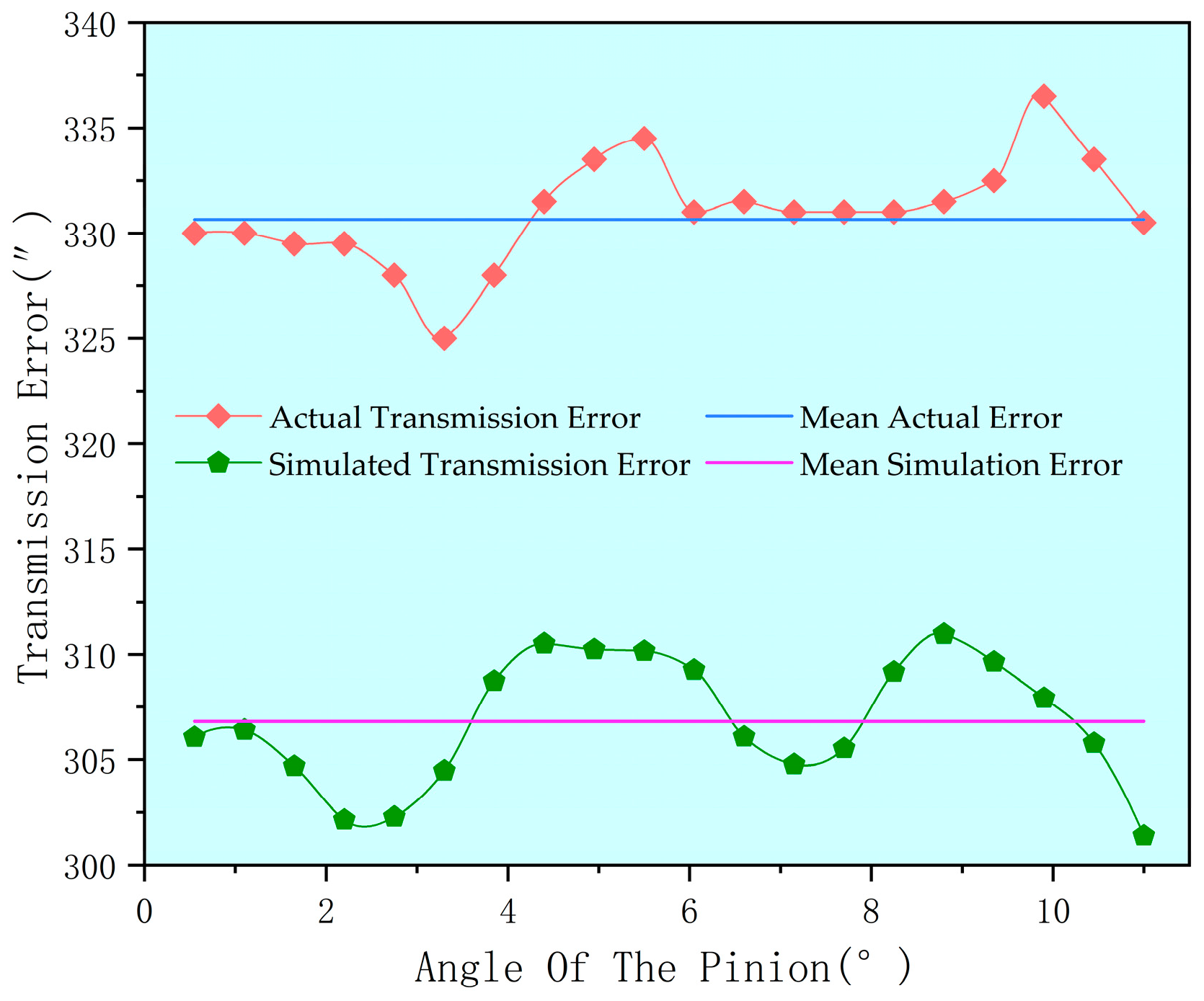
  • The modified gear pair exhibited a 28.4% lower simulated transmission error than the unmodified version under 2500 Nm loading conditions. The amplitude of the experiment transmission error curve reached 12.5″. Based on these results, prototype gears were manufactured and tested. The experiments confirmed the modification effectiveness, demonstrating improved performance in the internal helical gear pair.

Author Contributions

Conceptualization, J.X.; methodology, J.S.; software, X.W.; validation, S.L.; formal analysis, J.S.; investigation, S.L.; writing—original draft preparation, X.W.; writing—review and editing, J.S.; supervision, J.S. All authors have read and agreed to the published version of the manuscript.

Funding

This research was funded by the National Natural Science Foundation of China (No. 52375052), the Natural Science Foundation of Henan Province (No. 242300421183), the Key R&D Program of Henan Province (No. 241111230300) and Frontier Exploration Project of Longmen Laboratory (No. LMQYTSKT027).

Data Availability Statement

Data are contained within the article.

Conflicts of Interest

Author Shilin Lian was employed by Zhengzhou Institute of Machinery (Zhengzhou) Transmission Technology Co., Ltd. The remaining authors declare that the research was conducted in the absence of any commercial or financial relationships that could be construed as a potential conflict of interest.

References

  1. Wang, R.Y.; Yang, J.W.; Wang, J.H. Study on the effect of displacement design on the dynamic characteristics of helical gear system. Mech. Transm. 2024, 48, 1–8. [Google Scholar]
  2. Jia, B. Research on the Dynamic Characteristics Analysis and Shape Optimization of Helical Gears for High-Speed Trains under Multiple Working Conditions. Master Thesis, Dalian Jiaotong University, Dalian, China, 2023. [Google Scholar]
  3. Zhao, H.Y.; Zhi, Z.G.; Cao, J.F. Design analysis of helical gear trimming for aerospace gearboxes based on KISSsoft. Mech. Res. Appl. 2023, 36, 67–70. [Google Scholar]
  4. Lin, T.; He, Z. Analytical method for coupled transmission error of helical gear system with machining errors, assembly errors and tooth modifications. Mech. Syst. Signal Process. 2017, 91, 167–182. [Google Scholar] [CrossRef]
  5. Wang, H.L. Helical Gear Topology Trimming Method Based on Functional Requirements and Its Gear Grinding Realization. Ph.D. Thesis, Northwestern Polytechnical University, Xi’an, China, 2016. [Google Scholar]
  6. Hua, X.J.; Du, H.; Xie, X.; Huang, W.P.; Tian, Z.X.; Yin, B.F.; Liu, J.F. Noise reduction analysis of involute helical gears with short profile trimming. Appl. Acoust. 2020, 39, 430–437. [Google Scholar]
  7. Zhao, Z.Q. Topological Modification and Load Bearing Contact Analysis of Helical Gears Ground by Forming Method. Master Thesis, Henan University of Science and Technology, Luoyang, China, 2020. [Google Scholar]
  8. Chen, J.J.; Zhu, R.P.; Chen, W.F.; Li, M.M.; Yin, X.M.; Zhang, X.X. General Meshing Modeling and Dynamic Characteristics Analysis of Helical Gear Pair with Tooth Surface Deviation. Iran. J. Sci. Technol. Trans. Mech. Eng. 2024, 48, 1623–1641. [Google Scholar] [CrossRef]
  9. Jiang, J.K.; Fang, Z.D.; Su, J.Z. Design and machining of helical gear trimming with high-order transmission error. J. Harbin Inst. Technol. 2014, 46, 43–49. [Google Scholar]
  10. Yang, J.J.; Wang, J.J.; Mao, S.M. Analysis of Transmission Performance of Helical Gear Based on High-Order Modification Design. Appl. Mech. Mater. 2013, 2773, 236–240. [Google Scholar] [CrossRef]
  11. Yan, P.F.; Liu, H.; Gao, P.; Zhang, X.; Zhan, Z.B.; Zhang, C. Optimization of distributed axial dynamic modification based on the dynamic characteristics of a helical gear pair and a test verification. Mech. Mach. Theory 2021, 163, 104371. [Google Scholar] [CrossRef]
  12. Wu, Y.J.; Wang, J.J.; Han, Q.K. Static/dynamic contact FEA and experimental study for tooth profile modification of helical gears. J. Mech. Sci. Technol. 2012, 26, 1409–1417. [Google Scholar] [CrossRef]
  13. Zhang, X.J.; Jia, C.; Hou, X.Y.; Guo, F.; Zhai, J. Topological modification and simulation of helical gears with axial angle error. J. Xi’an Univ. Technol. 2018, 38, 28–34. [Google Scholar]
  14. Jia, C.; Fang, Z.D.; Yao, L.G.; Zhang, J. Tooth flank modification to reduce transmission error and mesh-in impact force in consideration of contact ratio for helical gears. Proc. Inst. Mech. Eng. Part C J. Mech. Eng. Sci. 2021, 235, 4475–4493. [Google Scholar] [CrossRef]
  15. Wang, Y.Z.; Liu, Y.; Tang, W.; Liu, P. Parametric finite element modeling and tooth contact analysis of spur and helical gears including profile and lead modifications. Eng. Comput. 2017, 34, 2877–2898. [Google Scholar] [CrossRef]
  16. Zhao, Z.F.; Yang, Y.; Ma, H.; Wang, H.X.; Tian, H.X.; Han, C.Y. Meshing characteristics of spur gear pairs with tooth modification under different assembly errors and sensitivity analysis for impact factors. J. Mech. Sci. Technol. 2022, 37, 149–162. [Google Scholar] [CrossRef]
  17. Bejar, F.; Perret-Liaudet, J.; Bareille, O.; Ichchou, M.; Fontana, M. Review and benchmarking study of different gear contact analysis software in terms of the static transmission error response. Results Eng. 2024, 22, 102286. [Google Scholar] [CrossRef]
  18. Ahmad, H.; Cheng, W.; Xing, J.; Wang, W.T.; Du, S.H.; Li, L.Y.; Zhang, R.Y.; Chen, X.F.; Lu, J.Q. Deep learning-based fault diagnosis of planetary gearbox: A systematic review. J. Manuf. Syst. 2024, 77, 730–745. [Google Scholar] [CrossRef]
  19. Pedrero, J.I.; Sánchez-Espiga, J.; Sánchez, M.B.; Pleguezuelos, M.; Fernández-Del-Rincón, A.; Viadero, F. Simulation and validation of the transmission error, meshing stiffness, and load sharing of planetary spur gear transmissions. Mech. Mach. Theory 2024, 203, 105800. [Google Scholar] [CrossRef]
  20. Litvin, F.L.; Fuentes, A.; Gonzalez-Perez, I.; Carvenali, L.; Kawasaki, K.; Handschuh, R.F. Modified involute helical gears: Computerized design, simulation of meshing and stress analysis. Comput. Methods Appl. Mech. Eng. 2003, 192, 3619–3655. [Google Scholar] [CrossRef]
  21. Nie, S.W.; Chen, J.Y.; Liu, S.H. Research on noise reduction of drive axle hypoid gear based on tooth surface mismatch modification. Adv. Mech. Eng. 2024, 16, 16878132241228195. [Google Scholar] [CrossRef]
Figure 1. Schematic diagram of the planetary wheel.
Machines 13 00340 g001
Figure 2. Internal helical gear coordinate system. The pink area represents the tooth surface.
Machines 13 00340 g002
Figure 3. External helical gear coordinate system. The pink area represents the tooth surface.
Machines 13 00340 g003
Figure 4. Meshing coordinate system of internal helical gear pair.
Machines 13 00340 g004
Figure 5. Contact lines on an involute helical tooth surface.
Machines 13 00340 g005
Figure 6. Crowning of pinion tooth surface.
Machines 13 00340 g006
Figure 7. Topological modification of pinion shape. Regions 0: theoretical involute tooth surface; regions 1, 3, 6, 8: tooth profile and longitudinal modification; regions 4 and 5: longitudinal modification; regions 2 and 7: profile modification; curves a, b, c, d: boundary lines between each zone.
Machines 13 00340 g007
Figure 8. External helical gear tooth profile modification. The color-coded elements are represented as follows: the purple line represents the coordinate axis, the black dashed line indicates the theoretical tooth profile, the red solid line corresponds to the modified tooth profile, and the blue solid line denotes the effective generating line length.
Machines 13 00340 g008
Figure 9. Shape grinding motion diagram of modified helical gear.
Machines 13 00340 g009
Figure 10. Coordinate system for profile grinding of modified external helical gears.
Machines 13 00340 g010
Figure 11. Modeling process of internal helical gear pair assembly.
Machines 13 00340 g011
Figure 12. Point cloud data of the external helical gear tooth surface.
Machines 13 00340 g012
Figure 13. Assembly model of internal helical gear pair.
Machines 13 00340 g013
Figure 14. Abaqus simulation flowchart.
Machines 13 00340 g014
Figure 15. Finite element mesh model of an internal helical gear pair.
Machines 13 00340 g015
Figure 16. Cloud diagram of loading simulation results. (a1 and a2) a c = 0.00003, a p = 0.0001; (b1 and b2) a c = 0.00008, a p = 0.0001; (c1 and c2) a c = 0.00004, a p = 0.00003; (d1 and d2) a c = 0.00004, a p = 0.0001; (e1 and e2) a c = 0.0, a p = 0.0. The color mapping in the contour plot adheres to the rainbow spectrum, where the minimum data values are assigned to the blue end of the scale, transitioning through green and yellow for intermediate values, and culminating in red to denote the maximum values.
Machines 13 00340 g016
Figure 17. Stress situation under loading conditions.
Machines 13 00340 g017
Figure 18. Transmission error under load.
Machines 13 00340 g018
Figure 19. Machining of internal helical gear pair.
Machines 13 00340 g019
Figure 20. Establishment of the experimental test rig.
Machines 13 00340 g020
Figure 21. Contact area after modification.
Machines 13 00340 g021
Figure 22. Actual transmission error of modified external helical gear.
Machines 13 00340 g022
Table 1. Basic parameters of internal helical gear pair.
ItemsHelical GearInternal Helical Gear
Number of teeth3179
Helix directionleft-handleft-hand
Module3.53.5
Pressure angle/(°)2020
Helix angle/(°)1212
Tooth width/mm6060
Table 2. Modification parameters of external helical gears.
GroupTooth Profile Modification Factor ( a c )Tooth Modification Coefficient Factor ( a p )
A0.000030.0001
B0.000080.0001
C0.000040.00003
D0.000040.0001
E0.00.0
Table 3. Simulation model parameters.
ItemValue
Material density/kg/m37.85 × 103
Poisson’s ratio0.29
Modulus of elasticity/MPa2.05 × 105
Unit typeC3D8I
Friction factor0.06
Number of seeds localized in tooth width80
Number of seeds localized in tooth height10
Loading value/Nm1000; 2500
Disclaimer/Publisher’s Note: The statements, opinions and data contained in all publications are solely those of the individual author(s) and contributor(s) and not of MDPI and/or the editor(s). MDPI and/or the editor(s) disclaim responsibility for any injury to people or property resulting from any ideas, methods, instructions or products referred to in the content.

