Article

Hybrid Brushless Wound-Rotor Synchronous Machine with Dual-Mode Operation for Washing Machine Applications

1
Department of Electrical Engineering, Sukkur IBA University, Sukkur 65200, Pakistan
2
Department of Electrical and Computer Engineering, Inha University, Incheon 22212, Republic of Korea
*
Author to whom correspondence should be addressed.
Machines 2025, 13(5), 342; https://doi.org/10.3390/machines13050342
Submission received: 10 March 2025 / Revised: 4 April 2025 / Accepted: 16 April 2025 / Published: 22 April 2025
(This article belongs to the Special Issue Recent Developments in Machine Design, Automation and Robotics)

Abstract

:
This paper proposes a hybrid brushless wound-rotor synchronous machine (HB-WRSM) with an outer rotor topology that can operate as a permanent magnet synchronous machine (PMSM), as well as an HB-WRSM. In the first part, the existing brushless wound-rotor synchronous machine (BL-WRSM) is modified into a hybrid model by introducing permanent magnets (PMs) in the rotor pole faces to improve the magnetic field strength and other performance variables of the machine. In the second part, a centrifugal switch is introduced, which can change the machine operation from HB-WRSM to PMSM. The proposed machine uses an inner stator, outer rotor model with 36 stator slots and 48 poles, making the stator winding a concentrated winding. The HB-WRSM is utilized for dual-speed applications such as washing machines that run at low speed (46 rpm) and high speed (1370 rpm). For high speed, to have a better efficiency and less torque ripple, the machine is switched to PMSM mode using a centrifugal switch. The results are compared with the existing BL-WRSM. A 2D model is simulated using ANSYS Electromagnetics Suite to validate the machine model and performance.

1. Introduction

Today’s electrical machines are extremely diverse in type and application, ranging from direct-current machines of a few horsepower used in portable devices and household appliances to MW-scale AC synchronous generators used in power plants that convert natural potential energy into electrical energy. Permanent magnet (PM) machines have been widely used in a variety of applications requiring a high power output performance due to their high efficiency, excellent power factor, and high power density [1]. However, recent challenges such as a high cost, scarcity, and risk of demagnetization have led researchers to explore alternatives that use fewer or no PMs. The magnets used in the PM machines contain rare earth materials (REMs) such as neodymium (Nd) and dysprosium (Dy), which are increasingly vulnerable to supply risks and pose environmental concerns in their production [2,3]. PM synchronous machines (PMSMs) face not only demagnetization issues but also fixed magnetic fields.
An alternative to PM machines is a wound-rotor synchronous machine (WRSM), which is a more cost-effective solution with a controllable rotor flux capability. WRSMs feature rotors that contain copper windings as field windings, which require a separate power supply. Traditional WRSMs typically use slip rings and brushes to energize the rotor main field windings. However, this approach results in power losses in the form of heat and wasted energy, which can reduce the overall efficiency of the machine. In addition, maintenance and sparking issues make the use of slip rings and brushes undesirable. Despite these drawbacks, WRSMs offer several advantages, including the elimination of expensive PMs, simple variable speed control, and the ability to adjust the field current. These benefits allow for a higher efficiency under light-load conditions for variable-speed operations. Unlike WRSMs that use brushes to transfer power to the rotor, brushless WRSMs (BL-WRSMs) eliminate the need for brushes, reducing maintenance needs and the risk of mechanical failure. The transition to brushless designs addresses the long-standing need to eliminate brushes and slip rings from the system. In addition, the use of concentrated windings in BL-WRSMs improves harmonic component control, resulting in better performance and energy efficiency.
Previous studies have explored various machine topologies to enable a brushless operation through alternative stator winding configurations, inverter arrangements, and power control strategies. Each approach offers distinct advantages and trade-offs in terms of system performance, complexity, and cost. The impact of different stator winding designs on machine behavior has been extensively analyzed [4,5,6,7,8], with particular focus on specialized configurations such as open-end and semi-open stator windings [9,10]. These topologies, especially when driven by coils operating at different frequencies, can generate magnetic motive force (MMF) harmonics that support a brushless operation. However, they often require additional stator coils and inverters, leading to increased system complexity and costs.
Alternatively, the use of single-, dual-, or multi-inverter systems has also been investigated to improve the performance and flexibility of brushless machines [10,11,12,13,14]. Some researchers have proposed modified inverters that operate at different frequencies to optimize system performance [15,16]. These inverters power harmonic windings and can be operated independently or in combination. This approach improves operational flexibility but increases complexity, weight, and cost due to the need for additional inverters. Other topologies use thyristor switches, single-phase inverters, and rectifiers to regulate the power injection for brushless operation [12,17,18]. Thyristor switches are used to control the injected supply power for brushless operation, and rectifiers can also be used for the same purpose. However, these components introduce increased power losses, system complexity, and costs, making them difficult to implement in cost-sensitive applications.
This work examines the design, analysis, and performance of a hybrid brushless WRSM (HB-WRSM). This study seeks to offer a comprehensive understanding of the present advancements in hybrid brushless machines and their potential for future growth and utilization in industries such as renewable energy generation, electric vehicles, and industrial automation [19,20]. The HB-WRSM provides several advantages over conventional electric machines, such as a higher torque density, improved efficiency, and reduced maintenance requirements. These advantages make it an ideal choice for a variety of applications, including electric vehicles and industrial automation systems. The proposed machine incorporates PMs on the rotor pole faces of a conventional BL-WRSM. By embedding magnets in the outer rotor, the motor can operate at higher speeds, which broadens its potential range of applications and solves the efficiency issues commonly observed in BL-WRSMs [19]. This HB-WRSM configuration is particularly suitable for applications that require different performance characteristics depending on the mode of operation, such as washing machines (e.g., wash and spin modes). The washing machine controller is assumed to limit the operating current and protect against short circuits that could completely demagnetize the magnet [21]. The performance of the proposed HB-WRSM is evaluated by comparing it with a BL-WRSM and conventional WRSM (C-WRSM) [22].

2. The Latest Brushless Technology and Its Applications

WRSMs are a type of synchronous machine in which the rotor is equipped with field windings supplied through brushes and slip rings. WRSMs have several advantages over other types of electric machines. Notably, they do not require expensive permanent magnets, which reduces the overall system cost and makes them suitable for a wide range of applications. In addition, the controllability of the rotor excitation current allows for flexible speed operation and improved efficiency under various load conditions from medium to high speeds. Despite these advantages, WRSMs face several limitations. The biggest of these is their reliance on brushes and slip rings, which introduces mechanical complexity, increases maintenance requirements, and leads to additional power losses and a lower overall efficiency.

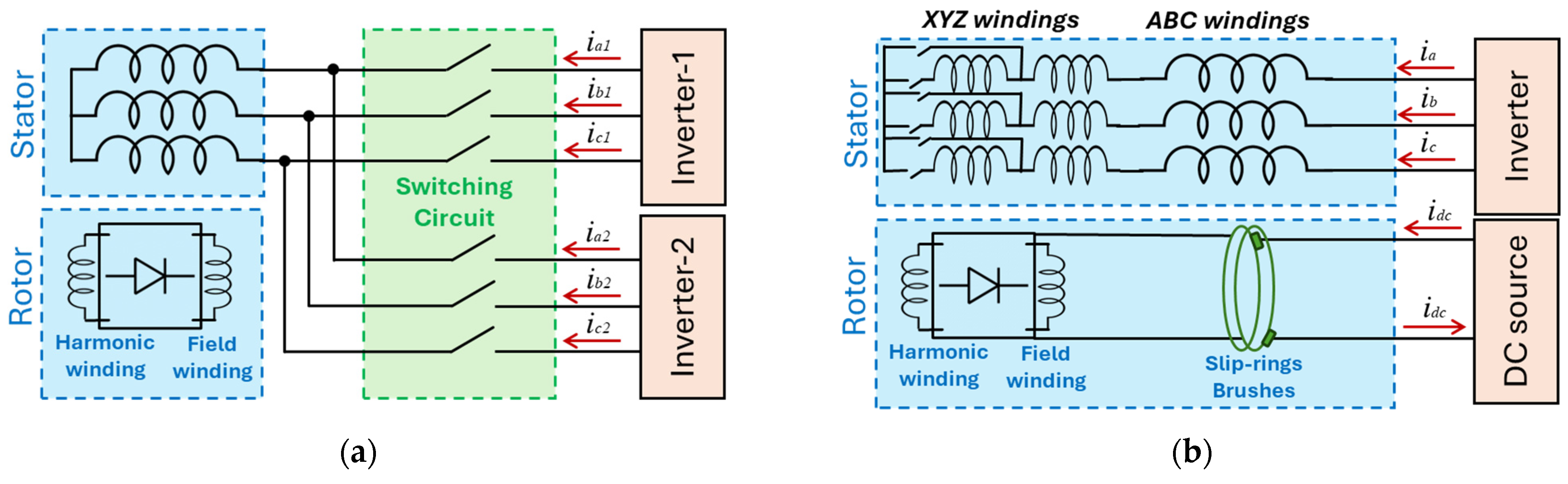
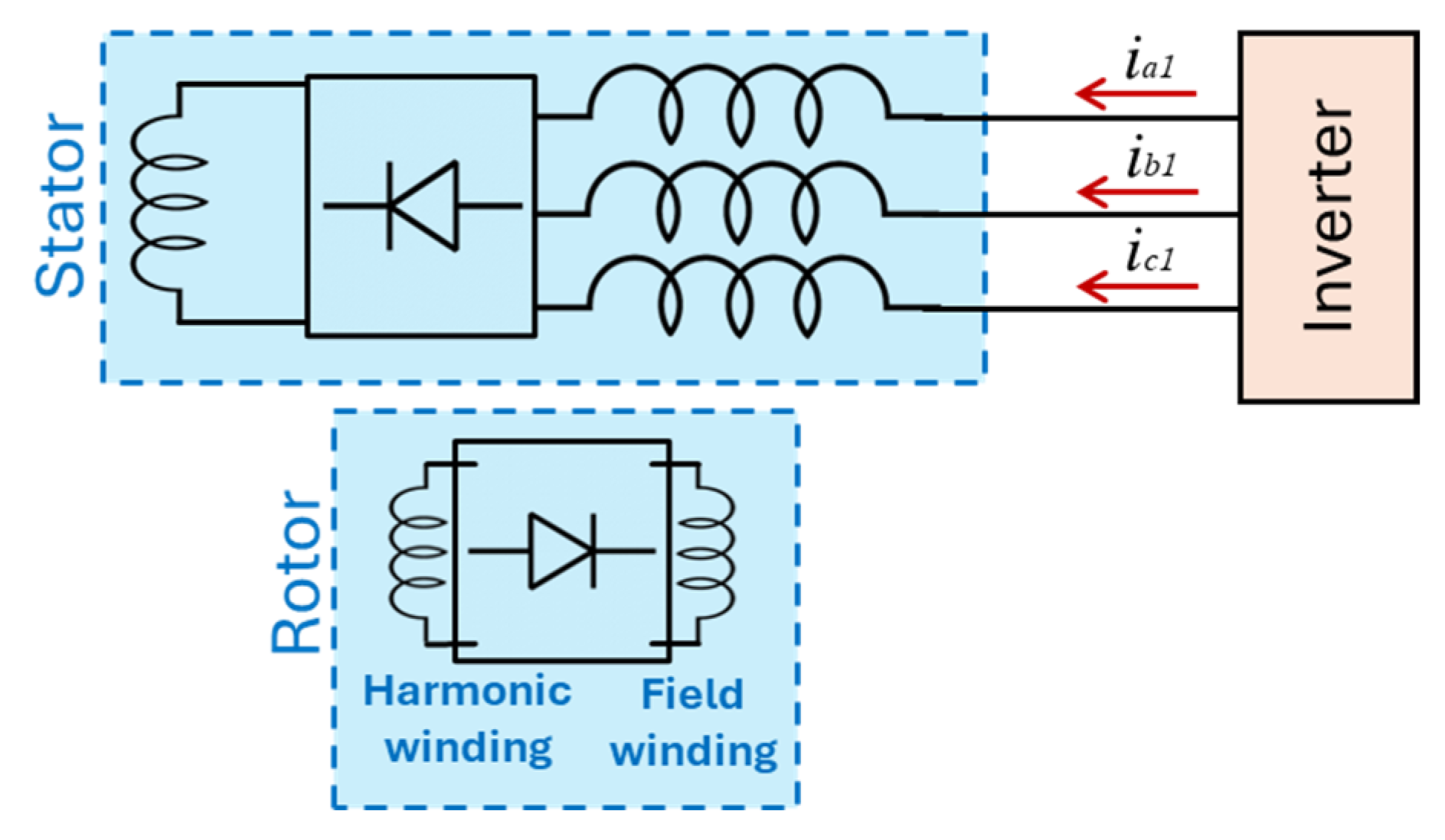
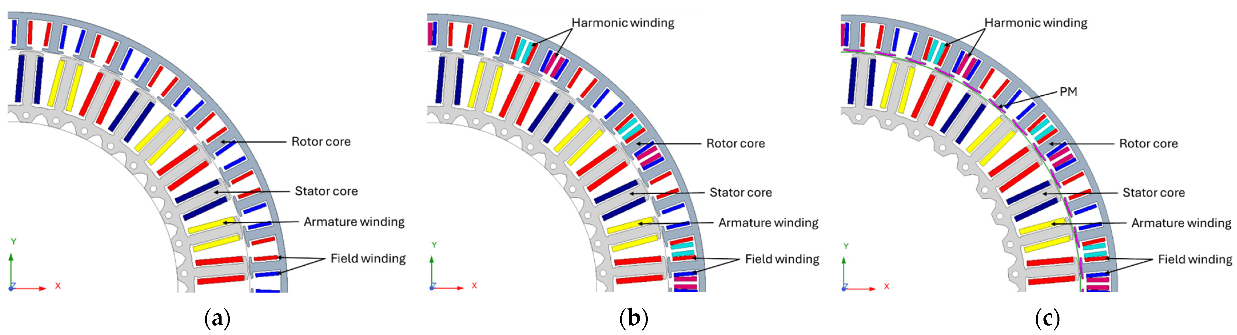
2.1. The Latest Brushless Technology

In this section, we first provide a detailed analysis of the characteristics of HB-WRSMs based on a comprehensive review of the literature on various brushless techniques explored in previous research and commercial applications since 2015.
In [19], the authors proposed a brushless solution based on a modified inverter design that utilizes time harmonics in contrast to the conventional approach. This approach allows the armature winding to supply both fundamental and third harmonic current components. However, it requires a complex inverter design and control technique. In [15], the author proposed a brushless technique that incorporates additional thyristor switches connected in parallel with the three-phase armature winding. These switches are activated at the zero-crossing points of each phase current, generating a third harmonic component.
In [23], the three-phase supply currents to the stator windings are phase-shifted by 180 degrees. By continuously switching these currents through a thyristor during each electrical period, a third harmonic component is generated. This harmonic component is subsequently rectified using a diode, as illustrated in Figure 1a. In [24], a novel method to switch between C-WRSM and BL-WRSM is implemented using a thyristor drive circuit; however, this increases the cost and volume of the drive system, as shown in Figure 1b.
In [25], a BL-WRSM topology was proposed utilizing a three-phase rectifier. The stator winding receives a standard three-phase current from the inverter, and the rectifier links the output to the neutral of the Y-connected armature winding. This design generates an additional third harmonic MMF component in the airgap, which is then used to induce an harmonic voltage and current in the harmonic winding. This harmonic current, in turn, drives the rotor field winding, allowing brushless operation, as shown in Figure 2.
The literature review suggests that the WRSM is a strong candidate to replace PMSMs because it provides comparable results on key performance metrics in comparisons between the two machines. In [13], two inverters were used to supply three-phase currents to two separate sets of stator windings. Based on this topology, a hybrid variant that incorporates PMs to improve high-performance performance was introduced in [16]. This configuration received some attention, leading to a new stator topology in [26], where two sets of stator windings with different numbers of series turns were employed. This topology, however, relied on a single inverter to supply a three-phase current to the stator windings, which increased the control complexity and copper losses and consequently reduced the overall efficiency compared to a C-WRSM. Shortly after, another hybrid variant with consequent magnets on the rotor poles was introduced in [10], improving machine performance. Further optimization of this machine topology was carried out using a genetic algorithm in [27].

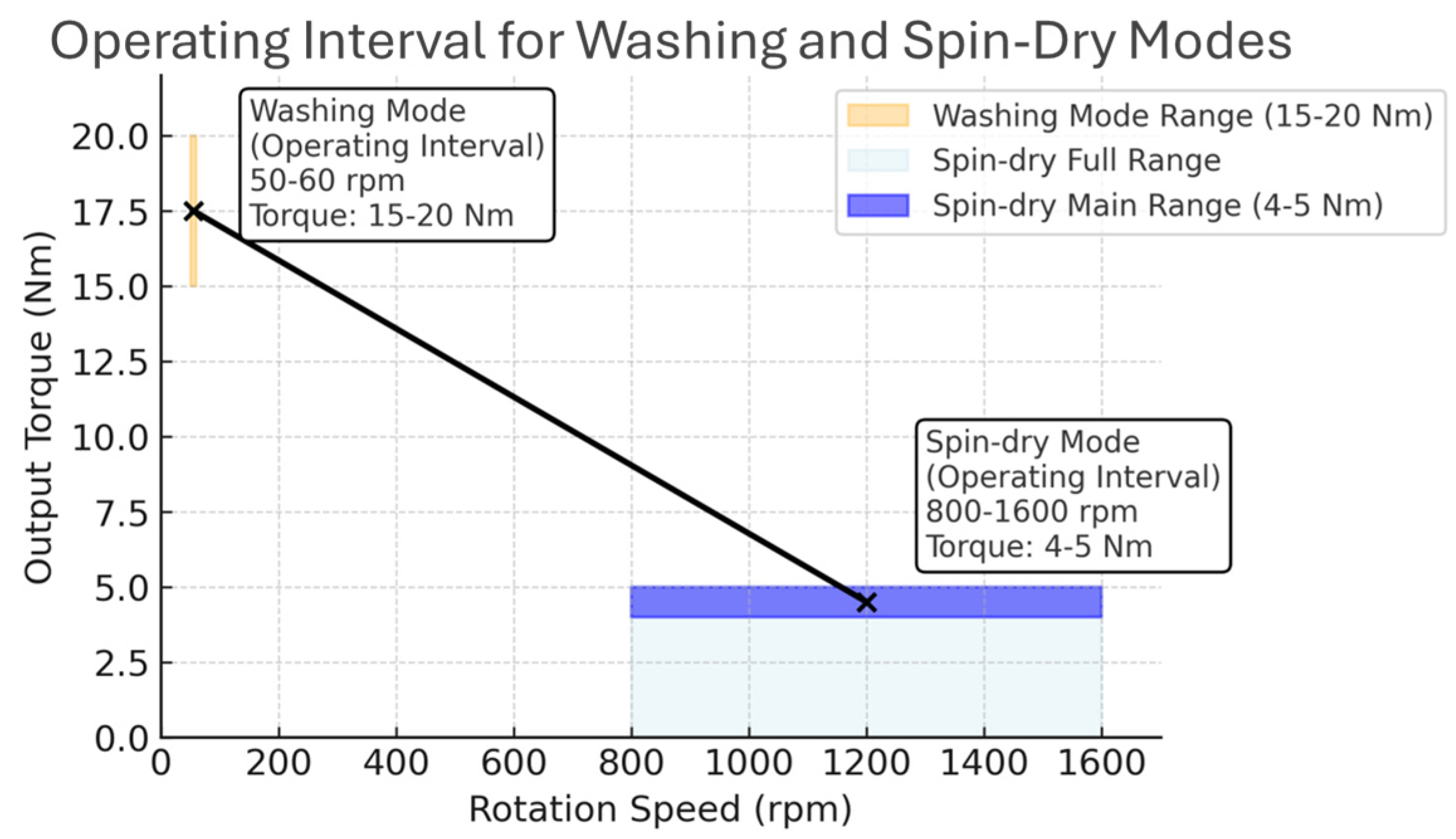
2.2. Dual Speed Applications

The ever-increasing need for electrical energy, along with environmental concerns, has raised the demand for variable-speed drives in low-cost, high-volume applications such as electric fans, washing machines, and home appliances. Currently, many of these applications use simple constant-speed drives, resulting in a degraded efficiency. They can benefit from variable-speed operation, which offers significant energy savings, increased dependability, and provides better process control. The main reason variable-speed drives have not penetrated such cost-sensitive applications is that they are more expensive than fixed-speed drives [28].
Washing operations can be separated into two major cycles: the wash cycle and the spin-dry cycle. During the washing cycle, the drum rotates at a relatively low speed, between 50 and 60 rpm, allowing clothes to tumble for effective cleaning. In contrast, the spin-dry cycle involves removing residual water from the laundry by utilizing centrifugal forces, achieved by drying the drum at higher speeds, typically from 800 to 1600 rpm [29]. The torque requirements differ significantly between the two cycles: the wash cycle demands a torque of approx. 15–20 Nm, while the spin-dry cycle requires a lower torque of around 3–5 Nm, as illustrated in Figure 3 [30].
Conventional washing machines were driven using belts, which generated significant losses and noise. The first direct-driven motor for washing machines was developed by Fisher and Paykel Appliances Ltd., Auckland, New Zealand [31]. The commercial model released in 2004 was a 36-slot, 48-pole PM machine operating at 1100 rpm [31]. Since then, the external rotor 36-slot, 48-pole configuration has been used by various manufacturers [32]. Figure 4a–d show different brands employing the 36/48 topology with segmented rotor magnets.

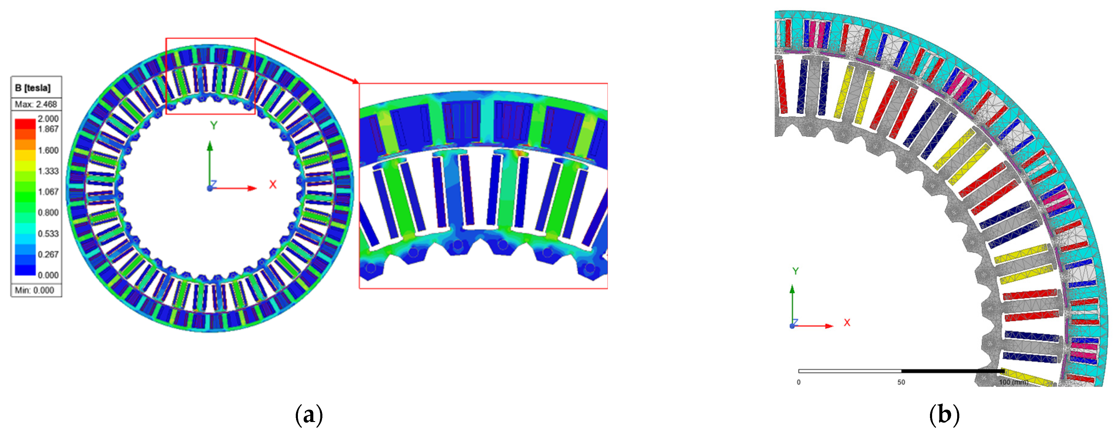
3. Simulation Results

The proposed machine uses an outer rotor, inner stator design with a novel winding topology. The 2D diagrams of the baseline machines are shown in Figure 5. In the proposed HB-WRSM design, the stator is equipped with three-phase windings placed in 36 slots, and it features 48 poles with PMs on the rotor pole faces, as shown in Figure 5c.
For brushless operation, the stator must be equipped with specialized windings that produce MMF to excite the rotor’s main field winding. Thus, the rotor is designed with two sets of windings: one referred to as the harmonic or excitation winding, and the other as the main field winding. Although various techniques for achieving brushless operation have been proposed, as in the literature review, the brushless operation technique used in this study is shown in Figure 6 to provide better clarity for the reader.
To achieve brushless operation in the proposed topology, the stator three-phase winding is fashioned to be a double-layer concentrated winding, as shown in the winding configuration diagram in Figure 7. The number of poles in the field winding should match that of the stator’s fundamental MMF component, which is 48 poles. With a 48-pole fundamental component, the excitation winding needs to have 24 poles, as illustrated in Figure 5. The rotor excitation winding pole pitch is two times that of the field winding as it intercepts the 0.5th harmonic airgap magnetic field.
For brushless operation, the stator MMF must generate two sets of dominant frequency components: a fundamental component with an harmonic order of 1 and a sub-harmonic component with an harmonic order of 0.5. As shown in Figure 6, the stator windings of the proposed machine are capable of generating this sub-harmonic component without the need for additional stator windings and/or additional inverters. As evidenced in the literature review, some papers have used additional inverters and switching devices to generate the desired harmonic components to achieve brushless operation, whereas this paper uses only one inverter and one set of concentrated three-phase stator windings.
The airgap harmonic field spectrum of a machine can be derived from its winding function, which represents the spatial distribution of conductors relative to the pole pitch. This function captures the collective contribution of all conductors across the machine’s airgap. By applying a Discrete Fourier Transform (DFT), typically implemented via the Fast Fourier Transform (FFT) algorithm, the winding distribution can be decomposed into its harmonic components, as illustrated in Figure 8 [33]. Figure 8 shows that the 0.5th-order sub-harmonic component of the proposed machine is higher than the fundamental (1st-order) component. The rotational speed of the sub-harmonic component in the air gap is given as below:
n s h = n s h = 120 f h p
where n s h represents the rotating speed of the harmonic component, n s is the fundamental synchronous speed, h is the harmonic number, f is the supplied frequency, and p is the number of poles. Using (1), the synchronous speeds of both the fundamental and sub-harmonic components are shown in Table 1. The fundamental synchronous speed will be 150 rpm when using the 48 poles in the proposed model at a fundamental frequency of 60 Hz. Observing the 0.5th-order sub-harmonic component in Figure 8, the rotating speed of the sub-harmonic component is 300 rpm, which is twice the speed of the fundamental component.
The fundamental MMF component seen by the rotor manifests as a DC component, while the sub-harmonic MMF appears as an AC component. To utilize this time-varying magnetic flux and generate an induced voltage, the rotor is equipped with an additional winding for field excitation. The voltage induced in the excitation winding is rectified via a rotating rectifier mounted on the rotor, producing a DC current that energizes the rotor’s field windings. A diagram of the rotor circuit, showing both the main field winding and the harmonic/excitation winding, is presented in Figure 9.
The design parameters of the proposed HB-WRSM topology and the C-WRSM and BL-WRSM are summarized in Table 2. As mentioned earlier, the proposed machine is used in a dual-speed washing machine, which initially operates in the washing mode at 46 rpm (18.4 Hz) and then switches to the drying mode at 1370 rpm (548 Hz). Therefore, the torque output and field current generation are different in both modes, which will be discussed in later sections.

4. Machine Performance Analysis

To evaluate the performance of the proposed HB-WRSM, 2D FEA simulations were conducted using ANSYS Maxwell software (Ver. 2022 R2). The simulations were performed with a time step of 1.2 ms, and an automated mesh with a maximum element length of 6 mm was applied. The output torque and power losses were obtained directly from the simulations, while the input power and efficiency were calculated analytically via post-processing. The main performance metrics are the output torque and current generated in the rotor field winding. The performance of two existing topologies (i.e., C-WRSM and BL-WRSM) has been simulated and presented in [34], and the results are compared with the simulation results of the HB-WRSM proposed in this study. For fair comparison, the input power and all other machine parameters have been kept the same for both the C-WRSM and BL-WRSM.

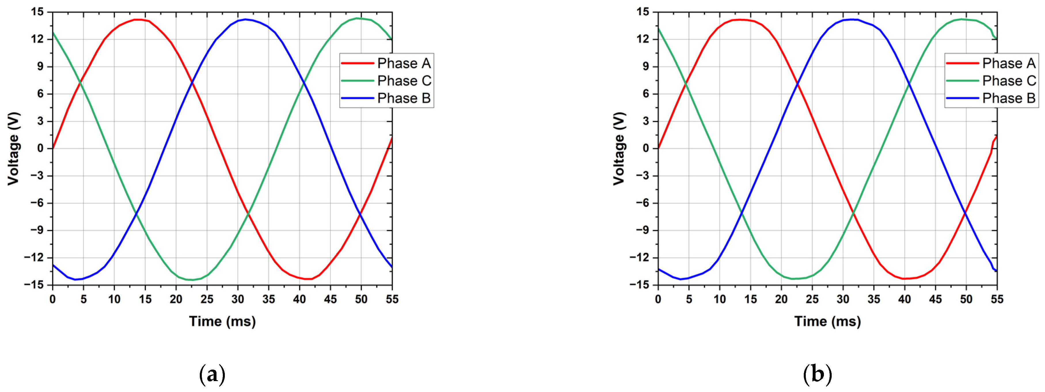
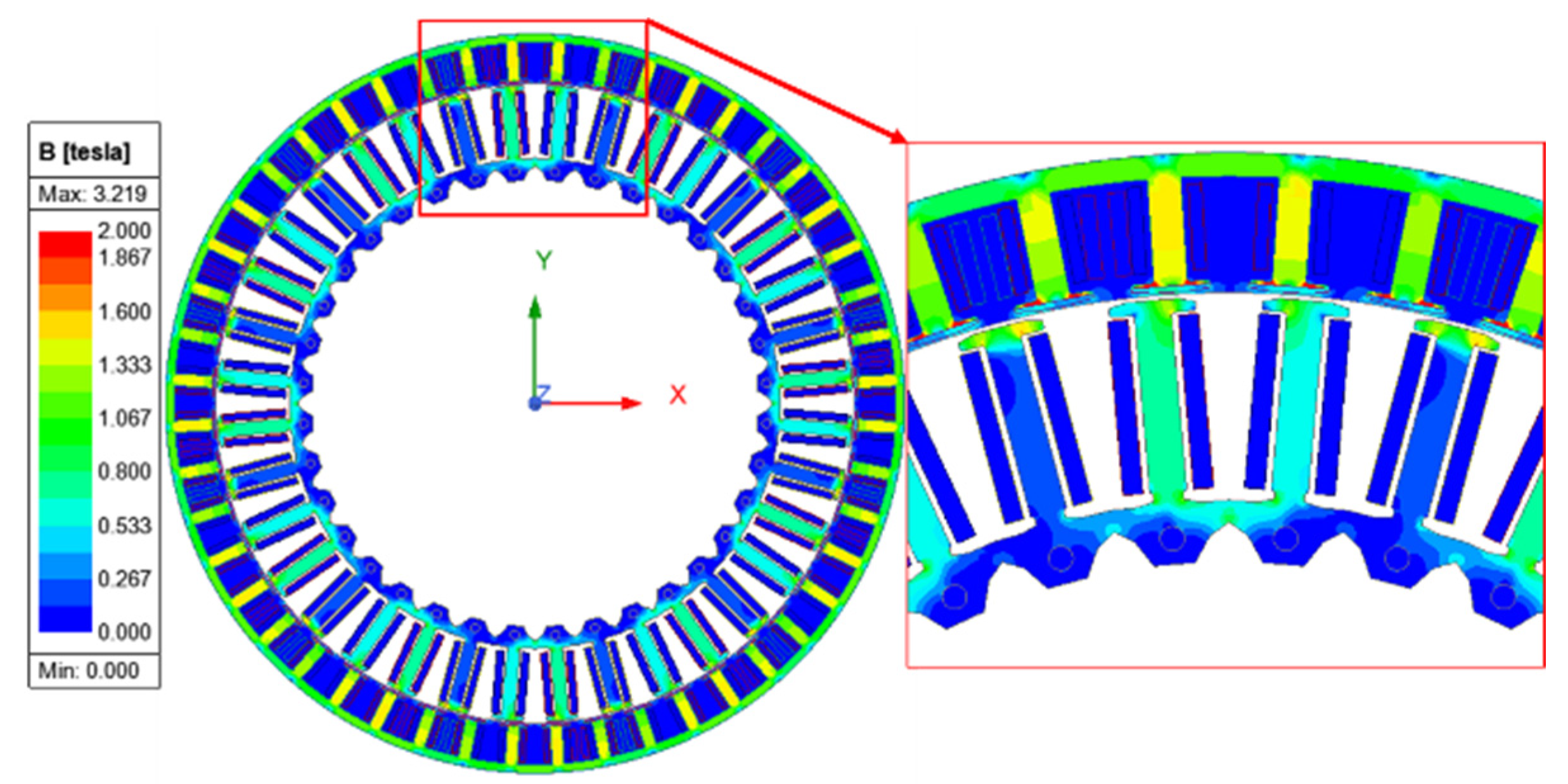
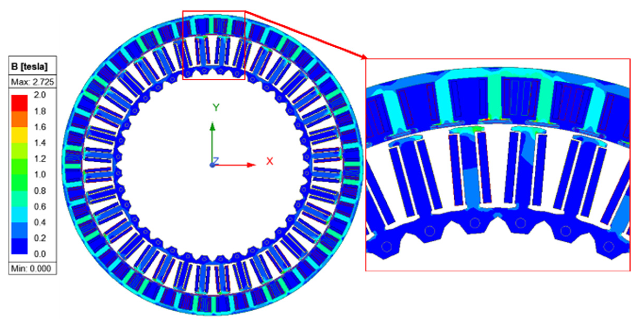
4.1. No-Load Performance

Figure 10a,b show the no-load voltage waveforms simulated at 46 rpm for the C-WRSM and the HB-WRSM. As for field winding excitation, a field current of 5.83 A is required to produce a no-load voltage of approximately 10.2 Vrms. In the case of the HB-WRSM with PM excitation only, the same voltage level is achieved, as shown in Figure 10b.

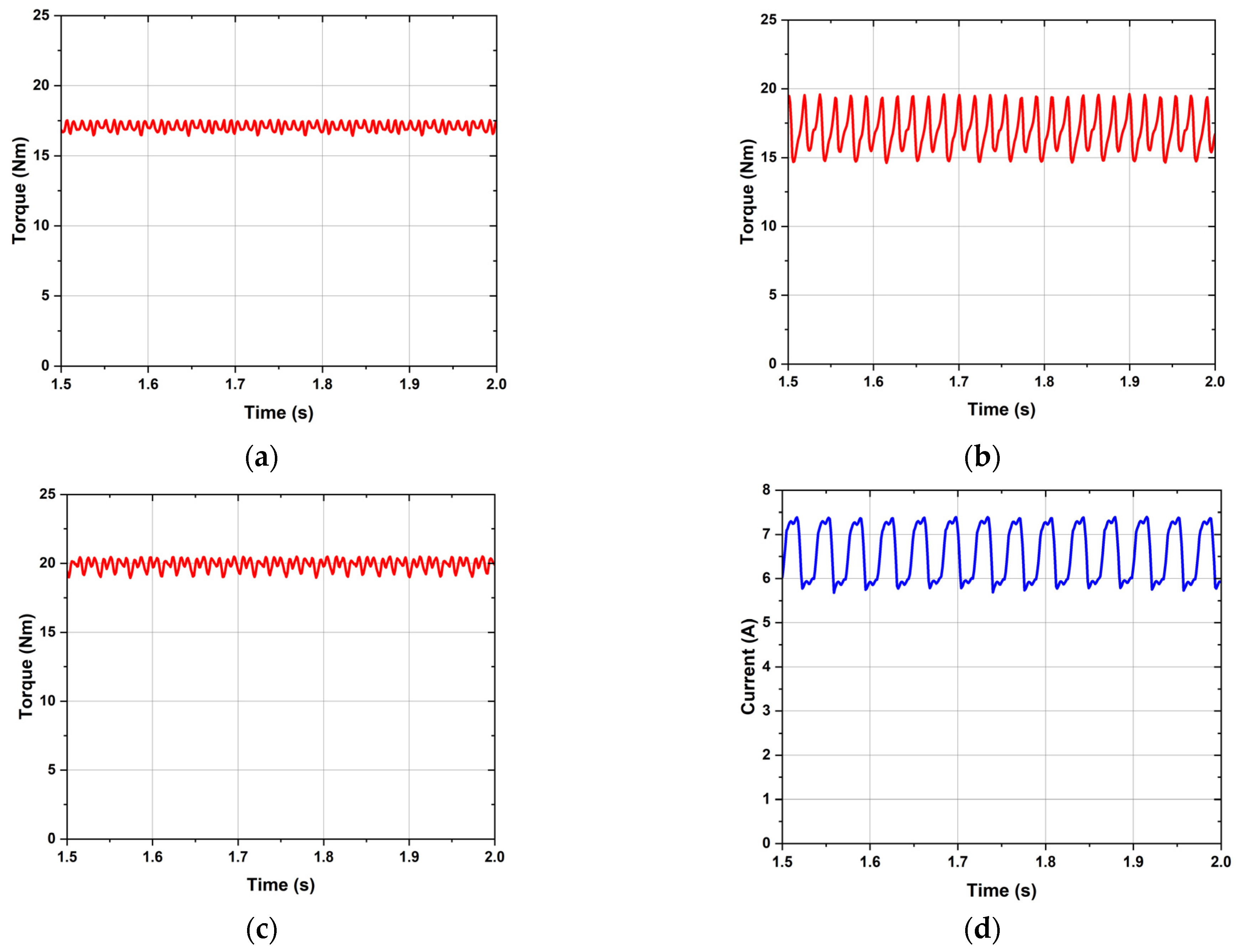
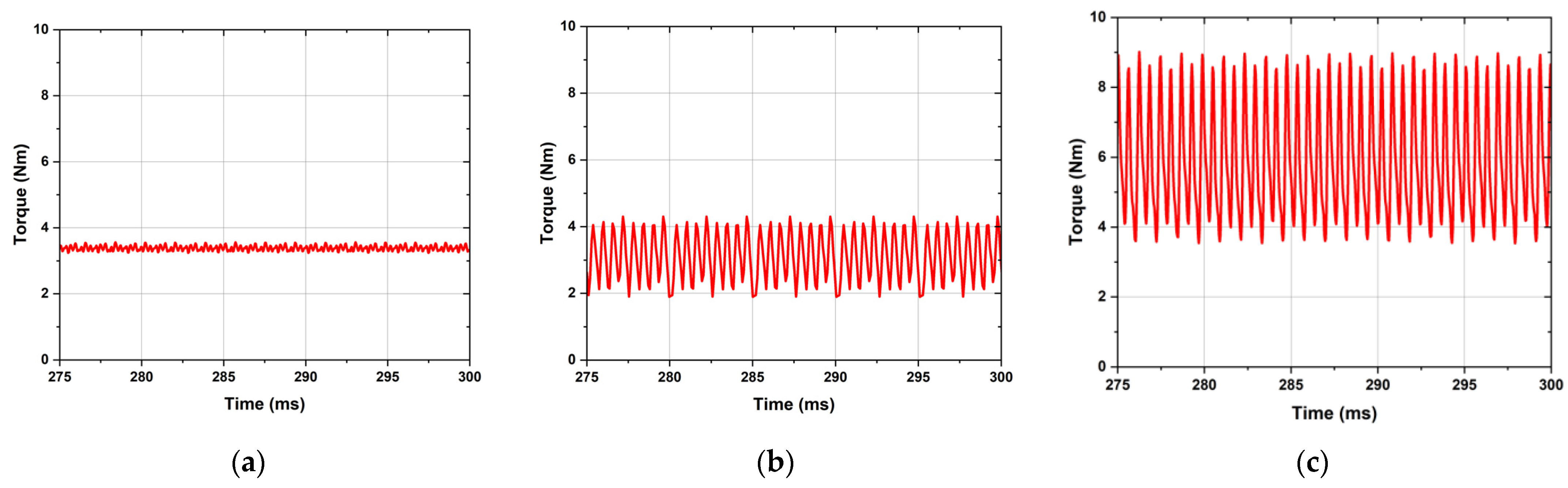
4.2. Washing Mode Performance

Figure 11a–c present the simulated torque waveforms for the C-WRSM, BL-WRSM, and HB-WRSM, respectively. In the C-WRSM, the torque waveform exhibits a reduced torque ripple due to the minimal impact of the tooth harmonic fields. In contrast, the torque waveform of the BL-WRSM shows a significant ripple, largely attributed to the current ripple in the rectified field current supplied by the harmonic winding. The field winding currents generated in the HB-WRSM, as shown in Figure 11d, contribute to additional losses in both the windings and the machine’s core.
To mitigate torque ripple and losses in the BL-WRSM, magnets are added to the rotor pole faces. This modification reduces the dependence on harmonic excitation, resulting in a lower torque ripple and reduced copper losses during the washing mode. The efficiency of the HB-WRSM during the washing mode increases from 35.35% to 50.02%, and the average torque reaches the highest value of the three designs.
Figure 12a shows that the flux density of the HB-WRSM in wash mode remains below 1.5 T, which is an acceptable level for most magnetic core regions. Figure 12b shows the mesh plot of the HB-WRSM. The mesh settings are the same for the other models.

4.3. Dry-Mode Performance

Figure 13a–c show the simulation torque waveforms in drying mode at 1370 rpm for the C-WRSM, BL-WRSM, and HB-WRSM, respectively.
As can be seen in the figures, the torque waveform of the C-WRSM in drying mode meets the average torque requirements, with excellent torque ripple performance. However, the torque waveform of the BL-WRSM in Figure 13b shows significant torque ripple due to the field current, similar to that in Figure 11d. As shown in Table 3, the torque ripple further increases at higher speeds due to the interaction between the fundamental magnetic field and the field current.
When the HB-WRSM operates in dry mode at 1370 rpm, the electromagnetic induction level increases, resulting in a higher rotor current and a corresponding increase in copper losses. The additional copper loss, amounting to 254.5 W, significantly reduces the machine’s efficiency to 67.7%, as shown in Table 3.
Figure 14 shows the flux contour plot of the HB-WRSM in dry mode, revealing elevated saturation levels in the rotor tooth and pole shoe areas. This saturation is attributed to the combined fluxes generated by both the rotor magnets and harmonic excitation. Although the average torque of the HB-WRSM is approx. 60 to 80% higher than the other two designs, the required output torque in dry mode is below 5 Nm, a level that can be achieved by magnet torque only. As a result, the HB-WRSM operates in dry mode as a PMSM without harmonic excitation by utilizing the centrifugal switch in Figure 13 that disconnects the harmonic winding from the field winding.

4.4. Performance Comparison

The average output torque and torque ripple for each topology are compared in Table 3. The HB-WRSM topology demonstrates improved torque in both the washing and drying modes. However, a notable increase in torque ripple is also observed, particularly during the drying mode. To address this issue, a fourth operational mode, referred to as the PMSM mode, will be introduced in the machine.

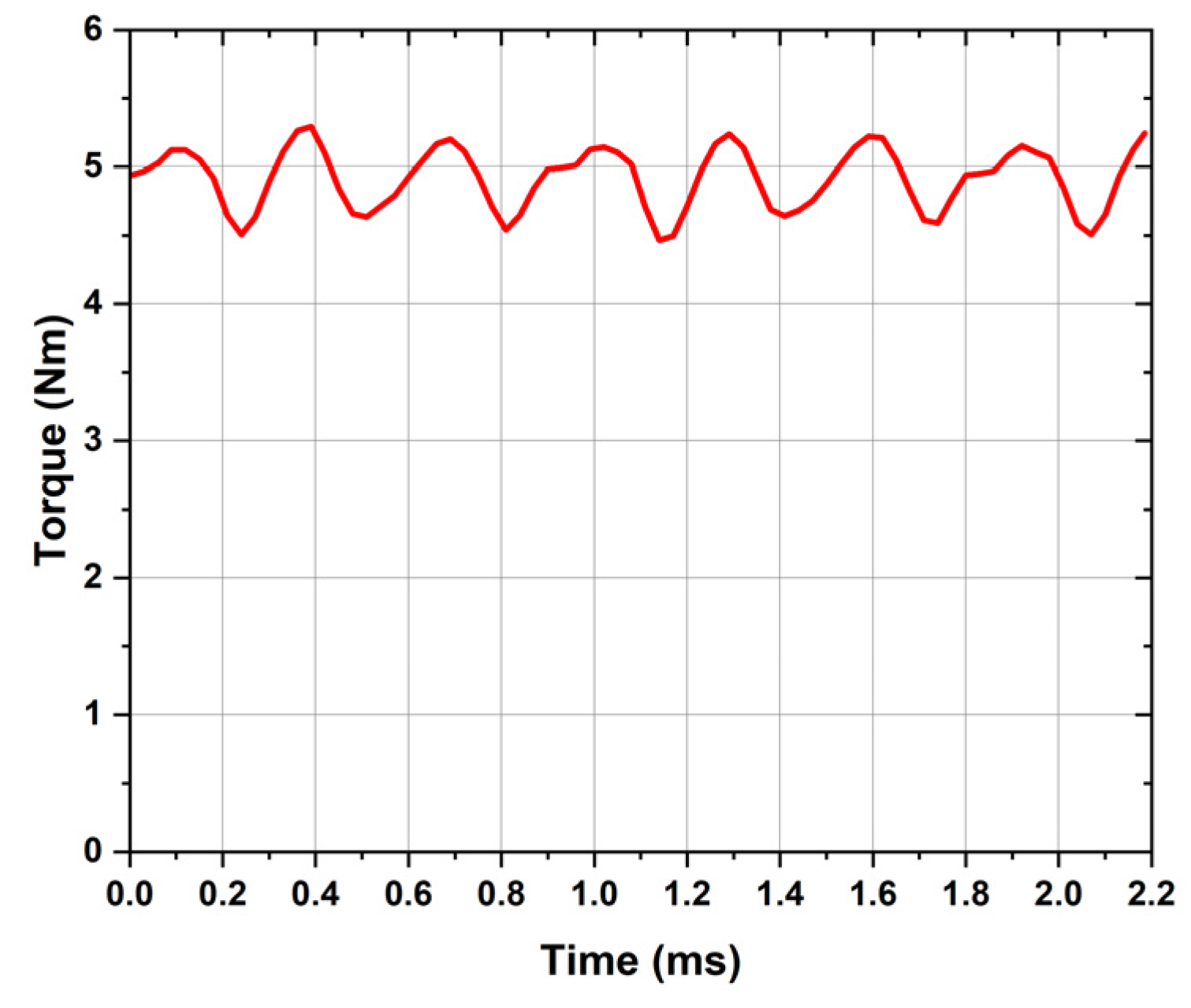
5. PMSM Operation Mode

To mitigate the high torque ripple observed in the HB-WRSM in dry mode, a centrifugal switch is introduced into the machine’s main electrical circuit, as shown in Figure 9. This switch allows the harmonic windings to be isolated from the main field windings, effectively de-energizing the rotor windings. This switch is activated when the washing machine is switched from a low-speed washing mode to a high-speed dry mode at 1370 rpm. When the machine switches to dry mode, the switch disconnects the windings, and the PMs embedded in the rotor poles solely generate rotor flux. In this configuration, the machine operates as a PMSM.
In this section, we present the results obtained for the HB-WRSM topology when operating in PMSM mode only at 1370 rpm. Figure 15 shows the flux contour plot of the HB-WRSM operating as a PMSM in dry mode, with lower saturation levels in the rotor tooth and pole shoe regions compared to Figure 14. The observed torque in dry mode is shown in Figure 16. The torque ripple is significantly reduced to 20.24%, compared to 91.24% for the HB-WRSM configuration. Therefore, the machine achieves optimal performance in PMSM mode during the drying phase.
The average torque of the proposed HB-WRSM in PMSM mode is reduced by 10%, yet it remains significantly higher than the two conventional designs, exceeding the C-WRSM and BL-WRSM by 46% and 62%, respectively. In addition, the efficiency of the proposed machine configuration is greatly enhanced, increasing from 67.68% to 92.48%, largely due to the reduced losses in the rotor windings and the machine’s core.
Table 4 provides a detailed comparison of performance metrics across all machine topologies. The overall performance of the proposed HB-WRSM with PMSM mode enabled outperforms the conventional WRSMs in all key metrics, including average torque, torque ripple, and efficiency.

6. Conclusions

This research introduced a novel HB-WRSM topology designed to deliver optimal performance at two distinct operating speeds for washing machines: a low-speed washing mode and high-speed drying mode. This study evaluated whether the HB-WRSM outperforms the C-WRSM and BL-WRSM at both operating points. To minimize torque ripple and copper losses, the HB-WRSM can function as a PMSM mode during drying operation. To achieve this, the HB-WRSM was redesigned to operate as a hybrid brushless system when a centrifugal switch is closed and transition to a PM synchronous machine when the switch is open.
One of the key advantages of the proposed HB-WRSM is its use of an inherent sub-harmonic magnetic field as an excitation source, which allows for reduced permanent magnet content, while increasing excitation levels at low speeds to achieve the necessary high torque. In drying mode, the rotor windings are disconnected via the centrifugal switch, eliminating copper losses, with permanent magnets providing sufficient excitation to achieve the required low torque.
Future research will focus on reducing torque ripple and losses through optimized or novel design strategies employing advanced techniques. Cost optimization may also be explored by incorporating a consequent-pole rotor configuration. Although transient phenomena—such as torque and current fluctuations during speed transitions—are critical to the overall performance, they have not yet been thoroughly investigated. Future work will therefore include detailed transient analyses and a comprehensive optimization across all the considered cases to enhance efficiency and dynamic performance.

Author Contributions

Conceptualization, S.A., Q.A. and G.J.S.; methodology, S.A.; software, S.A. and K.K.; validation, S.A., Q.A. and K.K.; formal analysis, S.A.; investigation, S.A. and K.K.; writing—original draft preparation, S.A. and Q.A.; writing—review and editing, G.J.S. and G.C.; supervision, Q.A., G.J.S. and G.C.; project administration, G.C.; funding acquisition, G.C. All authors have read and agreed to the published version of the manuscript.

Funding

This work was supported by an Inha University Research Grant.

Data Availability Statement

The original contributions presented in this study are included in the article; further inquiries can be directed to the corresponding author.

Acknowledgments

During the preparation of this manuscript/study, the authors used ChatGPT (GPT-4-turbo version) for the purposes of grammatical proofreading. The authors have reviewed and edited the output and take full responsibility for the content of this publication. The AI-powered proofreading tool was used to identify typos and grammatical errors, and explanations were requested for the corrections provided.

Conflicts of Interest

The authors declare no conflicts of interest.

References

  1. Du, Z.S.; Lipo, T.A. Cost-Effective High Torque Density Bi-Magnet Machines Utilizing Rare Earth and Ferrite Permanent Magnets. IEEE Trans. Energy Convers. 2020, 35, 1577–1584. [Google Scholar] [CrossRef]
  2. Cheramin, M.; Saha, A.K.; Cheng, J.; Paul, S.K.; Jin, H. Resilient NdFeB magnet recycling under the impacts of the COVID-19 pandemic: Stochastic programming and Benders decomposition. Transp. Res. Part E Logist. Transp. Rev. 2021, 155, 102505. [Google Scholar] [CrossRef]
  3. Kaya, E.E.; Kaya, O.; Stopic, S.; Gürmen, S.; Friedrich, B. NdFeB Magnets Recycling Process: An Alternative Method to Produce Mixed Rare Earth Oxide from Scrap NdFeB Magnets. Metals 2021, 11, 716. [Google Scholar] [CrossRef]
  4. Chakraborty, C.; Rao, Y.T.; Bhattacherjee, H. Brushless induction excited synchronous motor (BinSyM): A new motor for high power applications. In Proceedings of the 2016 IEEE 7th Power India International Conference (PIICON), Bikaner, India, 25–27 November 2016; pp. 1–6. [Google Scholar] [CrossRef]
  5. Yao, F.; An, Q.; Sun, L.; Lipo, T.A. Performance Investigation of a Brushless Synchronous Machine with Additional Harmonic Field Windings. IEEE Trans. Ind. Electron. 2016, 63, 6756–6766. [Google Scholar] [CrossRef]
  6. Chen, H.; Tang, J.; Liu, Y.; Jiang, B.; Boscaglia, L. Electromagnetic Performance Investigation of a Brushless Electrically Excited Synchronous Machine for Long-Distance Heavy-Duty Electric Vehicles. IEEE Trans. Transp. Electrific. 2025, 11, 225–235. [Google Scholar] [CrossRef]
  7. Hussain, A.; Atiq, S.; Kwon, B. Consequent-Pole Hybrid Brushless Wound-Rotor Synchronous Machine. IEEE Trans. Magn. 2018, 54, 8206205. [Google Scholar] [CrossRef]
  8. Mondal, A.K.; Basak, S.; Chakraborty, C. An Optimal Excitation Control Technique for Brushless Induction Excited Synchronous Motor (BINSYM). IEEE Trans. Ind. Electron. 2025, 72, 111–121. [Google Scholar] [CrossRef]
  9. Sirewal, G.J.; Ayub, M.; Atiq, S.; Kwon, B.-I. Analysis of a Brushless Wound Rotor Synchronous Machine Employing a Stator Harmonic Winding. IEEE Access 2020, 8, 151392–151402. [Google Scholar] [CrossRef]
  10. Yao, F.; An, Q.; Gao, X.; Sun, L.; Lipo, T.A. Principle of Operation and Performance of a Synchronous Machine Employing a New Harmonic Excitation Scheme. IEEE Trans. Ind. Appl. 2015, 51, 3890–3898. [Google Scholar] [CrossRef]
  11. Jiang, B.; Tang, J.; Liu, Y. Extended-Kalman-Filter-Based Field Current Estimation for Brushless Electrically Excited Synchronous Machines Using Stator Current Measurements. IEEE Trans. Transp. Electrific. 2025, 11, 5042–5054. [Google Scholar] [CrossRef]
  12. Pallantla, M.; Kumar, P. A Line-Commutated Thyristor Bridge Emulated Rotating Power Electronic Converter (LCTEPC) with Mode-Switching Algorithm for Brushless Exciter Applications. In Proceedings of the 2025 IEEE Texas Power and Energy Conference (TPEC), College Station, TX, USA, 10–11 February 2025; pp. 1–6. [Google Scholar] [CrossRef]
  13. Ali, Q.; Atiq, S.; Lipo, T.A.; Kwon, B. PM Assisted, Brushless Wound Rotor Synchronous Machine. J. Magn. 2016, 21, 399–404. [Google Scholar] [CrossRef]
  14. Zhang, Z.; Shi, L.; Yang, L.; Li, W.; Ma, J.; Li, R.; Yin, Z.; Du, G. Identification Methods for Rotating Diode Rectifier Open Circuit Failures Without Rotor Position Information in Brushless Exciter Systems of Wound Field Synchronous Machines. IEEE Trans. Ind. Electron. 2025; in press. [Google Scholar] [CrossRef]
  15. Sirewal, G.J.; Lipo, T.A.; Kwon, B. Torque ripple reduction in brushless wound rotor synchronous machine by two-phase excitation winding. Int. J. Appl. Electromagn. Mech. 2019, 59, 765–773. [Google Scholar] [CrossRef]
  16. Jawad, G.; Ali, Q.; Lipo, T.A.; Kwon, B.-I. Novel Brushless Wound Rotor Synchronous Machine With Zero-Sequence Third-Harmonic Field Excitation. IEEE Trans. Magn. 2016, 52, 8106104. [Google Scholar] [CrossRef]
  17. Lee, J.; Lee, D.; Nam, K. Inductance Measurement and Parameter Identification for a Permanent Magnet Synchronous Motor Drive. IEEE Trans. Ind. Electron. 2010, 57, 2520–2528. [Google Scholar] [CrossRef]
  18. Nonaka, S.; Kawaguchi, T. Excitation scheme of brushless self-excited-type three-phase synchronous machine. IEEE Trans. Ind. Appl. 1992, 28, 1322–1329. [Google Scholar] [CrossRef]
  19. Kano, Y. Design optimization of brushless synchronous machines with wound-field excitation for hybrid electric vehicles. In Proceedings of the 2015 IEEE Energy Conversion Congress and Exposition (ECCE), Montreal, QC, Canada, 20–24 September 2015; pp. 2769–2775. [Google Scholar] [CrossRef]
  20. Park, H.-J.; Lim, M.-S. Design of High-Power Density and High Efficiency Wound-Field Synchronous Motor for Electric Vehicle Traction. IEEE Access 2019, 7, 46677–46685. [Google Scholar] [CrossRef]
  21. Li, J.; Li, Z.; Zhang, J.; Zhao, S.; Cheng, F.; Qian, C.; Hu, X.; Zhou, G. Automated Monitoring of the Uniform Demagnetization Faults in Permanent-Magnet Synchronous Motors: Practical Methods and Challenges. Sustainability 2023, 15, 16326. [Google Scholar] [CrossRef]
  22. Dorrell, D.G. Are wound-rotor synchronous motors suitable for use in high efficiency torque-dense automotive drives? In Proceedings of the IECON 2012—38th Annual Conference on IEEE Industrial Electronics Society, Montreal, QC, Canada, 25–28 October 2012; pp. 4880–4885. [Google Scholar] [CrossRef]
  23. Yao, F.; Sun, D.; Sun, L.; Lipo, T.A. Dual Third Harmonic-Current Excitation Principle of a Brushless Synchronous Machine Based on Double Three-Phase Armature Windings. In Proceedings of the 2019 22nd International Conference on Electrical Machines and Systems (ICEMS), Harbin, China, 11–14 August 2019; pp. 1–4. [Google Scholar] [CrossRef]
  24. Salo, M.; Tiitinen, J. Vector Controlled PWM Current-Source-Inverter-Fed Permanent Magnet Synchronous Motor Drive with a Low-Pass Filter. IEEE Trans. Ind. Appl. 2002, 38, 1392–1400. [Google Scholar] [CrossRef]
  25. Bukhari, S.S.H.; Ahmad, H.; Sirewal, G.J.; Ro, J.-S. Simplified Brushless Wound Field Synchronous Machine Topology Based on a Three-Phase Rectifier. IEEE Access 2021, 9, 8637–8648. [Google Scholar] [CrossRef]
  26. Hussain, A.; Kwon, B. Novel single inverter fed brushless wound rotor synchronous machine. In Proceedings of the 2017 IEEE International Magnetics Conference (INTERMAG), Dublin, Ireland, 24–28 April 2017. [Google Scholar] [CrossRef]
  27. Gieras, J.F.; Wang, C.; Kamper, M.J. Axial Flux Permanent Magnet Brushless Machines; Springer: Berlin/Heidelberg, Germany, 2008. [Google Scholar] [CrossRef]
  28. Salminen, P.; Pyrhönen, J.; Nerg, J. Design Aspects of High-Speed Synchronous Machines. IEEE Trans. Ind. Electron. 2006, 53, 1419–1426. [Google Scholar] [CrossRef]
  29. Tang, L.; Rahman, M.F.; Zhong, L.; Lim, K.W. A Novel Direct Torque Control for Interior Permanent-Magnet Synchronous Machine Drive with Low Ripple in Torque and Flux—A Speed-Sensorless Approach. IEEE Trans. Ind. Electron. 2004, 51, 759–767. [Google Scholar] [CrossRef]
  30. Xu, L.; Ruxi, S.; Zhao, L. A New Rotor Position Detection Method for Permanent Magnet Synchronous Machine Drive at Zero and Very Low Speed. IEEE Trans. Ind. Electron. 2009, 56, 2017–2023. [Google Scholar] [CrossRef]
  31. Direct Drive Motor Specification. Fisher & Paykel Technologies. Available online: https://www.fisherpaykeltechnologies.com/technology/direct-drive-motors (accessed on 9 March 2025).
  32. In Geun Ahn. Stator of Motor and Washing Apparatus Having the Same. Available online: https://patents.google.com/patent/US20110016929 (accessed on 9 March 2025).
  33. Scuiller, F. General, Compact and Easy-to-Compute Winding Factor Formulation. IET Electr. Power Appl. 2020, 14, 1430–1437. [Google Scholar] [CrossRef]
  34. Ahmed, S.; Siddiqi, M.R.; Ali, Q.; Yazdan, T.; Hussain, A.; Hur, J. Brushless Wound Rotor Synchronous Machine Topology Using Concentrated Winding for Dual Speed Applications. IEEE Access 2023, 11, 119560–119567. [Google Scholar] [CrossRef]
Figure 1. Dual inverter topology: (a) schematic diagram; (b) dual-mode operation of BL-WRSM.
Machines 13 00342 g001
Figure 2. Uncontrolled three-phase rectifier-based BL-WRSM.
Machines 13 00342 g002
Figure 3. Typical washing machine requirements.
Machines 13 00342 g003
Figure 4. Stator and rotor structure of 4 commercial washing machines: (a) Samsung 36-slot/48-pole external rotor model; (b) LG 36-slot/48-pole external rotor model; (c) Whirlpool 36-slot/48-pole external rotor model; (d) Whirlpool Maytag 36-slot/48-pole external rotor model.
Machines 13 00342 g004
Figure 5. Structure of the 3 baseline machines: (a) C-WRSM; (b) BL-WRSM; (c) HB-WRSM.
Machines 13 00342 g005
Figure 6. Working principle of BL-WRSM.
Machines 13 00342 g006
Figure 7. Stator winding configuration.
Machines 13 00342 g007
Figure 8. Three-phase MMF harmonic spectrum.
Machines 13 00342 g008
Figure 9. HB-WRSM rotor circuit.
Machines 13 00342 g009
Figure 10. No-load back-emf voltage waveforms: (a) C-WRSM; (b) HB-WRSM with PM excitation only.
Machines 13 00342 g010
Figure 11. Torque waveforms: (a) C-WRSM in washing mode; (b) BL-WRSM in washing mode; (c) HB-WRSM in washing mode; (d) field current waveform of HB-WRSM.
Machines 13 00342 g011
Figure 12. HB-WRSM (a) flux density contour in washing mode, (b) mesh plot.
Machines 13 00342 g012
Figure 13. Torque waveforms in dry mode: (a) C-WRSM; (b) BL-WRSM; (c) HB-WRSM.
Machines 13 00342 g013
Figure 14. HB-WRSM flux density contour in dry mode.
Machines 13 00342 g014
Figure 15. PMSM flux density contour in dry mode.
Machines 13 00342 g015
Figure 16. Torque waveform in dry mode during PMSM mode.
Machines 13 00342 g016
Table 1. MMF components and their rotating speeds.
Fundamental
Frequency
Harmonic OrderNumber of PolesSynchronous Speed
60 Hz0.524150 r/min
60 Hz148300 r/min
Table 2. Key parameters of the baseline machines.
ParameterUnitC-WRSMBL-WRSMHB-WRSM
Value
Number of slots-363636
Field winding poles-484848
Harmonic winding poles--2424
Stator OD/IDmm265/186265/186265/186
Rotor OD/IDmm308/267308/267308/267
Air-gap lengthmm111
Axial lengthmm242424
Washing mode speedr/min464646
Drying mode speedr/min137013701370
Frequency in washing modeHz18.418.418.4
Frequency in drying modeHz548548548
Number of magnets---48
Magnet material---NdFe30
Table 3. Comparison of average torque and torque ripple.
Fundamental FrequencyWashing ModeDry ModeWashing ModeDry Mode
Torque [Nm]Torque Ripple [%]
C-WRSM17.143.375.228.81
BL-WRSM16.393.0425.1239.77
HB-WRSM19.415.467.8693.0
Table 4. Performance comparison of the three machine topologies.
ParameterC-WRSMBL-WRSMHB-WRSMPMSM Mode
WashDryWashDryWashDryDry
Average torque [Nm]17.143.3716.343.0319.415.474.91
Torque ripple [%]5.228.8125.1239.777.8693.020.0
Harmonic current [A]005.703.631.7810.860
Field current [A]5.834.166.264.871.8513.640
Output power [W]82.54484.2578.90435.8093.46783.87704.13
Core loss [W]1.6218.721.4511.591.1786.3223.76
Rotor copper loss [W]41.1220.9355.4831.994.87254.460
Stator copper loss [W]87.3333.4887.3333.4887.3333.4833.48
Efficiency [%]38.8286.8735.3584.9750.0267.6892.48
Disclaimer/Publisher’s Note: The statements, opinions and data contained in all publications are solely those of the individual author(s) and contributor(s) and not of MDPI and/or the editor(s). MDPI and/or the editor(s) disclaim responsibility for any injury to people or property resulting from any ideas, methods, instructions or products referred to in the content.

