Contactless Mechanical Components: Gears, Torque Limiters and Bearings

 , ,
, ,
Abstract
:1. Introduction
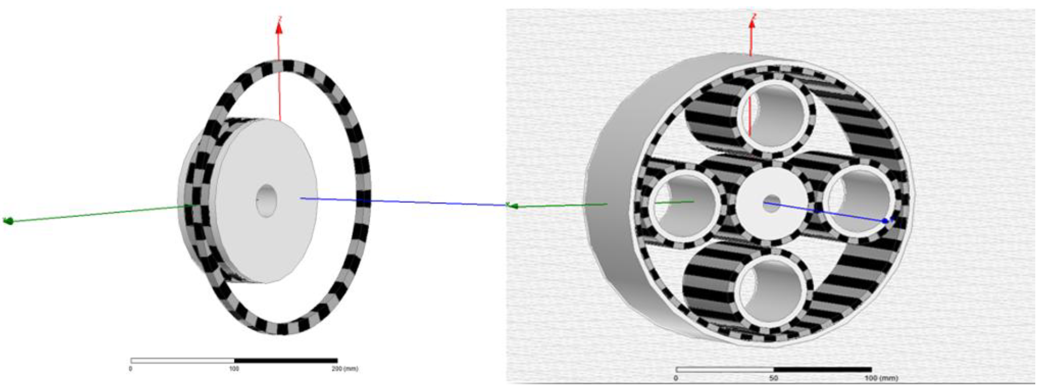
2. Magnetic Gears
2.1. Spur Gears and Planetary Gears


| Specification | Magnetic Planetary Gear |
|---|---|
| Reduction ratio (i) | 4 |
| Max output torque (Nm) | 26 |
| Torque Density (kNm/m3) | 24 |
| Max input speed (rpm) | 3000 |
| Max Efficiency (%) | 95 |
| Mass (kg) | 3 |
| Outer Diameter × Length (mm × mm) | 166 × 52 |
| Max Operational Temp. (°C) | 80 |
| Min Operational Temp. (°C) | −40 |
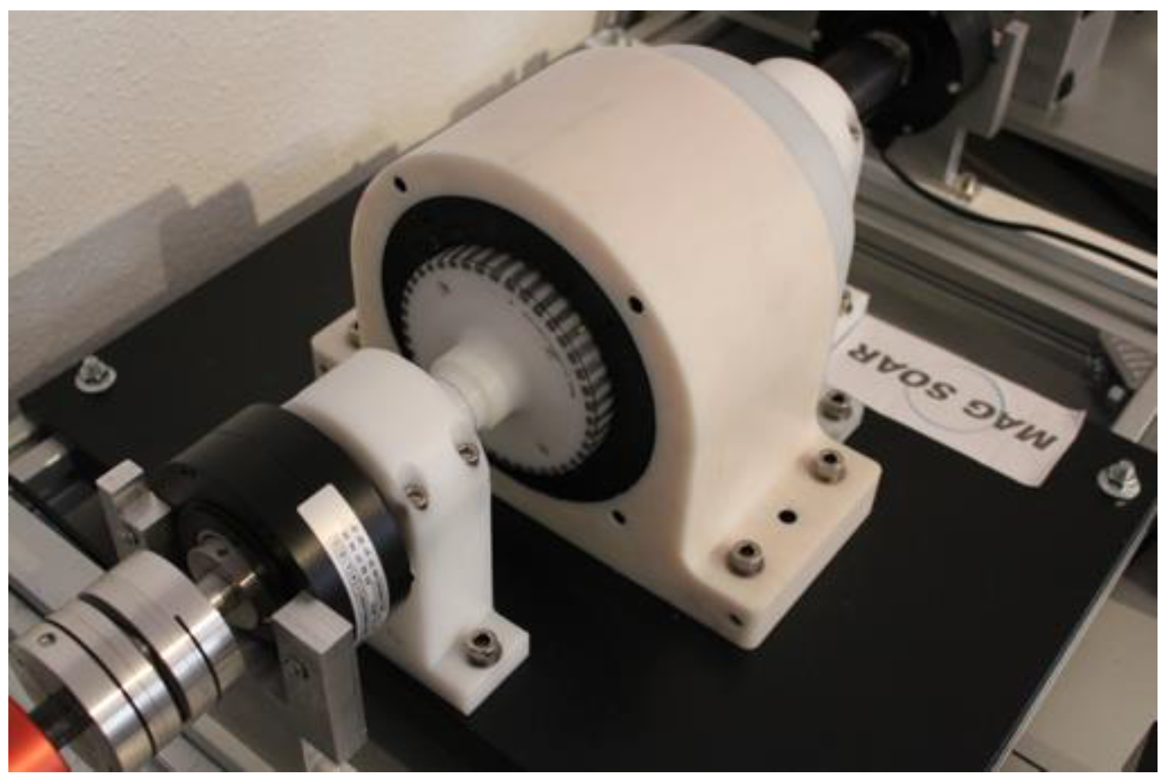
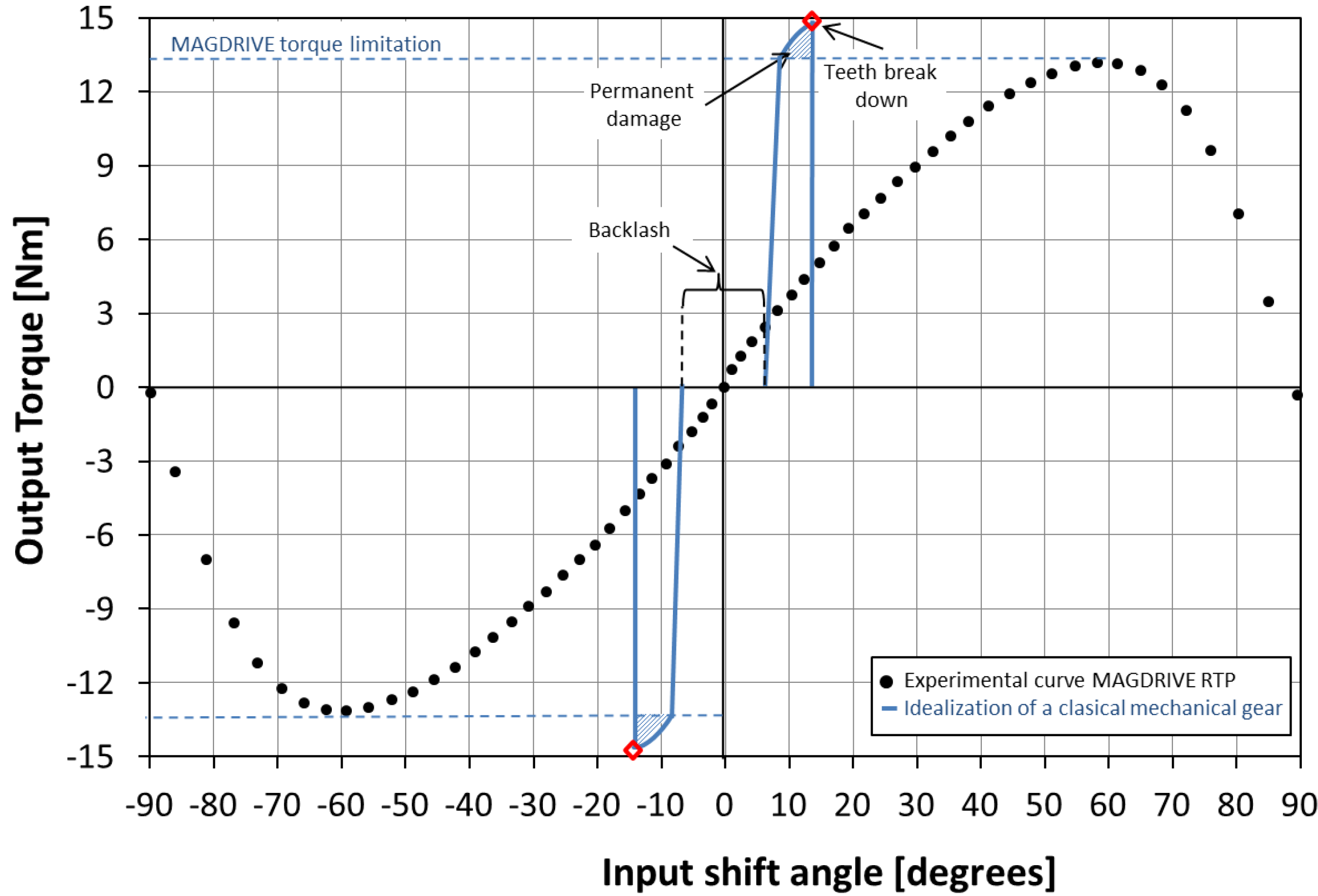
2.2. Magnetic Harmonic Drives—Magdrives

| Specification | MAGDRIVE | ||
|---|---|---|---|
| Room Temp. Prototype | Cryogenic Prototype | MAG SOAR MD-101 | |
| Magneto-Mechanical Combination | Magnetic Teeth + Ball Bearing | Magnetic Teeth + Superconducting Magnetic Bearing (ZERO FRICTION) | Magnetic Teeth + Dry Lubricated Ball Bearing |
| Reduction ratio (i) | 21 | 21 | 101 |
| Max output torque (Nm) | 15 | 4 | 45 |
| Torque Density (kNm/m3) | 10.7 | 2.5 | 71 |
| Max input speed (rpm) | 500 | 3000 | 4500 |
| Max Efficiency (%) | 95 | − | 95 |
| Accuracy (arcmin) | ±3 | ±1 | ±0.1 |
| Mass (kg) | 5 | 8 | 2 |
| Envelope: Diameter × Length (mm × mm) | 120 × 110 | 120 × 400 | 100 × 80 |
| Max. Operational Temp.(°C) | 80 | −180 | +120 |
| Min Operational Temp. (°C) | −40 | −260 | −196 |
| Input cycles lifetime | >4 millions | >1.5 millions | >2 millions |

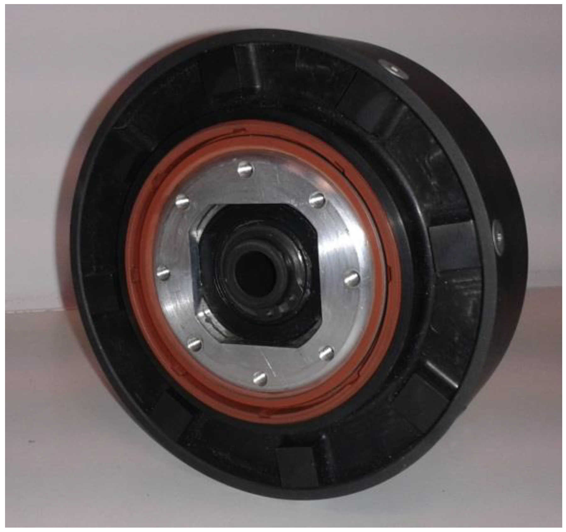
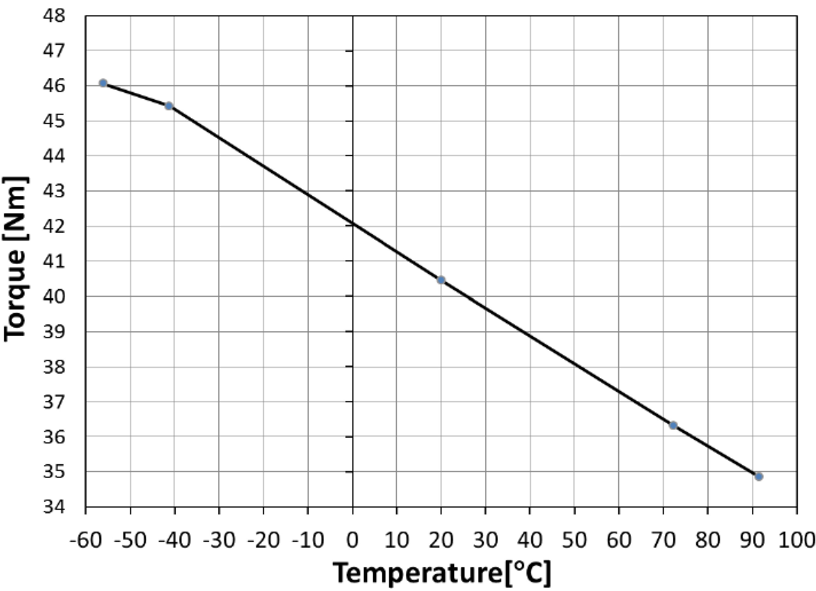
3. Magnetic Torque Limiters

| Specification | MAGSOAR TL-40 |
|---|---|
| Reduction ratio (i) | 1 |
| Max output torque (Nm) | 40 |
| Torque Density (kNm/m3) | 106 |
| Max input speed (rpm) | 15,000 |
| Max Efficiency (%) | 99.5 |
| Mass (kg) | 2 |
| Envelope: Outer Diameter × Length (mm × mm) | 112 × 38 |
| Max Operational Temp. (°C) | 90 |
| Min Operational Temp. (°C) | −55 |
| Operation hours | >200 h |
| Torque limitations activations | >300 |

4. Superconducting Magnetic Bearings

| Specification | MAG SOAR SMBs |
|---|---|
| Axial maximum load (N) | up to 1500 N |
| Axial stiffness (N/mm) | 150 |
| Radial stiffness (N/mm) | 50 |
| Maximum speed (rpm) | 25,000 |
| Efficiency (%) | 99.7 |
| Max Operational Temp. (°C) | −190 |
| Min Operational Temp. (°C) | −270 |
| Operation hours | >1500 h |
5. Conclusions
Acknowledgments
Author Contributions
Conflicts of Interest
References
- Ostrovskaya, Y.L.; Yukhno, T.; Gamulya, G.; Vvedenskij, Y.V.; Kuleba, V. Low Temperature Tribology at the B. Verkin Institute for Low Temperature Physics & Engineering (historical review). Tribol. Int. 2001, 34, 265–276. [Google Scholar] [CrossRef]
- Trautmann, A.; Siviour, C.R.; Walley, S.M.; Field, J.E. Lubrication of polycarbonate at cryogenic temperatures in the split Hopkinson pressure bar. Int. J. Impact Eng. 2005, 31, 523–544. [Google Scholar] [CrossRef]
- Theiler, G.; Gradt, T.; Klein, P. Friction and wear of PTFE composites at cryogenic temperatures. Tribol. Int. 2002, 35, 449–458. [Google Scholar] [CrossRef]
- Jian, L.; Chau, K.T. A Coaxial Magnetic Gear With Halbach Permanent-Magnet Arrays. IEEE Trans. Energy Convers. 2010, 25, 319–328. [Google Scholar] [CrossRef]
- Jørgensen, F.T.; Andersen, T.O.; Rasmussen, P.O. The Cycloid Permanent Magnetic Gear. IEEE Trans. Ind. Appl. 2008, 44, 1659–1665. [Google Scholar] [CrossRef]
- Valiente-Blanco, I.; Diez-Jimenez, E. Characterization and Improvement of Axial and Radial Stiffness of Contactless Thrust Superconducting Magnetic Bearings. Tribol. Lett. 2014, 54, 213–220. [Google Scholar] [CrossRef]
- Cristache, C.; Valiente-Blanco, I.; Diez-Jimenez, E.; Sanchez-Garcia-Casarrubios, A.J.; Perez-Diaz, J.L. Mechanical characterization of journal superconducting magnetic bearings: Stiffness, hysteresis and force relaxation. J. Phys. Conf. Ser. 2014, 507. [Google Scholar] [CrossRef]
- Perez-Diaz, J.L. Superconducting Noncontact Device for Precision Positioning in Cryogenic Environments. IEEE ASME Trans. Mechatron. 2014, 19, 598–605. [Google Scholar] [CrossRef]
- Harmonic Drive AG Catalog. Available online: http://harmonicdrive.net/support/catalogs/ (accessed on 5 May 2014).
- Misgeld, B.; Gerlach-Hahn, K. Control of Adjustable Compliant Actuators. Machines 2014, 2, 134–157. [Google Scholar] [CrossRef]
- Bouheraoua, M.; Wang, J.; Atallah, K. Influence of Control Structures and Load Parameters on Performance of a Pseudo Direct Drive. Machines 2014, 2, 158–175. [Google Scholar] [CrossRef]
- KTR Catalog. Available online: http://www.ktr.com/en/index/service/876_productcatalog/catalog/productcatalog.htm (accessed on 5 May 2014).
- Bassani, R. Magnetoelastic Stability of Magnetic Axial Bearings. Tribol. Lett. 2012, 49, 397–401. [Google Scholar] [CrossRef]
- Power Consumption. J. Tribol. 1996, 118, 839–846.
- Di Puccio, F.; Bassani, R.; Ciulli, E.; Musolino, A.; Rizzo, R. Permanent magnet bearings: Analysis of plane and axisymmetric V-shaped element design. Prog. Electromagn. Res. M 2012, 26, 205–223. [Google Scholar] [CrossRef]
- Musolino, A.; Rizzo, R.; Tucci, M.; Matrosov, V.M. A New Passive Maglev System Based on Eddy Current Stabilization. IEEE Trans. Magn. 2009, 45, 984–987. [Google Scholar] [CrossRef]
- Filion, G.; Ruel, J.; Dubois, M. Reduced-Friction Passive Magnetic Bearing: Innovative Design and Novel Characterization Technique. Machines 2013, 1, 98–115. [Google Scholar] [CrossRef]
- Werfel, F.N.; Floegel-Delor, U.; Rothfeld, R.; Riedel, T.; Goebel, B.; Wippich, D.; Schirrmeister, P. Superconductor bearings, flywheels and transportation. Supercond. Sci. Technol. 2012, 25. [Google Scholar] [CrossRef]
- Navarro, R.; Elswijk, E.; Tromp, N.; Kragt, J.; Kroes, G.; Hanenburg, H.; de Haan, M.; Schuil, M.; Teuwen, M.; Janssen, H.; et al. Precision Mechanism for Optics in a Vacuum Cryogenic Environment. In Proceedings of International Conference on Space Optics, Rhodes, Greece, 4–8 October 2010; pp. 1–6.
- Weisensel, G.N.; McMasters, O.D.; Chave, G.R. Cryogenic magnetostrictive transducers and devices for commercial, military, and space applications. Proc. SPIE 1998, 3326, 459–470. [Google Scholar]
- Maillard, T.; Claeyssen, F.; LeLetty, R.; Sosnicki, O.; Pages, A.; Vazquez Carazo, A. Piezomechatronic-based systems in aircraft, space, and defense applications. Proc. SPIE 2009, 7331, 1–9. [Google Scholar]
- Iizuka, T.; Maeda, Y.; Aihara, K.; Fujita, H. A micro X-Y-θ conveyor by superconducting magnetic levitation. In Proceedings of IEEE Symposium on Emerging Technologies and Factory Automation, Tokyo, Japan, 6–10 Novemver 1994; pp. 62–67.
- Pérez-Díaz, J.L.; García-Prada, J.C.; Diez-Jimenez, E.; Valiente-Blanco, I.; Sander, B.; Timm, L.; Sánchez-García-Casarrubios, J.; Serrano, J.; Romera, F.; Argelaguet-Vilaseca, H.; et al. Non-contact linear slider for cryogenic environment. Mech. Mach. Theory 2012, 49, 308–314. [Google Scholar] [CrossRef]
- Serrano-tellez, J.; Romera-juarez, F.; González-de-maría, D.; Lamensans, M.; Argelaguet-Vilaseca, H.; Pérez-Díaz, J.L.; Sánchez-Casarrubios, J.; Díez-Jiménez, E.; Valiente-Blanco, I. Experience on a cryogenic linear mechanism based on superconducting levitation. Proc. SPIE 2012, 8450. [Google Scholar] [CrossRef]
- Morales, W.; Fusaro, R.; Kascak, A. Permanent Magnetic Bearing for Spacecraft Applications. Tribol. Trans. 2003, 46, 460–464. [Google Scholar] [CrossRef]
- Valiente-Blanco, I.; Diez-Jimenez, E.; Perez-Diaz, J.L. Alignment effect between a magnet over a superconductor cylinder in the Meissner state. J. Appl. Phys. 2011, 109. [Google Scholar] [CrossRef]
- Diez-Jimenez, E.; Perez-Diaz, J.L. Foundations of Meissner Superconductor Magnet Mechanisms Engineering. In Superconductivity—Theory and Applications; Luiz, A.M., Ed.; InTech: Rijeka, Croatia, 2011; pp. 153–172. [Google Scholar]
- Diez-Jimenez, E.; Perez-Diaz, J.L. Flip effect in the orientation of a magnet levitating over a superconducting torus in the Meissner state. Phys. C Supercond. 2011, 471, 8–11. [Google Scholar] [CrossRef]
- Diez-Jimenez, E.; Sander, B. Tailoring of the flip effect in the orientation of a magnet levitating over a superconducting torus: Geometrical dependencies. Phys. C Supercond. 2011, 471, 229–232. [Google Scholar] [CrossRef]
- Perez-Diaz, J.L.; Diez-Jimenez, E.; Valiente-Blanco, I.; Herrero-de-Vicente, J. Stable thrust on a finite-sized magnet above a Meissner superconducting torus. J. Appl. Phys. 2013, 113. [Google Scholar] [CrossRef]
- Diez-Jimenez, E.; Valiente-Blanco, I.; Perez-Diaz, J.L. Superconducting Sphere and Finite-Size Permanent Magnet: Force, Torque, and Alignment Effect Calculation. J. Supercond. Novel Magn. 2012, 26, 71–75. [Google Scholar] [CrossRef]
- Diez-Jimenez, E.; Perez-Diaz, J.L.; Garcia-Prada, J.C. Mechanical method for experimental determination of the first penetration field in high-temperature superconductors. IEEE Trans. Appl. Supercond. 2012, 22. [Google Scholar] [CrossRef]
- Diez-Jimenez, E.; Perez-Diaz, J.L.; Castejon, C. FEM Algorithm for Solving Superconducting Meissner Repulsion Forces. Int. Rev. Mech. Eng. 2010, 4, 673–675. [Google Scholar]
- Diez-Jimenez, E.; Perez-Diaz, J.L.; Garcia-Prada, J.C. Local model for magnet-superconductor mechanical interaction: Experimental verification. J. Appl. Phys. 2011, 109. [Google Scholar] [CrossRef]
- Qin, Y.; Hou, X. Influence of maglev force relaxation on the forces of bulk HTSC subjected to different lateral displacements above the NdFeB guideway. Phys. C Supercond. 2011, 471, 118–120. [Google Scholar] [CrossRef]
- Xia, Z.; Chen, Q.Y.; Ma, K.B.; McMichael, C.K.; Lamb, M.; Cooley, R.S.; Fowler, P.C.; Chu, W.K. Design of superconducting magnetic bearings with high levitating force for flywheel energy storage systems. IEEE Trans. Appl. Supercond. 1995, 5, 622–625. [Google Scholar] [CrossRef]
© 2014 by the authors; licensee MDPI, Basel, Switzerland. This article is an open access article distributed under the terms and conditions of the Creative Commons Attribution license (http://creativecommons.org/licenses/by/4.0/).
Share and Cite
Perez-Diaz, J.L.; Diez-Jimenez, E.; Valiente-Blanco, I.; Cristache, C.; Alvarez-Valenzuela, M.-A.; Sanchez-Garcia-Casarrubios, J. Contactless Mechanical Components: Gears, Torque Limiters and Bearings. Machines 2014, 2, 312-324. https://doi.org/10.3390/machines2040312
Perez-Diaz JL, Diez-Jimenez E, Valiente-Blanco I, Cristache C, Alvarez-Valenzuela M-A, Sanchez-Garcia-Casarrubios J. Contactless Mechanical Components: Gears, Torque Limiters and Bearings. Machines. 2014; 2(4):312-324. https://doi.org/10.3390/machines2040312
Chicago/Turabian StylePerez-Diaz, Jose Luis, Efren Diez-Jimenez, Ignacio Valiente-Blanco, Cristian Cristache, Marco-Antonio Alvarez-Valenzuela, and Juan Sanchez-Garcia-Casarrubios. 2014. "Contactless Mechanical Components: Gears, Torque Limiters and Bearings" Machines 2, no. 4: 312-324. https://doi.org/10.3390/machines2040312
APA StylePerez-Diaz, J. L., Diez-Jimenez, E., Valiente-Blanco, I., Cristache, C., Alvarez-Valenzuela, M.-A., & Sanchez-Garcia-Casarrubios, J. (2014). Contactless Mechanical Components: Gears, Torque Limiters and Bearings. Machines, 2(4), 312-324. https://doi.org/10.3390/machines2040312