1. Introduction
Battery chargers can either be installed at charging stations, known as off-board chargers, or mounted on electric vehicles (EVs), known as on-board chargers. Although off-board chargers offer high power transfer capability, their installation cost is substantially high. On the other hand, on-board battery chargers (OBCs) are cost-effective units that can be directly connected to the grid; however, their power transfer capability is restricted because of weight, space, and cost constraints. To alleviate the problems associated with OBCs and the lack of charging points, integrated OBCs have been the topic of a significant body of recent literature [
1]. The proposed charging topology integrates the drivetrain elements into the charging process, thus facilitating the deployment of fast three-phase charging [
2].
Various electric machines can be used in EVs, namely the induction motor (IM), permanent magnet synchronous machine (PMSM), and switched-reluctance motor (SRM) [
3]. IMs have been utilized in several Tesla Models (e.g., Model S, Model X, and Roadster). Meanwhile, the electric traction machine used in the Volkswagen e-Golf is a PMSM [
4]. Despite being cost effective and providing good traction performance [
5], practical employment of SRMs in commercial EVs is very limited due to the machine’s high torque ripple. It is worth mentioning that PMSMs have the highest efficiency among all other EV drivelines, both three-phase and multiphase configurations. The prime motivation to employ multiphase-based machines in EV applications, besides fault tolerance capability and decreased converter per phase current rating, is the higher degrees of freedom that ensure zero average torque production during the charging process [
6].
Performance wise, PM machines equipped with a fractional slot concentrated winding (FSCW) have shown promise in EV applications, as they correspond to a substantial improvement in torque/power densities [
7]. Among all possible winding layouts, e.g., the six-phase asymmetrical, six-phase symmetrical, dual three-phase layouts, the six-phase asymmetrical configuration gives better rotor loss index when compared to the dual three-phase one under both the propulsion and charging modes of operation owing to its superior MMF spectra [
2]. Recently, the optimal design of FSCW-based PM machines has been investigated in the literature [
8,
9]. From the perspectives of torque components and core losses, the asymmetrical six-phase winding configuration is superior when compared to the dual three-phase one in the motoring mode. Meanwhile, the forces during charging for the dual three-phase machine are much higher than those for the asymmetrical winding machine [
8]. Therefore, the six-phase asymmetrical machine is selected for this study.
Machine design optimization can broadly be categorized into single-objective optimization and multi-objective optimization. The former can easily optimize a single variable at a time; however, it may have a negative impact on the EV drivetrain performance. On the other hand, the latter can meet multiple design requirements while considering the interaction between variables [
10]. In [
11], Wang et al. illustrated that magnet width can highly reduce torque ripple on the basis of single-objective optimization. Zhu et al. proposed an efficient multi-objective optimization strategy for a less-rare-earth PM machine [
12]. In this work, the selected objectives constitute the output torque, PM cost, cogging torque, torque ripple, and efficiency. As a result, lower PM cost has been achieved. In [
9], Zhu et al. introduced an emerging multi-level optimization design of a less-rare-earth hybrid PM machine, i.e., motor level optimization, followed by control-level optimization. The average torque, torque ripple, and demagnetization have been selected as the objectives in the motor design level. Based on the resonance compensation strategy, the torque ripple and speed vibration level have been effectively adjusted in the motor control level.
Although most of the previous multi-objective optimization strategies were mainly based on numerical techniques such as 2D and 3D finite element (FE) models, recent literature has proposed some alternatives based on parametric magnetic equivalent circuit (MEC) models [
13], which is a notable contribution of this analysis. FE techniques are the most accurate; however, owing to the heavy computational burden and the cumbersome operations, MEC-based models are highly preferred because of their low computational costs during the initial design stages [
14,
15]. The main drawback of the MEC modeling approach is that the flux leakage cannot be captured. Conversely, taking the spatial harmonic contents into consideration, the accuracy of the MEC model in combination with the meshing method is highly improved [
16]. Moreover, Fourier-based MEC modeling efficiently considers the eddy current effects [
17].
Design optimization of PM machines using both FE and MEC models has been thoroughly discussed in the literature under the propulsion mode of operation [
18]; however, this paper proposes the design and optimization of an integrated OBC using an asymmetrical six-phase 12-slot/10-pole SPM machine based on the efficient parametric MEC approach. In [
8], the influence of various design parameters, namely the slot-opening width and PM width to pole pitch ratio, on the torque ripple and core losses under both modes of operation was thoroughly addressed, and the optimal solution was selected based on the Pareto optimization technique. The main contributions of this study over the one presented in [
8] are summarized in the following bullets:
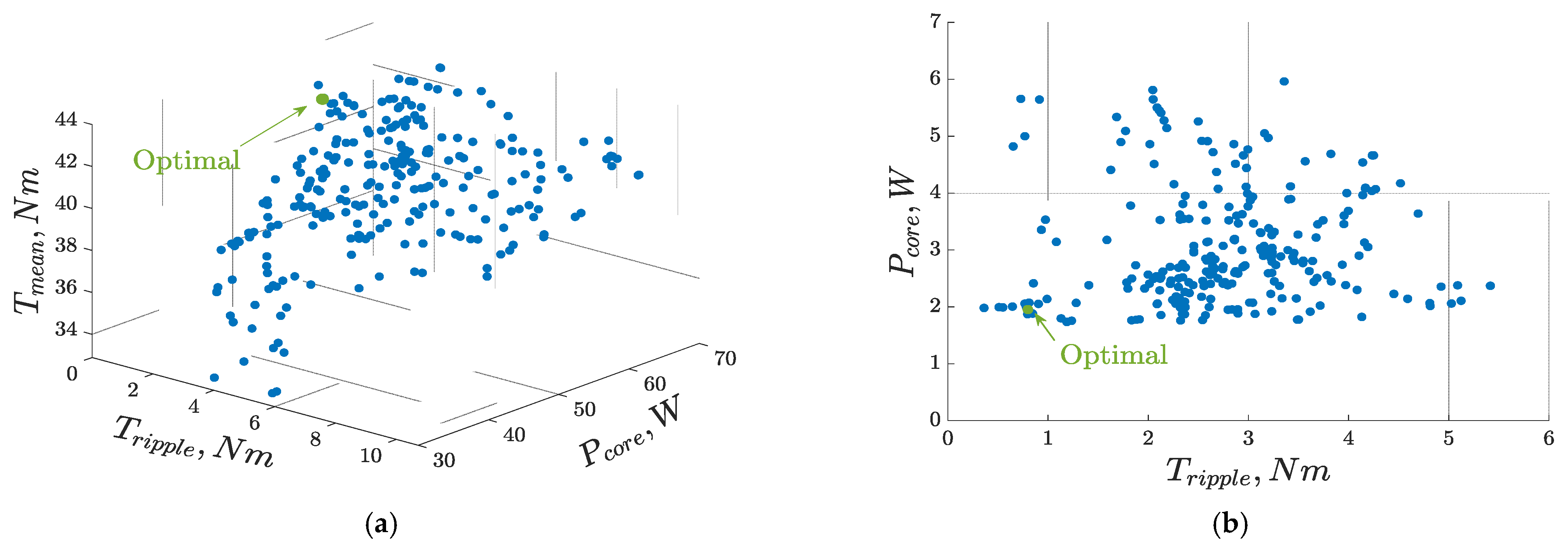
Multi-objective genetic algorithm (MOGA) optimization of the employed integrated OBC considering average output torque, torque ripple under propulsion, core losses under propulsion, torque ripple under charging, and core losses under charging.
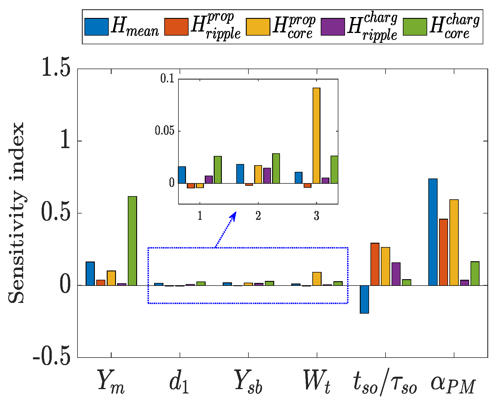
Sensitivity analysis to identify the influence of each design parameter on the various optimization performances of the SPM machine.
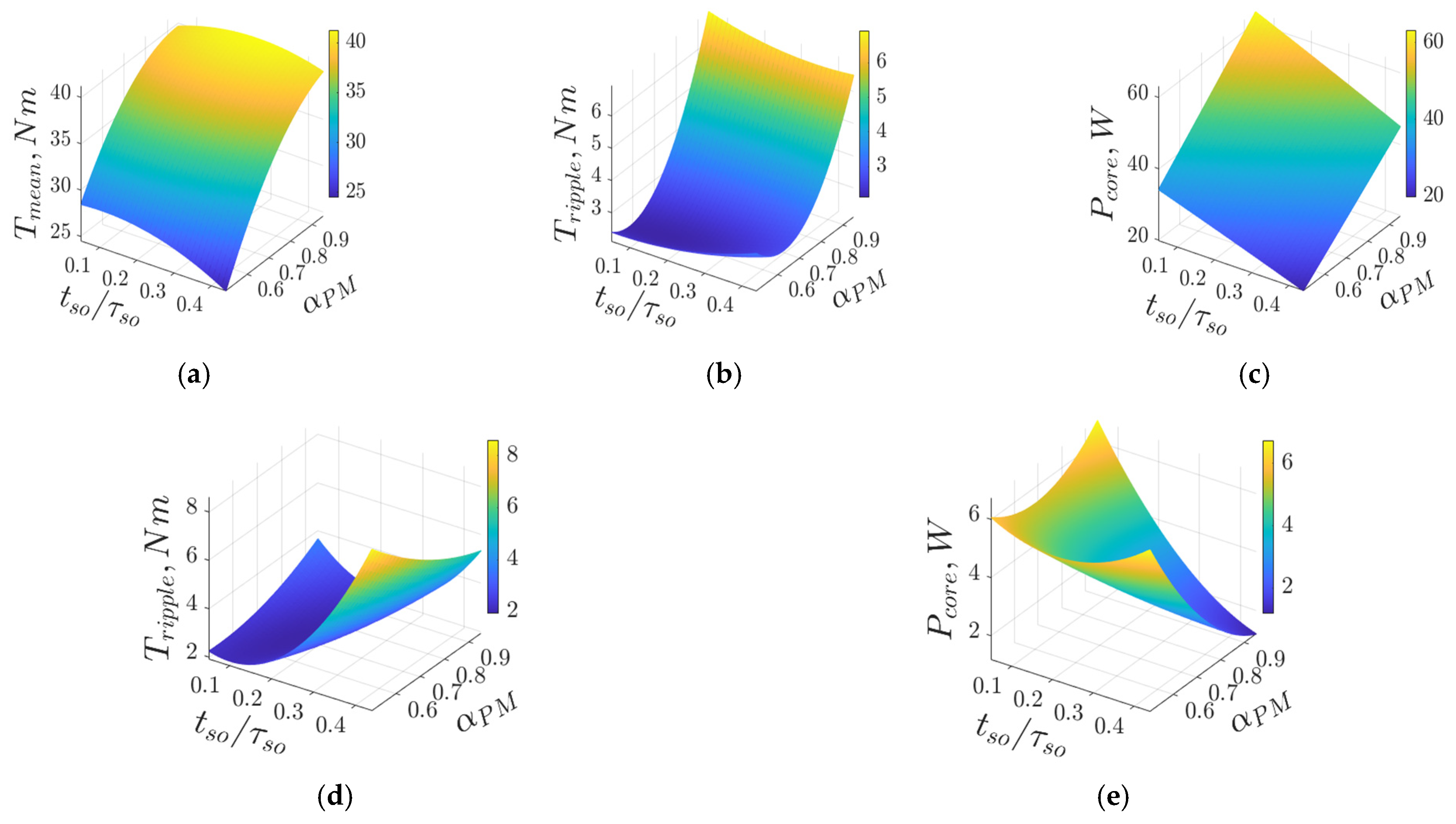
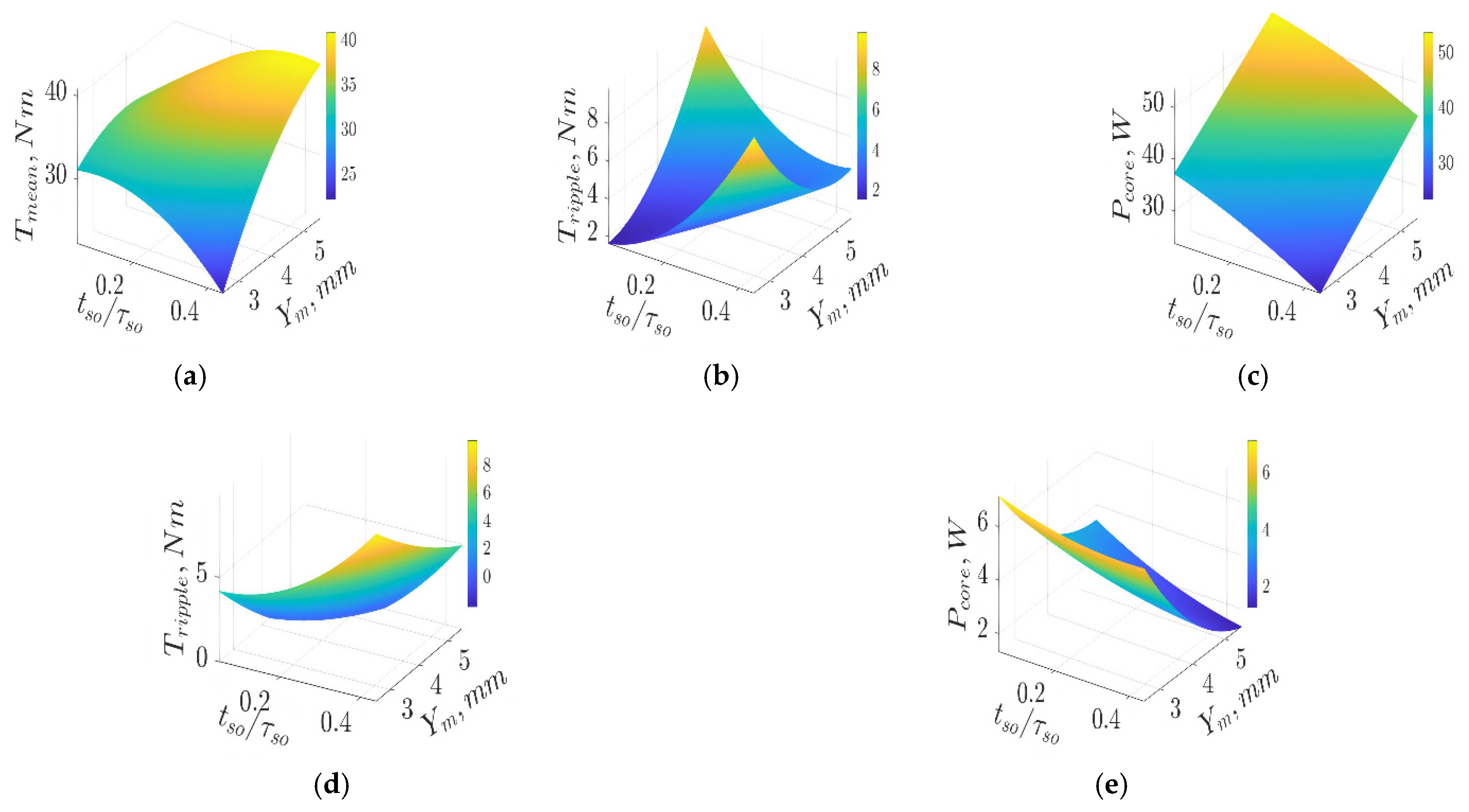
Response surface (RS) methodology to illustrate the relationship between the optimization objectives and high-sensitive design parameters.
Improved electromagnetic performances, namely, torque profile and core losses, under both operational modes were obtained and validated using finite element analysis (FEA).
2. Design Requirements and Integrated EV Charging Application
During charging mode, a low peak-to-peak torque ripple is required to reduce vibrations and noise in SPM machines. Core losses are also important, since they may lead to thermal demagnetization. Typically, application requirements are utilized as input to the machine design process. Design specifications for a scaled SPM machine are given in
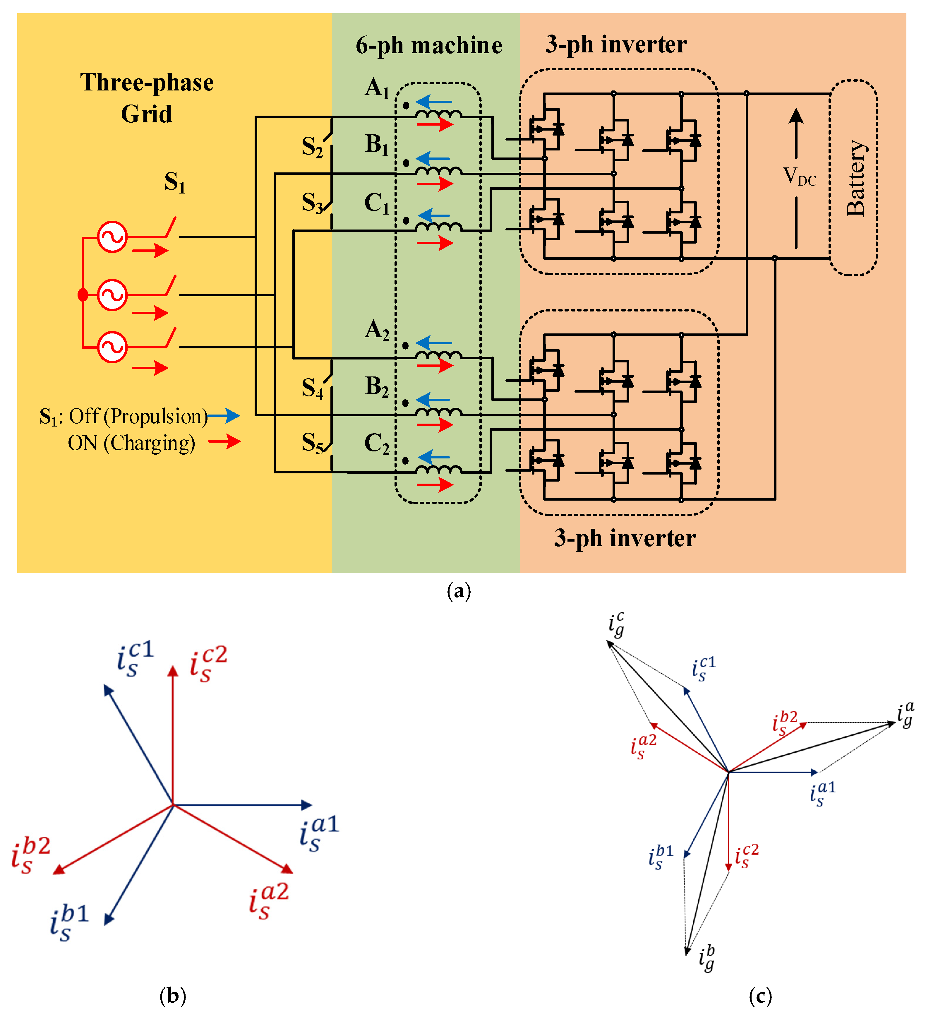
Table 1. In this paper, an asymmetrical six-phase integrated OBC is presented and designed, as depicted in
Figure 1. It comprises a six-phase machine, an inverter, and a battery connected to a DC-DC converter to control the DC link voltage. The DC link voltage is maintained at 600 V through the boost DC-DC converter [
19]. This study investigates the asymmetrical six-phase winding topology under propulsion (
), as well as charging (
), where
is the spatial phase angle between the two three-phase winding groups.
The proposed charger offers zero average torque production in the charging process when switch
is on and switches
are off. In that case, after synchronization, the grid line currents
,
, and
are divided between the first three-phase winding set with to the phase sequence
,
, and
and the second three-phase winding set with the phase sequence of
,
, and
. Thus, the resultant magnetic fields of the fundamental subspace from the two winding groups oppose each other, yielding a zero-torque-producing magnetizing flux component [
20]. Moreover, the reference charging phase currents are derived based on the direct component of the grid line currents, while the quadrature current component is set to zero. Unity power factor operation at the grid side is, therefore, guaranteed. The six-phase windings are utilized as grid-side filters [
21].
Under propulsion, switch is off, and switches are on, the two three-phase winding sets are connected in series forming a single neutral point topology, while each three-phase winding group is fed from a separate three-phase inverter. As a result, it can be noted that the proposed integrated OBC entails simple hardware reconfiguration between the propulsion and charging modes using switches .
3. Parametric MEC Model
The MEC model proposed in [
18] was developed for axial flux permanent magnet synchronous machines. The model is adjusted for radial flux permanent magnet synchronous machines (RFPMSMs) and is employed in the optimization process.
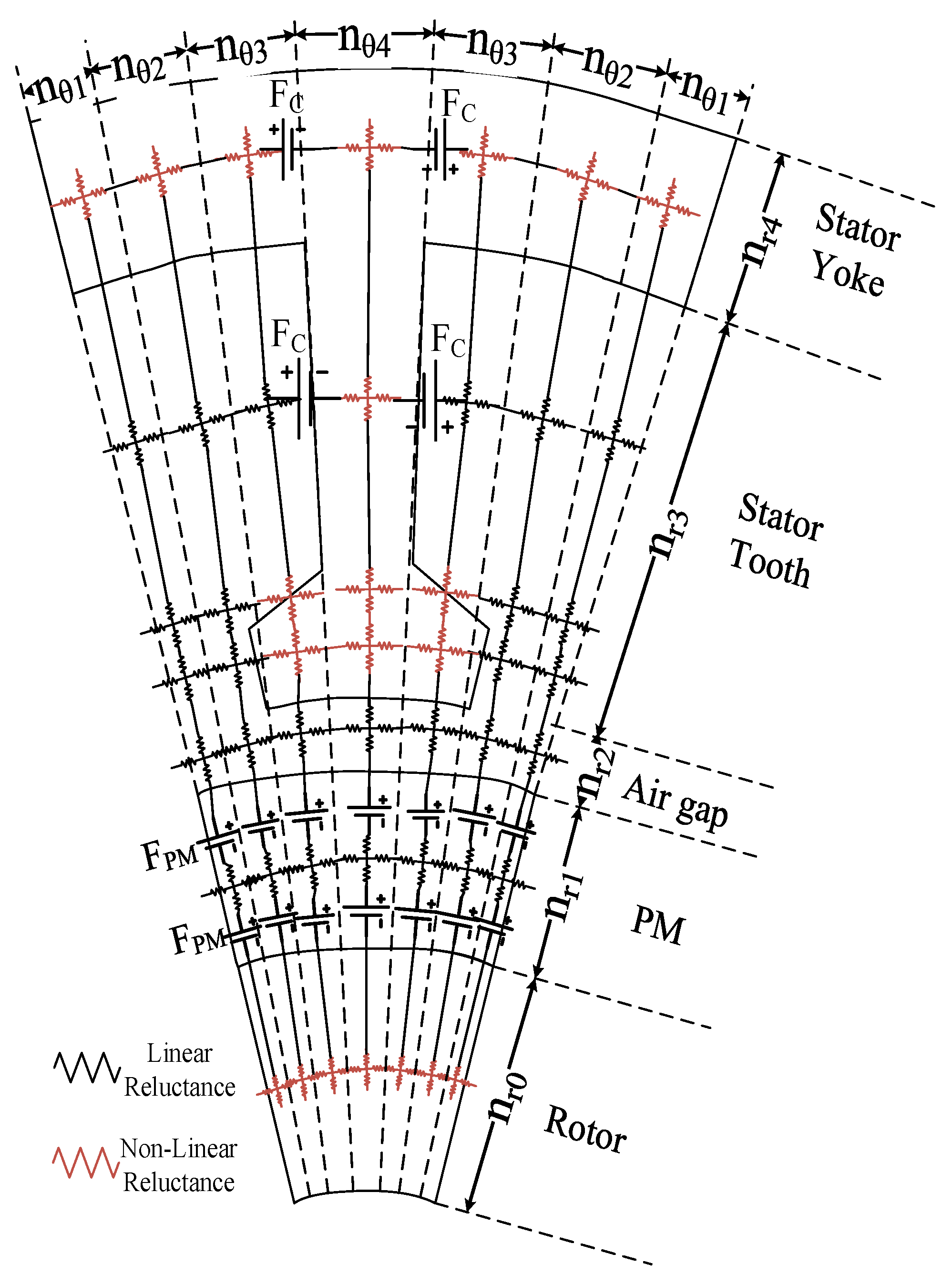
Figure 2 shows a one-tooth pitch defining all parts of the machine. The machine is divided into the rotor, the permanent magnets, the air gap, the tooth, and the yoke. Each tooth is divided into three parts consisting of the tooth tips and the tooth main part. Modeling of each part is performed using the MEC model. The saturation of the iron is included in the model by defining the non-linear reluctance elements. The connection between all elements is achieved using the loop matrices [
18].
The model is divided into several nodes. The values of = 2, = 3, = 2, = 10, and = 2 define the amount of discretization in the radial direction of the rotor yoke, PMs, air gap, stator tooth, and stator yoke, respectively. The discretization in the circumferential direction is defined by , , , and , where the value of , , , and used in this study are 8, 18, 13, and 13, respectively. This allows a detailed discretization in a certain part of the machine.
The system matrix consists of the reluctance elements and the magnetomotive force of the windings and the PMs.
Modeling of the PMs is performed by defining the magnetomotive force sources of the PMs as a Fourier series expansion in the circumferential direction for the PMs. Rotation of the PMs is performed by including the time in the Fourier series. The average magnetomotive force between two points can be easily obtained by an analytical formula. The details of obtaining the magnetomotive force of the PMs can be found in [
18]. Therefore, the stator and rotor reluctance matrices are kept constant and the only moving elements are the magnetomotive forces. This allows a fast and accurate solution for all electromagnetic parameters.
The reluctances of the machine consist of linear and non-linear elements. Therefore, a Jacobian matrix is defined to solve the machine by using the Newton–Raphson technique. The procedure and the equations can be found in [
18]. As shown in
Figure 2, the model considers the variation of the reluctances in the radial direction.
After obtaining the flux density distribution in all stator and rotor iron parts, the iron losses can easily be obtained using the concept of the iron losses separation technique [
22]. Finally, all electromagnetic parameters can be obtained. This includes the flux linkage for each phase, the full-load voltages, the mean torque, the torque ripple, the cogging torque, and the iron losses. All electromagnetic properties are verified by means of finite element (FE) analysis at the end of the article.
During the iterative design process, the model is fully parameterized in terms of the geometrical machine parameters, the number of slots, the number of poles, and the number of phases. The same model can be used for propulsion and charging modes.
7. Finite Element Validation
In order to validate the results of the proposed MEC-based design optimization approach of an SPM machine in the charging process of EVs, FE simulations of both the optimal and initial designs were developed using the JMAG
TM Designer 2D transient module. The two machines were assessed under both motoring and charging operational modes using the design parameters outlined in
Table 2 considering the optimized values of the key design parameters listed in
Table 5. Moreover, the results of the FE model were compared to the results obtained from the MEC model. Simulations of the two motors were carried out at the same speed of 1200 rpm.
Table 6 reveals the differences between the analytical and FE models with respect to the average torque production, the peak-to-peak torque ripple, RMS phase voltage, and core losses.
Figure 10 shows the torque profiles of the two machines under both operational modes. Under charging, the average torque production is nullified, which is the basic premise of the integrated OBC for EVs, as shown in
Figure 10b. Despite the fact that the initial and optimal machines offer the same average torque under propulsion and zero average torque under charging, the peak-to-peak torque ripple is considerably reduced when the optimal machine is employed under both operational modes.
For example, the torque ripple notably decreases from 10.9 to 1.59 Nm when the initial and optimal machines are employed, respectively, in the motoring mode. During charging, the torque ripple reaches 0.78 Nm for the optimal machine, compared to 2.56 Nm obtained when the initial design is utilized.
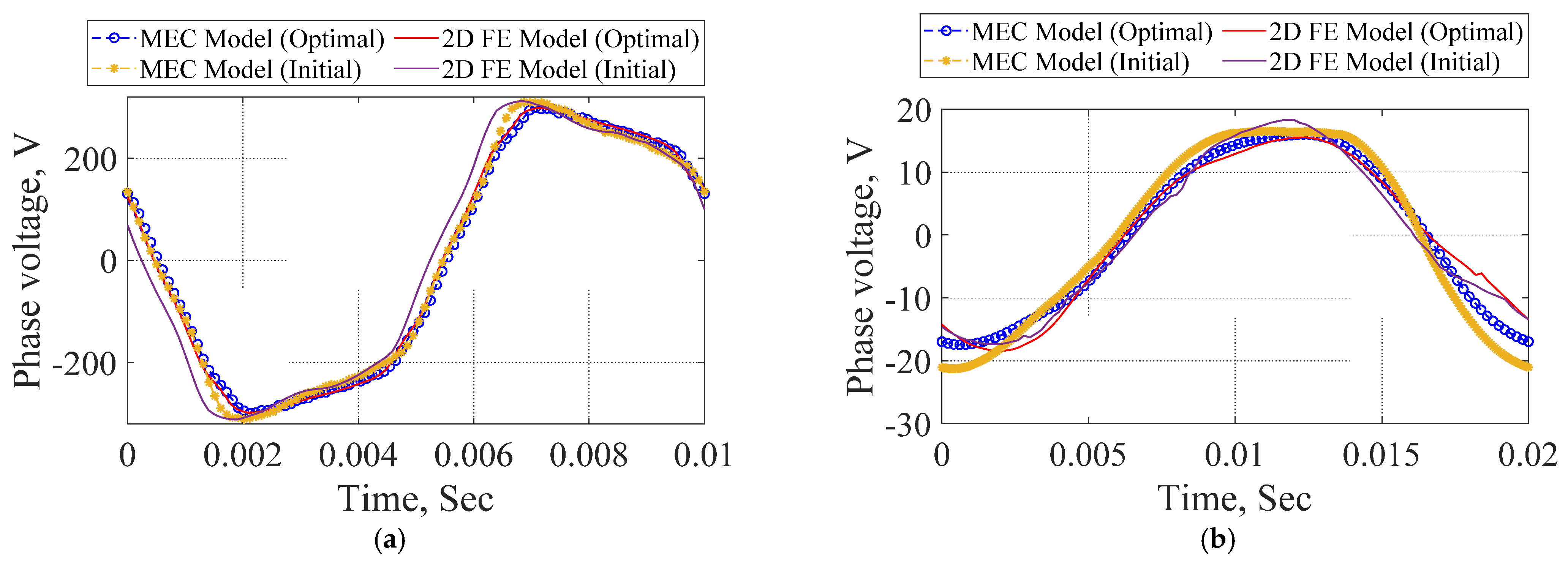
Moreover,
Figure 11 shows that both the initial and optimal machines have the same phase voltage profiles, i.e., same magnitude and frequency. Thus, similar average torque can be developed by the two motors at the same stator current in the propulsion mode, as shown in
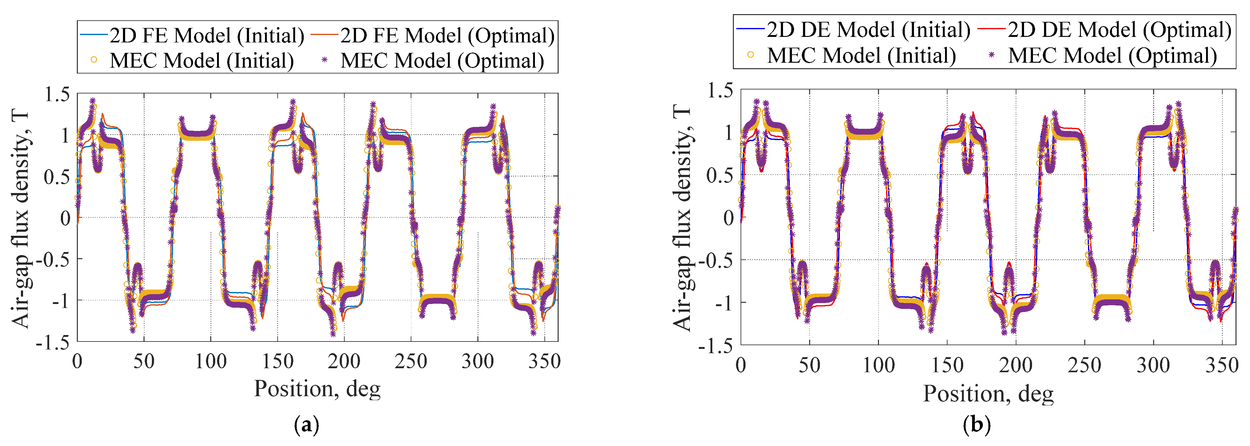
Figure 10a. The air-gap flux density of the two machines under both propulsion and charging operational modes is shown in
Figure 12. Appropriate utilization of the PMs can be observed, since the value of the air-gap flux density approaches 1.0 T under both modes. Finally, good agreement between the FE and MEC-based analytical models with respect to the electromagnetic performances in both the initial and optimal designs can be noticed under the various operational modes.
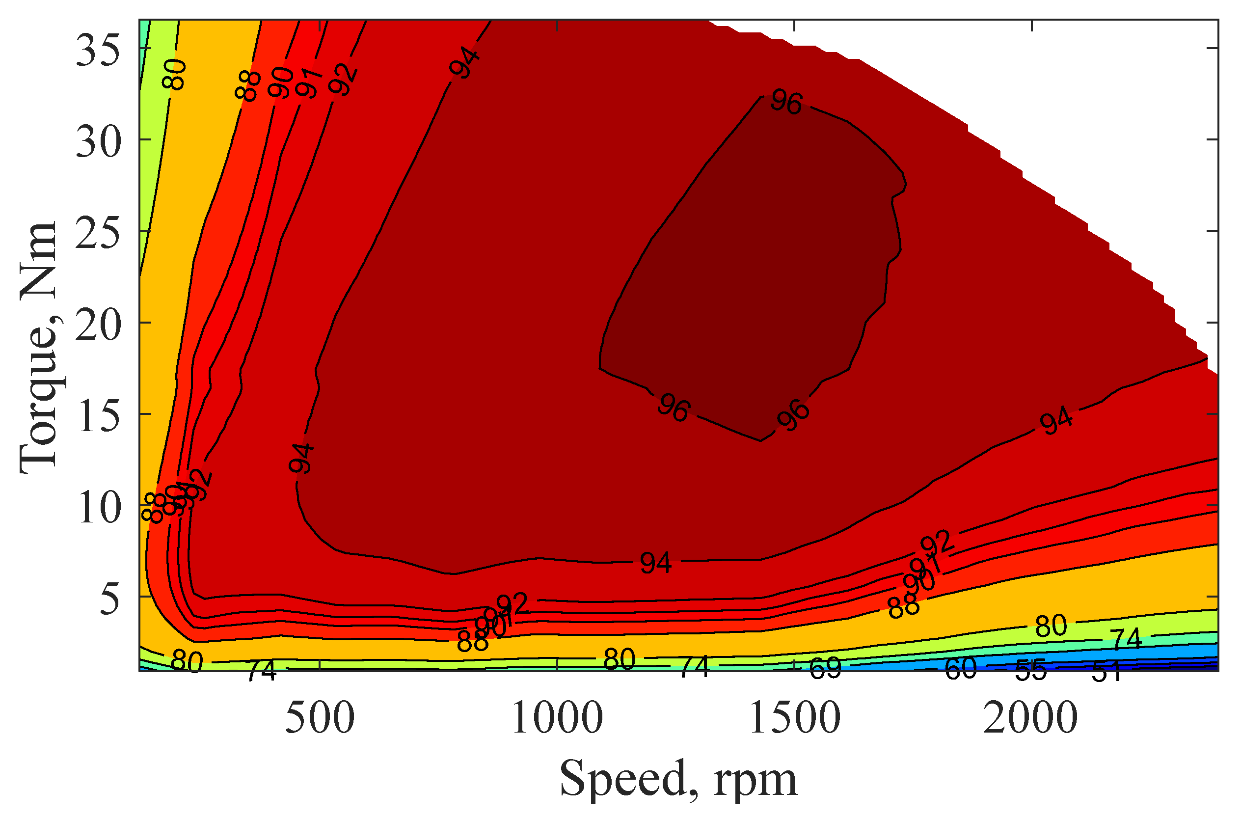
The efficiency of the optimized machine with different operating conditions is shown in
Figure 13. The optimal machine offers high efficiency at various operating points.
8. Conclusions
In this paper, an asymmetrical six-phase 12-slot/10-pole SPM machine is designed based on the MEC analytical model and optimized based on a multi-objective optimization approach under both the propulsion and charging modes of operation. A trade-off optimization design method among five design objectives (average output torque, torque ripple under propulsion, core losses under propulsion, torque ripple under charging, and core losses under charging) is efficiently achieved by using the response surface methodology and MOGA-based optimization. Both the theoretical findings and FE simulation results demonstrate the effectiveness of the proposed machine and the design optimization approach. Eventually, zero average torque production, lower peak-to-peak torque ripple, and lower core losses highlight the superiority of the optimized machine under the charging mode of operation when compared to the initial one.
From the perspective of optimization of PM machines, the proposed optimization approach can also be applicable to SPMs with different slot-pole combinations and other types of PM machines for torque improvement. Demagnetization capability and overall cost of PMs are also highly dependent on the geometrical dimensions of the employed machine. In the future, the authors will attempt to extend the proposed optimization approach for optimization of other performances, such as demagnetization capability and overall cost, so as to further verify its applicability and limitations.


 ,
, 


