Article

Performance of Multifunctional Smart PV-Based Domestic Distributed Generator in Dual-Mode Operation

by
Kumar Chandrasekaran
1,*,
Jasper John Sahayam
2,
Sundarsingh Jebaseelan Somasundaram David Thanasingh
3,
Sripriya Ramalingam
4,
Hady H. Fayek
5,
Nagananthini Ravichandran
6 and
Eugen Rusu
7
1
Electrical and Electronics Engineering, M.Kumarasamy College of Engineering, Karur 639113, India
2
Electrical and Electronics Engineering, Ponjesly College of Engineering, Nagarcoil 629003, India
3
Electrical and Electronics Engineering, Sathyabama Institute of Science and Technology, Chennai 600119, India
4
Electrical and Electronics Engineering, Annamalai University, Chidambaram 608002, India
5
Electromechanics Engineering Department, Faculty of Engineering, Heliopolis University, Cairo 11785, Egypt
6
Department of Electrical Engineering and Information Technologies, University of Naples Federico II, 80138 Naples, Italy
7
Department of Mechanical Engineering, Faculty of Engineering, ‘Dunarea de Jos’ University of Galati, 6200 Galati, Romania
*
Author to whom correspondence should be addressed.
Machines 2021, 9(12), 356; https://doi.org/10.3390/machines9120356
Submission received: 6 November 2021 / Revised: 9 December 2021 / Accepted: 11 December 2021 / Published: 15 December 2021
(This article belongs to the Special Issue Advances in Electrical Machines, Drives and Vehicles)

Abstract

:
This article briefs about a smart multifunctional single-phase inverter control for a domestic solar photo voltaic (PV)-based distributed generation that can work in both a grid-connected mode and an islanded mode by making the inverter mimic the operation of a synchronous generator. The control objectives were threefold: to provide the required active and reactive power for normal operating conditions and under varying operating conditions, to maintain the rated voltage and the rated frequency for the islanded mode, and to switch between the two modes of operation with the least amount of disturbance for the system while behaving as a virtual synchronous generator (VSG). The control structure is divided into three major loops: the outermost loop responsible for power control, the middle loop responsible for voltage control, and the innermost loop responsible for current control. The proposed control methodology incorporates the functionalities of the grid-connected and the islanded-mode control into a single complex structure and thus provides support to the grid under abnormal conditions while providing good-quality power to consumers under grid failure. The efficacy of the system is good. The operation under various modes were simulated in MATLAB Simulink, and the proportional integral (PI) controllers used for current controllers were tuned using particle swarm optimization (PSO). It can be concluded that the control structure becoming complex is benefitted by the added advantages of the smart PV system. The smart domestic PV system helps the prosumer to actively provide frequency support and voltage support, adding frequency support to the existing multifunctional PV systems.

1. Introduction

Renewable energy integration into power systems is constantly on the rise, and solar photovoltaic-based power generation is one of the two major forms of consumption of renewable energy. The advantage of solar photovoltaic power generation over wind-based power generation is that it is easy to include it as modules from small power levels to large power levels and in AC as well as DC microgrids. This is one of the reasons why the trend of increasing solar photovoltaic penetration across different countries and many developing countries is encouraging the installation of solar-based generation through providing financial support [1,2].
To interface the renewable power sources with the existing grid or to consume the power directly, power electronic converters are needed, and the added advantage of incorporating them is the control they provide over the inconsistent, varying power generation from sources like solar and wind. Because of the modular structure of solar panels, it is easier to add them for single-phase and three-phase electrical systems, and the general control structure of this is well established [3]. Unlike conventional rotating machine-based generators, the power electronic converters’ interconnection is having multiple issues due to fast switching, and many standards are established and are to be followed [4,5].
The standards provide guidelines for interfacing the limits of harmonics and stable operation under various operating conditions [6]. The power electronic converters provide flexibility for control at various levels and at various levels of time periods; due to fast-acting behavior, despite the complexity of the control, it is possible to respond to the transient changes that are constantly occurring in an electrical network. The basic control structure for a PV-based power electronic converter-interfaced system [7,8] can be split into three major sections where the first is responsible for power control, the second is responsible for voltage control, and the third is responsible for current control.
The current controllers have always been the center for attention as they form the heart of the control structure, and various current controllers for converters and in different applications have been used in experiments with their performance being studied [9,10,11]. With introduction of microgrids, the solar photovoltaic power generation can be completely isolated from the existing system, can be a part of the existing system, or it can have the capability of both modes of operation.
For synchronizing the static solar photovoltaic power source with converter interfaces to the grid, the voltage, the frequency, and the phase of the converter output should match with the grid, and these are the factors that provide the current reference to the current controller [12]. This process in the control requires a phase-locked loop (PLL) to obtain the grid frequency and use it for control purposes, which may introduce additional delay that slows the system. In this study, the proposed control obtains the grid frequency through a different method, and, due to the lack of a PLL, it is slightly faster.
The performance of the system is determined by the control structure and the converter structure, and various topologies are suitable for different requirements [13]. The advantage of utilizing the control-structure modifications for obtaining better performance over utilizing converter-structure modifications is that the cost, the size, and the protection requirements are lesser. This leads to fixing the converter structure and adding multiple functions to the control structure [14] to obtain the maximum out of the cost invested and, in turn, supporting the grid in various ways [15,16].
So, the current trend is to have a converter system that is capable of handling the power generated smartly [17] and that helps in meeting the needs of the consumer and the grid with the least amount of disturbance. Of this, the single-phase solar-power generation systems are becoming more popular due to their application for small consumers, who are becoming active participants in the system. It can be single-stage or two-stage based on the requirement of voltage and the control flexibility; advanced control techniques are used for optimally obtaining the current control [18], which adds up to the computation cost. In this study, a PI current controller was used due to its simplicity, and the values of kp and ki were tuned using the particle swarm optimization technique to obtain the optimal control for a particular operating condition [19].
The proposed control incorporates the grid connected and the islanded mode into a single control structure, and, with multiple functions, it is useful for helping in extracting maximum power from a PV system, injecting it to the grid, providing support to the grid, transferring to another mode smoothly, and maintaining load-following in islanded mode. As the PV power generation is susceptible to changes with environmental conditions [20,21], a battery is included to aid in smoothening the power output and for saving power when the local load is less than the local generation, providing power when local generation is less or not available. With the increased need of power quality enhancement [22], the smart PV control can be modified to include the function to work like a D-STATCOM.
A multi-functional PV system control utilizes the inverter used for interface of the renewable source to the grid as a modifier for the harmonics [23,24,25], and variations in the control schemes are carried out to improve performance of various functions. It has been widely accepted that, in the modern smart grids, this is good for both the prosumer as well as the grid side [26,27,28] as the power quality of the supply is improving, which is solving the issue of harmonic distortions introduced into the grid via various converters.
By adding real power-oriented functions to the already existing reactive power-oriented functions it is possible to modify the existing inverter control and make the voltage source inverter work like a virtual synchronous generator, taking care of both frequency and voltage variations. This study aimed at adding the frequency-oriented support to the existing voltage-oriented support provided by the multifunctional inverter-based schemes. By mimicking a synchronous generator, the stability of the system with high penetration of variable PV generation will be relatively improved to the current scenario [29,30,31]. This helps the prosumer to actively participate in the smart-grid environment without the fear of stability issues.
The article is organized as follows. The following section, Section 2 provides the control structure design of the proposed system for the multifunctional PV. After that, in Section 3, the system is presented with specifications and ratings of components. Section 4 explains the control scheme and design. Section 5 depicts the performance of the system. The proposed system was simulated in MATLAB Simulink, and the PI controller gains were tuned using particle swarm optimization (PSO); the program for tuning kp and ki was written in MATLAB code and shows the simulation results for system performance under various operating conditions. Finally, in Section 6, the work is concluded.

2. Smart Multifunctional Domestic Solar PV System

With an increase in modular small-scale solar photovoltaic generators for domestic purposes, the major issues faced are (a) a lack of a rotating component, which means no frequency support from the generator; (b) the computation of real and reactive power from voltage and current measurements in a single phase; and (c) the proper control action for various operating conditions. The first issue was solved by applying the concept of a virtual synchronous generator (VSG), which mimics the operation of a synchronous generator.
The second problem was solved by shifting the measurements into α-β domain and transforming the V-I measurements into P-Q to provide a similar reference for a synchronous generator. Conventional control techniques for a rotating machine can be translated to the fast-acting power electronic-interfaced PV system, but, due to a lack of consistent power generation due to various environmental conditions, a battery was taken alongside. The entire test system considered is shown in Figure 1, and various functions required are included in the VSG control block.
To obtain the maximum benefit out of the installed PV system, the maximum power has to be extracted electrically, and, for this, incremental conductance-based maximum power point tracking (MPPT) was used. Because there was a battery alongside PV, the inverter rating was chosen slightly higher than the real power output of PV, and it was for providing the necessary reactive power during the grid-connected or the islanded mode. It is generally good to operate at the unity power factor, as only active power is taken for economic factors, but, with the introduction of the smart-grid concept, the reactive power is also going to be taken for billing. Additionally, during abnormal conditions, the support from PV can be beneficial economically and technically for the stability.
By providing space for reactive power control, the inverter system can manage the power factor, the harmonics, and can help in the operation of an induction motor without affecting the grid side much. The design of each component and their control are discussed in the following sections.

3. System Modelling

3.1. PV, MPPT, and DC Link Control

The PV array is the renewable energy source, and it was modelled as modules of series and a parallel combination of PV cells to the obtain required power. The open-circuit voltage and the short-circuit current for a module cell were taken as 37.3 V and 8.2 A, respectively, with maximum power at V = 30.3 V. Assuming the rooftop of a home is large enough, a 3 kW array was taken as the test system source, and this will vary based on the space every home has. This was followed by a DC/DC converter, which implements MPPT, and the MPPT technique was taken as an incremental conductance and is shown in Figure 2.
The incremental conductance (INC) algorithm achieves MPP by constantly testing whether the change in conductance is equal to the system conductance, and, based on this, the operating point of the voltage and the current is changed. This is helpful when insolation is changing to get near the maximum power.
d P p v d V d c = 0 I p v + V p v d I p v d V p v = 0 d I p v d V p v = I p v V p v
The control of power is done through controlling the DC voltage, through a converter, and it is capable of operating in the buck or the boost mode as required. The duty cycle of the switch is D, and it is dictating the PV voltage as given below:
V p v V d c = D 1 D
Here, Vdc is the DC link voltage, which is maintained by the battery, and, relative to that, the PV voltage was varied to track the power. During change in input power to the PV, the battery provides power or absorbs power to maintain the DC link voltage, and together this unit is responsible for the dynamics of the DC side. By having the PV system use two stages (DC/DC and DC/AC), it decouples the control problems into the DC side and the AC side, which is beneficial.

3.2. Single-Phase Inverter

Because of the lower power rating and the nature of loads, a single-phase inverter is enough. An H-bridge converter was taken, and it was used as the inverter for converting the DC power from the DC link to AC power for the loads or for connecting to the grid. This is the component in which the majority of the functions through the control are implemented, and the inverter is followed by a filter to smoothen the output.
The control schema revolves around making the static inverter function like a rotating generator, and this forms the heart of the proposed system. The controller gains for the PI control used were tuned using PSO.

3.3. Battery-Energy-Storage System

Here, a Ni-Cad-based 25 Ah, 400 V rated battery bank was considered as the battery-energy-storage system. The aim of the battery system is to (a) maintain the DC voltage as the fluctuations from the PV module with specifications given in Table 1 can vary it; (b) provide or absorb power based on the inverter power command, the local load, and the PV output power; and (c) act as a source during times of no insolation, to provide real and reactive power.

4. Control Schematic and Design

The control schema’s objectives for the proposed multifunctional inverter control for the PV system are:
Real and reactive power control in both modes of operation, following the standards and making the static source to behave like a rotating synchronous generator.
Supply frequency and voltage support during abnormal conditions.
Meeting the power commands under varying insolation conditions.

4.1. Active Power Control Loop

The active power control of the converter has to be designed so that it behaves like a virtual synchronous generator (VSG), and, to do so, the actual synchronous generator has to be studied and incorporated into the inverter control loops. The mathematical representation of the synchronous machine dynamics is given by the swing equation, which relates the torque difference with inertia and the angular frequency, given as:
T m T e Δ ω R = J d ω d t
where
Tm—mechanical torque,
Te—electrical torque,
Δw—change in frequency (ω rated—ω actual),
J—inertia of the machine (rotating).
This is with the mechanical-motion-based terms like inertia and torque, which are not present in the static inverter; however, mathematically, the equivalent terms for an inverter can be formed, and, based on comparing the PV to a synchronous generator of similar rating, the mechanical factors can be converted to electrical terms. The active power is equivalent to torque and is controlled through speed control in a rotating machine, so it can be equated to the P-f control loop in the inverter control as shown in Figure 3a.
The inertial response is the machine’s kinetic energy change due to a change in the power output, and this can be mimicked by changing the power command in accordance with the change in frequency.
The real and the reactive power output of the inverter are given by:
P = v i cos ϕ   a n d   Q = v i sin ϕ
where “v” is the voltage measurement value at PCC, “i” is the current measurement value after filter, and φ is the power factor angle.
The SOGI was used in place of PLL for its better performance for dynamic variations in voltage, and this was used as one of the components for finding whether the system is in the grid-tied mode or in the islanded mode (See Figure 3b). It generates the alpha–beta components of the voltage from which the magnitude and the control references can be obtained:
V m a x = V α 2 + V β 2

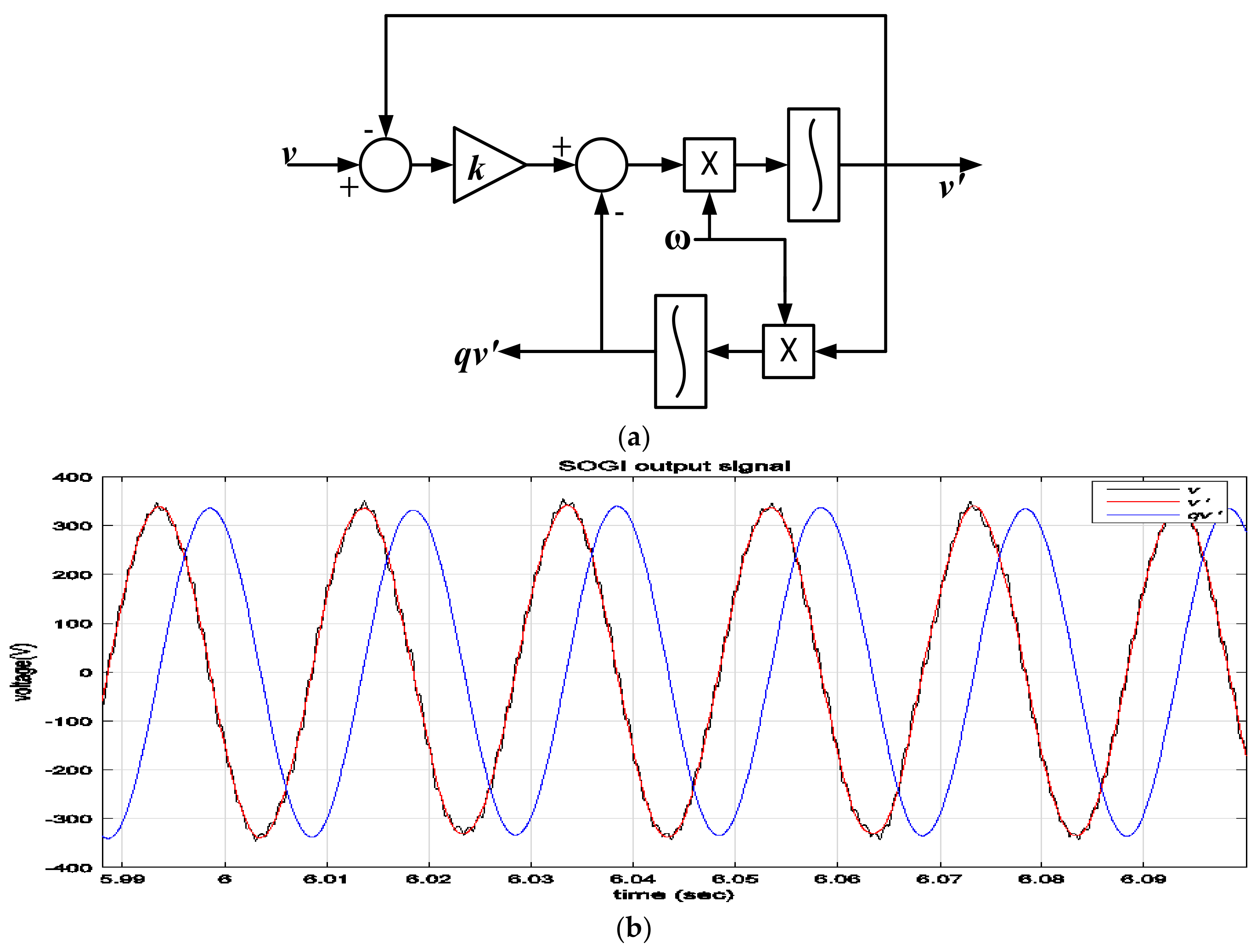
4.2. PCC Voltage Control

PCC voltage has to be controlled so that in the grid-tied mode, it is in phase with the grid voltage having the same frequency and magnitude, and, in the islanded mode, it is maintaining the rated voltage and the frequency. The advantage of having the VSG control is that reactive power control is coupled with voltage control, and so the control structure can regulate the frequency and the voltage or the real and the reactive power independently.
Figure 4 shows the control loops that can be used in the islanded and grid-tied modes, reducing the need for separate controls, and, because of this, the switching from one mode to another mode is smooth. This makes the frequency-based operations more efficient and makes the multifunctional inverter control respond to both voltage- and frequency-based variations in the smart-grid scenario.

4.3. System Stability

There are many instances in the literature showing the stability issues arising due to the larger penetration of renewable energy sources, especially photovoltaic sources [32,33] due to the lack of inertial response in the inverter-based interfacing. Adding the virtual inertia to the photovoltaic-inverter control loops improves the system stability and makes the system inclusive for the growing photovoltaic installations. In the islanded mode without proper frequency and voltage support from the photovoltaic system [34] and without the information about the frequency of the system in the power control loop, the system becomes unstable. The proposed controller was tested for starting an induction motor with an isolated smart photovoltaic-inverter system, and it was capable of working satisfactorily. The proposed control with a large number of smart photovoltaic inverter systems can cumulatively reduce the voltage and frequency instability issues to a certain extent.

5. Results and Discussion

The test system had a PV with an MPP of 3 kW and 400 V with 7.5 A ratings, assisted by a 400 V, 25 Ah battery energy system. The local loads were assumed to be less than the total power rating of these two components and were connected to the grid. The test system with the proposed control was studied under various conditions such as: variations in the electrical load and generation as well as variations in the grid conditions.

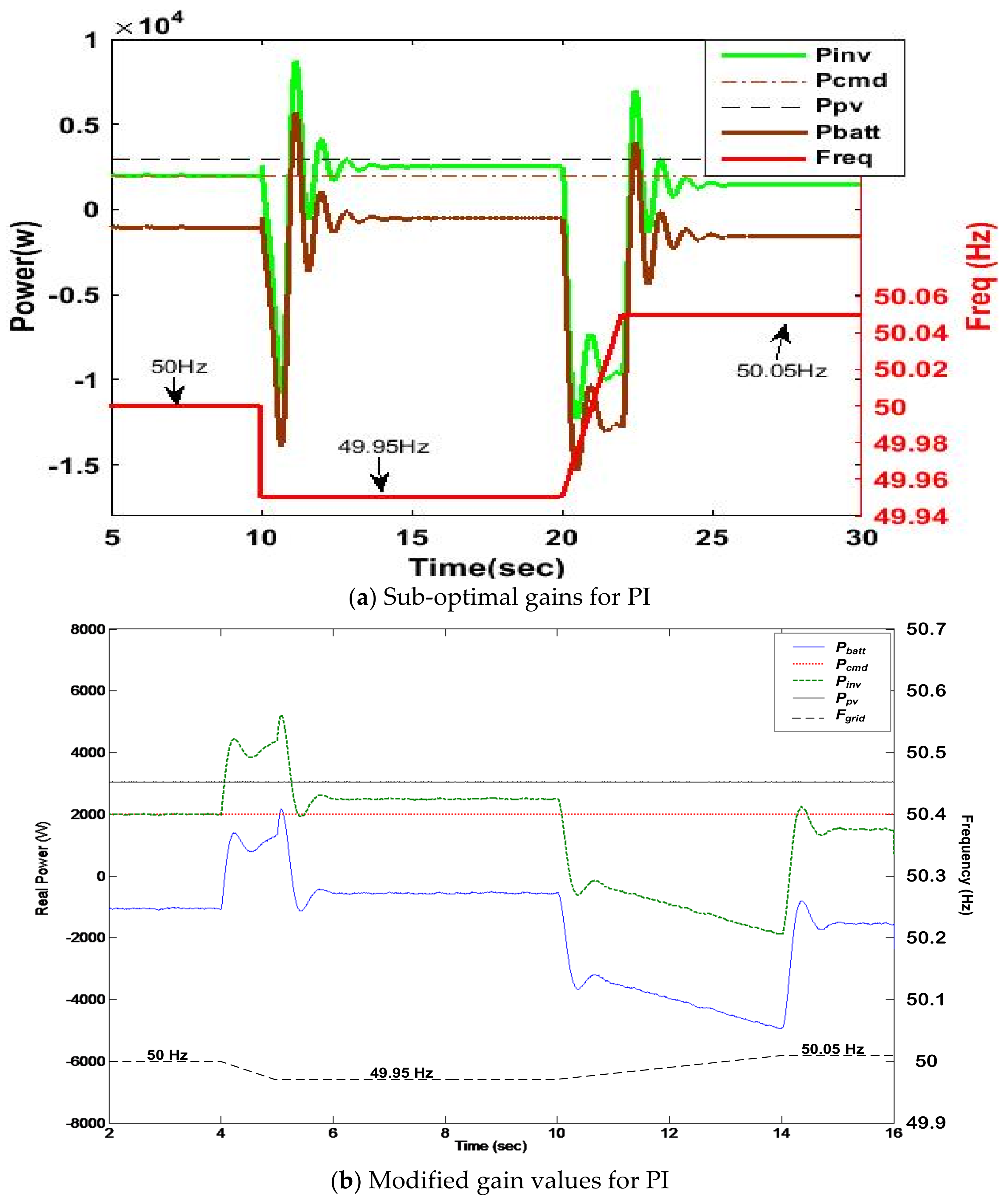
5.1. VSG Operation and Frequency Support

This case study is the most important one, because this is where the VSG operation is best visible, and the frequency support for grid variations is usually absent in PV-based generators generally. Like a synchronous generator adjusting its kinetic energy instantaneously due to mechanical inertia, the VSG is adjusting its power output with respect to the frequency changes, and, based on this, it tries to bring back the grid frequency to the natural rated value.
In a synchronous machine, the inertia constant dictates the dynamic response, and since the frequency loop is having a virtual inertia constant, the dynamic response is similar. For an increase in frequency, the proposed VSG should be behaving like a decelerating machine, and, for a decrease in frequency, the proposed VSG should be behaving like an accelerating machine, so that the active power decreases or increases to bring the frequency to the nominal value.
The inverter determines how much power should be adjusted and in what direction it must be adjusted, while the battery absorbs or provides additional power that cannot be controlled directly by the PV system. Figure 5 shows this under two sets of controller gains; Figure 5a shows conditions for various grid-frequency variations, and because the gains were not tuned properly or were sub-optimal, the response was oscillatory. This shows that even though it had a good steady-state response of tracking the commands and maintained frequency support, the dynamic response was lacking in performance.
This is where the optimization algorithm, particle swarm optimization (PSO), was applied so as to tune the gains or to reach near-optimal gains. The PSO variables were chosen as kp and ki within their limits and under these constraints, the simulation file of the proposed system was called each time the kp and ki were modified from the start of the iterative process to the end. For every run of the simulation file, for various reference changes, the performance of the controller was objectively measured through the error in tracking. By using this objective function, the local best and the global best for each iteration was found out, and, using this, the position and the velocity were updated and checked whether they were within the limits. Convergence of both the variables with low tolerance was chosen as the end condition for the iterative process.
The performance of the tuned controller is shown for similar variations in frequency with the same system in Figure 5b.
Initially, the kp and ki gain limits of the PI controller were set, then, for that position and velocity, they were initialized.
pos_Kp = Kpmin.*ones (16,1) + rand(16,1).*(Kpmax-Kpmin);
pos_Ki = Kimin. *ones (16,1) + rand (16,1). *(Kimax-Kimin);
vel_Kp = Kpmin. *ones (16,1) + rand (16,1). *(Kpmax-Kpmin);
vel_Ki = Kimin. *ones (16,1) +rand (16,1). *(Kimax-Kimin);
For solving the optimization problem, iteration (k) was chosen as 100 and population (p) was chosen as 30 for which the simulation file for the single-phase VSG PV system was called for each candidate solution in each iteration. For each p in each k, the objective function was taken as the error in the tracking of the system. For tuning purposes, it was assumed that there is a variation in the reference value in the Simulink file, and the tracking error was calculated from different parameters following the variation.
objfxn (p, k) = f (steady state error, rise time, settling time);
Following a disturbance, the system has to reach the steady state with minimal error with consideration of the rising time and the settling time for which the error was calculated from the simulation after each run.
objfxn (p, k) = error(size(error,0.5))/106;
From the objective function, the local best (Pbest) and the global best (Gbest) were found, which were used along with confidence parameters to update the position and the velocity of the kp and ki values. The updated values were checked against the minimum and maximum values and then put for the next iteration.
vel_Kp = w(:,1).*vel_Kp+c1.*rand(16,1).*(P_best(:,1) − pos_Kp) + c2.*rand (16,1).*(G_best (1,1)*ones (16,1) − pos_Kp);
vel_Ki = w(:,2).*vel_Ki + c1.*rand(16,1).*(P_best(:,2) − pos_Ki) + c2.*rand (16,1).*(G_best (1,2)*ones (16,1) − pos_Ki);
pos_Kp = pos_Kp + vel_Kp;
pos_Ki = pos_Ki + vel_Ki;
By altering the values of the confidence parameters (c1 and c2), the candidate solution initialization, the size of the candidate, and the iteration count, the two-dimensional search of kp and ki can be done. For every iteration and for every population value of position and velocity, the Simulink was called and was run. Because it is a design problem, the time was not constrained, but, for 30 populations, a 100-iteration PSO program with 30 s simulations, one iteration was taking roughly 30 min on i7-7th gen PC with MATLAB 2019 with 16 GB RAM.
The future scope of this study is to explore various optimization parameters and techniques to optimally control the system. Modified PSO- and ant-colony-optimization-based tuning are potential alternatives for reducing the tuning time and the over-shoots in the controller output.
For Figure 5b, the operating conditions are given as:
The system was assumed to be operating at 1000 w/m2 insolation, and so the solar PV output was 3 kW.
The command set for active power was 2 kW, and this has to be maintained always, as it is given by the system operator in the grid-tied mode or in the islanded mode, and it is the minimum power required for the operation of the loads.
At time t = 4 s, the frequency was decreased with a ramp and was reduced to 49.95 Hz by time t = 5 s. For this reduced frequency in the grid (or due to the load increase), the power output from the inverter had to change. Because it is a reduction in frequency, the inverter has to provide more power to compensate this change as it has to behave like a rotating machine increasing its speed.
The increase in output power of the inverter is the gradual decrease in battery charging power, and, due to the inertial response, there is an overshoot. This is because there is no electrical damping designed for the virtual inertia in the system.
After meeting the required set point command, the VSG PV system provides slightly higher power to bring the frequency back to the nominal value of 50 Hz. Because it is the grid frequency, which was taken as an infinite source, the frequency was not changing—but the real power output from the inverter was kept higher than the commanded value (2.5 kW against 2 kW set point).
At time t = 10 s, the frequency was increased like a ramp, and by time t = 14 s, it was settled at 50.05 Hz.
Similar to the previous operation, the output power of the inverter was adjusted, and the final value of it was lesser than the commanded value. This means that the VSG PV system was acting like a decelerating machine to absorb the excess of power until the frequency reached 50 Hz.
The proposed control makes the inverter work like a rotating machine with inertia, which helps the smart PV system to respond to frequency variations as shown in Table 2. In a scenario with a high penetration of PV, if this is not present, the variations in load may lead to system instability or an unnecessary islanding mode. This is avoided by introducing the Δωf-based control in the system by simply modifying the control loops.

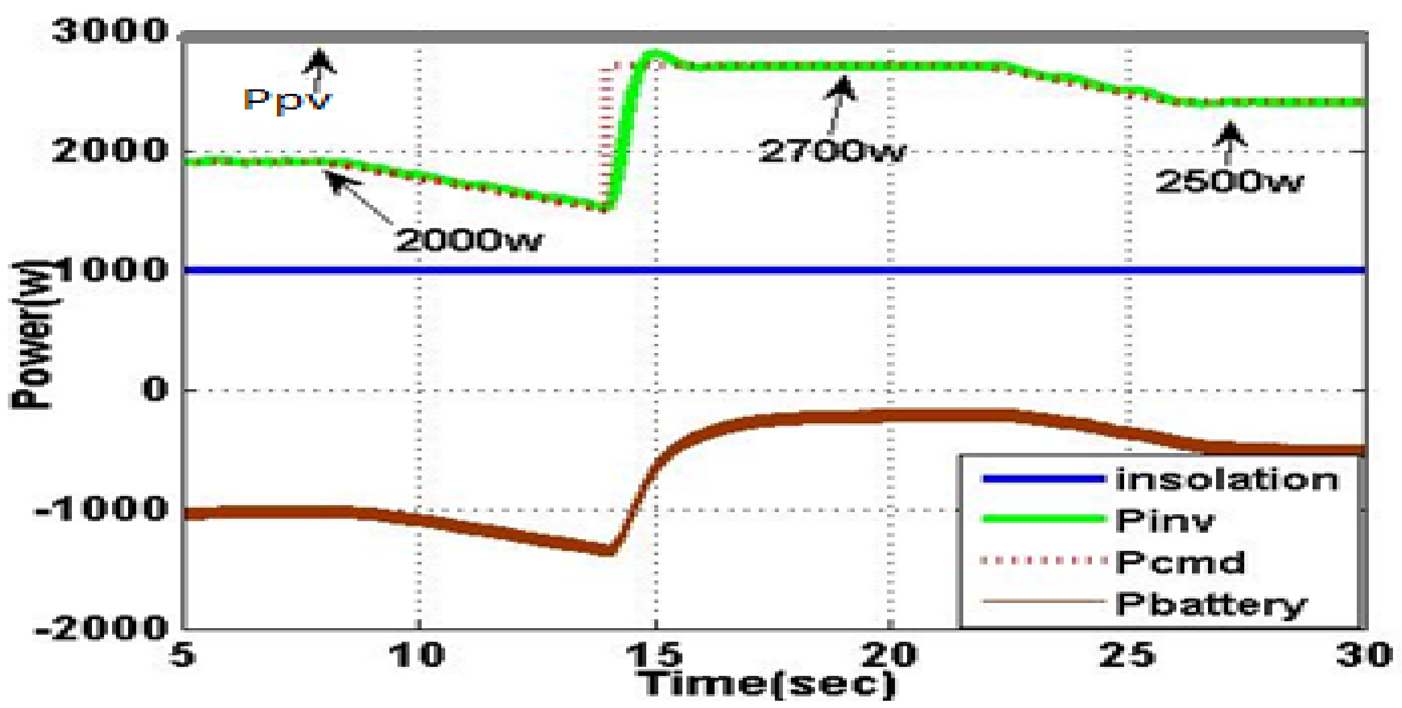
5.2. Set Point Change to Active Power

Assuming insolation is constant, the system is tested by varying the active power command given. In the grid-tied mode, the command is given by the distribution system operator, and, in the islanded mode, this is the load power as the system has to be in the load-following mode.
Like with insolation changes, the command change was taken for a sample operation of a ramp change and a step change, where the step change is for sudden switching on of a large load. Initially, the power output was 3 kW under 1000 W/m2 insolation, and the command was kept as 2 kW. This means that the excess power was absorbed by the battery, and the battery was assumed to be discharged during night time. The power command was decreased with a ramp, at time t = 5 s, and then, at t = 14 s, a step change was given; then, at t = 22 s, again a ramp decrease occurred, and then, at t = 26 s, 2500 W was given as the increased power command from the initial stage.
The control structure designed is capable of tracking the change in real power quickly, and, based on the consumption, the excess power is fed to battery and is shown in Figure 6 and Table 3.

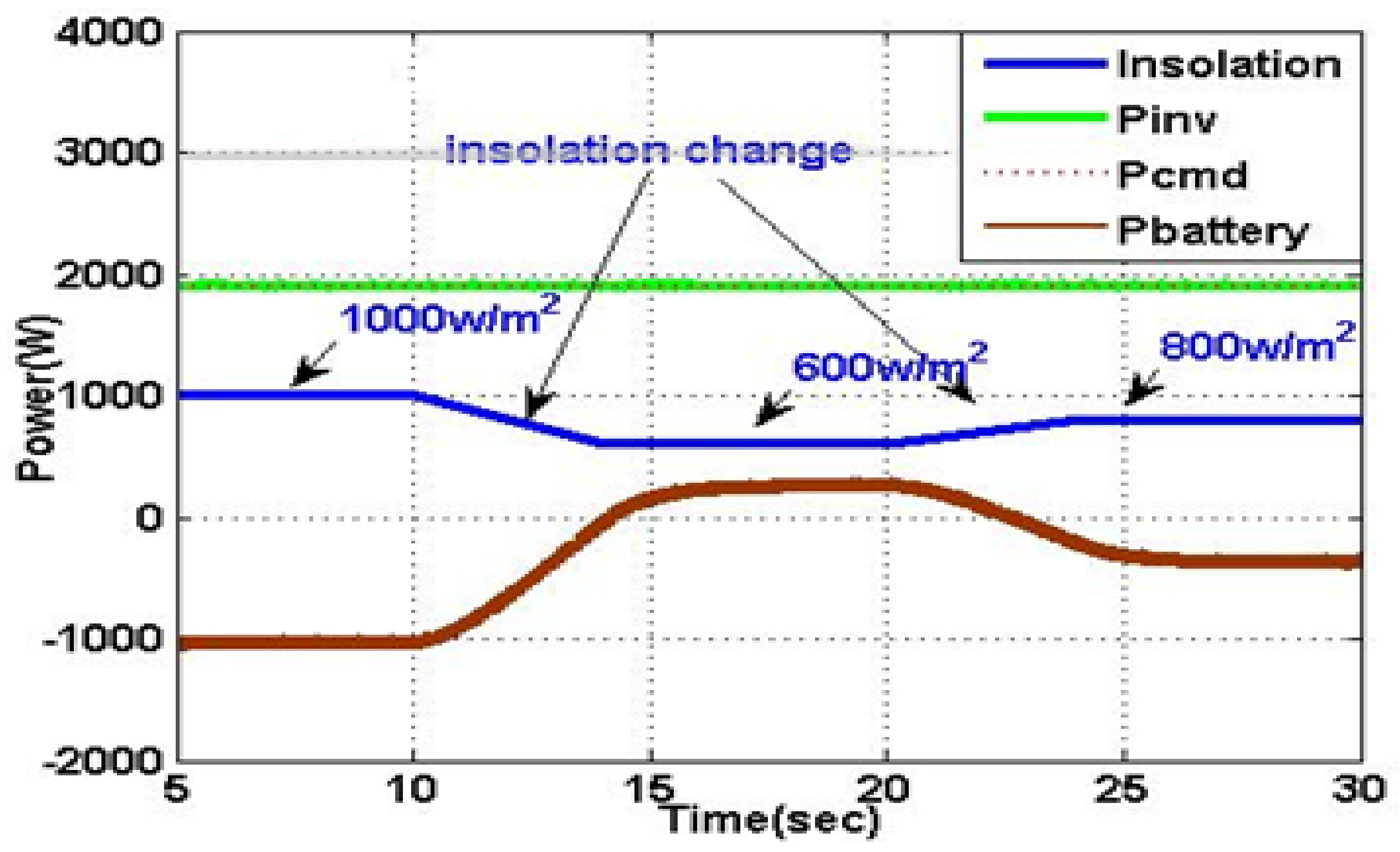
5.3. Insolation Changes

Sunlight will be constantly changing in practical applications, and a sample portion of such a change was implemented here. Normally, the insolation is kept at 1000 W/m2, and it is changed with a ramp up and ramp down, settling to a lower value, and the inverter output power is given as the Pcmd.
Even with varying insolation radiation, the proposed PV-battery source is to be delivering the set points of active and reactive power. In the grid-connected mode, it is usually the power commands, but, in the islanded mode, this is also the power required for maintaining the voltage and the frequency at their set points.
The ramp rates for insolation variations were set to 200 W/m2 per sec and 66.67 W/m2 per sec, and the lowered settling points were 600 W/m2 and 800 W/m2. The grid command was set to 2 kW, and the PV output at 1000 W/m2 was 3 kW; because the inverter output was fixed, the variation in the PV output was depicted through battery power. Negative power shows that the excess power from the PV system is stored, and when insolation is reduced to 600 W/m2, the battery is providing power and is shown in Table 4 and Figure 7.

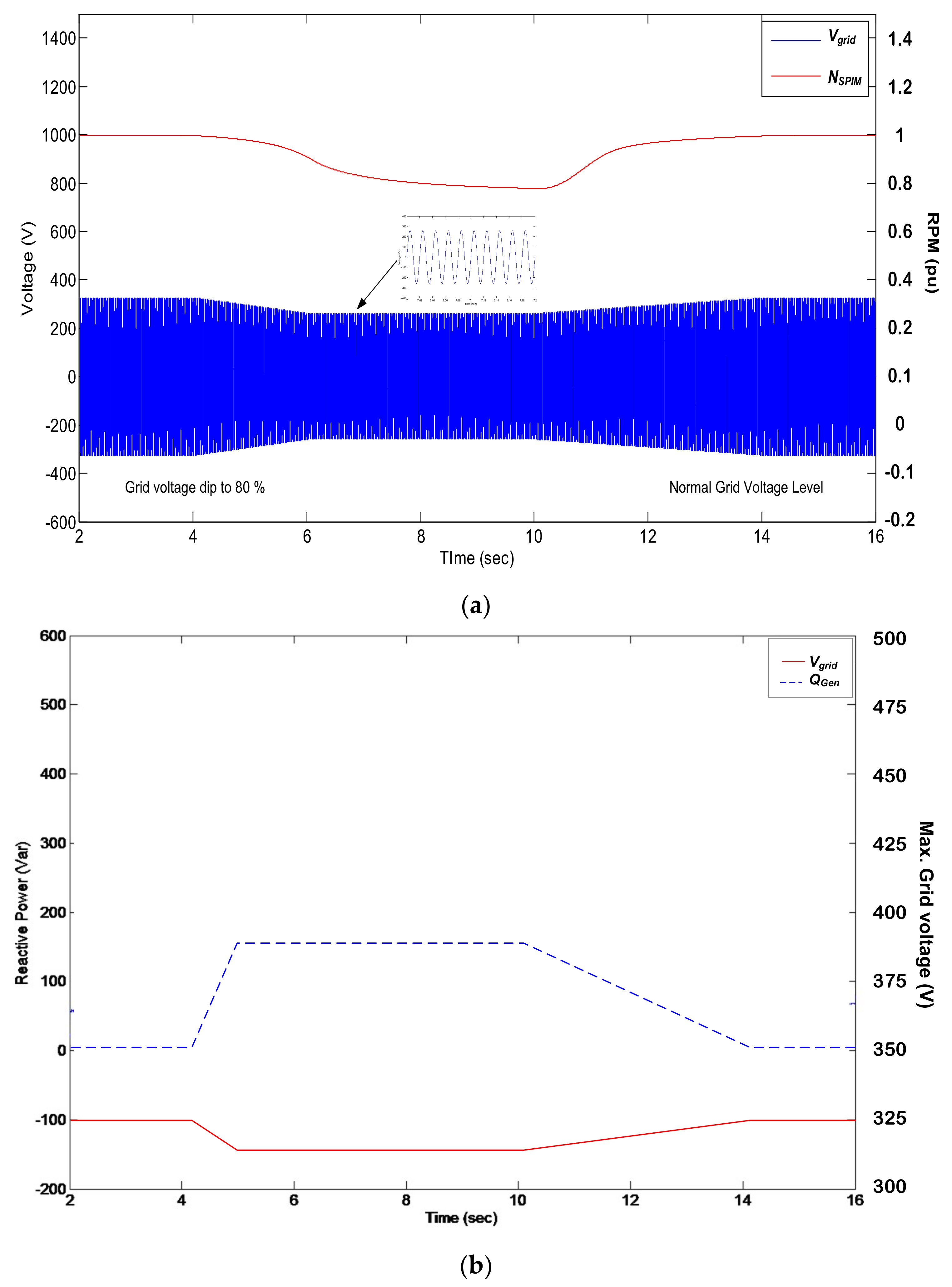
5.4. Voltage Support

The smart PV system has to provide voltage control and voltage support, because the fluctuations in the single-phase system are constant and high. The inverter module has to adjust reactive power output to match voltage requirements, in the grid-tied mode, when the voltage varies due to abnormal conditions like a fault or a line outage and, in islanded mode, for sudden changes in loads and for the operation of induction-motor-based loads.
To show the effective working of the Q-V loop, the rated voltage was reduced as a ramp down at time t = 4 s, and, at time t = 5 s, it was settling at 80% of the nominal voltage. This is shown in Figure 8a, and because it is an induction motor load taken for testing of this condition, the motor speed reduced due to voltage variation. This case is with Figure 8b where the inverter module is providing reactive power to try to maintain the nominal voltage and without the additional support.
The induction motor load will be struggling to maintain the torque, as it stalls due to an abrupt reduction in voltage. The reactive power control loop is also responsible for the load-following mode, and it is making the VSG work like a synchronous condenser when needed.

6. Conclusions

This study proposed a control schema for a multifunctional PV for modern smart-grid domestic applications, and, by incorporating the virtual-synchronous-generator-based control techniques, it is easy to include the real and the reactive power control for the grid-tied and the islanded mode operations into a single loop. By incorporating both modes of control into a single structure, the switching from one mode to another is easy and smooth. The traditional PI control was implemented, and the controller gains were tuned using an optimization algorithm, particle swarm optimization, to reach near-optimal values of a proportional and integral constant. The operation of the proposed system for various conditions was tested in Matlab Simulink, and from the results, it is visible that the proposed control is capable of providing additional functions needed for the upcoming smart-grid-based homes. The smart PV inverter control is capable of meeting the changes in frequency, either due to grid variation or load variation, and, at the same time, it is capable of providing reactive power support to maintain the voltage or to bring back the voltage to the nominal value due to grid variations or load variations with the help of a battery-based energy-storage system. Additionally, the performance of the system for insolation variation and satisfactory working with an induction motor without any issues was observed. With more renewable energy sources being included and PV, especially, being suitable for domestic purposes, the smart PV control enables the residents to actively participate in the frequency and the voltage support. The VSG operation aids higher penetration of the PV panels and assists the prosumers in the smart-grid environment to pro-actively support the operation by virtue of the introduced virtual inertia. Additionally, the proposed control helps in operating for the grid-tied and the islanded mode with a single control scheme instead of mode switching producing disturbance during the transition, all while providing required active and reactive power under various operating conditions.

Author Contributions

Conceptualization, K.C. and J.J.S.; methodology, S.J.S.D.T. and S.R.; validation, H.H.F. and J.J.S.; formal analysis, K.C. and N.R.; investigation, J.J.S.; resources, S.J.S.D.T. and S.R.; data curation, K.C. and S.J.S.D.T.; writing—original draft preparation, J.J.S. and S.R.; writing—review and editing,. H.H.F., N.R., E.R. and K.C.; visualization, H.H.F. and E.R.; supervision, K.C. and E.R.; project administration, N.R. and H.H.F.; funding acquisition, H.H.F. and E.R. All authors have read and agreed to the published version of the manuscript.

Funding

The research has no external funding.

Institutional Review Board Statement

Not applicable.

Informed Consent Statement

Not applicable.

Data Availability Statement

No data except that in the paper.

Conflicts of Interest

The authors declare no conflict of Interest.

Nomenclature

VSGVirtual Synchronous Generatorsynchronous generator
PIProportional Integralintegral
PSOParticle Swarm Optimizationswarm optimization
PVPhotovoltaic
PLLPhase Locked Loop-locked loop
MPPTMaximum Power Point Trackingpower point tracking
INCIncremental Conductanceconductance
Ni-CadNickel Cadmiumcadmium
SOGISecond Order Generalized Integrator-order generalized integrator
PCCPoint of Common Couplingcommon coupling
MPPMaximum Power Pointpower point

References

  1. International Renewable Energy Agency (IRENA). Renewable Energy Statistics 2019; Technical Reports; John Wiley & Sons: Hoboken, NJ, USA, 2019; ISBN 978-92-9260-137-9. [Google Scholar]
  2. A Report on. Off-Grid and Decentralized Solar Application Scheme: Operational Guidelines for Grid Connected Rooftop and Small Solar Power Plants Programme; Government of India, Ministry of New & Renewable Energy: New Delhi, India, 2014.
  3. IEEE Standard Committee. IEEE Standard for Interconnection and Interoperability of Distributed Energy Resources with Associated Electric Power Systems Interfaces; IEEE Std. 1547-2018 (Revision of IEEE Std. 1547-2003); Institute of Electrical and Electronics Engineers, Inc.: New York, NY, USA, 2018; pp. 1–138. [Google Scholar]
  4. IEEE Recommended Practices and Requirement for Harmonic Control on Electric Power System; IEEE Std 519; Institute of Electrical and Electronics Engineers, Inc.: New York, NY, USA, 1993.
  5. IEEE Standard Committee. IEEE Standard for Interconnecting Distributed Resources with Electric Power Systems; IEEE Std. 1547; Institute of Electrical and Electronics Engineers, Inc.: New York, NY, USA, 2003. [Google Scholar]
  6. International Electro Technical Commission (IEC). Characteristics of the Utility Interface for Photovoltaic (PV) Systems; IEC 61727; IEC: Geneva, Switzerland, 2004. [Google Scholar]
  7. Ciobotaru, M.; Teodorescu, R.; Blaabjerg, F. Control of Single-Stage Single-Phase PV Inverter. EPE J. 2006, 16, 20–26. [Google Scholar] [CrossRef]
  8. Teodorescu, R.; Liserre, M.; Rodriguez, P. Grid Converters for Photovoltaic and Wind Power System; John Wiley & Sons: Hoboken, NJ, USA, 2010. [Google Scholar] [CrossRef]
  9. Kazmierkowski, M.P.; Malesani, L. Current control techniques for three-phase voltage-source PWM converters: A survey. IEEE Trans. Ind. Electron. 1998, 45, 691–703. [Google Scholar] [CrossRef]
  10. Sathiyanarayanan, T.; Mishra, S. Performance of FCS-MPC based current controller for VSC based DG sources. In Proceedings of the 20th National Power Systems Conference (NPSC), Tiruchirappalli, India, 14 December 2018; pp. 1–6. [Google Scholar]
  11. Bouzid, A.M.; Guerrero, J.M.; Cheriti, A.; Bouhamida, M.; Sicard, P.; Benghanem, M. A survey on control of electric power distributed generation systems for Microgrid applications. Renew. Sustain. Energy Rev. 2015, 44, 751–766. [Google Scholar] [CrossRef] [Green Version]
  12. Blaabjerg, F.; Teodorescu, R.; Liserre, M.; Timbus, A.V. Overview of control and grid synchronization for distributed power generation systems. IEEE Trans. Ind. Electron. 2006, 53, 1398–1409. [Google Scholar] [CrossRef] [Green Version]
  13. Zeng, Z.; Yang, H.; Zhao, R.; Cheng, C. Topologies and control strategies of multi-functional grid-connected inverters for power quality enhancement: A comprehensive review. Renew. Sustain. Energy Rev. 2013, 24, 223–270. [Google Scholar] [CrossRef]
  14. Tang, C.Y.; Chen, Y.T.; Chen, Y.M. PV power system with multi-mode operation and low-voltage ride-through capability. IEEE Trans. Ind. Electron. 2015, 62, 7524–7533. [Google Scholar] [CrossRef]
  15. Jain, C.; Singh, B. Single-phase single-stage multifunctional grid interfaced solar photo-voltaic system under abnormal grid conditions. IET Gener. Transm. Distrib. 2015, 9, 886–894. [Google Scholar] [CrossRef]
  16. Jain, C.; Singh, B. An Adjustable DC Link Voltage Based Control of Multifunctional Grid Interfaced Solar PV System. IEEE J. Emerg. Sel. Top. Power Electron. 2016, 5, 651–660. [Google Scholar] [CrossRef]
  17. Yang, Y.; Kim, K.A.; Blaabjerg, F.; Sangwongwanich, A. Advances in Grid-Connected Photovoltaic Power Conversion Systems; Woodhead Publishing: Sawston, UK, 2019. [Google Scholar]
  18. Arab, N.; Kedjar, B.; Javadi, A.; Al-Haddad, K. A Multifunctional Single-Phase Grid-Integrated Residential Solar PV Systems Based on LQR Control. IEEE Trans. Ind. Appl. 2019, 55, 2099–2109. [Google Scholar] [CrossRef]
  19. Dash, S.K.; Ray, P.K.; Korkua, S.K.; Mishra, S.; Puhan, P.S. Development of PV tied UPQC using PSO based PI tuning Controller based on SOI-QSG PLL. In Proceedings of the IEEE First International Conference on Smart Technologies for Power, Energy and Control (STPEC), Nagpur, India, 25–26 September 2020; pp. 1–6. [Google Scholar]
  20. Alluhaybi, K.; Batarseh, I.; Hu, H. Comprehensive Review and Comparison of Single-Phase Grid-Tied Photovoltaic Micro inverters. IEEE J. Emerg. Sel. Top. Power Electron. 2020, 8, 1310–1329. [Google Scholar] [CrossRef]
  21. Pardhi, P.K.; Sharma, S.K.; Chandra, A. Control of Single-Phase Solar Photovoltaic Supply System. IEEE Trans. Ind. Appl. 2020, 56, 7132–7144. [Google Scholar] [CrossRef]
  22. Dheepanchakkravarthy, A.; Jawahar, M.R.; Venkatraman, K.; Selvan, M.P.; Moorthi, S. Performance evaluation of FPGA-based predictive current controller for FL-DSTATCOM in electric distribution system. IET Gener. Transm. Distrib. 2019, 13, 4400–4409. [Google Scholar] [CrossRef]
  23. Mousavi, S.Y.M.; Jalilian, A.; Savaghebi, M.; Josep, M. Guerrero, coordinated control of multifunctional inverters for voltage support and harmonic compensation in a grid-connected microgrid. Electr. Power Syst. Res. 2018, 155, 254–264. [Google Scholar] [CrossRef] [Green Version]
  24. Sharma, S.K.; Gali, V. Development of Modified Hysteresis Current Controller Switching Scheme for Multifunctional Grid-tied Photovoltaic Inverters. In Proceedings of the 2021 1st International Conference on Power Electronics and Energy (ICPEE), Bhubaneswar, India, 2–3 January 2021. [Google Scholar]
  25. Memon, M.A.; Mekhilef, S.; Mubin, M.; Aamir, M. Selective harmonic elimination in inverters using bio-inspired intelligent algorithms for renewable energy conversion applications: A review. Renew. Sustain. Energy Rev. 2018, 82, 2235–2253. [Google Scholar] [CrossRef]
  26. Méndez, I.; Vázquez, N.; Vaquero, J.; Vázquez, J.; Hernández, C.; López, H. Multifunctional grid-connected photovoltaic-system controlled by sliding mode. In Proceedings of the IECON 2015-41st Annual Conference of the IEEE Industrial Electronics Society, Yokohama, Japan, 9–12 November 2015. [Google Scholar]
  27. Gali, V.; Varaprasad, M.V.G.; Gupta, S.K.; Gupta, M. Performance investigation of multifunctional grid connected PV interleaved inverter with power quality enhancement. Energy Syst. 2021, 1–23. [Google Scholar] [CrossRef]
  28. Pranith, S.; Kumar, S.; Singh, B.; Bhatti, T.S. Multimode operation of PV-battery system with renewable intermittency smoothening and enhanced power quality. IET Renew. Power Gener. 2018, 13, 887–897. [Google Scholar] [CrossRef]
  29. Kerdphol, T.; Rahman, F.S.; Mitani, Y. Virtual Inertia Control Application to Enhance Frequency Stability of Interconnected Power Systems with High Renewable Energy Penetration. Energies 2018, 11, 981. [Google Scholar] [CrossRef] [Green Version]
  30. Majumder, R.; Shahnia, F.; Ghosh, A.; Ledwich, G.; Wishart, M.; Zare, F. Operation and control of a microgrid containing inertial and non-inertial micro sources. In Proceedings of the TENCON 2009-2009 IEEE Region 10 Conference, Singapore, 23–26 January 2009. [Google Scholar]
  31. Im, W.-S.; Wang, C.; Liu, W.; Liu, L.; Kim, J.-M. Distributed virtual inertia based control of multiple photovoltaic systems in autonomous microgrid. IEEE/CAA J. Autom. Sin. 2016, 4, 512–519. [Google Scholar] [CrossRef]
  32. Tan, Y.T.; Kirschen, D.S. Impact on the Power System of a Large Penetration of Photovoltaic Generation. In Proceedings of the 2007 IEEE Power Engineering Society General Meeting, Tampa, FL, USA, 24–28 June 2007. [Google Scholar]
  33. Eftekharnejad, S.; Vittal, V.; Heydt, G.T.; Keel, B.; Loehr, J. Impact of increased penetration of photovoltaic generation on power systems. IEEE Trans. Power Syst. 2012, 28, 893–901. [Google Scholar] [CrossRef]
  34. Mishra, S.; Ramasubramanian, D.; Sekhar, P.C. A Seamless Control Methodology for a Grid Connected and Isolated PV-Diesel Microgrid. IEEE Trans. Power Syst. 2013, 28, 4393–4404. [Google Scholar] [CrossRef]
Figure 1. Test system considered for the multifunctional inverter control for PV.
Machines 09 00356 g001
Figure 2. PV Array with DC/DC converter for maximum power extraction.
Machines 09 00356 g002
Figure 3. Second-order generalized integrator for voltage and frequency capture. (a) Control structure; (b) SOGI output.
Machines 09 00356 g003
Figure 4. Inverter control loop for voltage and frequency control.
Machines 09 00356 g004
Figure 5. Operation of proposed system to provide frequency support. (a) Study 1 with set of values for controller; (b) study 2 with modified controller gains.
Machines 09 00356 g005
Figure 6. Operation of proposed system following real power command.
Machines 09 00356 g006
Figure 7. Operation of proposed system with insolation change and constant power output.
Machines 09 00356 g007
Figure 8. Operation of the proposed system to provide voltage support. (a) Speed of induction motor variation for voltage variation; (b) reactive power modification for voltage variation.
Machines 09 00356 g008
Table 1. System specifications.
ComponentSpecified Value
Voc of the solar module37.3 V
Isc of the solar module8.2 A
VMPP of the solar module30.3 V
Number of series modules, Ns15
Number of parallel modules, Np1
DC voltage, Vdc400 V
Maximum power point, PMPP3000 W
AC voltage, Vac230 V, 50 Hz
Table 2. Gain tuning for PI controller.
ScenarioKpKi
Figure 5a0.5150
Figure 5b0.2120
Figure 60.1100
Table 3. Real power-tracking performance.
Time, Command ChangePpv and PbatPinv
t = 5–8 s, constant Pcmd3000 W and 1000 W charging2000 W
t = 8–14 s, ramp down Pcmd3000 W and ramp up of charging power for battery from 1000 to 1500 W2000–1500 W ramp down
t = 14 s, step change in Pcmd3000 W and change in battery power from 1500 to 300 W1500 to 2700 W change (and small overshoot)
t = 22 s, ramp down Pcmd3000 W and change in battery power from 300 W to 500 W chargingRamp down from 2700 W to 2500 W
Table 4. Insolation-change effects.
Time, Command ChangePpv and PbatPinv
t = 5–10 s, constant insolation3000 W and 1000 W charging2000 W
t = 10–14 s, ramp down insolationPpv ramp down from 3 kW to 1.7 kW and Pbatt from 1000 W charging to 300 W discharging2000 W
t = 14–20 s, constant insolationPpv 1.7 kW and Pbat 300 W2000 W
t = 20–24 s, ramp up insolationPpv 1.7 kW to 2.4 kW and Pbat 300 W discharging to 400 W charging2000 W
t = 24–30 s, constant insolationPpv 2.4 kW and Pbat 400 W charging2000 W
Publisher’s Note: MDPI stays neutral with regard to jurisdictional claims in published maps and institutional affiliations.

