Article

Method and Test Bench for Hydro-Mechanical Continuously Variable Transmission Based on Multi-Level Test and Verification

1
College of Mechanical and Electronic Engineering, Shandong University of Science and Technology, Qingdao 266590, China
2
Department of Mechanical Design and Manufacturing, College of Mechanical and Architectural Engineering, Taishan University, Tai’an 271000, China
*
Author to whom correspondence should be addressed.
Machines 2021, 9(12), 358; https://doi.org/10.3390/machines9120358
Submission received: 19 November 2021 / Revised: 11 December 2021 / Accepted: 14 December 2021 / Published: 16 December 2021

Abstract

:
According to the structural characteristics of Hydro-mechanical continuously variable transmission (HMCVT), a multi-functional test bench was developed, and the basic structure, working principle, and test functions of the test bench were introduced. The test bench has the following characteristics: To analyze the impact of mechanical transmission and hydraulic transmission on the HMCVT transmission system, the performance can be tested separately by using a test bench; the coupling characteristics of the hydraulic transmission and mechanical transmission can also be tested; it can also test and verify the performance of the HMCVT transmission system and the control system; the test bench has a simple structure, diverse functions, and convenient operation. Using the multi-functional test bench, this paper proposes a method of multi-level test and verification. Through this method, the simulation models are revised and improved many times, and the accuracy of the models is improved, which are consistent with the physical model, and eventually, the accuracy of the simulation result is improved. This method is used to test and verify the hydraulic transmission system, analyze the characteristics of the hydraulic transmission system, and verify the feasibility and practicability of the multi-level verification method.

1. Introduction

With the impact of global environmental pollution pressure, energy conservation and emission reduction also play an important role in improving people’s living environment. Construction machinery is a kind of high-energy off-road vehicle. As a kind of product of construction machinery, the working conditions of the loader are complex and changeable. The performance of Loaders with traditional transmission systems cannot be fully utilized. Therefore, the hydro-mechanical continuously variable transmission (HMCVT) is getting more and more applications [1,2]. Hydro-mechanical continuously variable transmission (HMCVT) is a kind of power-split transmission, which mainly consists of a mechanical transmission, a hydrostatic continuously variable transmission (CVT), a power split device, and a power junction device [3,4]. The research purpose of the HMCVT is to find an optimal transmission scheme according to the operating conditions of the vehicle, which realizes the adaptability of the vehicle’s speed and load while the engine always runs in the high-efficiency area. After the in-depth analysis of the transmission characteristics, the efficiency of the transmission system is finally optimized through the control system, and the fuel economy of the engine is improved [5,6,7,8]. Some scholars have carried out theoretical calculations and analysis on the design scheme and established a simulation model of the overall scheme for simulation analysis and verification [9,10,11]. Based on simulation analysis and verification, some scholars confirm the rationality and correctness of the simulation model by verifying the physical prototype through the test bench or comparing the installation verification with the simulation results [3,8,12,13,14,15,16]. The main factors affecting transmission efficiency are hydrostatic CVT, mechanical transmission system, and the interaction between them. The hydraulic pump, hydraulic motor, control valve group, and connecting pipes that constitute the hydrostatic CVT have efficiency problems in HMCVT. The volumetric and mechanical efficiency of the pump and motor that affect the overall transmission efficiency change with the change of speed and load, therefore the transmission efficiency is unstable. The research of some scholars on the hydrostatic transmission system also provides some reference for the study of HMCVT [17,18,19]. Some scholars have carried out in-depth research and experimental test verification analysis for hydrostatic CVT, which has improved the accuracy of analyzing the performance of HMCVT. Xia et al. [20] and Kumar et al. [21] adopt the experimental test data and a polynomial curve fitting method for the hydrostatic CVT. Some scholars analyzed the simulation and experimental verification of individual hydrostatic CVT, and then analyzed it combined with HMCVT [12,13,14,15,16,17,18,19,20,21,22,23,24,25]. The power split device and the power junction device mainly realize mechanical transmission through gear transmissions, which the oil mixing loss also has some impact on the transmission efficiency. Some scholars study the various factors affecting the gear churning oil loss, and figure out the method to reduce the churning oil loss through the methods of theory, simulation, and experiment [26,27,28,29]. The research and verification of the churning loss of mechanical transmissions are rarely studied based on HMCVT in the literature.
The development of computer simulation and virtual prototype technology has shortened the product design cycle and cost in product design and development largely. However, the inconsistency of simulation conditions and practical working conditions will also lead to uncertainty in product development. At present, in the processes of the design and development of hydraulic-mechanical continuously variable transmissions, the performance test and verification are carried out on a special test bench after the prototype of the product. It is even assembled on the vehicle for verification. Often, the verification of critical components cannot be completed in the early stage of the design. Therefore, the hydrostatic CVT and mechanical transmission of HMCVT trial product are often not the optimal design solutions, and even the prototype needs to be re-produced, resulting in a relatively high cost and long cycle of product design and development. Based on this, this paper designs a multi-functional test bench for HMCVT testing and verification, and proposes a multi-level test and verification method.

2. HMCVT Multifunctional Test Bench

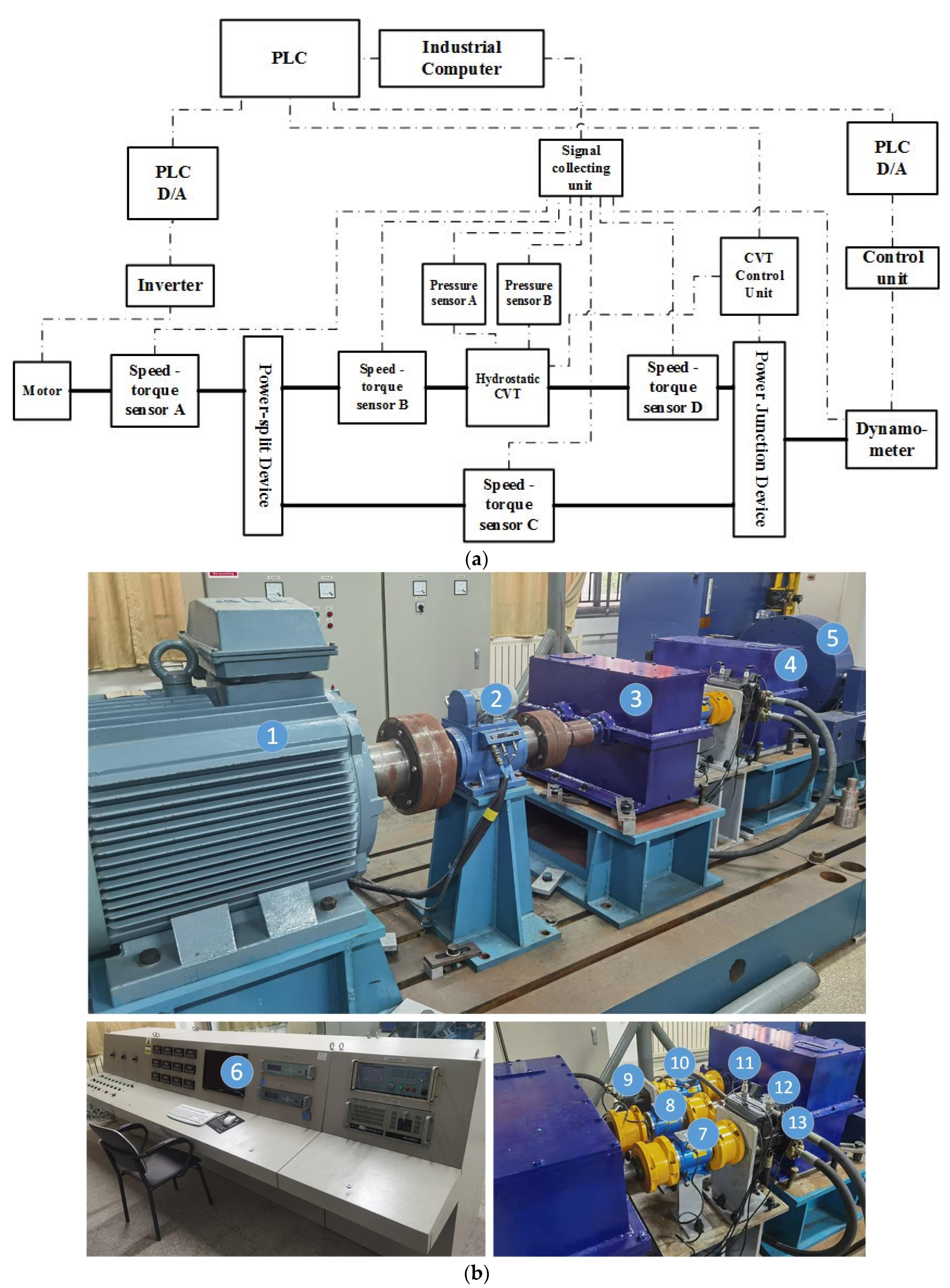
2.1. The Composition of the Test Bench

According to the structural characteristics of HMCVT, the test bench shown in Figure 1 has been developed.
As shown in Figure 1, the test bench includes the AC servo motor of the input power source, the speed-torque sensor A, the tested power split device, the speed-torque sensor B, the tested hydrostatic CVT, the pressure sensor A, the pressure sensor B, the speed-torque sensor D, the speed-torque sensor C, the tested power junction device, the dynamometer of output load, the controller of loading system, PLC D/A module of output, the speed controller, the signal acquisition unit, Industrial Personal Computer (IPC), Programmable Program Controller (PLC), D/A module of the input terminal PLC, and servo motor controller.
The power input uses an AC servo motor as the power source, and the power flow divides into hydraulic power flow and mechanical power flow through the power split device, and then is output after converging through the power junction device, thereby realizing a hydraulic-mechanical composite transmission. The AC servo motor compiles the control program according to the universal characteristic curve of the matching engine. Through the two-level control mode of IPC and PLC, it can simulate the power characteristics of the engine to provide the power source for the test bench. Therefore, it can make the test conditions of the tested object the closest to the actual use conditions.
The load simulation device of the power output end uses a dynamometer to simulate the load resistance of the vehicle running on the road and simulate the power change of the power demand in the vehicle power transmission system. Through the two-level control mode of IPC and PLC, the dynamometer and AC servo motor realize different working modes:
(1)
Constant torque mode: Under the adjustment control of the control system and the control program, the motor is adjusted automatically according to the comparison feedback of the actual measured value of the torque with the given value, by mean of the inverter and the controller according to the given control mode. Eventually, the output torque of the motor is changed to make it maintain at the set value;
(2)
Constant speed mode: Under the adjustment control of the control system and the control program, the motor is adjusted automatically according to the comparison feedback of the actual measured value of the speed with the given value, by mean of the inverter and the controller according to the given control mode. Eventually, the output speed of the motor is changed to make it maintain at the set value;
(3)
Constant power mode: Under the adjustment control of the control system and the control program, the output power of the motor is maintained at a given value.
Through the control program, the test bench can realize the dynamic loading and simulate the actual working conditions of HMCVT and the specified cycle working conditions. According to test schemes, the control system and program can set different values of the AC servo motor speed and the dynamometer torque. The closed-loop control method can fully meet the performance test of the hydrostatic CVT of HMCVT and the proportional test of the mechanical transmission power flow and the hydraulic transmission power flow of HMCVT. The test bench can also be used for the development and verification of the HMCVT control system. Each measurement value and analysis result in the experiment can be displayed, processed, stored, and printed in real-time through the IPC and monitor. Compared with the traditional test bench, this test bench can be used to easily and reliably perform the performance test of the hydraulic transmission unit of HMCVT, saving a lot of test time and cost.

2.2. Test Functions of the Test Bench

This test bench can test and verify the factors affecting HMCVT efficiency which are hydrostatic CVT, mechanical transmission system, and the interaction between them before the prototype of HMCVT. Through testing and verification, the structural scheme is optimized, and finally the structure of the prototype is more reasonable. The technical characteristics are shown in Table 1.
The test and verification functions that can be achieved by the test bench are as follows:
  • Performance test and verification of the power split device;
The transmission performance can be tested by the speed-torque sensor A, the speed-torque sensor B, and the speed-torque sensor C.
  • Performance test and verification of the power junction device;
The transmission performance can be tested by the speed-torque sensor C, the speed-torque sensor D, and the dynamometer.
  • Performance test and verification of hydrostatic CVT;
The transmission performance can be tested by the speed-torque sensor B, the speed-torque sensor D, the pressure sensor A, and the pressure sensor B.
  • Performance test and verification of HMCVT;
The transmission performance can be tested by the speed-torque sensor A and the dynamometer.
  • Test and verification of the HMCVT control system.

3. Method of Multi-Level Test and Verification

Given the structural characteristics of HMCVT, this paper proposes a multi-level test and verification method, which uses a multi-functional test bench to test and verify the components of HMCVT at the early stage of product development. According to the test results, the system theory and simulation model are revised and improved, and finally, the simulation and test verification of HMCVT are carried out. This method mainly solves the problem of testing and verifying the components in the early stage of HMCVT design and development, and then revising and optimizing the system model, thus improving the accuracy of the analysis of the entire transmission system. Finally, through analysis, optimization, and improvement, the designed products achieve the optimal design. By using the modified and improved simulation model, the control system can also be developed and verified more accurately.
As shown in Figure 2, the test and verification process divides into the following three levels.
  • Level 1: Verification of simulation analysis
According to the preliminary design of the HMCVT, a mathematical model and a simulation model are established, and the preliminary design analysis and simulation analyses are carried out, which mainly analyze the structure design and the simulation of the transmission performance. The simulation analyses include the simulation of the transmission system based on AMESim, the dynamic simulation based on ADAMS, and the finite element analysis of ANSYS, mainly for the design and simulation of its structure.
  • Level 2: Test and verification of components performance
The components tested in level 2 mainly include the performance test of the split device, hydrostatic CVT, and the power junction device. According to the test results, the simulation model of level 1 receives feedback and then makes corrections and improvements to improve the accuracy of the simulation model.
The split device and the power junction device mainly realize mechanical transmission through gear transmissions. The test of the transmission performance of the gear transmission includes meshing power loss and oil mixing power loss, which focuses on testing and studying the oil mixing loss of planetary gear transmission. Through the speed-torque sensor A, the speed-torque sensor B, and the speed-torque sensor C, the transmission performance of the power split device in the form of fixed shaft gear transmission can be tested; Through the speed-torque sensor C, the speed-torque sensor D, and the dynamometer, the transmission performance of the power junction device in the form of planetary gear transmission can be tested.
The hydrostatic CVT is a closed hydraulic transmission system mainly composed of a variable displacement pump (VP) and a fixed displacement motor (FM). The hydraulic transmission efficiency is low and unstable compared to the mechanical transmission efficiency, which has a relatively remarkable impact on the transmission efficiency and transmission performance of the HMCVT. Therefore, the focus is on testing its efficiency characteristics. And then the theoretical model and simulation model of the hydrostatic CVT are revised through the test results. Through the speed-torque sensor B, the speed-torque sensor D, the pressure sensor A, and the pressure sensor B, the transmission performance of hydrostatic CVT can be tested.
  • Level 3: Test and verification of HMCVT performance
At this level, the performance test verification of HMCVT is solved. After level 2 of the test and verification, the simulation model is improved and optimized. And then the performance test and verification of the HMCVT transmission system are carried out in this stage, which mainly test the transmission performance of the HMCVT system and the test and analysis of the coupling characteristics of the mechanical and hydraulic transmission. According to the test results, the simulation model is optimized and improved again. The final goal is to achieve consistency and conformity between the simulation model and the actual HMCVT. At the same time, it provides a more accurate simulation model and test verification for the development of the control system. Finally, it provides an accurate reference for the development of HMCVT.

4. Application of Test and Verification

According to the theoretical analysis in the early stage, a preliminary simulation analysis is carried out based on the establishment of the theoretical model and simulation model of HMCVT. Since the HMCVT is a composite transmission system of mechanical transmission and hydraulic transmission, the interaction relationship is relatively complicated. Therefore, the HMCVT transmission system is decomposed to analyze the performance of hydraulic transmission and mechanical transmission separately to analyze its performance more accurately. According to the multi-level verification method, the performance of the hydraulic transmission system is tested and verified using a multi-functional test bench. The parameters of hydrostatic CVT are as shown in Table 2.
The hydrostatic CVT is tested and verified through this method. According to the established theoretical mathematical model, the simulation models are established by Simulink and AMESim, and simulations are carried out to preliminarily verify transmission characteristics. By using the test bench to test the characteristics of hydrostatic CVT, the models are modified and improved according to the test results. Then the simulations are carried out to study its transmission characteristics, and finally, verify the correctness of the results through the test bench.
It can be seen from Figure 3a–g,i, under the usual constant speed, the volumetric efficiency of the hydrostatic CVT decreases with the increase of the working pressure due to the change of the leakage between the sealing surfaces; however, it can be seen from Figure 3a–g,h, the mechanical efficiency of the hydrostatic CVT rises with the increase in pressure, because the higher the pressure, the smaller the proportion of the input torque that is used to overcome the resistance of the components in the hydrostatic CVT. It can be seen from Figure 3a–g,j, The area where the total efficiency of the hydrostatic CVT is the highest, usually under the working condition where the maximum pressure is 40–50%, that is, the corresponding working pressure is generally between 150–210 bar. Therefore, in the design, the maximum pressure of the hydrostatic drive device should only appear in short-term working conditions such as starting, climbing, and overcoming the occasional high load. The pressure in the long-term continuous work should be controlled below the rated pressure. This will not only maintain high efficiency but also help prolong the service life of the components.

5. Discussion

Through the above analysis of the hydrostatic CVT, it is fully demonstrated that the multi-level test and verification method has good feasibility and practicability, which are mainly reflected in the following:
In the first level of simulation verification, based on the separate performance test data of the pump and the motor, the theory, and simulation model of the hydrostatic CVT are established in the HMCVT for analysis and verification, the performance of the hydrostatic CVT is preliminarily analyzed, and the preliminary structural parameters of the HMCVT are established;
In the second level of test and verification, the impact of the performance of the hydrostatic CVT on the HMCVT was tested and verified, and the mathematics and simulation model of the first stage were revised to make it basically consistent with the physical model;
The third level test and verification analyze the coupling characteristics of hydraulic transmission and mechanical transmission. The interaction between it and the power split device and the power junction device affects the transmission performance of the HMCVT, and the mathematical and simulation models are revised and optimized again so that the HMCVT simulation model is the same as the physical model.
The model has been revised several times and verified by the test of transmission efficiency, the error is within ±5%, which has good consistency with the actual physical model. The performance data obtained by a single performance test, the maximum error of the model established is about 25%. Therefore, the model after multiple revisions is more accurate.

6. Conclusions

This paper is mainly to address the method of test and verification and test bench for hydro-mechanical continuously variable transmission. The multi-functional test bench was developed to solve the test and verification of the hydrostatic CVT, mechanical transmission system, and the interaction between them before the prototype of HMCVT; based on the multi-functional test bench, the multi-level test and verification method is proposed to solve that the simulation model is as consistent as possible with the physical prototype, providing an accurate reference for subsequent control method research and control system development. Through the analysis of the hydraulic transmission system, the model that has been improved and optimized many times is more accurate, and its accuracy is within ±5% of the experimental verification result. Therefore, it is shown that the multi-level test and verification method has good feasibility and practicability.
Future work will focus on the research of the coupling characteristics of mechanical transmission and hydraulic transmission and the research of oil mixing loss, to comprehensively and in-depth study the factors affecting the transmission performance of HMCVT. Eventually, providing an accurate reference for subsequent control method research and control system development.

7. Patents

Through this work, the authorized patents are as follows: Electric loading multifunctional test bench for power-dividing hydraulic mechanical composite transmission system and application thereof (Patent No. ZL 201910097716.0, Nation: China); A power junction device with variable characteristic coefficients and application thereof (Patent No. ZL 201910098114.7, Nation: China); Multifunctional test bed for power dividing type hydraulic mechanical composite transmission system, and application of test bed (Patent No. ZL 201910751036.6, Nation: China); Electric loading multifunctional test bench for power-dividing hydraulic-mechanical composite transmission system and application thereof (Patent No.2021/00097, Nation: Republic of South Africa).

Author Contributions

Conceptualization, H.D. and L.W.; methodology, H.D.; software, H.D.; validation, H.D., Z.L. and W.L.; formal analysis, Z.L.; investigation, Z.S.; data curation, Z.S. and W.L.; writing—original draft preparation, H.D.; writing—review and editing, H.D.; visualization, L.W.; supervision, Q.Z.; project administration, L.W.; funding acquisition, Q.Z. All authors have read and agreed to the published version of the manuscript.

Funding

This research was funded by the National Natural Science Foundation of China (51974170), Natural Science Foundation of Shandong Province (ZR2019MEE067), Key R&D Projects of Shandong Province (2019SDZY01), Shandong Provincial Natural Science Foundation (ZR2019BEE069).

Institutional Review Board Statement

Not applicable.

Informed Consent Statement

Not applicable.

Data Availability Statement

Data were curated by the authors and are available upon request.

Conflicts of Interest

The authors declare no conflict of interest.

References

  1. Liebherr-Werk Bischofshofen GmbH. Job Report Wheel Loader L566 XPower. Available online: https://www.liebherr.com/external/products/products-assets/265798/Einsatzbericht%20L%20566%20XPower%20RBS%20Kiesgewinnung%20GmbH.pdf (accessed on 17 September 2021).
  2. ZF Friedrichshafen AG. ZF cPOWER. Available online: https://www.zf.com/products/media/industrial/construction/downloads_1/new/see.think.act._cPower.pdf (accessed on 17 March 2021).
  3. Macor, A.; Rossetti, A. Optimization of hydro-mechanical power split transmissions. Mech. Mach. Theory 2011, 46, 1901–1919. [Google Scholar] [CrossRef]
  4. Wan, L.; Dai, H.; Zeng, Q.; Sun, Z.; Tian, M. Characteristic Analysis and Co-Validation of Hydro-Mechanical Continuously Variable Transmission Based on the Wheel Loader. Appl. Sci. 2020, 10, 5900. [Google Scholar] [CrossRef]
  5. Zhao, J.; Na, J.; Gao, G. Adaptive dynamic programming based robust control of nonlinear systems with unmatched uncertainties. Neurocomputing 2020, 395, 56–65. [Google Scholar] [CrossRef]
  6. Bucolo, M.; Buscarino, A.; Famoso, C.; Fortuna, L.; Frasca, M. Control of imperfect dynamical systems. Nonlinear Dyn. 2019, 98, 2989–2999. [Google Scholar] [CrossRef]
  7. Na, J.; Zhao, J.; Gao, G.; Li, Z. Output-Feedback Robust Control of Uncertain Systems via Online Data-Driven Learning. IEEE Trans. Neural Netw. Learn. Syst. 2021, 32, 2650–2662. [Google Scholar] [CrossRef]
  8. Zhu, Z.; Gao, X.; Cao, L.; Cai, Y.; Pan, D. Research on the shift strategy of HMCVT based on the physical parameters and shift time. Appl. Math. Model. 2016, 40, 6889–6907. [Google Scholar] [CrossRef]
  9. Zhou, Z.; Zhang, J.; Xu, L.; Guo, Z. Modeling and simulation of hydro-mechanical continuously variable transmission system based on Simscape. In Proceedings of the 2015 International Conference on Advanced Mechatronic Systems (ICAMechS), Beijing, China, 22–24 August 2015; pp. 397–401. [Google Scholar]
  10. Xiong, S.; Wilfong, G.; Lumkes, J. Components Sizing and Performance Analysis of Hydro-Mechanical Power Split Transmission Applied to a Wheel Loader. Energies 2019, 12, 1613. [Google Scholar] [CrossRef] [Green Version]
  11. Ince, E.; Guler, M.A. Design and Analysis of a Novel Power-Split Infinitely Variable Power Transmission System. J. Mech. Des. 2019, 141, 8. [Google Scholar] [CrossRef]
  12. Guangwei, C.; Zhili, Z.; Wenchun, Z.; Ting, G. Study on the Tracked Vehicles HMCVT Test-Bed and Its Control & Test System. In Proceedings of the 2006 International Conference on Mechatronics and Automation, Luoyang, China, 25–28 June 2006; pp. 1706–1711. [Google Scholar]
  13. Chang, L.; Zhao, Y.; Lyu, M. Loader power-split transmission system based on a planetary gear set. Adv. Mech. Eng. 2018, 10, 1687814017747735. [Google Scholar]
  14. Liu, F.X.; Wu, W.; Hu, J.B.; Yuan, S.H. Design of multi-range hydro-mechanical transmission using modular method. Mech. Syst. Signal Proc. 2019, 126, 1–20. [Google Scholar] [CrossRef]
  15. Rossetti, A.; Macor, A. Continuous formulation of the layout of a hydromechanical transmission. Mech. Mach. Theory 2019, 133, 545–558. [Google Scholar] [CrossRef]
  16. Zhun, C.; Zhixiong, L.; Fang, D. Research on HMCVT Efficiency Model Based on the Improved SA Algorithm. Math. Probl. Eng. 2019, 2019, 1–10. [Google Scholar] [CrossRef]
  17. Alizadeh, S.M.; Abolpour, R.; Afsharinejad, A.; Dehghani, M. Design of Linear Parameter Varying Controller for Hydrostatic Transmission System (HST). In Proceedings of the 2021 7th International Conference on Control, Instrumentation and Automation (ICCIA), Tabriz, Iran, 23–24 February 2021. [Google Scholar]
  18. Wang, S.L.; Liu, Q.; Wen-Xing, M.A.; Liu, C.B.; Jing, L.I. Simulation Analysis and Experimental Study on Characteristics for Loader Traveling Hydrostatic Transmission System. Hydraul. Pneum. Seals 2019, 39, 34–39. [Google Scholar]
  19. Do, H.T.; Park, H.G.; Ahn, K.K. Application of an adaptive fuzzy sliding mode controller in velocity control of a secondary controlled hydrostatic transmission system. Mechatronics 2014, 24, 1157–1165. [Google Scholar] [CrossRef]
  20. Xia, Y.; Sun, D.; Qin, D.; Zhou, X. Optimisation of the power-cycle hydro-mechanical parameters in a continuously variable transmission designed for agricultural tractors. Biosyst. Eng. 2020, 193, 12–24. [Google Scholar] [CrossRef]
  21. Kumar, R.; Ivantysynova, M.; Williams, K. Study of Energetic Characteristics in Power Split Drives for on Highway Trucks and Wheel Loaders. SAE Tech. Pap. 2007, 116, 227–237. [Google Scholar]
  22. Xiao, M.; Zhao, J.; Wang, Y.; Yang, F.; Kang, J.; Zhang, H. Research on system identification based on hydraulic pump-motor of HMCVT. Eng. Agric. Environ. Food 2019, 12, 420–426. [Google Scholar] [CrossRef]
  23. Jivkov, V.; Draganov, V. Theoretical Study and Experimental Validation of a Hydrostatic Transmission Control for a City Bus Hybrid Driveline with Kinetic Energy Storage. Energies 2018, 11, 2200. [Google Scholar] [CrossRef] [Green Version]
  24. Cheong, K.L. Design and Analysis of Hydraulic Hybrid Passenger Vehicles. Ph.D. Thesis, University of Minnesota, Minneapolis, MN, USA, 2015. [Google Scholar]
  25. Meyer, J.J. The Development of a Power Management Strategy for a Hydraulic Hybrid Passenger Vehicle. Ph.D. Thesis, University of Minnesota, Minneapolis, MN, USA, 2014. [Google Scholar]
  26. Concli, F.; Conrado, E.; Gorla, C. Analysis of power losses in an industrial planetary speed reducer: Measurements and computational fluid dynamics calculations. Proc. Inst. Mech. Eng. Part J J. Eng. Tribol. 2013, 228, 11–21. [Google Scholar] [CrossRef]
  27. Concli, F.; Gorla, C. Analysis of the oil squeezing power losses of a spur gear pair by mean of CFD simulations. In Proceedings of the ASME 2012 11th Biennial Conference on Engineering Systems Design and Analysis, ESDA 2012, Nantes, France, 2–4 July 2012; pp. 177–184. [Google Scholar]
  28. Nutakor, C.; Montonen, J.; Nerg, J.; Heikkinen, J.; Sopanen, J.; Pyrhönen, J. Development and validation of an integrated planetary gear set permanent magnet electric motor power loss model. Tribol. Int. 2018, 124, 34–45. [Google Scholar] [CrossRef]
  29. Kahraman, A.; Hilty, D.R.; Singh, A. An experimental investigation of spin power losses of a planetary gear set. Mech. Mach. Theory 2015, 86, 48–61. [Google Scholar] [CrossRef]
Figure 1. HMCVT multi-function test bench structure and physical diagram: (a) HMCVT multi-function test bench structure diagram; (b) HMCVT multifunctional test bench. 1 AC servo motor; 2 Speed-torque sensor A; 3 Power split device; 4 Power junction device; 5 Dynamometer; 6 Control platform; 7 Speed-torque sensor B; 8 Speed-torque sensor C; 9 Fixed displacement motor (FM); 10 Speed-torque sensor D; 11 Pressure sensor A; 12 Pressure sensor B; 13 Variable displacement pump (VP).
Machines 09 00358 g001
Figure 2. Process of multi-level test and verification.
Machines 09 00358 g002
Figure 3. Analysis results of hydrostatic CVT: (a) T M = 175   N · m ; (b) T M = 150   N · m ; (c) T M = 125   N · m ; (d) T M = 100   N · m ; (e) T M = 75   N · m ; (f) T M = 50   N · m ; (g) T M = 25   N · m ; (h) Mechanical efficiency η m ; (i) Volumetric efficiency η v ; (j) Total efficiency η t .
Machines 09 00358 g003aMachines 09 00358 g003b
Table 1. The technical characteristics.
SensorRangeAccuracy
Speed-torque A4000 rpm/1000 N∙m±0.2%
Speed-torque B4000 rpm/500 N∙m±0.2%
Speed-torque C4000 rpm/1000 N∙m±0.2%
Speed-torque D4000 rpm/500 N∙m±0.2%
Pressure sensor A0~450 bar0.1%FS
Pressure sensor B0~450 bar0.1%FS
Table 2. The parameters of hydrostatic CVT.
ParametersValue
VP speed n P 1400 r/min
FM torque T M 25~175 N∙m
VP displacement−28~28 mL/r
i CVT −1~1
VP Maximum displacement28 mL/r
FM displacement28 mL/r
Maximum pressure420 bar
Publisher’s Note: MDPI stays neutral with regard to jurisdictional claims in published maps and institutional affiliations.

