1. Introduction
In recent years, with the development of high-performance semiconductor devices such as SiC and GaN, power conversion devices have become more efficient, and low-loss devices with conversion efficiencies of over 99% have been developed [
1]. For the thermal design and evaluation of such devices, it is important to measure the power loss of the device with high accuracy. Power loss is typically calculated by using a power meter to measure input and output power and calculating the difference between them [
2,
3]. However, due to the high efficiency of power conversion devices, the ratio of power loss to the measured power becomes very small, which increases the error in the measurement equipment and prevents highly accurate measurement results from being obtained.
This problem can be solved by using a calorimetric method to derive the power loss from the amount of heat released from the power conversion device [
4]. This method measures the amount of heat emitted when the power conversion device (DUT: device under test) to be measured is driven inside a thermostatic chamber through a medium such as air or water. This reduces the error in the measurement equipment that occurs when power loss is measured using a power meter. However, the calorimetric method requires a heat exchanger and a flow meter, which makes the system configuration complex and expensive. In the calorimetry method, if there is a temperature difference between the internal and ambient temperatures of the thermostatic chamber, heat leakage from the inside of the chamber occurs, and the measurement accuracy decreases.
Therefore, a calorimetric measurement system using a Peltier device has been proposed in a previous study [
5]. A Peltier device is a device that dissipates heat on one side and absorbs heat on the other side by passing current through it, and high-precision temperature control can be achieved by controlling the current flowing through the device. By using the Peltier device in the calorimetric measurement system, a heat exchanger and a flow meter are not necessary, and the system can be configured simply and inexpensively. In addition, the Peltier device can be used to control the internal temperature of the chamber to follow the ambient temperature, thereby reducing heat leakage from inside the chamber.
The Peltier-device-based system is a nonlinear control system, and it is difficult to apply classical control theory to it. In a previous study [
5], a control system with a robust right-collinear factorization based on operator theory was proposed to solve this problem. There are several control methods such as sliding mode control [
6] and adaptive control [
7,
8], but in this paper, the control system is designed based on operator theory as in the previous study. Operator theory [
9,
10,
11,
12,
13,
14,
15,
16,
17] restricts the space of input signals and the output space, so it can be applied not only to linear control systems but also to nonlinear control systems. There are three advantages of using operator theory: first, there is no need to use transfer functions; second, robust stability analysis can be performed even when nonlinear elements are included; and third, it can be extended to multiple input–output systems. The references [
9,
10,
11,
12,
13,
14,
15,
16,
17] are papers on this theory, in which a nonlinear control system is designed based on operator theory. However, the heat transfer inside the Peltier device was not taken into account in the calorimetric measurement system proposed in the previous research. Since the Peltier device has a high temperature on one side and a low temperature on the other side, there is heat transfer inside the device, which affects the temperature control. The thermal conductivity is a coefficient that represents this heat transfer. In the previous study, thermal conductivity was treated as a constant value regardless of the ambient conditions. However, the thermal conductivity is known to vary depending on the physical properties of the material and the temperature [
18,
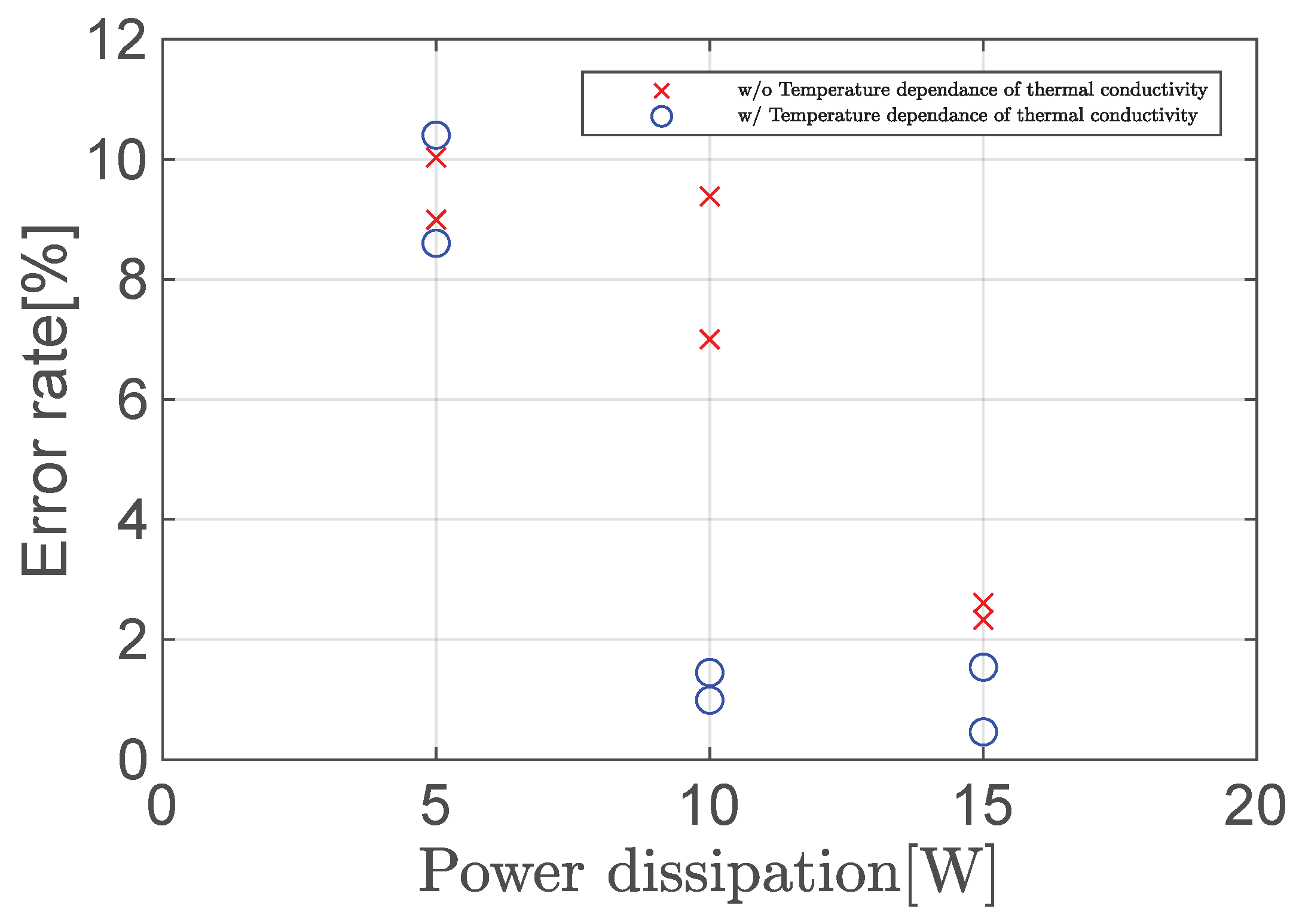
19]. Therefore, in this article, a control system considering the temperature dependence of thermal conductivity is designed based on operator theory. The effectiveness of the proposed system is verified in terms of two aspects, measurement accuracy and measurement time, by comparing it with a previous study that did not consider the temperature dependence of thermal conductivity, through simulation and experiment.
The contents of this paper are as follows. Firstly, the structure and measurement principles of the calorimetric measurement system using the Peltier device are explained, and the modeling and control system design are shown in
Section 2. Then, the simulation and experimental results are presented in
Section 3. Finally, the conclusion is given in
Section 4.
2. Presentation of the System and Control System Design
In this section, a heat measurement system considering the temperature dependence of the thermal conductivity in a Peltier device is described.
Section 2.1 describes the Peltier device.
Section 2.2 describes the heat measurement system using the Peltier device.
Section 2.3 describes the modeling of the calorimetric system,
Section 2.4 explains the temperature dependence of the thermal conductivity, and
Section 2.5 shows the design of the nonlinear feedback control system based on operator theory. Finally,
Section 2.6 describes the experimental system.
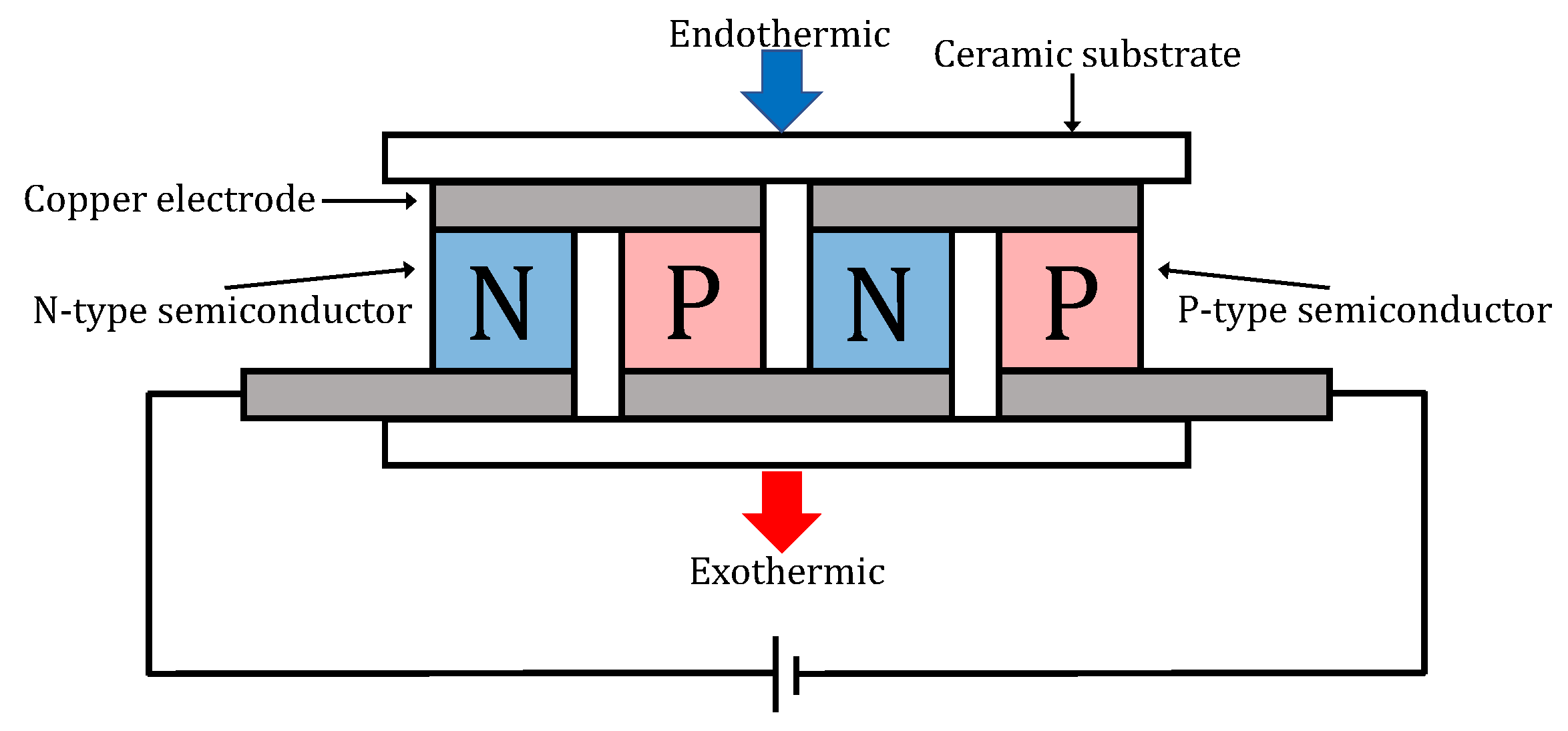
2.1. The Structure of the Peltier Device
The structure of the Peltier device is shown in
Figure 1. Inside the Peltier device, N-type and P-type semiconductors are arranged alternately and connected in series by copper electrodes. When the current is applied to the device, a temperature difference is generated on both sides of the device, causing an endothermic reaction on the low temperature side and an exothermic reaction on the high temperature side. By changing the direction of the current flowing through the device, the heat-absorbing and heat-dissipating surfaces can be switched. When the heat generated on the heat-dissipating surface is not sufficiently exhausted, the heat on the heat-dissipating side conducts heat through the device to the heat-absorbing side, and the cooling capacity of the device is reduced. To prevent such a phenomenon, the heat on the heat-dissipating side must be cooled by forced air cooling using a heat sink and fan or by water cooling. The amount of endothermic energy of the Peltier device
(W) is shown in Equation (
1) and the amount of exothermic energy of the Peltier device
(W) is shown in Equation (
2) [
20].
The parameters used in Equations (
1) and (
2) are shown in
Table 1.
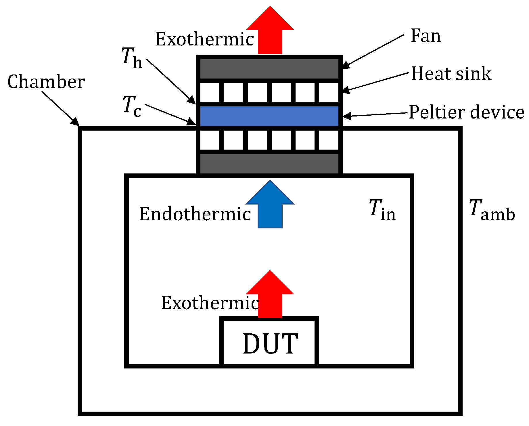
2.2. Principles of the Calorimetric System Using the Peltier Device
The structure of the calorimetric system using the Peltier device is shown in
Figure 2. The entire system is made of styrofoam, with the Peltier device, temperature sensors, heat sinks, and fans installed. If there is a difference between the temperature inside the chamber
and the ambient temperature
, the measurement accuracy will be degraded due to heat leakage
inside the chamber.
is shown as [
21]
where
is the thermal resistance of the chamber wall.
When the DUT is driven, the temperature inside the container rises. This rise in temperature is absorbed by the Peltier device by passing a current through it. When
and
become equal, all the heat released from the DUT is absorbed by the Peltier device. The power loss of the DUT,
, can be obtained from the heat absorption of the Peltier device Equation (
1) as follows [
5]:
where
is the power dissipation of the cold-side fan motor.
2.3. Modeling of the System
The system is modeled according to Newton’s cooling law and Fourier’s law. Newton’s cooling law is the heat transfer between a solid and a fluid and is given by Equation (
5) [
5]. Fourier’s law pertains to heat conduction in solids and is given by Equation (
6) [
5]. The parameters used in Equations (
5) and (
6) are shown in
Table 2.
In addition, thermal resistance and heat capacity are determined by a heat transfer phenomenon. The heat transfer phenomenon is divided into heat conduction, heat transfer, and radiation. Heat conduction is the propagation of thermal energy in a solid, and thermal resistance is given by Equation (
7) using the heat transfer area
A, length
L (m), and thermal conductivity
(W/mK) [
5].
Heat transfer is the heat transfer between the solid and the fluid, and the heat resistance is given by Equation (
8) using the surface area
S and the heat transfer coefficient
h .
Radiation is the transfer of heat energy by electromagnetic waves. In the case of radiation from surface A with surface temperature
(K) to surface B with surface temperature
(K), the thermal resistance is given by Equation (
9) using the Stefan–Boltzmann constant
and surface emissivity
f [
5].
The heat capacity
C (J/K) is the amount of heat required to raise the temperature of an object by 1 (K). It is given by Equation (
10) using the volume
V, density
, and specific heat
of the object [
5].
The differential equations for the heat conduction of the temperature
of the DUT, the temperature
inside the system container, and the temperatures
and
of the cold side and hot side of the Peltier device are as follows [
5]:
where the direction of heating inside the chamber is defined as positive current.
is the thermal resistance of the Peltier device and is given by the structure of the Peltier device as follows:
The parameters of the model are shown in
Table 3.
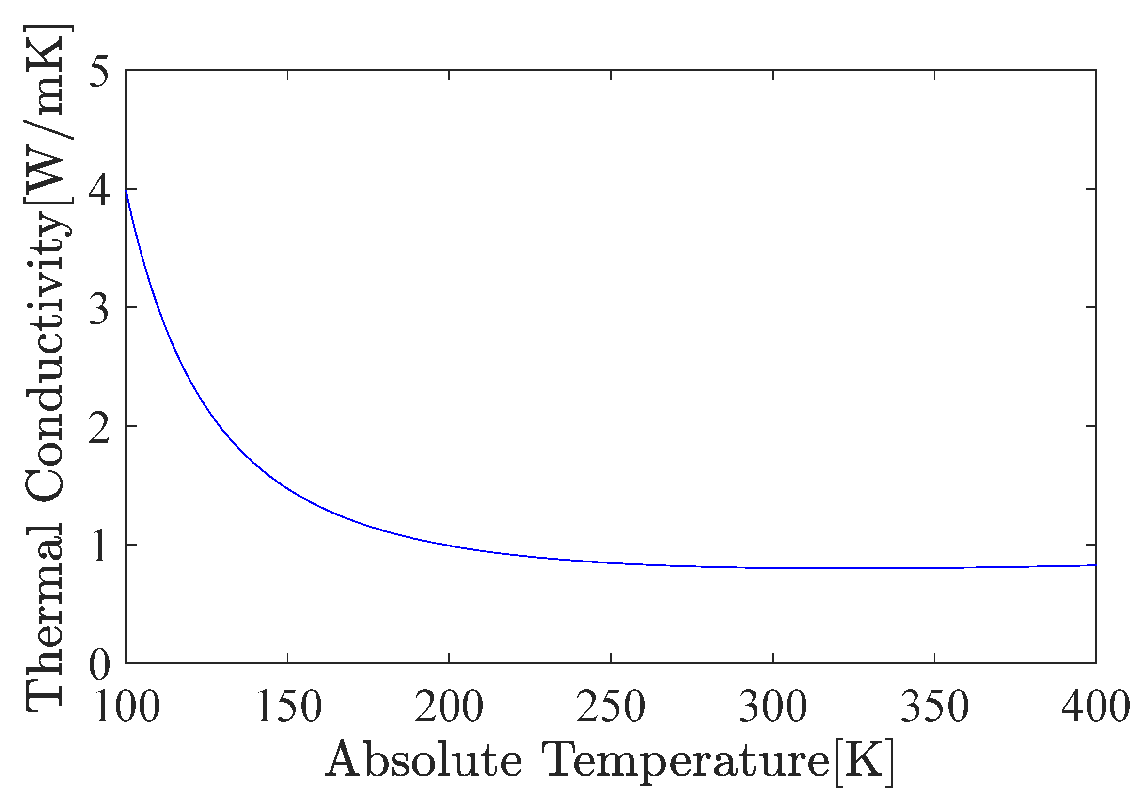
2.4. Temperature Dependence of Thermal Conductivity
Thermal conductivity can be divided into electronic thermal conductivity
and lattice thermal conductivity
, as shown in Equation (
16) [
19].
The electronic thermal conductivity
is the energy transfer based on conduction electrons and is expressed according to Wiedemann–Franz’s law as follows:
where
L (
) is the Lorentz constant,
(
) is the electrical conductivity of the material, and
T (
) is the absolute temperature. Because of the inclusion of absolute temperature in Equation (
17), the electronic thermal conductivity varies with temperature.
Lattice heat conduction is the heat conduction caused by the lattice vibrations of atoms and molecules in a crystal. The atoms and molecules in a crystal undergo thermal vibrations as the temperature rises, and since these vibrations are complex and difficult to schematize, the concept of phonons is introduced. By introducing the concept of phonons, thermal conductivity can be expressed using the mean free path of phonons. The mean free path of a phonon is shown as
where
T (
) is absolute temperature and
(
) is Debye temperature. Debye temperature is a physical property that converts Debye frequency into a temperature dimension, and Debye frequency is a physical property that contributes to the specific heat of a solid. Debye temperature
(
) and Debye frequency
(1/s) are given in Equations (
19) and (
20), respectively.
The mean free path in Equation (
18) is used to express the lattice thermal conductivity as follows:
Since Equation (
21) includes absolute temperature, the lattice thermal conductivity varies with temperature.
From Equations (
16), (
17), and (
21), the thermal conductivity can be expressed as follows:
The values of each parameter in the Peltier device are shown in
Table 4.
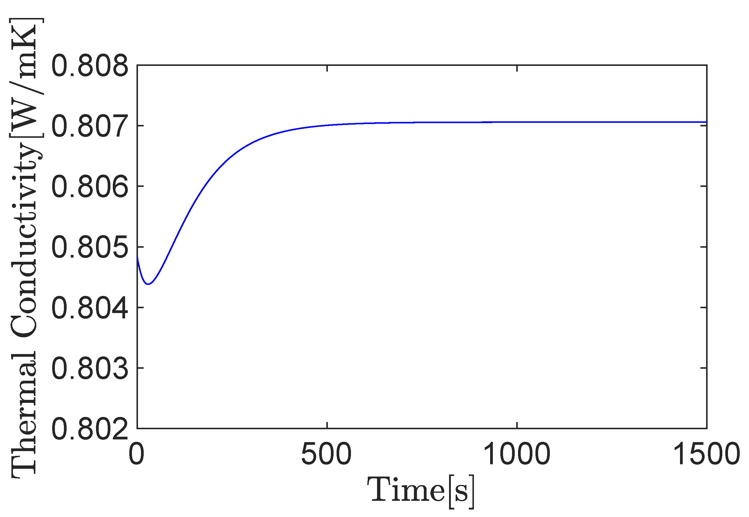
The temperature dependence of the thermal conductivity in the Peltier device is shown in
Figure 3.
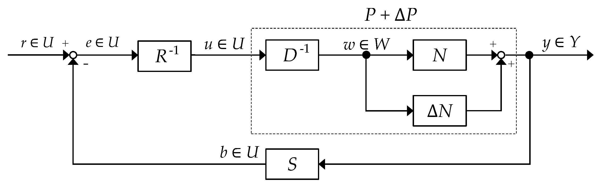
2.5. Operator-Based Nonlinear Control Feedback System Design
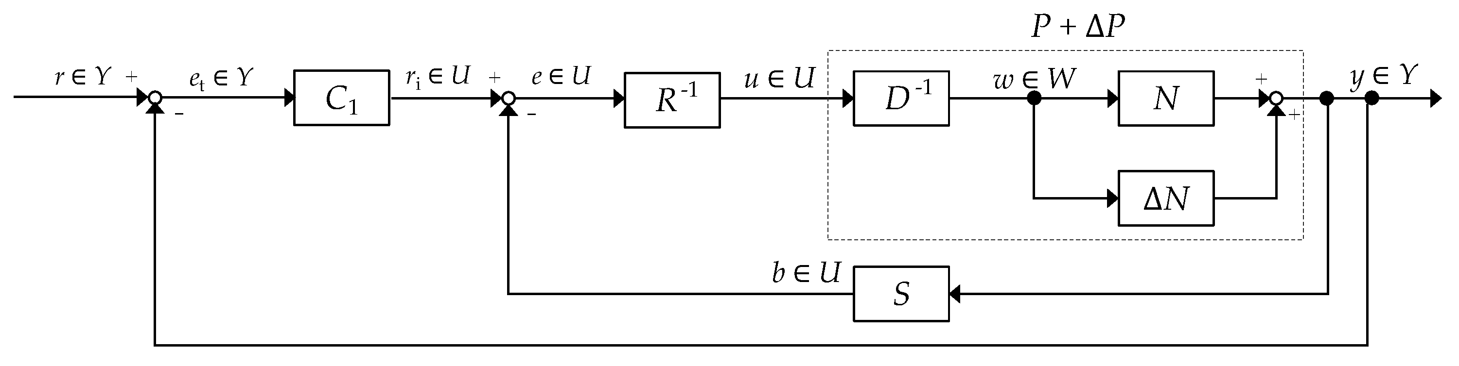
Figure 4 shows the proposed nonlinear feedback control system using robust right coprime factorization based on operator theory. The detailed information about operator theory is written in [
9,
10,
11,
12,
13,
14,
15,
16,
17].
The given plant operator
is said to have a right factorization if there exist a linear space
W and two stable operators
and
such that
D is invertible from
U to
W and
on
U. Such a factorization of
P is denoted as
, and the space
W is called a quasi-state space of
P. In addition,
P is said to be a right coprime factorization if there exist two stable operators
and
that satisfy the Bezout identity
where
R is invertible and
means
M is unimodular.
The nominal plant
P is shown as
where the input signal
is the flowing current through the Peltier device and the output signal
of the plant is the temperature
in the system chamber.
The right factorization of the nominal plant is performed and
N,
D designed to satisfy
are shown as
where
N is stable and
D is stable and invertible.
S and
R are designed to satisfy the Bezout identity in Equation (
23) as follows:
where
S is stable and
R is stable and invertible.
The unmodeled uncertainties and noise are regarded as bounded perturbation
, and the overall plant
can be described as
Then, the right factorization of the overall plant
can be redescribed by using
, which is the numerator of the coprime factorization presentation of
:
The right factorization of
is as follows:
where
in respect of the uncertainties and noise is bounded and operators
are stable.
When Equation (
23) and
are satisfied, the robust stability of the plant with uncertainty
can be guaranteed [
9,
10,
11,
12,
13,
14,
15,
16,
17].
The block diagram of the entire calorimetric system is shown in
Figure 5.
is a controller that compensates for the tracking of the target value of the temperature in the chamber, and the PI controller is used. The output of the controller is shown as
where
is the proportional gain and
is the integral gain.
2.6. Experimental System
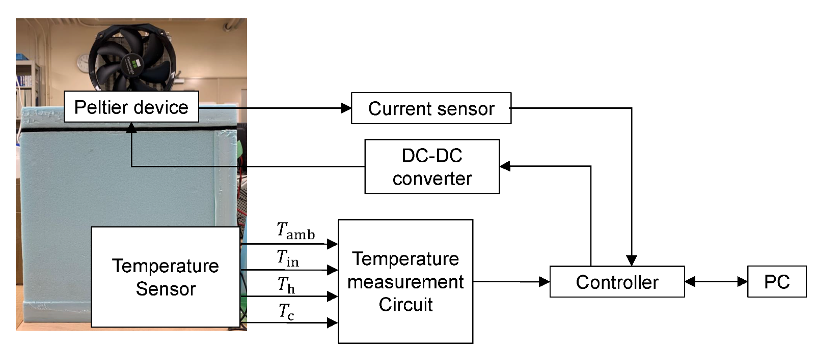
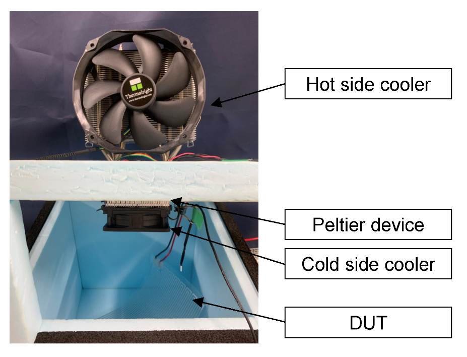
Figure 6 shows the experimental system and
Figure 7 shows the inside of the chamber. The procedure of the experiment is to operate the aluminum resistor used as a substitute for the DUT to achieve the desired power consumption in the chamber. The power input to the aluminum resistor is supplied from the DC power supply, and the DC power supply is adjusted to match the desired power, such as 5, 10, and 15 (W). The temperature inside the chamber rises due to the amount of heat released from the aluminum resistance. At this time, a current is applied to the Peltier device to cool the chamber so that the temperature inside the chamber follows the ambient temperature. When the temperature inside the chamber matches the ambient temperature, the amount of heat generated by the aluminum resistor is calculated using Equation (
4) from the temperature of both sides of the Peltier device and the current applied to the Peltier device.
The materials used in the calorimetric system are shown in
Table 5.


