Article

Kinematic Analysis of a Gear-Driven Rotary Planting Mechanism for a Six-Row Self-Propelled Onion Transplanter

1
Department of Agricultural Machinery Engineering, Graduate School, Chungnam National University, Daejeon 31134, Korea
2
Department of Smart Agricultural Systems, Graduate School, Chungnam National University, Daejeon 31134, Korea
3
TYM Co., Ltd., Iksan 54576, Korea
4
National Institute of Agricultural Science, RDA, Jeonju 54875, Korea
*
Author to whom correspondence should be addressed.
Machines 2021, 9(9), 183; https://doi.org/10.3390/machines9090183
Submission received: 16 July 2021 / Revised: 18 August 2021 / Accepted: 24 August 2021 / Published: 30 August 2021
(This article belongs to the Section Machine Design and Theory)

Abstract

:
The purpose of this study was to develop a kinematic model of a gear-driven rotary planting mechanism for a self-propelled onion transplanter. The kinematic model was simulated using a commercial mechanical design and a simulation software package, and was validated through an on-site performance test. Torque and acceleration sensors were installed with an input power shaft and hopper jaws, respectively. Through kinematic analysis and simulation, the appropriate length combinations for primary, connecting, and planting arm were determined as 90, 70, and 190 mm, respectively. The diameters of the driver, driven, and idler gears in the primary arm were 56, 48, and 28 mm, respectively. For the secondary link, the diameters of the driver, idler, and driven gears were 28, 28, and 56 mm, respectively. The length of the planting hopper was selected as 190 mm and remained constant during the kinematic analysis. The maximum magnitude of the velocity and acceleration of the planting mechanism were determined as 1032 mm/s and 6501 mm/s2, respectively. The power consumption was measured as 35.4 W at 60 rpm. The single- and double-unit assembly of the studied rotary planting mechanism can transplant 60 and 120 seedlings/min, respectively.

1. Introduction

Onion (Allium cepa L.) is one of the most popular vegetables, used throughout the year in all manner of condiments and in all households, especially in Asian countries. It contains several nutritional components such as carbohydrates, proteins, vitamin C, B6, folic acid, sugars (glucose, fructose, galactose, and arabinose), minerals (Ca, Fe, S), flavonoids, antioxidants, and polyphenols, all of which function as alternative medicines and as methods for promoting health [1,2]. Onions can be consumed in a raw or cooked condition. Yellow and green onions are often used as ingredients in traditional cuisine in south-east Asia. Hence, the demand for onions is high all over the world. In 1996, onion cultivation occupied 2.4 million ha of land globally, which increased to 4.9 million ha by 2016; during this period, onion production increased from 60 to 90 million tons [3]. Despite this, onion cultivation rates are decreasing in many countries. For instance, onion production in Korea declined by 426,223 tons (26.7%) in 2020 compared to 2019 [4]. The primary causes of declining onion production are a scarcity of farm labor and the lack of mechanization in transplanting operations [5]. Mechanized onion transplanters are therefore required to solve issues in production and help both small landholders and older, more established farmers.
Mechanized transplanting approaches for seedlings and plants have become popular in recent years since they allow minimizing production costs. Moreover, the use of semi-automatic transplanters allows more homogenous distribution of seedlings [6], which is typically inconsistent in manual transplanting due to human error [7]. However, laborers are still needed to regulate a transplanter’s movement and to feed seedlings into its transplanting mechanism [2]. In order to solve these challenges, various studies have focused on automatic and robotic vegetable transplantation. Both automatic and semi-automatic onion transplanters have been developed over the past two decades. Automatic transplanters are able to feed seedlings into the hopper of a planting device via mechanically designed self-propelled mechanisms, whereas for semi-automatic transplanters, farmers must manually feed seedlings into the planting device [8]. The planting mechanism is the main core component of an automatic onion transplanter that determines the transplanting efficiency [9]. Wheel-, rotary-, and linkage-type planting mechanisms are mainly utilized in automatic onion transplanters [10]. The main working principle of all these planting mechanisms is to vertically deposit onion seedlings into the soil at a certain depth and planting interval. The complete process can also be described as punching through the mulch, creating a minimum diameter cavity, implanting the seedling, covering it with the soil, and maintaining a certain degree of uprightness of the seedling [11].
Several types of planting mechanism have been established by different researchers, including pocket-type [12], cup- or bucket-type [13], split cone cup [14], and disc-type [15]. Pocket-type mechanisms are used for bare-root seedlings, and rotary cup-type mechanisms are used in transplanters for plugs [16]. However, there is still a dearth of mechanically operated transplantation devices globally. Overall, the transplanting efficiency depends on the type of transplanting mechanism used in a given transplanter [17]. These limitations in transplanting efficiency occur due to the non-vertical deposition of a seedling into the soil as well as the creation of a wide transplanting hole diameter by some vegetable transplanters [18].
The operating characteristics of a machine have to be tested in order to optimally design and construct an agricultural machine. Kinematic analysis plays a key role in optimizing design by minimizing structural complexity [19]. Many studies have conducted kinematic analyses to improve the position, speed, and acceleration of planting mechanisms [20]. A kinematics model was established based on displacement and orientation information matrices with an optimization program for the pot seedling transplanting mechanism [21]. The analysis showed that the main structural parameters, such as the length of the seedling jaws and angle of the planting arms, were affecting the shape of the transplanting trajectory. Major design parameters for a gear-driven hopper-type dibbling mechanism was established using kinematic analysis [22], to accomplish the requisite seeding intervals and depths. The analytical results were used to optimize the arm lengths and gear diameters. Kinematic analysis with virtual model simulation of a clamp-type pepper seedling picking device was proposed to find out the dimensions of the device and the effect of gripper [23]. In order to achieve ideal parameters for the transplanting mechanism, a kinematic model was used to improve the seedling rate and reduce the mulch injury rate [24].
When developing an automatic onion transplanting mechanism, it is essential to design an authentic planting mechanism that can implant onion seedlings by punching the soil, creating a narrow diameter cave, vertically depositing said seedlings into the soil, and covering and compacting the soil. In this study, a gear-driven rotary-type planting mechanism was designed for a self-propelled onion transplanter. Therefore, the objectives of this study were (i) to develop a kinematic model to find out the appropriate link combinations for the planting mechanism, and (ii) to evaluate the virtual simulation and field test of the planting mechanism for optimized transplanting kinematic characteristics (i.e., position, velocity, and acceleration), for improved working speed and successful transplanting rate for the self-propelled onion transplanter.

2. Materials and Methods

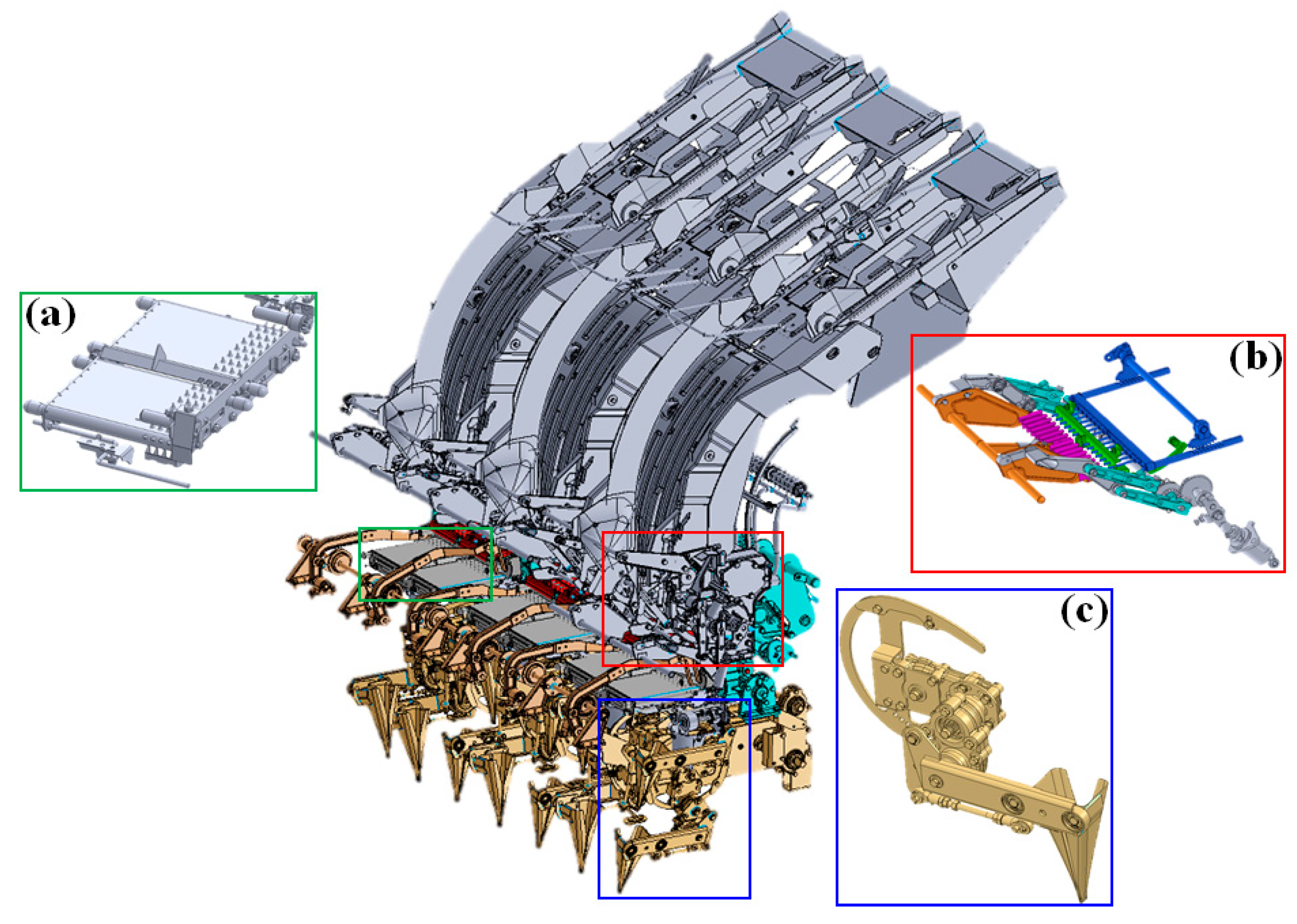
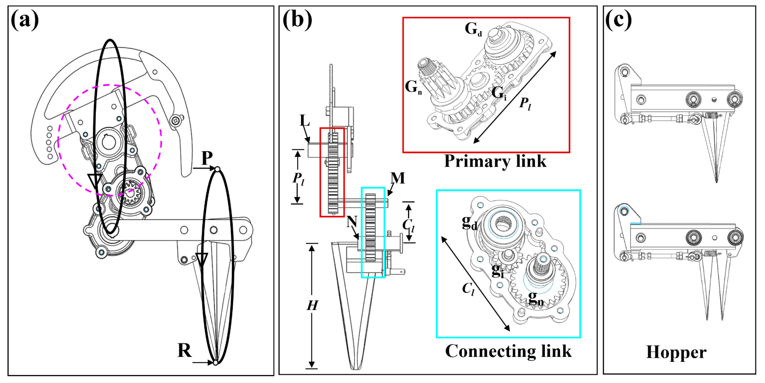
2.1. Overall Structure and Working Principle of Onion Transplanter

Figure 1 illustrates a self-propelled riding-type 6-row onion transplanter. As with most vegetable transplanters, an onion transplanter consists of three mechanisms: an extraction mechanism (seedling picking), a conveyor mechanism (seedling supply), and a planting mechanism (seedling planting) [23]. A pushpin-type seedling extraction mechanism was used to extract the onion seedlings from the growing cell tray.
The picking mechanism is comprised of a pushpin mechanism assembly and a seedling carrying assembly. A 6-row onion transplanter includes three separate units of seedling pushing mechanisms and carrying assemblies. All these units are synchronized together so that each unit can supply 14 seedlings per cycle to the conveyor mechanism. Therefore, current transplanter is able to extract and supply 42 seedlings to 6 separated conveyors. On the other hand, each conveyor mechanism receives 7 seedlings per cycle, which are further fed into the hopper of the rotary planting mechanism.
As shown in Figure 2, the rotary planting mechanism comprises four components: the primary link (Pl), the connecting link (Cl), the extended link, and the planting hopper (H). The primary link is a combination of a two-stage gear train mechanism, where Gd, Gi, and Gn act as drive gears, idler gears, and driven gears, respectively. The gear ratio between the drive gear, idler gear, and the driven gear is 1:1.2:2. A round bar shaft M helps to connect the primary and connecting links of the rotary planting mechanism. Similarly, the connecting link consists of three gears—drive gear, idler gear, and driven gear—which are shown in in Figure 2 as gd, gi, and gn.
The extended lever link acts as a junction between the connecting link and the hopper and holds the cam and follower assembly to execute the opening and closing operation of the hopper jaws during the transferring and implanting of a seedling. The planting hopper collects the seedlings at position P and the cam nose remains detached from the follower; as a result, the hopper jaws remain closed during seedling transfer. When the hopper reaches position R, the cam nose strikes the follower, and the hopper jaws undergo an opening operation. This operation occurs continuously to ensure successful transplantation of the seedlings. Finally, two kinds of operation occur for successful onion transplantation, i.e., picking the seedling and punching it into the soil at the required depth in an upright position.
During the continuous process of planting, the primary and secondary links rotate in opposite directions to each other; if the primary link rotates in a clockwise direction, then the connecting secondary link rotates in a counterclockwise direction. This is the way the hopper jaws move around positions P and R to pick up and place the seedlings in order to create a specific motion trajectory pathway, as shown in Figure 2. One seedling can be transplanted for one complete rotation cycle of a single-unit rotary planting mechanism. Another identical unit of the rotary planting mechanism is thus added to the same power drive line.

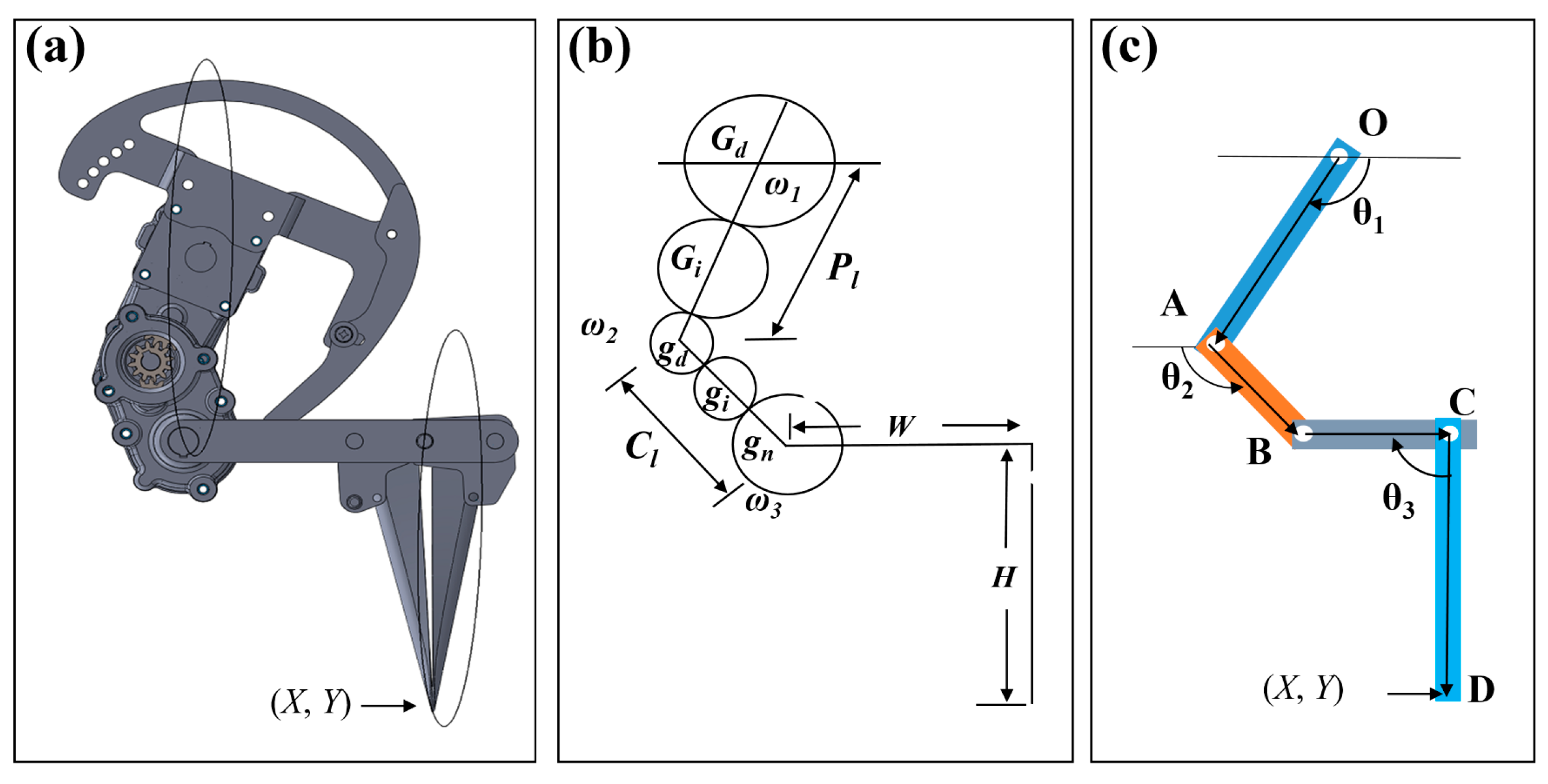
2.2. Vector-Loop Modeling of the Rotary Planting Mechanism

The primary, connecting, and hopper components of the rotary planting mechanism establish a 3R open-chain mechanism. Table 1 indicates the variable notations, definitions, and measurement units used in this study.
Kinematic analysis of the mechanism can be modeled by creating a vector loop of OAB, as shown in Figure 3, and expressed as Equation (1):
O A + A B O B = 0
where O is the center of rotation, A is the linked point between the primary arm and the connecting arm, and B is the joint point between the connecting link and the hopper. By using a vector loop of (1), the X and Y components of position equations of the end point (x, y) can be derived as Equations (2) and (3):
O A c o s θ 1 + A B c o s θ 2 O B c o s θ 3 = 0
O A s i n θ 1 + A B s i n θ 2 O B s i n θ 3 = 0
The primary and connecting links of a planting mechanism comprise different gear train mechanisms. The whole transplanting mechanism, including seedling picking, supplying, and planting, is synchronized by a unit power drive line. Therefore, the smooth deposition of onion seedlings requires the same input and output rpm for the primary link and the planting hopper. Different gear train ratios shown in Table 2 of primary and connecting links were assumed, and the ratio between the driver and the driven gears was calculated by Equation (4) as below:
G . R = T 2 T 1 = d 2 d 1
The gear contact ratio is another important feature of gear linkage mechanisms for maximum operational efficiency of the gear train. For smooth meshing operation of the spur gears, it is recommended that the gear contact ratio should be greater than 1.4 and less than 2 [25]. Gear contact ratio can be measured using Equation (5) [26], as below:
C R = ( N 1 + 2 ) 2 ( N 1 c o s α ) 2 + ( N 2 + 2 ) 2 ( N 2 c o s α ) 2 ( N 1 + N 2 ) s i n α 2 π c o s α
where N1 and N2 are the total number of teeth of each of the two meshing gears.
The pressure angle and the module of the gear were considered as 20° and 2, respectively. Each gear was designed using SolidWorks software, and the diameters required to calculate the length of the primary and connecting links were measured accordingly. Gear train combination and ratios were used to determine the lengths of the primary and connecting links of the planting mechanism using Equations (6) and (7) [22] as:
P l   = 0.5 G d + G i + 0.5   G n
C l   = 0.5   g d + g i + 0.5   g n

2.2.1. Position Analysis

The vertical movement of the hopper is a necessary condition for the successful transplantation of a seedling. If the position vector values OA, AB, and OB in Equations (2) and (3) are substituted for Pl, Cl, and H, respectively, then the Equations (8) and (9) can be calculated as:
P l c o s θ 1 + C l c o s θ 2 = X
P l s i n θ 1 + C l s i n θ 2 H = Y
As such, the Equations (8) and (9) satisfy the Cartesian coordinates of the planting mechanism hopper. The motion trajectory pathway of the position in both X and Y directions can be found using these equations.

2.2.2. Velocity and Acceleration

By taking the 1st and 2nd time derivatives of the position equations, velocity and acceleration equations for each point of the rotary planting mechanism can be derived, and the horizontal velocity and acceleration of the planting mechanism are given by Equations (10) and (11):
P l sin θ 1 ω 1 C l s i n θ 2 ω 2 = v x
P l ω 1 2   c o s θ 1 ω 1 C l ω 2 2   c o s θ 2 ω 2 = a x
Similarly, the vertical velocity and acceleration of the planting mechanism are given by Equations (12) and (13):
P l c o s θ 1 ω 1 + C l   c o s θ 2 ω 2 = v y
P l ω 1 2   s i n   θ 1 ω 1 C l ω 2 2   s i n θ 2 ω 2 = a y
Then, the magnitude of the velocity and acceleration of the planting hopper is given as Equations (14) and (15):
v m   = v x 2 + v y 2
a m   = a x 2 + a y 2
The input required power (p) to drive the planting mechanism can described as a function of velocity (vm), acceleration (am), and mass (m). The power requirement formula of the planting mechanism is given as Equation (16):
p = m a m v m

2.2.3. Simulation of the Rotary Planting Mechanism

The planting mechanism is the primary component of this device and plays an important role in the successful transplantation of seedlings. Therefore, a number of parameters and features of the mechanism need to be evaluated and optimized, as per required standards. Computational simulation of the mechanism is a convenient way of standardizing the parameters compared to conventional methods, which are complicated and time consuming. The 3D model of the rotary planting mechanism was designed, and the working condition was animated and simulated using a commercial software package (SOLIDWORKS 2018, Dassault Systems SolidWorks Corp., Waltham, MA, USA). Table 3 represents the number of parameters considered for the simulation of the rotary planting mechanism.

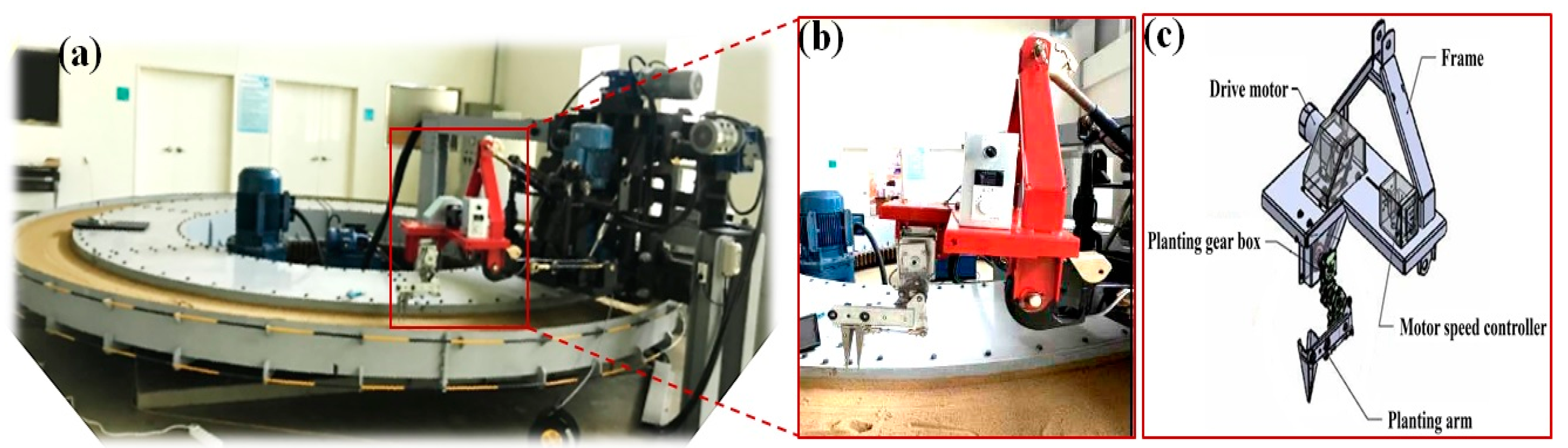
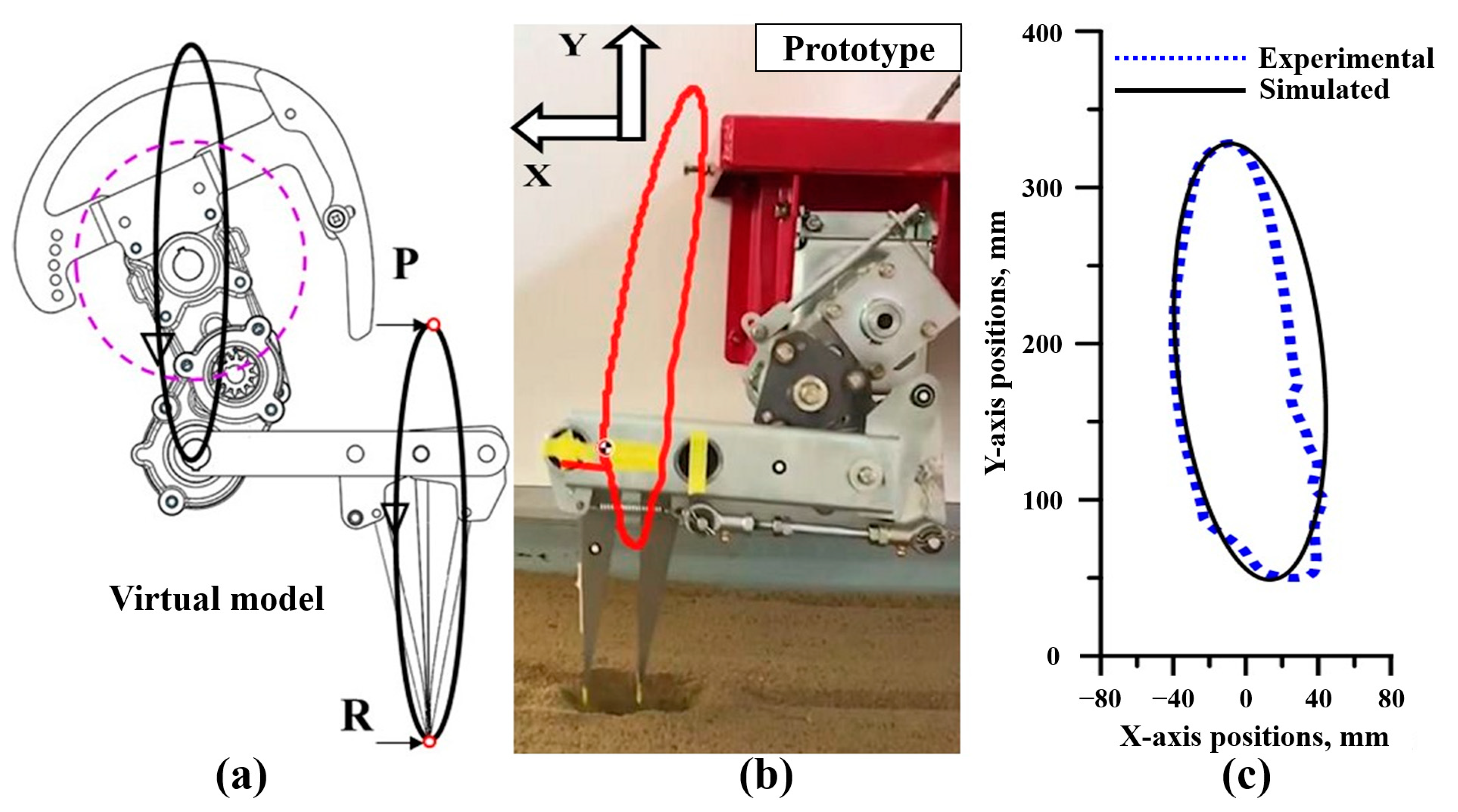
2.3. Validation of Planting Mechanism

A field experiment was conducted at the Rural Development Administration (RDA), Jeonju, Republic of Korea (latitude 35.84° N, longitude 127.13° E). The proposed planting mechanism was mechanically mounted on a rotating soil bed with a diameter of 6.5 m, a width of 0.45 m, and a depth of 0.2 m. The rotational speed of the soil bed was 0.3 to 1.8 m/s, and the planting mechanism was powered by an electromagnetic brake motor (9BDG5, DKM Motors Co. Ltd., Incheon, Korea) with 120 W maximum output power. The height of the planting mechanism was adjustable in accordance with the surface of the soil bed. The experimental test bench is shown in Figure 4.
The rotational speed (rpm) of the operational motor was controlled by a speed controller (FX-3000, DKM Motors Co. Ltd., Incheon, Korea). The experiment was conducted to calculate the motion path trajectory, linear velocity, acceleration, and power requirements of the planting mechanism for different rotational speeds, from 30 to 90 rpm. Therefore, a torque sensor (TRS605, FUTEK Co., Irvine, CA, USA) and a tri-axial acceleration sensor (SEN041F; PCB Piezotronics, Inc., Depew, NY, USA) were installed in the power and planting hopper jaws, respectively. A data acquisition device (model: NI 6212; National Instruments, Austin, TX, USA) was used to acquire the torque sensor signals, and a four-channel data logger (model: NI cDAQ-9178; National Instruments, Austin, TX, USA) with a four-channel module (model: NI 9234; National Instruments, Austin, TX, USA) was used to collect the acceleration signals. To gather the torque and acceleration data, we used a software program (LabVIEW 2018; National Instruments, Austin, TX, USA). For analysis, we used another software package (MATLAB R2019a; The MathWorks, Natick, MA, USA). All the sensors were installed on the planting mechanism of the test bench, as shown in Figure 5. The torque sensor data were smoothed using a moving average method [27], and the noise from the acceleration sensors was filtered using fast Fourier transform [28]. Average velocity and acceleration data were calculated, and means and standard deviation were obtained to ascertain significant differences.

3. Results and Discussion

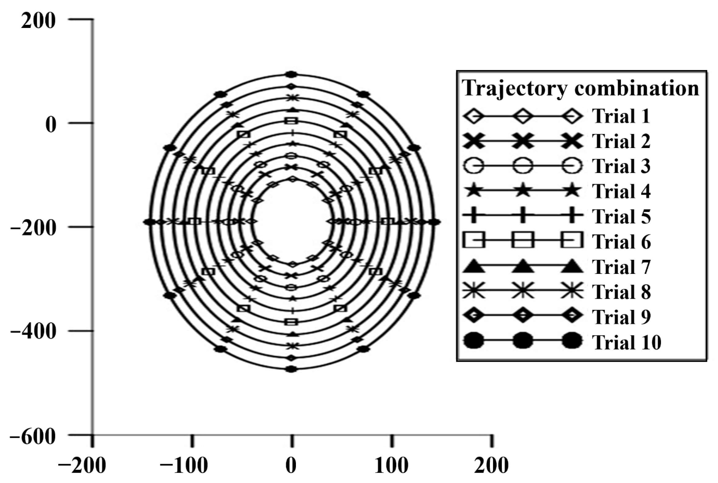
3.1. Working Trajectory of the Dibbling Mechanism

The input and output rpm ratio for each gear train was computed for both the primary and the connecting links by utilizing the combinations shown in Table 2. Therefore, nine combinations were developed—A-D, A-E, A-F, B-D, B-E, B-F, C-D, C-E, and C-F—to achieve the appropriate input and output rpm ratios. However, the C-D combination was considered suitable for further position analysis, since it resulted in a 1:1 ratio for input and output rpm of the primary link and planting hopper, respectively (Table 4).
By considering the input rotational speed of the primary link and the output rotational speed of the planting hopper as identical, the following number of gear teeth combinations were generated, as shown in Table 5. For primary and connecting links, Nd, Ni, Nn and nd, ni, nn represent the number of gear teeth combinations of driver, idler, and driven gear, respectively.
The gear contact ratio plays an essential role in relation to efficient power levels and the smooth meshing of gears. For smooth operation, spur gear meshing requires a gear contact ratio larger than 1.4 and smaller than 2. The findings for 10 trial combinations are illustrated in Figure 6. The results indicate that gear contact ratios of Gd:gi, Gi:gn, gd:gi, and gi:gn meet the requirements for trials 4–10. Therefore, the first three trial combinations were not considered for further analysis. The fourth trial was selected as the most appropriate combination, since the larger gears have greater mass and thus demand more power for their operation.
In order to evaluate the motion trajectory pattern of the rotary planting mechanism, ten trial combinations for the different lengths of the primary and connecting links were obtained. Each trial consisted of three gear trains. As per Equation (15), the lengths of the primary links varied from 48 to 174 mm. Similarly, the connecting link ranged from 40 to 120 mm. These values were further used in Equations (4) and (5) to draw the motion trajectory for each trial. Table 6 shows all the parameters for the rotary planting mechanism for the trial combinations of the primary and connecting lengths.
Figure 7 shows the desired motion trajectory for the rotary planting mechanism. The oval-shaped motion trajectory showed that the connecting link covers twice the distance in a vertical direction compared to a horizontal direction. The results show that the planting hopper travels in a horizontal direction ranging from ±20 to ±120 mm at a ±10 mm interval. However, in a vertical direction, the planting hopper traveled upwards and downwards for each trial in the following ranges: −120 to −270 mm, −100 to −290 mm, −80 to −310 mm, −60 to −330 mm, −40 to −360 mm, −20 to −380 mm, 10 to −400 mm, 40 to −430 mm, 60 to −460 mm, and 90 to −490 mm. The length of the planting hopper was fixed at 190 mm.
The oval or elliptical motion path was derived from the trajectory of different rotational speeds, which were also justified by the simulation results. During the onion planting operation, the trajectory results for 60 rpm were shown to be more stable than the others, with a minimum vibration effect; therefore, 60 rpm appears to be a suitable rotational speed this planting mechanism. A comparison between the simulated and validated experimental results of the motion path trajectory for the gear-driven rotary planting mechanism is shown in Figure 8.

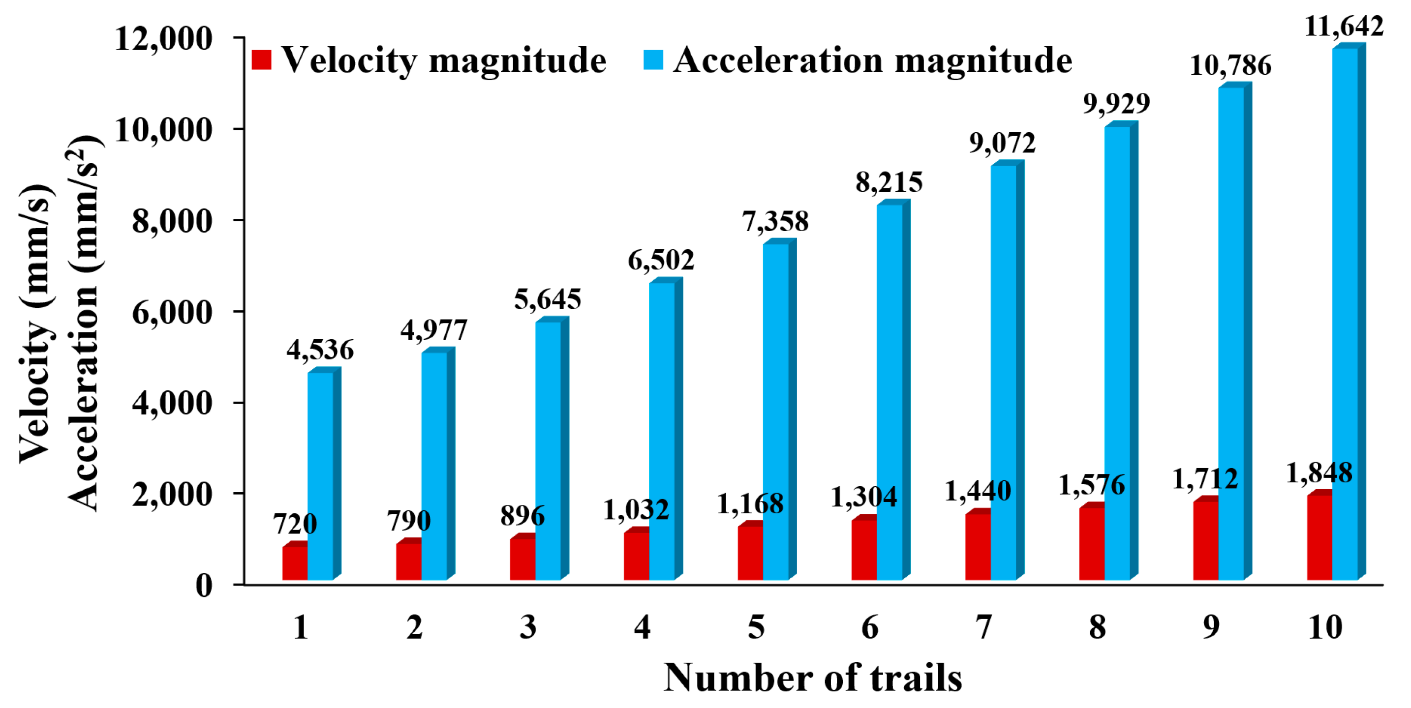
3.2. Velocity and Acceleration Analysis of the Planting Mechanism

When the planting mechanism was operated at a turning speed of 60 rpm, velocity and acceleration steadily increased with the trial number, whereby the length combinations of the primary and connecting links also increase, as illustrated in Figure 9. It was observed that velocity and acceleration were directly proportional to the increase in length in the primary and connecting links of the various combinations. As per Equation (16), the velocity, acceleration, and mass of the planting mechanism were all directly related to power consumption. Within the combinations, the maximum velocity and acceleration ranges were 720–1848 mm/s and 4536–11,642 mm/s2, respectively. The lengths of the primary and connecting link and gear size of the planting mechanism should be decreased while meeting design standards and operating behavior in order to save costs and power consumption.
Simulated magnitude of linear velocities and acceleration of the planting mechanism at 60 rpm are shown in Figure 10. The appropriate length combinations (C-D combination, see details in Table 4) of the primary link, connecting link, and planting hopper were used for the considered simulation trial. Maximum linear velocity and acceleration were observed at 900 mm/s and 5500 mm/s2, respectively. The velocity and acceleration consistently increased with the increase in link lengths for a constant rotational speed.

3.3. Motion Analysis Based on Velocity and Acceleration

The simulated and measured velocities were conducted at 60 rpm of the mechanism, and one complete plating cycle took 1 s. The primary link length (90 mm) and connecting length (70 mm), as per trial 4 (Table 6), were used to validate the velocity of the proposed planting mechanism. Table 7 shows the comparison between simulated and experimental velocity and acceleration of X- and Y-components. The simulated peak velocities for the x- and y-axis were obtained as ±126.64 and ±913.65 mm/s, respectively. During experimental velocity measurements, the peak velocities for the x- and y-axis were found to be +130.34 to −149.25 mm/s and +980.36 to −1184.71 mm/s, respectively. There was no velocity in the z-axis during the simulation.
The operational time for experimental and simulated acceleration measurements was the same as in the velocity analysis. Figure 11 represents the peak simulated and experimental acceleration along the direction of both the x- and y-axis. The maximum simulated accelerations in the direction of the x- and y-axis were found to be ±811.64 and ±5484.67 mm/s2, respectively. The maximum experimental accelerations in the direction of the x- and y-axis were measured as +802.62 to −1026.25 mm/s2 and +7135.27 to −7069.76 mm/s2, respectively.
The experimental results for the peak velocity and acceleration were found higher than the simulated velocity and acceleration. We performed the experimental test in the real time system, which showed minor error due to vibration, speed, and external disturbances, such as operational error. In Figure 8 and Figure 12, it is shown that the working motion path trajectories are not identically elliptical as shown in the simulated results. However, the ranges for the vibration and acceleration satisfied the design of the proposed planting mechanism. Further study is needed to carry out the effect of vibration, speed, and external motions for the planting mechanism.
Several studies reported similar results for motion analysis. Research into the mechanism of a pepper transplanter [23] showed the velocity and acceleration range in the y- and x-axis to be 400 to 1100 mm/s, 500 to 2200 mm/s, 1330 to 23,740 mm/s2, and 2420 to 6140 mm/s2, respectively. A tomato seedling picking device [29] established the maximum velocity and acceleration of its mechanism in the x- and y-axes as 1200 to 2100 m/s and 103,800 and 86,900 mm/s2, respectively. Our study showed an optimum range of velocity and a lower acceleration than previous results. Low velocity would also potentially increase the transferal rate of seedlings [29]. Moreover, the extremely high value of velocity and acceleration may cause damage owing to the rapid movement of energy and force during the operation [30]. The missing and dropped seedlings may appear at peak velocity and acceleration [20]. The velocity and acceleration must be observed while the planting prototype is developed in order to satisfy the design requirements.

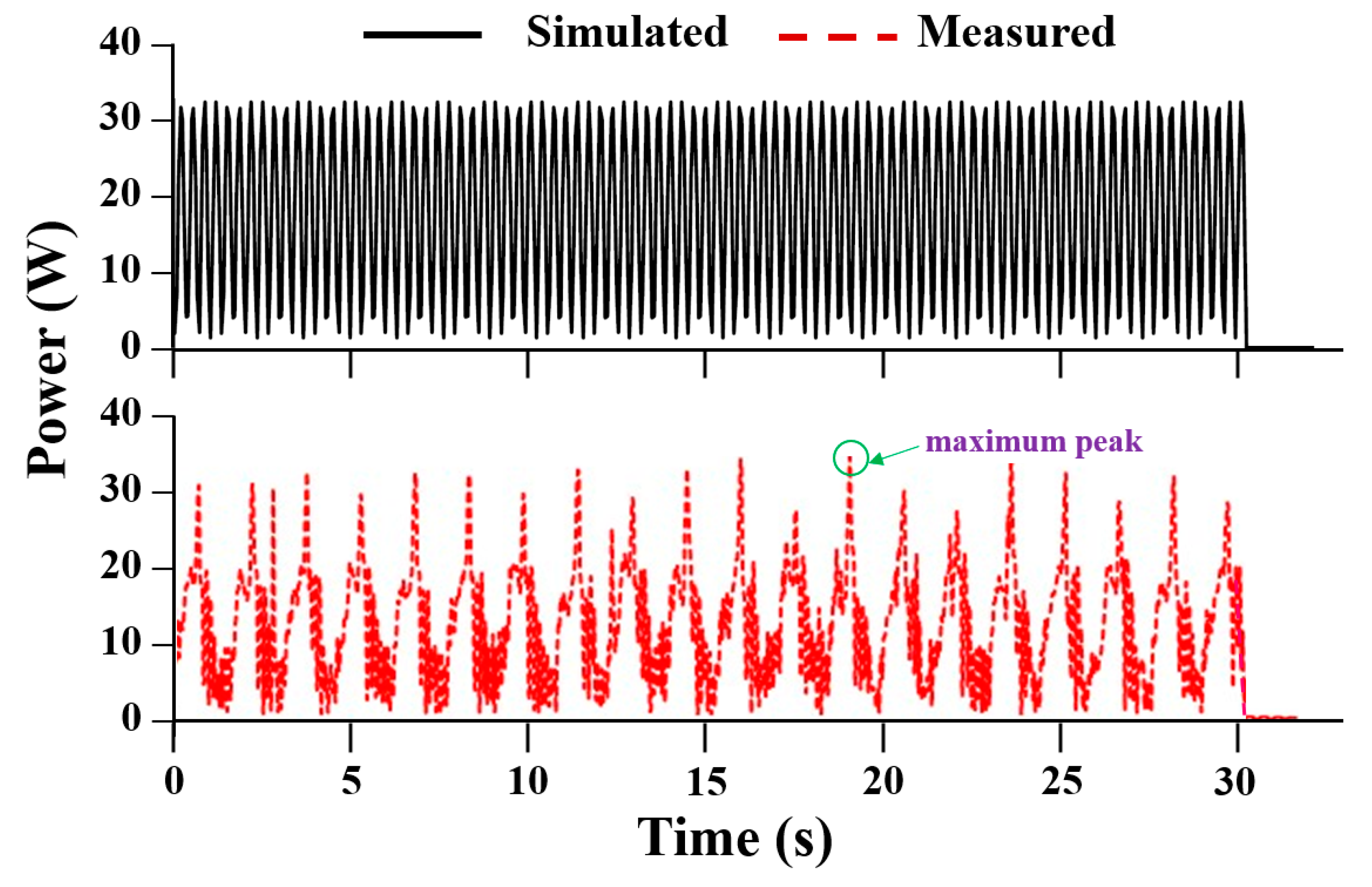
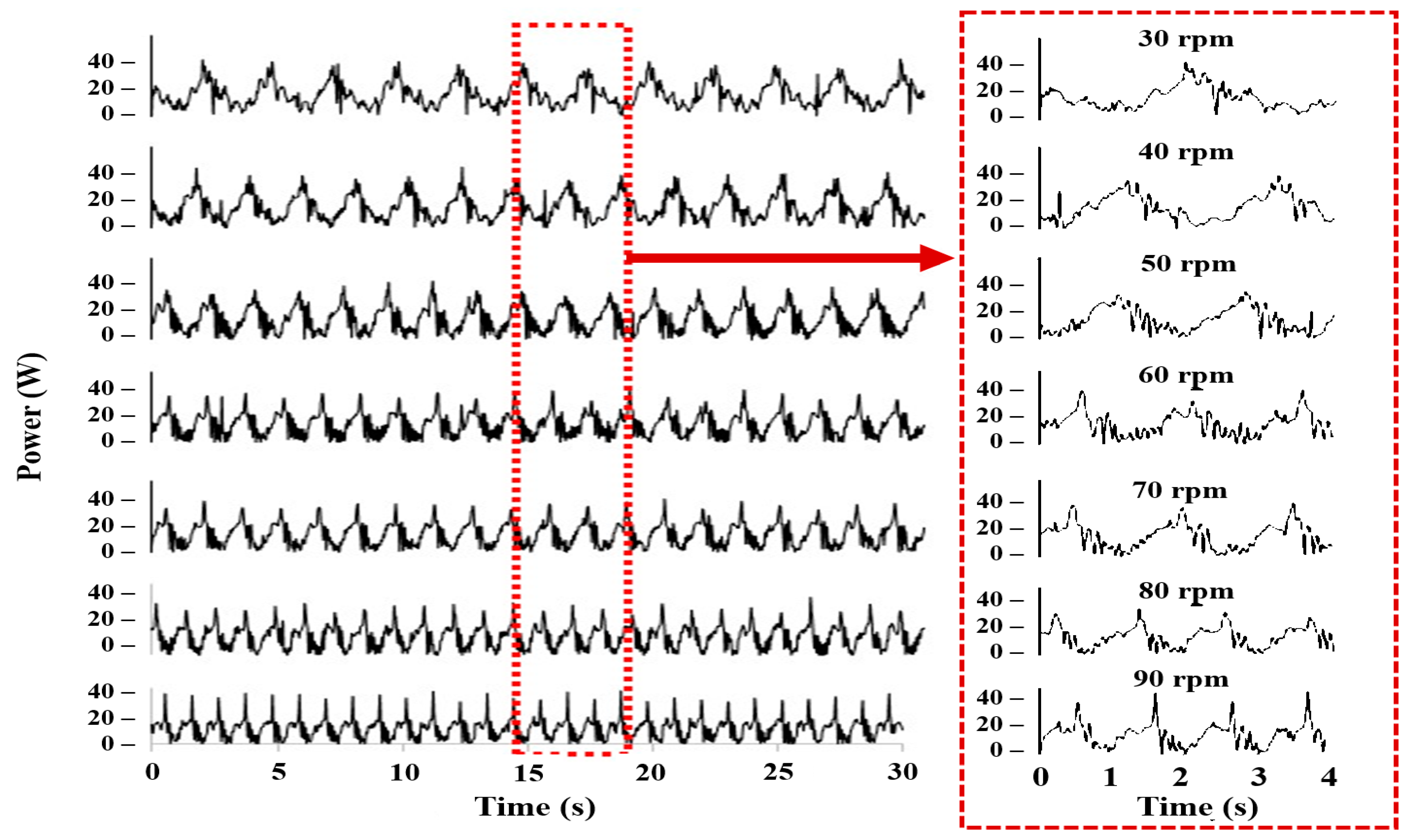
3.4. Power Requirement of the Planting Mechanism

The power consumption was measured for the simulated model and the prototype. The measurements were conducted at 60 rpm to ascertain power consumption. Figure 12 shows the simulated and measured power consumption for the planting mechanism. The required maximum power levels of the planting mechanism for simulated and measured calculations were found to be 33.6 and 35.4 W, respectively, without soil contact. The measured power consumption was 10.54% higher than the simulated value.
The power requirement fluctuated because the planting mechanism was gear-driven, and the gear transmission efficiency varied between 94 and 99.5% [22,31]. Due to the friction losses resulting from the rotating shaft and the undesirable vibration of the test bench, the efficiency of the power transfer was less than the typical efficiency range.
Furthermore, the required power is fluctuating, noisy, and this sudden change (Figure 12) may cause major damage on mechanical parts of the planting mechanism and reduce machine’s life. This is the reason of vibration measurement during the prototype field tests, and also during the design process. In case a machine experiences a significant or sudden shift in vibration, this might indicate that the machine or its components are being subjected to increased forces, loss of rigidity, and gear damage. Certainly, it is needed to reduce the power fluctuation before commercialization and mass production of the planting mechanism.
In addition, the experiment with the prototype was carried out at speeds ranging from 30 to 90 rpm with an interval of 10 rpm in order to ascertain variations in the input-required torque in different conditions. Figure 13 shows the power requirement of the planting mechanism under different speed conditions. The average required torque values of the plating mechanism for 30, 40, 50, 60, 70, 80, and 90 rpm were 0.92, 1.23, 2.54, 5.41, 6.33, 7.23, and 8.16 W. Therefore, the power consumption on the planting mechanism increased when the speed of the machine increased. Table 8 shows the average power consumption for all of the speed conditions. For low speed (30 and 40 rpm), there were no significant differences in power consumption for the planting mechanism. For high speed (40, 50, and 60 rpm) to higher speed (70, 80, and 90 rpm), statistical differences were observed. Power is directly proportional to acceleration, and our data showed that, for a change of 10 rpm, acceleration also changed by an average of 5200 mm/s.

4. Conclusions

In this study, a gear-driven rotary-type planting mechanism was designed for a self-propelled onion transplanter. Kinematic analysis was carried out in order to identify the appropriate link combinations and assess the planting mechanism to optimize the path trajectory, which would improve the working speed and successful transplanting rate. The optimum lengths for the primary, connecting, and planting arms were measured as 90, 70, and 190 mm, respectively, for their use in combination. The optimum diameters of the driver, driven, and idler gears in the primary arm were selected as 56, 48, and 28 mm, respectively. For the secondary connecting link of the planting mechanism, the diameters of the driver, idler, and driven gears were 28, 28, and 56 mm, respectively. The length of the planting hopper was 190 mm, and it remained constant during kinematic analysis. The required maximum power level of the planting mechanism was found to be 35.4 W during the experiment and the single- and double-unit assembly of the rotary planting mechanism can transplant 60 and 120 seedlings per minute, respectively. Comparison of results of the theoretical analysis, simulation, and field tests in our study revealed good concordance. The speed, vibration, and operating condition caused little error in the experimental results. Further analysis would be necessary for the dynamic behavior of the planting mechanism. The outcomes of this study might be helpful in accelerating the adoption of a mechanization process for transplanting onion seedlings.

Author Contributions

Conceptualization, S.-O.C., M.N.R., and M.N.I.; methodology, S.-O.C., M.N.R., and M.N.I.; soft-ware, M.N.I. and M.C.; validation, M.N.I., S.-O.C., and M.C.; formal analysis, M.N.R., M.N.I., and M.C.; investigation, S.-O.C. and S.-J.L.; resources, S.-O.C.; data curation, M.N.I., M.A., S.I., S.K., and I.-S.C.; writing—original draft preparation, M.N.R.; writing—review and editing, S.-O.C., M.N.R., and M.C.; visualization, M.N.R., M.A., S.I., and S.K.; supervision, S.-O.C.; project ad-ministration, S.-O.C.; funding acquisition, S.-O.C. All authors have read and agreed to the published version of the manuscript.

Funding

This work was supported by the Korea Institute of Planning and Evaluation for Technology in Food, Agriculture, and Forestry (IPET) through the Advanced Production Technology Development Program, funded by the Ministry of Agriculture, Food, and Rural Affairs (MAFRA) (Project No. 319043-03), Korea.

Institutional Review Board Statement

Not applicable.

Informed Consent Statement

Not applicable.

Data Availability Statement

Not applicable.

Conflicts of Interest

The authors declare no conflict of interest.

References

  1. Sharma, K.; Mahato, N.; Nile, S.H.; Lee, E.T.; Lee, Y.R. Economical and environmentally-friendly approaches for usage of onion (Allium cepa L.) waste. Food Funct. 2016, 7, 3354–3369. [Google Scholar] [CrossRef] [PubMed]
  2. Sami, R.; Elhakem, A.; Alharbi, M.; Almatrafi, M.; Benajiba, N.; Ahmed Mohamed, T.; Fikry, M.; Helal, M. In-vitro evaluation of the antioxidant and anti-inflammatory activity of volatile compounds and minerals in five different onion varieties. Separations 2021, 8, 57. [Google Scholar] [CrossRef]
  3. Hanci, F. A comprehensive overview of onion production: Worldwide and Turkey. J. Agric. Vet. Sci. 2018, 11, 17–27. [Google Scholar]
  4. KOSTAT. Production Volume of Onions in South Korea from 2009 to 2020. Available online: https://www.statista.com/statistics/958845/south-korea-onion-production/ (accessed on 3 March 2021).
  5. Rasool, K.; Islam, M.N.; Ali, M.; Jang, B.E.; Khan, N.A.; Chowdhury, M.; Chung, S.O.; Kwon, H.J. Onion transplanting mechanisms: A review. Precis. Agric. Sci. Technol. 2020, 2, 196. [Google Scholar]
  6. Feng, Q.; Wang, X.; Jiang, K.; Zhou, J.; Zhang, R.; Ma, W. Design and test of key parts on automatic transplanter for flower seedling. Trans. Chin. Soc. Agric. Eng. 2013, 29, 21–27. [Google Scholar]
  7. Dihingia, P.C.; Prasanna Kumar, G.; Sarma, P.K. Development of a hopper-type planting device for a walk-behind hand-tractor-powered vegetable transplanter. J. Biosyst. Eng. 2016, 41, 21–33. [Google Scholar] [CrossRef] [Green Version]
  8. Khadatkar, A.; Mathur, S.; Gaikwad, B. Automation in transplanting: A smart way of vegetable cultivation. Curr. Sci. 2018, 115, 1884–1892. [Google Scholar] [CrossRef]
  9. Ye, B.; Zeng, G.; Deng, B.; Yang, C.; Liu, J.; Yu, G. Design and tests of a rotary plug seedling pick-up mechanism for vegetable automatic transplanter. Int. J. Agric. Biol. Eng. 2020, 13, 70–78. [Google Scholar] [CrossRef]
  10. Zhao, X.; Ye, J.; Chu, M.; Dai, L.; Chen, J. Automatic scallion seedling feeding mechanism with an asymmetrical high-order transmission gear train. Chin. J. Mech. 2020, 33, 1–14. [Google Scholar]
  11. Hwang, S.J.; Park, J.H.; Lee, J.Y.; Shim, S.B.; Nam, J.S. Optimization of main link lengths of transplanting device of semi-automatic vegetable transplanter. Agronomy 2020, 10, 1938. [Google Scholar] [CrossRef]
  12. Manilla, R.; Shaw, L. A high-speed dibbling transplanter. Trans. ASAE 1987, 30, 904–0908. [Google Scholar] [CrossRef]
  13. Harrison, R.; Harrison, D.; Zuhoski, P.B., Jr. Computer Operated Automatic Seedling Plant Transplanting Machine. United States Patent U.S. 4,947,579A, 14 August 1990. [Google Scholar]
  14. Dong, F.; Geng, D.; Wang, Z. Study on block seedling transplanter with belt feeding mechanism. Trans. Chin. Soc. Agric. Mach. 2000, 31, 42–45. [Google Scholar]
  15. Park, S.H.; Kim, J.Y.; Choi, D.; Kim, C.; Kwak, T.; Cho, S. Development of walking type Chinese cabbage Transplanter. J. Biosyst. Eng. 2005, 30, 81–88. [Google Scholar] [CrossRef]
  16. Kumar, G.P.; Raheman, H. Development of a walk-behind type hand tractor powered vegetable transplanter for paper pot seedlings. Biosyst. Eng. 2011, 110, 189–197. [Google Scholar] [CrossRef]
  17. Han, L.; Mao, H.; Hu, J.; Kumi, F. Development of a riding-type fully automatic transplanter for vegetable plug seedlings. Span. J. Agric. Res. 2019, 17, e0205. [Google Scholar] [CrossRef]
  18. Jo, J.S.; Okyere, F.G.; Jo, J.M.; Kim, H.T. A study on improving the performance of the planting device of a vegetable transplanter. J. Biosyst. Eng. 2018, 43, 202–210. [Google Scholar]
  19. Yang, B.; Zhang, G.; Ran, Y.; Yu, H. Kinematic modeling and machining precision analysis of multi-axis CNC machine tools based on screw theory. Mech. Mach. Theory 2019, 140, 538–552. [Google Scholar] [CrossRef]
  20. Rasool, K.; Ali, M.; Chowdhury, M.; Kwon, H.; Swe, K.M.; Chung, S.O. Theoretical analysis of velocity, acceleration and torque calculation of a five-bar onion transplanting mechanism. In IOP Conference Series: Earth and Environmental Science; IOP Publishing: Bristol, UK, 2021; p. 012019. [Google Scholar]
  21. Sun, L.; Mao, S.; Zhao, Y.; Liu, X.; Zhang, G.; Du, X. Kinematic analysis of rotary transplanting mechanism for wide-narrow row pot seedlings. Trans. ASABE 2016, 59, 475–485. [Google Scholar]
  22. Iqbal, M.Z.; Islam, M.N.; Ali, M.; Kabir, M.S.N.; Park, T.; Kang, T.G.; Park, K.S.; Chung, S.O. Kinematic analysis of a hopper-type dibbling mechanism for a 2.6 kW two-row pepper transplanter. J. Mech. Sci. Technol. 2021, 35, 2605–2614. [Google Scholar] [CrossRef]
  23. Islam, M.N.; Iqbal, M.Z.; Ali, M.; Chowdhury, M.; Kabir, M.S.N.; Park, T.; Kim, Y.J.; Chung, S.O. Kinematic analysis of a clamp-type picking device for an automatic pepper transplanter. Agriculture 2020, 10, 627. [Google Scholar] [CrossRef]
  24. Liu, J.; Cao, W.; Tian, D.; Tang, H.; Zhao, H. Kinematic analysis and experiment of planetary five-bar planting mechanism for zero-speed transplanting on mulch film. Int. J. Agric. Biol. Eng. 2016, 9, 84–91. [Google Scholar]
  25. Wang, J.; Howard, I. Finite element analysis of high contact ratio spur gears in mesh. J. Trib. 2005, 127, 469–483. [Google Scholar] [CrossRef]
  26. Rider, M.J. Design and Analysis of Mechanisms: A Planar Approach; John Wiley & Sons: Hoboken, NJ, USA, 2015. [Google Scholar]
  27. Iqbal, M.Z. Design of a Gear Driven Hopper Type Dibbling Mechanism for a 2.7 kW Two-Row Pepper Transplanter. Master’s Thesis, Chungnam National University, Daejeon, Korea, 2019. [Google Scholar]
  28. Islam, N. Structural Analysis of a Clamp-Type Picking Mechanism for a 2.7 kW Automatic Pepper Transplanter. Master’s Thesis, Chungnam National University, Daejeon, Korea, 2020. [Google Scholar]
  29. Han, L.; Mao, H.; Hu, J.; Tian, K. Development of a doorframe-typed swinging seedling pick-up device for automatic field transplantation. Span. J. Agric. Res. 2015, 13, 13. [Google Scholar] [CrossRef] [Green Version]
  30. Paraforos, D.S.; Griepentrog, H.W.; Vougioukas, S.G. Methodology for designing accelerated structural durability tests on agricultural machinery. Biosyst. Eng. 2016, 149, 24–37. [Google Scholar] [CrossRef]
  31. Kuria, J.; Kihiu, J. Prediction of overall efficiency in multistage gear trains. Int. J. Mech. Mechatron. Eng. 2011, 5, 300–306. [Google Scholar]
Figure 1. Schematic view of the onion transplanting mechanism assembly: (a) conveyor mechanism, (b) picking mechanism, and (c) rotary planting mechanism.
Machines 09 00183 g001
Figure 2. Structure and operational trajectory of the planting mechanism: (a) working trajectory of the mechanism, (b) primary and connecting links, and (c) hopper of the transplanter.
Machines 09 00183 g002
Figure 3. Kinematic model of rotary planting mechanism: (a) structure and working trajectory, and (b,c) kinematic representation of the planting mechanism.
Machines 09 00183 g003
Figure 4. Experimental test bench layout with planting device at RDA, Jeonju, Korea: (a) test bench, (b) planting device, and (c) planting device with its all components.
Machines 09 00183 g004
Figure 5. The planting device used in the experiment with an enlarged view of the sensor setup.
Machines 09 00183 g005
Figure 6. Gear contact ratio of primary and connecting links.
Machines 09 00183 g006
Figure 7. Motion trajectory of rotary planting mechanism in different combinations of primary and connecting links.
Machines 09 00183 g007
Figure 8. Working motion path trajectory of the planting mechanism at 60 rpm: (a) simulated, (b) experimental, and (c) comparison of the simulated and experimental results.
Machines 09 00183 g008
Figure 9. Simulated results for the maximum magnitudes of velocity and acceleration for different trial representing different combinations of the primary and connecting links of the planting mechanism (see details in Table 5).
Machines 09 00183 g009
Figure 10. Velocity (mm/s) and acceleration (mm/s2) of the dibbling hopper for all combinations as a function of time (s).
Machines 09 00183 g010
Figure 11. Simulated and experimental velocity and acceleration curves in the x- and y-axis directions.
Machines 09 00183 g011
Figure 12. Simulated and measured power requirement (W) at 60 rpm as a function of time (s).
Machines 09 00183 g012
Figure 13. Power requirement for the planting mechanism at different rotational speeds.
Machines 09 00183 g013
Table 1. Variable notations, definitions, and measurement units.
NotationDefinitions and Measurement Units
PlPrimary arm length, mm
ClConnecting arm length, mm
HDibbling hopper length, mm
GdDriver gear of the primary arm
GiIdler gear of the primary arm
GnDriven gear of the primary arm
gdDriver gear of the connecting arm
giIdler gear of the connecting arm
gnDriven gear of the connecting arm
T1Number of teeth on driver gear
T2Number of teeth on driven gear
d1Diameter of the driver gear
d2Diameter of the driven gear
CRContact ratio of two meshing gear, numeral
ω1Angular velocity of the primary arm, rad/s
ω2Angular velocity of the connecting arm, rad/s
ω3Angular velocity of the dibbling hopper, rad/s
αPressure angle of the spur gears, degree
pConsumed power by the dibbling mechanism, kW
mTotal mass of the dibbling mechanism, g
amMagnitude of acceleration of the dibbling hopper, mm/s2
vmMagnitude of velocity of the dibbling hopper, mm/s
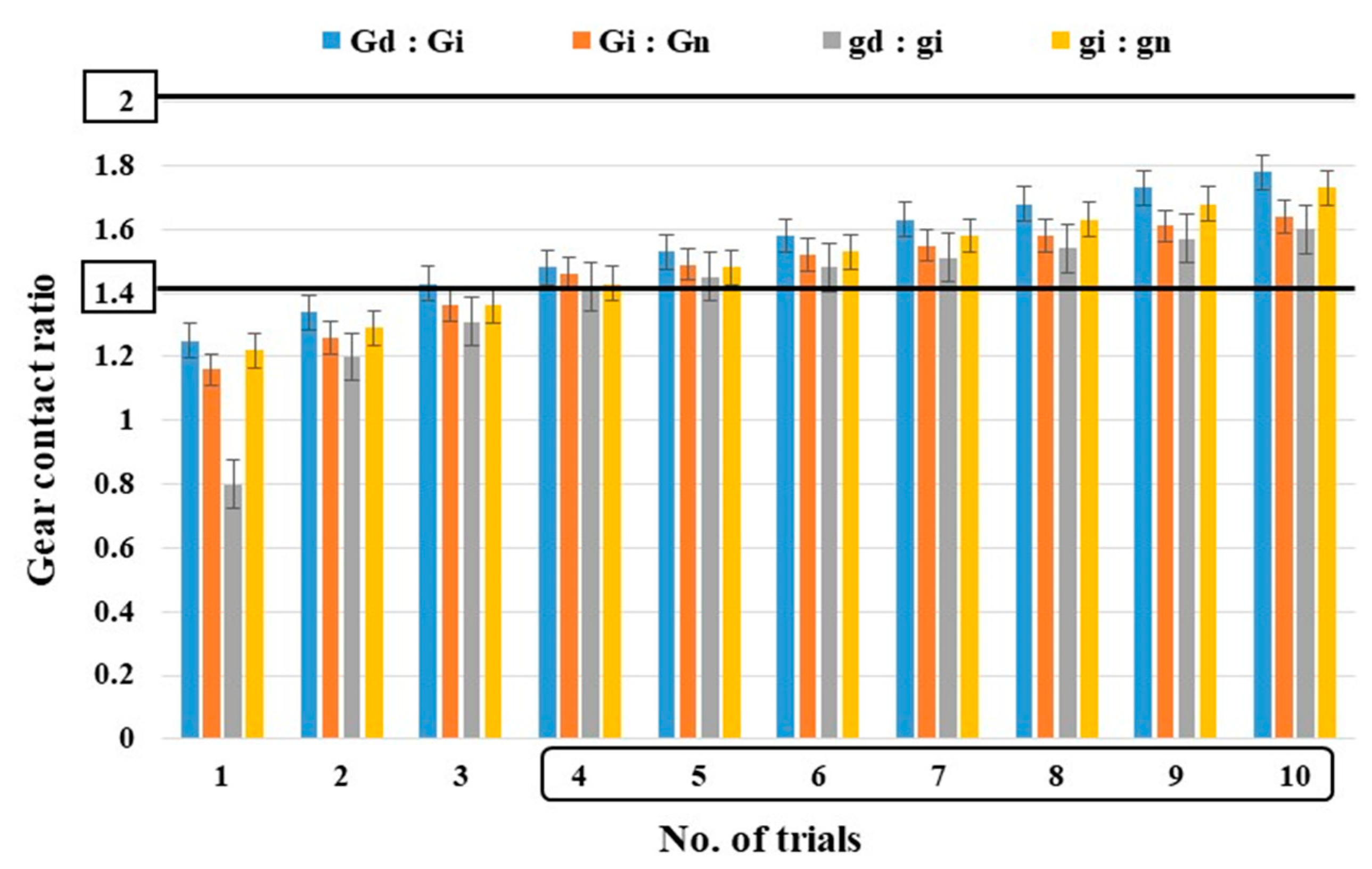
Table 2. Gear train ratio combinations of primary and connecting links.
No. of LinksGearsGear TrainsGear Train RatioGear Ration = Driver: Driven
DriverIdlerDriven
Primary linkGd:Gi:GnA2:1.8:1.41:0.7
B2:1.6:1.21:0.6
C2:1.2:11:0.5
Connecting linkgd:gi:gnD1:1:21:2
E1:1.5:1.81:1.8
F1:2:1.61:1.6
Table 3. Simulation parameters for the planting mechanism.
Fixed ParametersVariables
Forward speedPrimary and secondary links lengths
Planting depthGear diameters
Planting intervalGear ratios
Rotating speed
No. of teeth
Table 4. Input and output rpm ratio for each of the combinations of links as indicated.
Gear TrainsTrial Combinations
A-DA-EA-FB-DB-EB-FC-DC-EC-F
Ratio1.4:11.26:11.12:11.2:11.08:10.96:11:10.9:10.8:1
Table 5. Number of spur gear teeth combinations for primary and connecting links as indicated for the driver, idler, and driven gear for the indicated trial number.
TrialsPrimary Link (Pl)Connecting Link (Cl)
DriverIdlerDrivenDriverIdlerDriven
NdNiNnndninn
1161288816
2201610101020
3242012121224
4282414141428
5322816161632
6363218181836
7403620202040
8444022222244
9484424242448
10524826262652
Table 6. Rotary planting mechanism combinations for primary and connecting link length trials.
TrialPrimary Link Lengths (mm)Connecting Link Lengths (mm)
GdNdGiNiGnNnPlgdndginignnnCl
13216241216848168168321640
24020321620106220102010402050
34824402024127624122412482460
45628482428149028142814562870
564325628321610432163216643280
672366432361811836183618723690
7804072364020132402040208040100
8884480404422146442244228844110
9964888444824160482448249648120
1010452964852261745226522610452130
Table 7. Comparison of simulated and experimental velocity and acceleration for X and Y components.
DirectionVelocityAcceleration
Simulation
(mm/s)
Experiment
(mm/s)
Simulation
(mm/s)
Experiment
(mm/s)
X-component±126.64+130.34 to −149.25±811.64+802.62 to −1026.25
Y-component±913.65±980.36 to −1184.71±5484.67+7135.27 to −7069.76
Table 8. Power requirements (W) at different rotational speeds (rpm) for the planting mechanism.
ParameterPower Requirement (W)
30 rpm40 rpm50 rpm60 rpm70 rpm80 rpm90 rpm
Max.12.320.827.535.444.85265.7
Min.0.010.030.210.230.250.250.29
Avg.0.92 ± 0.431.23 ± 0.682.54 ± 0.885.41 ± 0.746.33 ± 0.327.23 ± 0.918.16 ± 0.19
Publisher’s Note: MDPI stays neutral with regard to jurisdictional claims in published maps and institutional affiliations.

