2.2. Surfaces
The five different artificial turf surface conditions that were used in the investigation were constructed and installed outdoors over an asphalt surface, with the stiffness of the surfaces altered through changes in shock pad material (surfaces 1–3) or changes in carpet and infill material (surfaces 4–5).
All surfaces contained the FieldTurf (FieldTurf, Tarkett Inc., Montreal, QC, Canada) Classic HD 2.5” base carpet with carpet for surfaces #1–4 having a fiber density of 1220 g/m2. Surfaces #1–4 had identical carpet and infill compositions, with the only differences between them being their shock pad material (or lack of shock pad for surface 4). Surface #5 did not contain an underlying shock pad, with changes in stiffness being attained through differences in both the infill composition and density of the carpet fibers (lower density of fibers −1220 g/m2). Surface 4 was termed as Control, due to it being the common surface installed by the manufacturer for high performance sporting activities.
Following construction of all turf surfaces, mechanical drop test measurements were performed following modified American Society for Testing and Materials (ASTM) standards F355 [
15] and F1936 [
16]. Modifications to the testing protocol consisted mainly of a reduction in the number of drops on the smaller sections of artificial turf. Five drops were performed for each surface with the mean values of the peak deceleration quantifying the stiffness of each surface. Through alterations of the shock pad and modifications of the carpet/infill material systematic changes in stiffness were achieved. The specifics of the surface constructions are shown in
Table 1.
2.3. Data Collection
Data collection consisted of two testing sessions; during session one running economy was measured, while during session two sprint, agility and jump performance was measured on the different surfaces.
During the running economy session, athletes were outfitted with a Cosmed K5 breath-by-breath metabolic analysis system (Cosmed, Rome, Italy). As data was collected outdoors, a recent study has shown the Cosmed K5 to be valid for measuring submaximal gas-exchange variables in an outdoor environment [
17]. Immediately before each running economy session, the Cosmed O
2 and CO
2 sensors were calibrated with a gas containing known concentrations of O
2 and CO
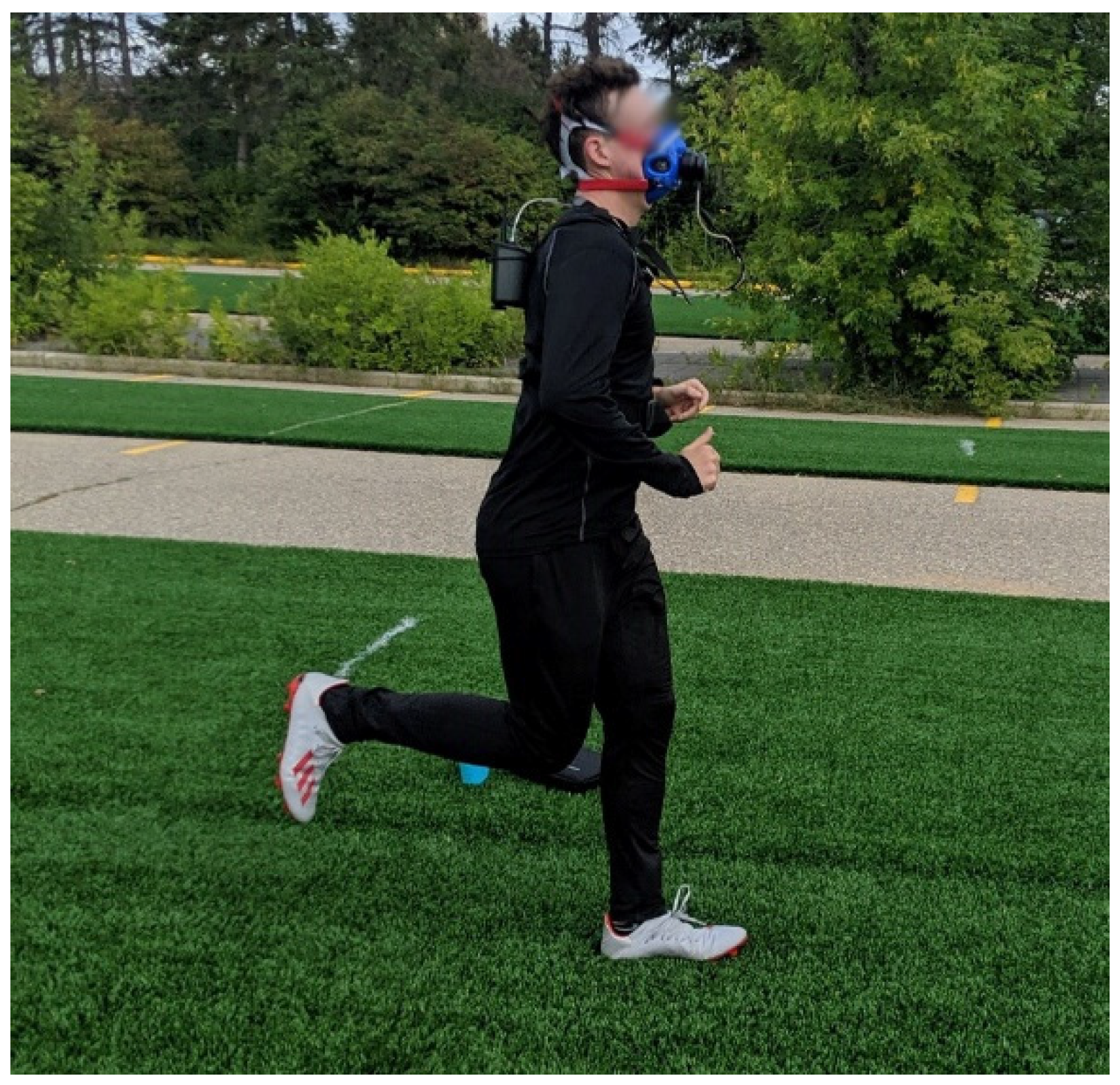
2 following the Matheson Certified Calibration Standard. The final calibration step involved calibrating the sampling turbine with a 3.0 L syringe (Hans Rudolph Inc., Kansas City, MO, USA) to ensure accurate volumetric measurements. When the participant was ready to begin their warmup, they were outfitted with a heart rate monitor and a breathing mask (Hans Rudolph Inc., Kansas City, MO, USA) connected to the Cosmed (
Figure 1). The Cosmed calculated the volumes of O
2 and CO
2 consumed and produced at every breath and averaged these values every 10 s.
The test session began with an incremental running test to a submaximal intensity. The participant began running at 2.5 m/s and increased their speed by 0.22 m/s every 2 min. Running speed was controlled by a computer program that output loud audible beeps set to coincide with when the participant should be reaching the end markers (20 m apart) labelled on each turf surface. The participant continued running at faster speeds until they reached anaerobic threshold (AnT). The identification of AnT uses multiple variables to provide an understanding of exercise intensity but the most commonly used variables during testing were (1) a non-linear increase in pulmonary ventilation and (2) the point of excessive CO
2 production [
18]. Once CO
2 production consistently exceeded O
2 consumption, this indicated that the exercise intensity associated with AnT had been reached. This incremental test served two purposes: (1) it identified the speed at which each participant would run during data collection, which was identified as 1.0 mph below the speed at which AnT was reached and (2) it allowed the participants to warm-up prior to data collection.
After completing this incremental test, the participant was allowed to rest for ten minutes. Then a series of five five-minute constant speed running trials were performed, one on each surface, with five minutes of rest between each trial. The order of surfaces that the trials were performed on was randomized. For each running trial, the average O2 consumption over the last two minutes of the trial was calculated for analysis.
During the second testing session, participants performed three performance drills on each of the different surfaces: 5-10-5 agility drill, 10 m sprint acceleration and running vertical jump.
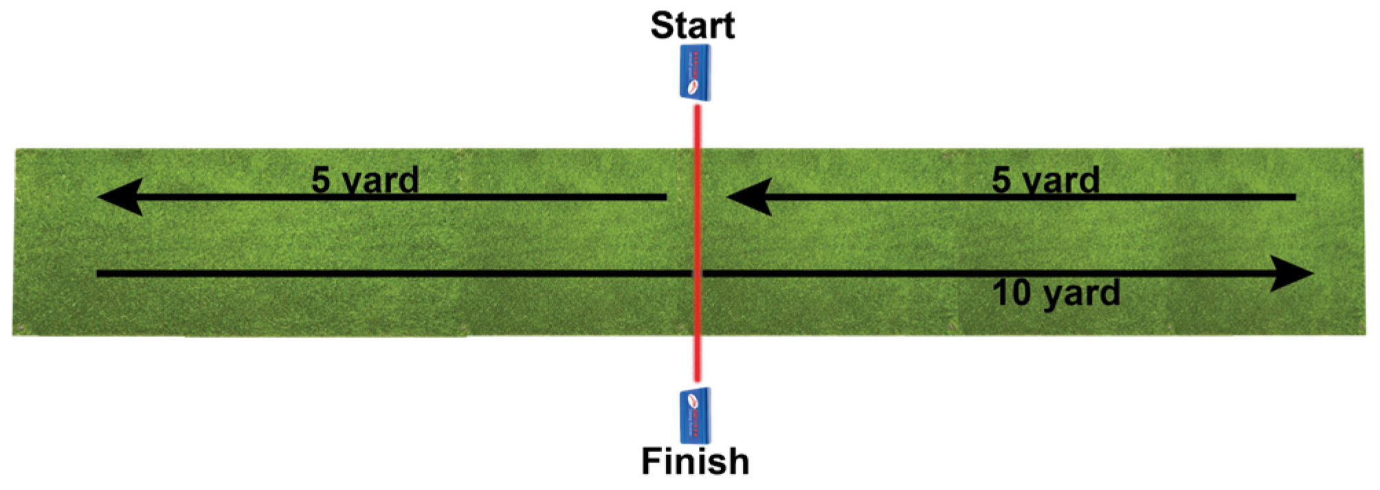
The 5-10-5 agility drill had the athlete starting by straddling a photocell timing light. When instructed to begin, the athletes turned 90° and burst forward 5 yards, then turned 180° and moved in the opposite direction for 10 yards before again turning 180° and reversing direction and sprinting 5 yards back to the starting position (
Figure 2). Brower timing lights were placed in the center of the drill and measured the start and end time. Agility drill performance was defined as the time to complete the drill.
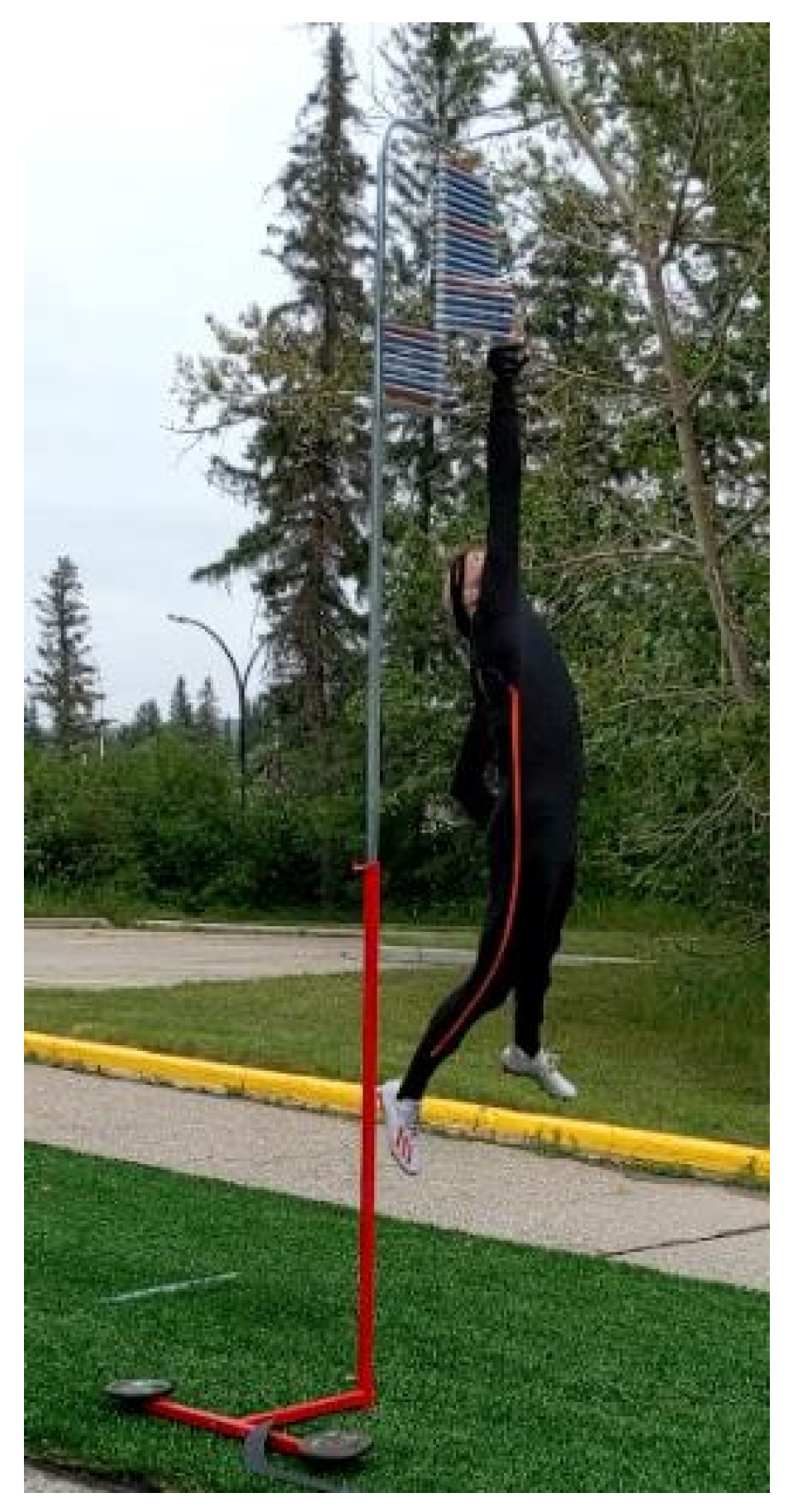
The maximal effort vertical jump was performed with a Vertec jump meter, with the athletes being instructed to jump as high as possible. Participants were allowed to perform any approach they desired with the goal of reaching as high a level as possible on the jump meter. Participants were provided with enough practice trials in order to attain their preferred jumping technique and were required to maintain this technique throughout the duration of the testing session (
Figure 3).
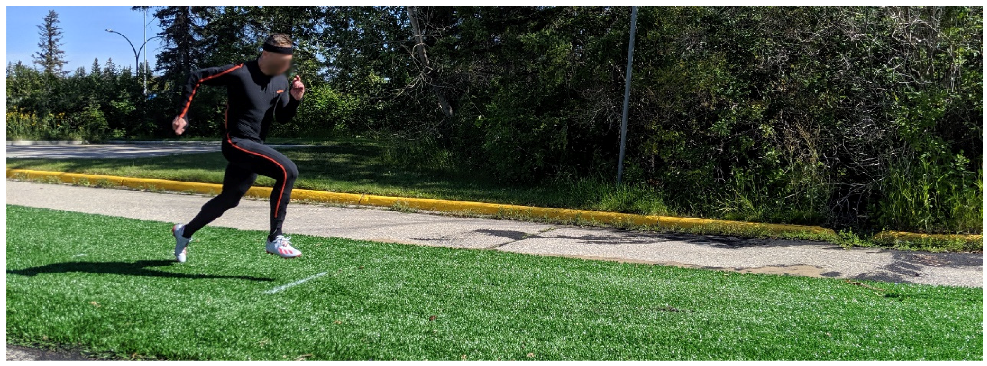
Lastly, participants performed a maximum effort 10 m sprint acceleration. Athletes started in a stationary, self-selected stance at the starting line, accelerated forward while breaking the starting line timing gates and sprinted 10 m through the finish line timing gates (
Figure 4). Sprint acceleration performance was determined as the time to sprint 10 m.
Three trials were collected during each drill on each of the five surfaces, with the athletes also performing practice trials of each movement prior to testing to mitigate learning effects. As with the running session, the surfaces were used in a randomized order and the mean of the three trials on each surface was used for comparisons.
Biomechanical data were also recorded at 240 Hz during the second testing session (sprint/agility/jump) using a full body inertial motion capture system (Xsens, Xsens Technologies BV, Enschede, The Netherlands). The motion capture system consisted of 17 motion trackers placed at anatomical locations on the body with each tracker containing a 3D linear accelerometer, 3D rate gyroscopes, 3D magnetometers and a barometer. Following placement of the trackers, a neutral pose of the athlete was taken that defined the anatomical axis while also determining the relative orientation/location of each tracker. Following completion of the calibration pose, a joint coordinate system was established allowing for 3D kinematics to be measured during each movement. Following data collection, joint angles and foot contact phases were calculated within MVN Analyze 2020.0.2 using proprietary algorithms (Xsens, Xsens Technologies BV, Enschede, The Netherlands) and then output and imported into Matlab R2019a (Mathworks Inc., Natick, MA, USA) where the step of interest was extracted, and peak values were calculated for each trial using custom code. Kinematics during the different movements were only investigated if a performance difference was observed during the sprint, agility or vertical jump test (kinematics were not measured during the running testing session). Due to space constraints, kinematics during a single stance phase for each movement were compared—the closest stance phase at the 5 m mark during the sprint, the initial plant leg during the first change in direction during the agility drill and the initial touchdown leg during the jumping movement of the vertical jump and reach test. Peak sagittal plane angles and angular velocities of the ankle, knee, and hip joint, as well as the trunk and center of mass, were compared to the Control condition.
Prior to the experiment participants filled out an initial questionnaire rating their ideal surface properties of cushioning, on a 5-point Likert scale with text anchors of very soft to very hard. Subjective assessments were then collected using a questionnaire that had athletes rank the surfaces on a five-point Likert scale for the following qualities: cushioning (very soft to very hard), cushioning comfort (very uncomfortable to comfortable), perceived athlete performance (very poorly to very well) and overall surface rating (worst surface ever to best surface ever). These assessments were taken during both testing sessions and were recorded immediately following performance on a specific surface.


