1. Introduction
Recently, gravitational wave (GW) detectors, laser interferometers with kilometer-long arms, have successfully detected gravitational waves. The detectors of the Advanced LIGO and Virgo projects completed their third observing run in 2020. They have detected close to one hundred GW events during the six years since their first detection on 14 September 2015 [
1,
2,
3,
4]. These signals have been used to test the general theory of relativity in the strong-field regime [
5,
6,
7], to understand the physics of the evolution of binary star mergers [
8,
9,
10,
11], to check the validity of the equation of state of neutron stars [
12], to estimate the values of cosmological parameters [
13], and to measure the speed of gravitational wave propagation [
14]. As the sensitivity of the current detectors increases, it is expected that we will soon detect GW signals daily, maybe even several per day [
15]. The scientific information that can be extracted from these signals is directly dependent on accurate calibration of the data that are recorded by the detectors. In order to fully exploit the astrophysical content of the GW detections, continuous calibration with accuracy and precision at or beyond the
level is required [
16]. This requirement includes the amplitude and phase over the entire sensitive frequency band, typically from 10–20 Hz to a few kHz.
Current interferometric GW detectors are variants of Michelson interferometers with optical enhancements that increase their sensitivity to relative arm length variations to the
m level [
17,
18,
19]. The detector arms incorporate optics suspended from multi-stage vibration isolation systems that act as test masses for the passing gravitational waves. A series of optical resonators amplify the phase shift experienced by the circulating laser light. Passing gravitational waves cause differential arm length variations that are encoded in the interferometer output signals that result in laser power fluctuations on the output photodetector of the interferometer. Calibration entails converting these output signals into units of meters of differential arm length variation. These calibrated signals are analyzed to detect gravitational waves and to extract the astrophysical information they carry about the events that generated them. To maintain the optical cavities on resonance, the differential length degree of freedom is controlled using a feedback control servo that suppresses displacements of the test masses via actuators present on parallel cascaded multi-stage pendulums known as reaction chains. Thus, estimating the
external length variations experienced by the interferometer involves characterization of, and correction for the effect of, the feedback control loop [
20]. This is enabled by fiducial periodic displacements of one of the interferometer test masses to measure the response of the interferometer to differential arm length variations. Thus the calibration of the interferometer output signals depends directly on the calibration of these fiducial displacements.
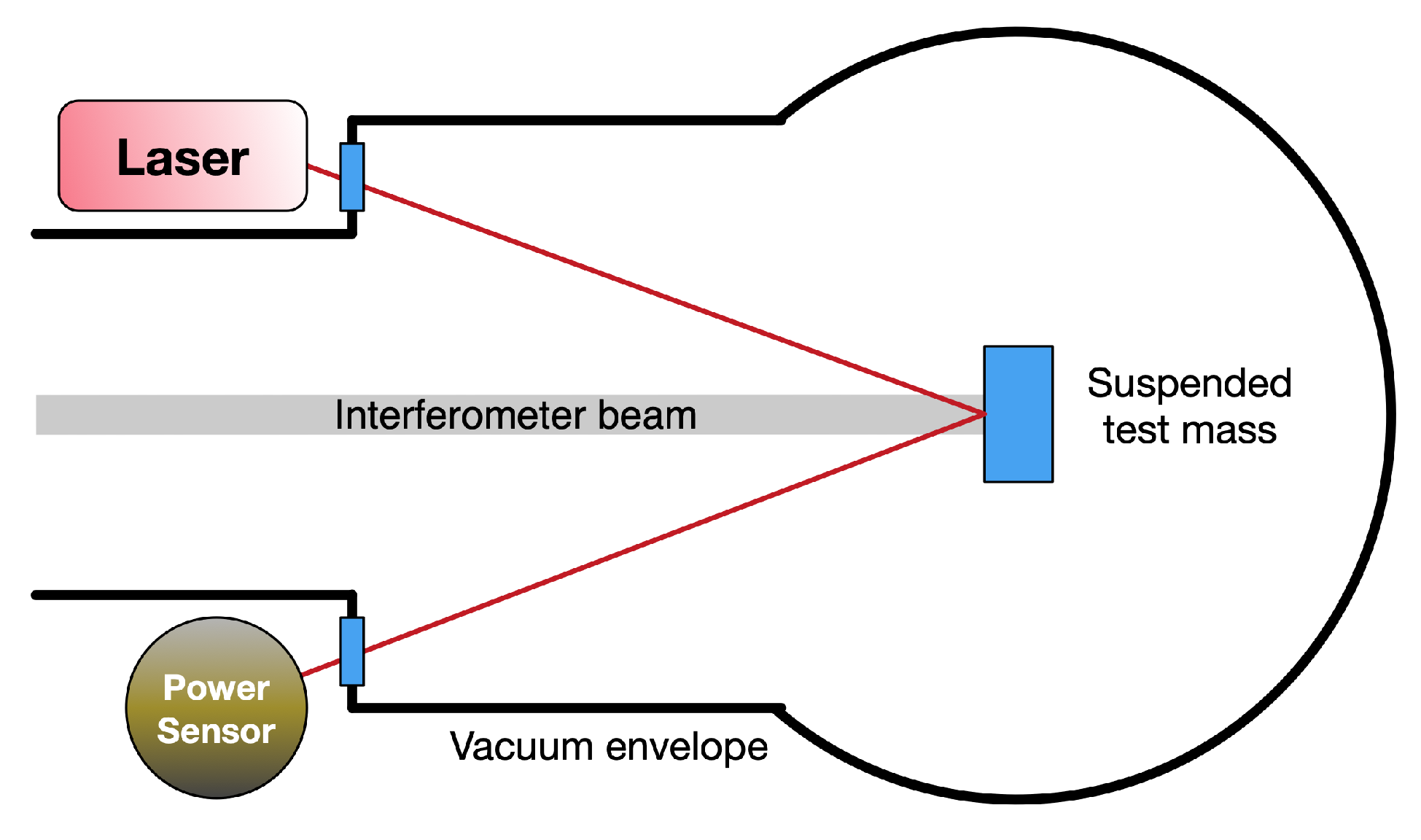
The current generation of GW detectors uses systems referred to as
Photon Calibrators (Pcals), shown schematically in
Figure 1, to generate these calibrated periodic fiducial displacements. These systems employ auxiliary lasers that displace the suspended test masses via laser radiation pressure. The induced displacements are proportional to the amplitude of the modulated laser power and thus the absolute laser power calibration is a crucial aspect of detector calibration. To date, laser power calibration has been achieved using a Pcal laser power transfer standard calibrated by the U. S. National Institute for Standards and Technology (NIST). A series of measurements performed at the LIGO Hanford Observatory (LHO) with this and other transfer standards were used to propagate the NIST calibration to Pcal power sensors operating at the end stations of all interferometers. Using this method, the LIGO Pcal systems achieved
(1-
) uncertainty for the fiducial displacements produced during the most recent observing campaign that ended in April 2020 (see
Section 3) [
21].
The rest of this article provides brief overview of different methods that have been used to generate these fiducial displacements and discusses the working principle of the Pcals as well as their limitations and features. It also elaborates on the method used to achieve fiducial displacements with sub-perecent accuracy using Pcals during the recent LIGO-Virgo observing run. Finally, it discusses the scheme that the network of gravitational-wave detectors plans to employ to achieve sub-percent absolute and relative calibration accuracy for future observing runs using photon calibrators.
2. Evolution of Methods for Generating Calibrated Fiducial Displacements
Over the past two decades, GW interferometers have implemented a variety of techniques to generate calibrated fiducial displacements. During the initial phase of LIGO and even the early period of Advanced Virgo a technique referred to as the
Free-swinging Michelson (FSM) method was used to calibrate the detectors [
22,
23,
24,
25]. This method relies on measurement of Michelson interference fringes and uses the wavelength of the interferometer laser light as a length reference.
Another technique that has been explored in the past is a frequency modulation method [
26]. This technique works by modulating the frequency of the laser light to mimic modulation of the test mass position. Modulating the frequency of the laser light creates effective modulation of the arm length given by the dynamic resonance condition for a Fabry-Perot resonator [
27]. Another modulation, close in frequency to the laser frequency modulation, is injected using the test mass actuator that is to be calibrated. By comparing the signals from the two modulations detected by the single-arm readout sensor, the test mass actuator strength is calibrated [
26].
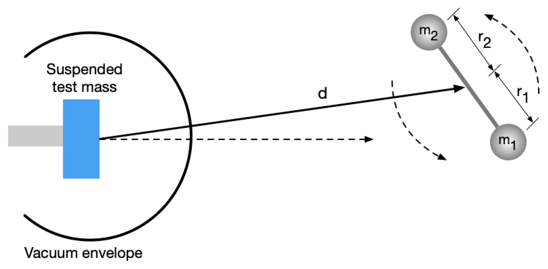
Recently a technique that uses varying gravitational fields to apply forces directly to a detector’s test mass has been explored at various GW interferometers. These systems rely on a combination of rotating masses that produces time-varying forces via periodic changes in the local gravitational field. The force produced by such a system is dependent on the known gravitational constant, the distance between the rotating masses and the detector test mass and the geometrical configuration of the system, shown schematically in
Figure 2.
Such systems have been developed and tested within the Virgo [
28,
29], KAGRA [
30], and LIGO [
31] projects during the last few years and have shown promise for providing absolute fiducial displacment with uncertainty better than
.
The generation of varying gravitational fields using rotating masses has been used in different experimental settings since the 1960s [
32,
33,
34,
35,
36,
37]. However, the usefulness of gravity gradient generators for interferometric GW detectors was first proposed by Matone et al. in 2007 [
38]. Recently, Inoue et al. proposed a scheme that utilizes these gravity field calibrators, called Gcals, or alternatively Newtonian calibrators (Ncals), in conjunction with a photon calibrator to improve the absolute accuracy of the calibration of the GW detector [
30]. However, the first test of a gravity field calibrator in an interferometer setting was carried out at Virgo in 2018 during the second LIGO-Virgo observing run. The Virgo Ncal was an aluminum disk with material removed from two sectors with opening angles of 45 deg. In its first test, the Ncal was spun at 13 Hz and 35 Hz and produced calibrated displacements of the interferometer test mass at twice the rotation frequencies. These calibration lines provided a cross-check of the Free-swinging Michelson method and found agreement within uncertainty limits [
28]. Improved, second generation Ncals were tested in Virgo during the third observing run. These Ncals had the ability to inject calibration lines at frequencies up to 110 Hz. Crosschecks with new Pcal systems installed and used during this run indicated a 3% difference between the two methods. However this difference was within their systematic uncertainty estimates [
29].
LIGO constructed its own Ncal system made up of an aluminium disk with cylindrical cavities in four-fold and six-fold symmetric patterns. These cavities were alternately filled with tungsten cylinders to form quadrupole and hexapole mass distributions. Thus this system can simultaneously produce time varying forces at twice and three times the Ncal rotation frequency. During the third observing run, using the LIGO Hanford detector, it was demonstrated that a calibrated displacement well above the detector sensitivity could be generated using this system with measurement uncertainty at the
level [
31].
With further improvements, Ncals have the potential to reach sub-percent absolute accuracy but have a limited frequency range compared with Pcals. Ncals can play an important role in providing a cross-reference for Pcals, but for the foreseeable future the Pcals will remain the primary calibration method for most GW detectors. This is partly due to their ability to provide fiducial displacements for interferometer calibration across the entire detection band, from 10 Hz to a few kHz.
3. Photon Calibrators: Development and the State of the Art
Photon calibrators were first used on the 10-m prototype detector in Glasgow [
39], and later at the GEO600 detector in Hannover, Germany [
40]. Variations of these instruments have been tested and improved within LIGO over the past 20 years [
21,
41,
42,
43,
44]. During this time, the LIGO Pcals evolved from instruments intended as a sanity check for other calibration methods [
23] to the primary absolute calibration tools for the Advanced LIGO interferometers [
21,
44]. Virgo has developed its own Pcal systems during the last few years and started using them as its primary calibrators during the third observing run [
45,
46]. KAGRA in Japan has also implemented two Pcal systems similar in design to Advanced LIGO but with lasers 10 times more powerful than LIGO’s and the ability to modulate the two Pcal beams independently [
47]. The higher laser power provides the ability to make larger calibrated displacements and independent modulations of two beams could be utilized to minimize unintended rotation induced by the Pcal forces.
Photon calibrators work by applying periodic forces to suspended test masses (optics) via photon radiation pressure using auxiliary power-modulated lasers. These forces are given by
where
is the angle of incidence of the laser beams,
is the amplitude of the laser power modulated with angular frequency
and
c is the speed of light. At frequencies far above the suspension resonance frequencies, the motion of a suspended test mass is well approximated as a free mass. For Advanced LIGO test masses, with suspension resonance frequencies around 1 Hz, the discrepancy between the actual motion and the free-mass approximation is less than 0.1% above 20 Hz [
21]. Thus the periodic longitudinal motion of the test mass is directly proportional to the modulated laser power applied to it, given by [
43]
where
M is the mass of the suspended optic and the negative sign indicates that the test mass motion is 180 deg. out of phase with the applied force.
M and are typically determined with accuracies better than 0.1%. The dominant source of uncertainty is the measured laser power.
The forces applied by photon calibrators can also cause unwanted rotation of the suspended test mass if the forces are not centered on the test mass surface or, in the case of multiple beams, if the powers of the beams are not balanced. If the interferometer beam is not centered on the test mass, this rotation will be sensed by the interferometer as a length change. Including rotation-induced length changes, Equation (
2) can be rewritten as [
43]
where
I is the moment of inertia of the suspended test mass about the center of its front surface and
and
are the displacement vectors of the Pcal center of force and the interferometer beam, respectively, from the center of the test mass surface. Ideally, the detectors are designed to operate with the interferometer beam at the center of test masses, but there can be situations where the interferometer beam is offset from the center of the test mass. During the third observing run, LIGO’s Hanford detector operated with the interferometer beam displaced from the center of the ETM by as much as a few cm to mitigate the impact of point defects in the mirror coatings [
48].
During the first observing run in the advanced LIGO era, cameras were installed as part of the Photon calibrator systems and Pcal beam positions were estimated using the images captured by these cameras. Beam positions were subsequently adjusted using steering mirrors located outside the vacuum envelope [
44]. However, these camera systems were removed later, between the first and second observing runs, to mitigate concerns regarding noise introduced by scattered light reflecting from the camera lens and back into the interferometer beam [
49]. Currently Pcal beam positions in LIGO are adjusted during vacuum incursions to ensure that the net force acts at the center of the test mass. They are subsequently monitored using the position of the the beams as observed at the entrance of the integrating sphere that receives the light reflected from the test mass [
21].
In principle, one could calculate and subtract the contribution from rotation using Equation (
3), but because we do not know the magnitude and direction of any unintended displacements of the Pcal beams, maximum estimated displacements are used and the resulting rotation component is treated as an additional source of uncertainty, added in quadrature with other contributions to determine the total uncertainty [
43,
50].
Earlier LIGO Pcals were designed with a single-beam configuration. In this configuration the force is applied at the center of the optic to minimize unwanted rotation but it elastically deforms the mirror surface at the center of the test mass, the most sensitive region of the interferometer, introducing significant calibration errors if not taken into account. This effect, due to so-called
local elastic deformation, was first investigated by Hild et al. in 2007 [
51]. Goetz et al., in 2009, demonstrated that the errors in calibration due to this effect could be as large as
at a few kHz [
43] when assuming that the test mass motion is described by free-mass motion. Subsequent LIGO Pcal systems moved to two beam configurations with beams displaced from, and diametrically opposed about, the center of the face of the test mass. This ensured that the local elastic deformations due to the Pcal beams were far away from the region sensed by the interferometer, the center of the test mass [
43].
Advanced Virgo Pcals use a single-beam configuration and model their test mass displacement using a combination of free-mass motion and contributions from the excited solid-body modes of the optic, primarily the
drumhead mode measured at 7813 Hz [
45,
46]. In this configuration the motion sensed by the interferometer goes to zero at the crossover frequency (∼2 kHz) because the free-mass motion is 180 deg. out of phase with, and equal in amplitude to, the elastic deformation as shown in Figure 5 in [
45]. However, the sensed displacements at frequencies above the crossover are larger than the free-mass motion and they increase dramatically as the excitation frequency approaches that of the drumhead solid-body mode. In principle, if modeled and compensated correctly, this enables probing the interferometer calibration more efficiently at higher frequencies. Advanced LIGO Pcals, designed with two beams that are placed near the nodal circle of the drumhead mode, minimize the contribution from elastic deformation. They thus provide displacement that is closer to the motion of a free mass, but large displacements at high frequencies require significantly more laser power or longer integration times. One can imagine using both configurations in a single Pcal system: using the two beam configuration to calibrate the detector at frequencies where the free-mass motion dominates, then moving both beams to the test mass center to probe the calibration at higher frequencies using the apparent motion due to elastic deformation.
In order to enable calibration of the interferometer with accuracy approaching
, the signal-to-noise ratio (SNR) of the Pcal fiducial displacements (calibration lines), some of which are in the interferometer’s most sensitive band, must be greater than 100. Because the modulated Pcal forces that generate these lines are applied continuously, directly to the ETM surface, ensuring that displacement noise is not introduced at other frequencies is critical. This could result from either unwanted harmonics of the calibration line modulations or the inherent relative power noise of the laser source. Feedback control systems referred to as
Optical Follower servos are commonly employed to address both of these potential sources of unwanted displacement noise. LIGO uses analog servos with unity gain frequency near 100 kHz [
52]; Virgo uses digital servos. The servos enable deeper power modulation with minimized distortion by compensating for nonlinearities in the acousto-optic modulator drive circuits. This increases the useful range of motion that can be achieved with the available Pcal laser power [
44].
4. Laser Power Calibration for Photon Calibrators
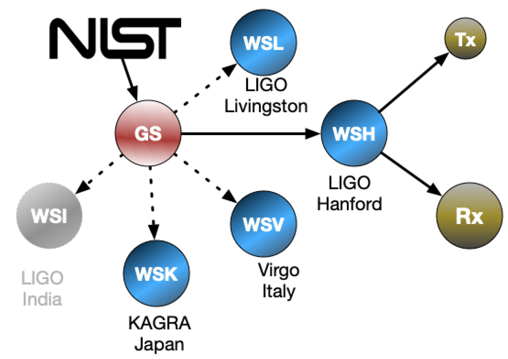
Measuring the modulated laser power reflecting from the mirror with the required accuracy is one of the primary challenges for Pcal systems. During the last three observing runs, laser power calibration traceable to SI units has been provided by the US National Institute for Standards and Technology in Boulder, Colorado (NIST) and those calibration were transferred to the Pcal power sensors at the two LIGO observatories as shown schematically in
Figure 3.
Virgo and KAGRA participated in this scheme during the third observing run that finished in March 2020 and the LIGO India detector was expected to participate once it became operational. In this scheme, the calibration transfer is performed using integrating sphere based power sensors in which a photodetector assembly is mounted on an exit port of the sphere. The inner surface of the integrating sphere is lined with a diffuse scattering material that scatters the light that enters the sphere via multiple reflections, creating a uniform distribution of laser light inside the sphere. One such power sensor, referred to as the Gold Standard, was maintained in one of the optics laboratories at the LIGO Hanford Observatory (LHO). It was calibrated annually at NIST, providing laser power calibration traceable to SI units. During the first and second observing runs the 1-
uncertainty of the NIST calibrations was
. The uncertainty of the NIST calibration of the Gold Standard performed at the start of the O3 observing run was
[
53].
The calibration obtained from NIST via the Gold Standard was transferred to similar power sensors called Working Standards. This calibration transfer was realized through a series of responsivity ratio measurements in which two power sensors are placed in a beamsplitter’s reflected and transmitted laser beam paths and the time series of the detector outputs are recorded. A second set of time series are recorded with the position of the spheres swapped. The square root of the product of the ratios of these four time series provides the ratio of the responsivities of the two power sensors [
44]. The calibration is then transferred to the Pcal power sensors at the interferometer end stations using similar techniques. This process through which the calibration is transferred from a NIST calibrated power sensor to the end station Pcal power sensors, in terms of power reflected from the ETM, has improved significantly within LIGO during the past 15 years and has enabled the calibration of the Pcal power sensors with only a slight increase (less than
) above the Gold Standard calibration uncertainty [
21,
44].
Between 2005 and 2007, national metrology institutes (NMIs) from nine countries performed a key comparison for radiant laser power [
54]. They measured the responsivity of two thermal laser power sensors at three different laser wavelengths and at three different power levels. Relevant for Pcals are measurements made at 1064 nm, close to the Pcal laser wavelength of 1047 nm, and at power levels of 1 W. Though the comparison results were generally in agreement within the stated uncertainties, in a few cases there were differences between the reported values and and the consensus value that were as large as two percent and exceeded the quoted uncertainties. This triggered some concern regarding the achievable accuracy of laser power calibration within the GW community [
55]. This concern and realization of the importance of absolute laser power calibration to the GW community stimulated organization of the
GW Metrology Workshop that was held at NIST in Boulder, Colorado in the USA in March 2019 [
56]. Pursuant to discussions during the workshop, NIST, in collaboration with their German counterpart, the Physiklaisch-Technische Bundesanstalt (PTB) in Braunschweig, Germany, initiated a new bilateral comparison to calibrate an integrating sphere based power sensor of the design currently used by the GW community at 100 mW and 300 mW power levels at the 1047 nm Pcal laser wavelength [
57]. The resulting combined degree of equivalence between the NIST and PTB calibration results of
was well within the 1-
uncertainties of the Gold Standard calibrations provided by NIST [
57]. The report of the comparison concluded that NIST and PTB measurements were sufficiently consistent to support the stated LIGO Pcal displacement uncertainty of
(1-
) during the O3 observing run [
21,
57].
Virgo relied on the Free-swinging Michelson technique to calibrate their detector during the first and second observing runs of the advanced detector era [
25], but started using Pcals as their primary calibration tool for the third observing run that began in April 2019. Calibration of Virgo’s Pcal systems using a Working Standard (WSV) calibrated at LHO revealed that the Virgo Pcal had a calibration error of
[
46]. The calibration of the Virgo data was corrected to account for this error, thus reducing the relative calibration errors between the LIGO and Virgo detectors. The data from all three detectors were used by the analysis pipelines to detect GW signals and infer source parameters. Virgo was able to propagate the NIST calibration, via the Gold Standard and Virgo Working standard, to their end station Pcal power sensors with overall 1-
uncertainty of
[
46]. Most of this increase in uncertainty was attributed to uncertainty in the division of optical losses between the test mass incident and reflected paths due to inability to make in-chamber measurements of optical losses. The relative uncertainties in the estimates of the laser power reflecting from the end test masses and in the Pcal-induced displacement fiducials for both LIGO and Virgo during the third observing run, are shown in
Table 1.
Similarly, KAGRA’s Working Standard (WSK) was calibrated at LHO, using the NIST-calibrated Gold Standard, which was then used to calibrate the KAGRA detector for their first observation run that was held jointly with the GEO600 detector for two weeks in April of 2020 [
47].
This process by which Pcals in the network of GW detectors are calibrated using a single NIST-calibrated standard ensures that the relative calibration errors between the detectors are minimized. However, any systematic error in the NIST calibration will manifest as an error in absolute displacement calibration for all observatories and thus in the absolute amplitude of the signals detected. Thus, the accuracy of the NIST calibration directly impacts our ability to determine the amplitude of GW signals.
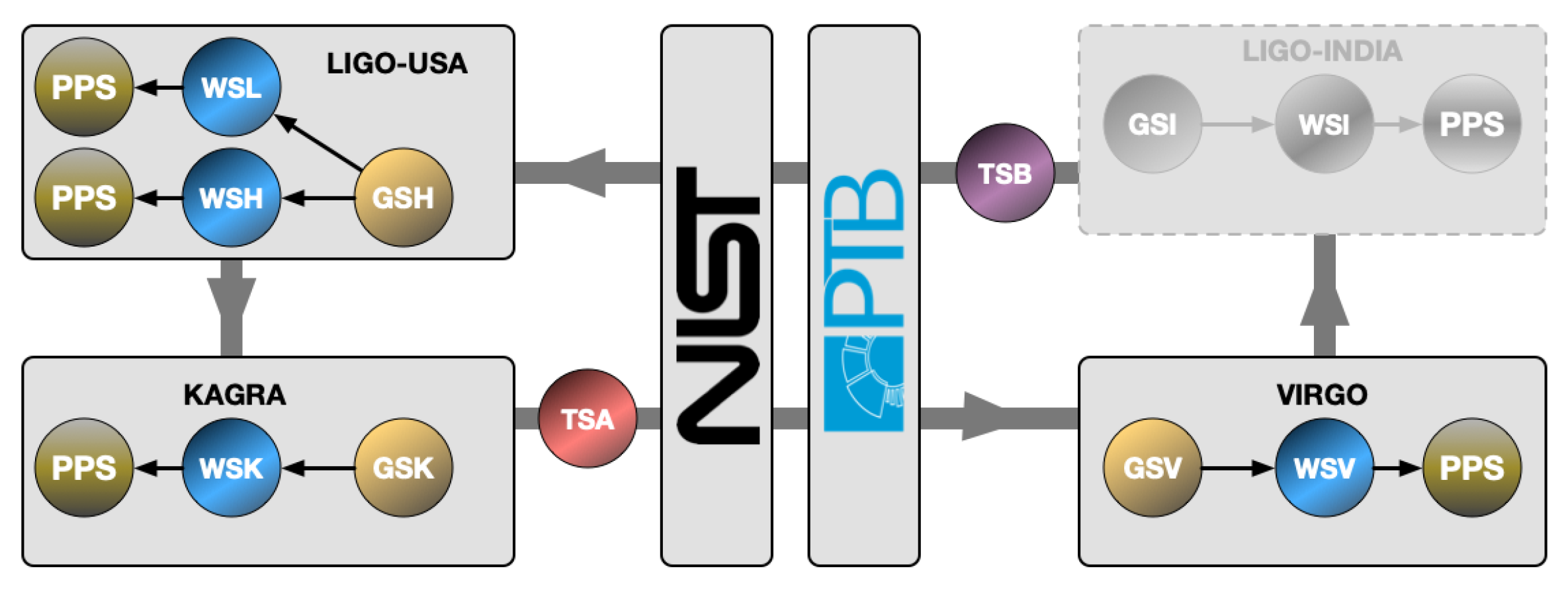
5. Network Calibration for the O4 Observing Run and Beyond
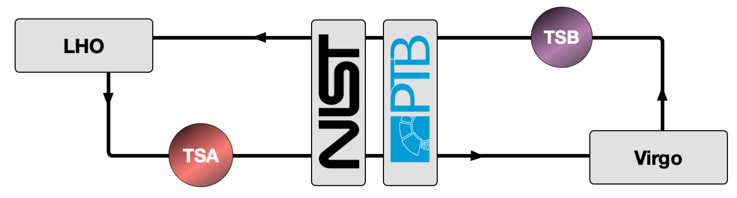
The scheme described above and used to transfer laser power calibration from NIST to the Pcal power sensors at different observatories relied on a single Gold Standard that was calibrated at NIST and maintained at LHO. This burdened a single observatory with calibration of the working standards for all observatories in the network and necessitated leaving the observatories without calibrated working standards for significant periods while they were in transit and undergoing responsivity ratio measurements at LHO. In consultation with collaborators at NIST and PTB a plan was devised to use two transfer standards to deliver laser power calibration to each observatory in the global network. The observatories then use
local Gold Standards and Working Standards to propagate the NMI calibrations to the Pcal power sensors at the end stations as shown schematically in
Figure 4, using methods that have been developed and improved by LIGO over the past decade (see
Section 4).
These new transfer standards, labeled TSA and TSB in
Figure 4, are updated versions of the previous Gold Standard sensor that incorporate spacers with apertures located between the sphere and the photodetector assembly to minimize temperature dependence of the sensor responsivity [
58]. An integrated temperature sensor has also been added for continuous temperature monitoring. The two transfer standards circulate around the loop shown in
Figure 4, once per year with a temporal separation of six months. Thus each observatory receives one of the calibrated transfer standard approximately every six months and each transfer standard is calibrated by both NIST and PTB (consecutively) twice per year. Monitoring of the NMI calibrations of the transfer standards together with the derived calibrations of the Gold Standards at each observatory is expected to reveal any changes that may have occurred during shipping. We expect that experience with executing this scheme will reveal potential deficiencies and lead to improvements in the power sensors, the shipping methods, and the loop circulation strategy, if required.
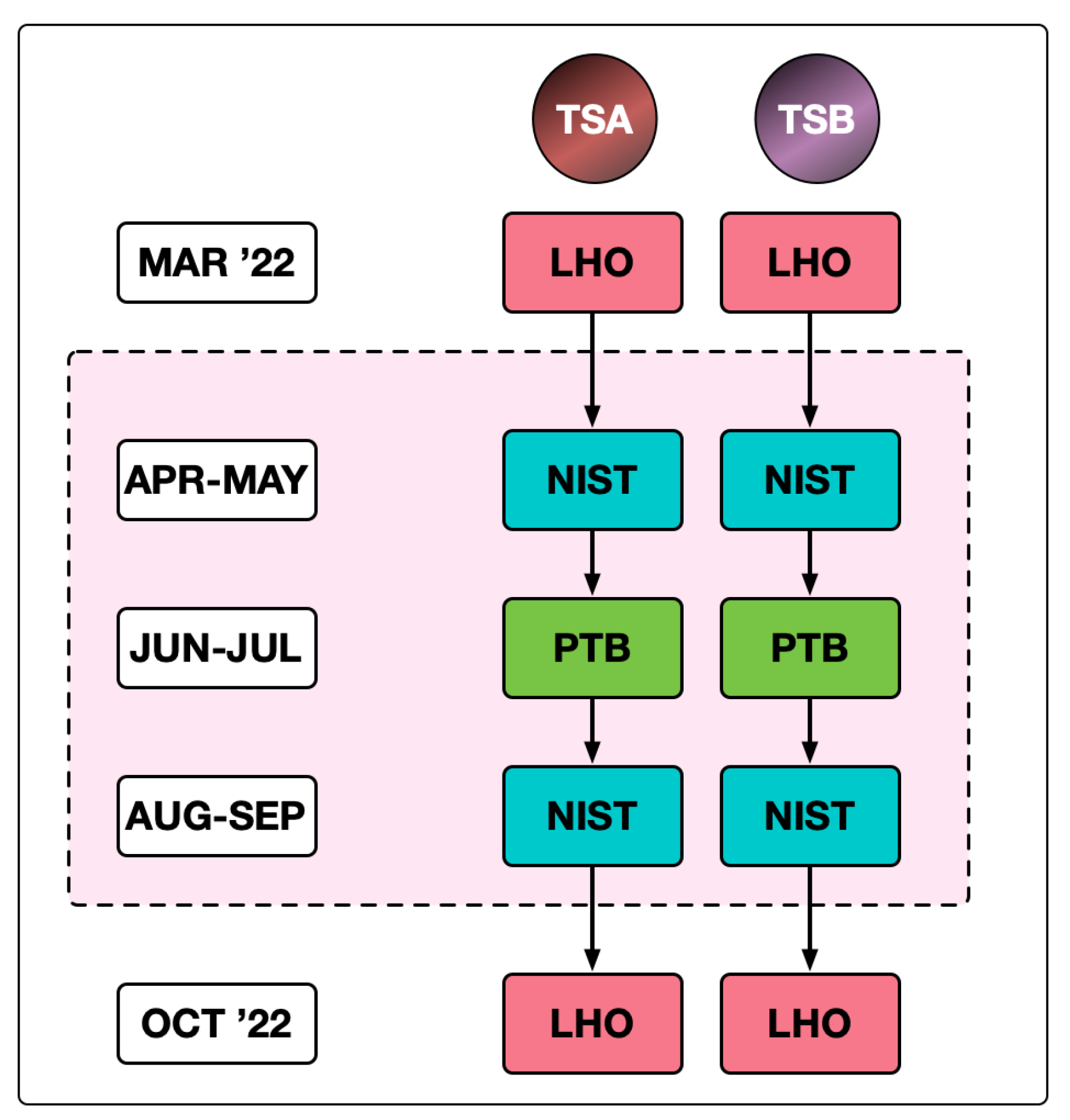
In preparation for implementing this new calibration scheme for the O4 observing run that is scheduled to begin in December 2022, a NIST:PTB bilateral comparison of the transfer standards is planned. The schedule for the comparison is shown in
Figure 5.
This comparison will be similar to the recent bilateral comparison reported in [
57] except that the updated power sensors will be used and NIST will employ the recently implemented
PARRoT [
59] primary standard. The combined uncertainty in the degree of equivalence for the previous bilateral comparison (see
Section 4) was
(1-
), dominated by the stated uncertainty in NIST’s calibration (
) [
57]. The uncertainties in NIST calibrations using the new PARRoT standards are expected to be approximately
, similar to the uncertainty of the PTB calibrations. This is expected to significantly reduce the uncertainty in the bilateral degree of equivalence for this new comparison and better enable identification of changes in the transfer standards that might occur during shipping. Eventually, this should lead to reductions in the overall uncertainty in the calibration of the Pcal-induced displacements.
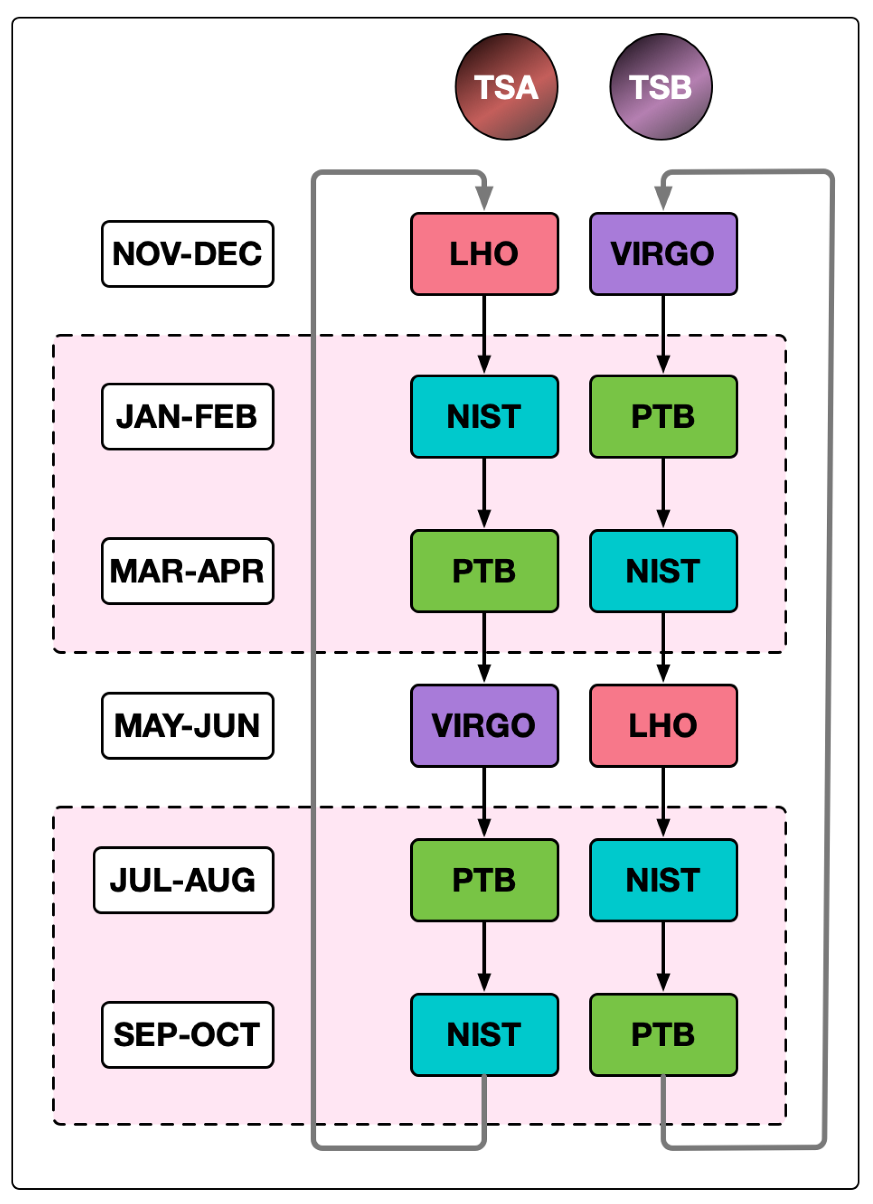
When the bilateral comparison is complete, the two calibrated transfer standards will be shipped back to LHO and the modified version of the network calibration scheme shown in
Figure 6 will commence.
The initial scheme involves only the LIGO and Virgo detectors, but we expect that KAGRA will join the calibration scheme during the O4 observing run. Calibrating the KAGRA Working Standard using the LIGO Gold Standard, as carried out during the O3 observing run, will provide calibration traceable to SI units for KAGRA in the meantime. The schedule for the modified calibration scheme is shown in
Figure 7. Substantial reductions in the intervals allotted for each measurement may be realized as we gain experience with this plan. In this preliminary scheme, each transfer standard is calibrated by NIST and PTB sequentially, both before and after visiting each observatory. This is intended to rapidly provide data relevant to the stability of the transfer standards, the shipping processes, and the calibration procedures at both the observatories and the NMIs. After gaining experience with this calibration strategy during the first year, we expect to carry out an optimized version of this scheme annually, eventually including the LIGO Aundha Observatory in Maharashtra, India. Based on experience to date propagating the NIST calibrations to the Pcal sensors at the LIGO detector end stations, and assuming that the other observatories will be able to transfer the calibrations with similarly small increases in uncertainty, this scheme should provide relative and absolute calibration of the Pcal-induced displacement fiducials at well below the
level for the O4 observing run and beyond.
6. Looking Ahead
Photon calibrators, now the primary calibration tool for all detectors in the global network, have improved significantly over the past fifteen years. These systems provide the calibrated displacement fiducials that determine the overall absolute calibration of the detector output signals. In doing so, they rely on sub-percent accuracy in the calibration of their laser power sensors. Ensuring that the relative calibration errors between all detectors in the network are below the one percent level is enabled by referencing to a common set of measurements or standards, as in the calibration scheme planned for the O4 observing run.
Implementation of Newtonian calibrators is also evolving rapidly, especially at the Virgo observatory. It is possible that they will soon provide continuous, accurate calibration fiducials at the observatories where they are implemented—an important analog to the fiducials generated by the Pcal systems. These Ncal fiducials could obviate the need for in-chamber measurements of the optical efficiencies of the paths between the Pcal transmitter module and the test mass and between the test mass and the receiver module that are required to achieve sub-percent accuracy with the Pcal systems. They could also inform the impact of unintended rotations of the test mass induced by Pcal forces.
Eventually, as the signal-to-noise ratios and frequency of GW detections increase, the GW signals themselves may provide a sufficiently accurate
astrophysical calibration for comparison with the existing calibration methods. Because waveforms of coalescing compact binary systems are predicted by the Einstein’s theory of general relativity, the observed signal amplitudes and phases can be compared with those of the predicted signals to constrain the frequency dependence of the detector responses and the relative calibration between detectors in the network [
60,
61]. Additionally, if the GW signal has an electromagnetic counterpart, the luminosity distance to the source can be determined using the redshift of the electromagnetic signal, within the limits of the accuracy of the Hubble constant. This estimate of the luminosity distance together with the predicted waveform amplitude provided by general relativity enables absolute amplitude calibration of the detectors via the GW signals detected [
60,
62]. However,
overall amplitude calibration using this method with expected signal SNR levels would require hundreds of GW detections with optical counterparts. Achieving
relative calibration accuracy between detectors in the network using GW signals without optical counterparts would require detecting thousands of signals [
60]. Another astrophysical calibration method that has the potential to provide percent-level relative calibration of detectors in the network is a
null stream technique that uses data streams that contain calibration errors as residuals. However this method would still require an independent hardware-based method to determine the absolute scale of the calibration [
63].
Calibrating a GW interferometer that operates with numerous resonating optical cavities with suspended mirrors over the entire sensitive frequency band and over year-long periods is a complicated and challenging task. Doing so with sub-percent accuracy has yet to be achieved. But there has been significant progress over the past few years and this goal now seems to be within reach [
20,
64]. It requires calibrated displacement fiducials with sub-percent accuracy. Experience with the LIGO Pcal systems during the O3 observing run [
21], the results of the recent NIST:PTB bilateral comparison using a Pcal power standard [
57], and the proposed scheme for absolute and relative calibration of the global network of GW detectors discussed above, indicate that calibration accuracy will not limit the ability of the network to extract astrophysical information from the signals they detect during the upcoming O4 observing run and well into the future.


