Abstract
The sintering temperature and holding time have a significant impact on the densification of a ceramic compact. In this study, alumina inserts were made with varying sintering temperatures and holding times. The procedure began with the compacting of alumina powders inside a mould with trapezium and round shapes. These inserts were then sintered between 1200 °C and 1400 °C for 5 to 9 h holding time. The sintered samples underwent analysis based on the shrinkage size, density, and microstructure. The sample with the highest density was chosen for additional machining tests. The results showed that the alumina shrinkage ranged from 3 to 6%, with a maximum relative density of 91.3% recorded when the sintering parameter was applied at 1400 °C and a 9 h holding time. The transition of the grain growth was observed depending on the sintering temperature and heating duration. When machined with AISI 1045 carbon steel, the sintered alumina inserts achieved a maximum tool life of 35 s at a cutting speed of 350 m/min. The sintered inserts exhibited brittle characteristics with a dominant notch wear and abrasive mechanisms.
1. Introduction
Machining operations are among the most important manufacturing processes in metal-based production industries. Technically, this process involves the action of material removal from the workpiece by the cutting tool to achieve the required shape and dimension. The cutting tool is the most important criterion for achieving efficient machining processes. Cutting tool materials for common workpiece materials include high-speed steels, ceramics, carbide, and cutting tools with coating capabilities. Each cutting tool has its own set of capabilities, and its application is dependent on the workpiece’s flow stress and processing parameters. Other important criteria for the use of these cutting tools are the cost and the designation of their intended function [1,2,3].
The majority of industries use high-speed steel (HSS) and carbide cutting tools as their primary materials in machining operations. This is due to the fact that HSS and carbide have the sufficient hardness to perform metal shearing. Furthermore, HSS and carbide are widely available at reasonable costs. However, the use of HSS and carbide is accompanied by a coolant to aid in lubrication and cooling. Although it provides benefits to reduce the heat in machining, the use of coolant has a negative impact on the environment, is hazardous to the skin of machinists, and increases operational costs [4,5].
As a result, alumina-based cutting inserts have emerged as a substitute for HSS and carbide. Alumina is classified as a ceramic-based base material that provides high strength and thermal resistance. One of the primary benefits of alumina cutting tools is their ability to function in dry conditions, which reduces the amount of coolant required during machining. In contrast to carbide, the machining of alumina inserts necessitates no drainage system, and it has a cleaner environment, which contributes to a more sustainable manufacturing process [6,7].
Many researchers have worked on the fabrication of alumina-based cutting tools for toughness and wear resistance [8,9,10,11,12,13,14,15,16]. To prepare an alumina insert that can be used as a cutting tool, the fabrication process should be controlled in terms of the powder preparation and the dimensional accuracy [8]. Controlling the quality of the raw materials is critical to providing fine powder conditions that facilitate smooth compaction with homogeneous particle size distribution [9,10]. The grain growth of alumina particles is expected to alter as the sintering temperature and holding time are varied [11,12]. The high density of an alumina compact provides hardness and structural integrity, promoting better load resistance during cutting tool–workpiece engagement [13,14]. The shrinkage of an alumina insert provides dimensional accuracy by controlling the contact area and conditions that affect the precision edge of the insert, especially at the nose radius [15,16]. Controlling the dimensional accuracy is critical for the shearing action during machining that would provide precision contact engagement to control the cutting force, temperature, load impact, and slicing stability.
Despite a number of studies on the development of cutting tools made from alumina, there are few studies that examine the sintering temperature and holding time on the shrinkage and microstructure evolution. Therefore, the current study concentrated on the development of an alumina cutting insert by controlling the sintering temperature and holding time. These parameters’ effects were examined by measuring the shrinkage and assessing the microstructural changes by microscopy observation. This study also examined the tool life of particular alumina cutting tools at the various cutting speeds. The wear mechanisms that took place under the investigated machining conditions were also presented.
2. Materials and Methods
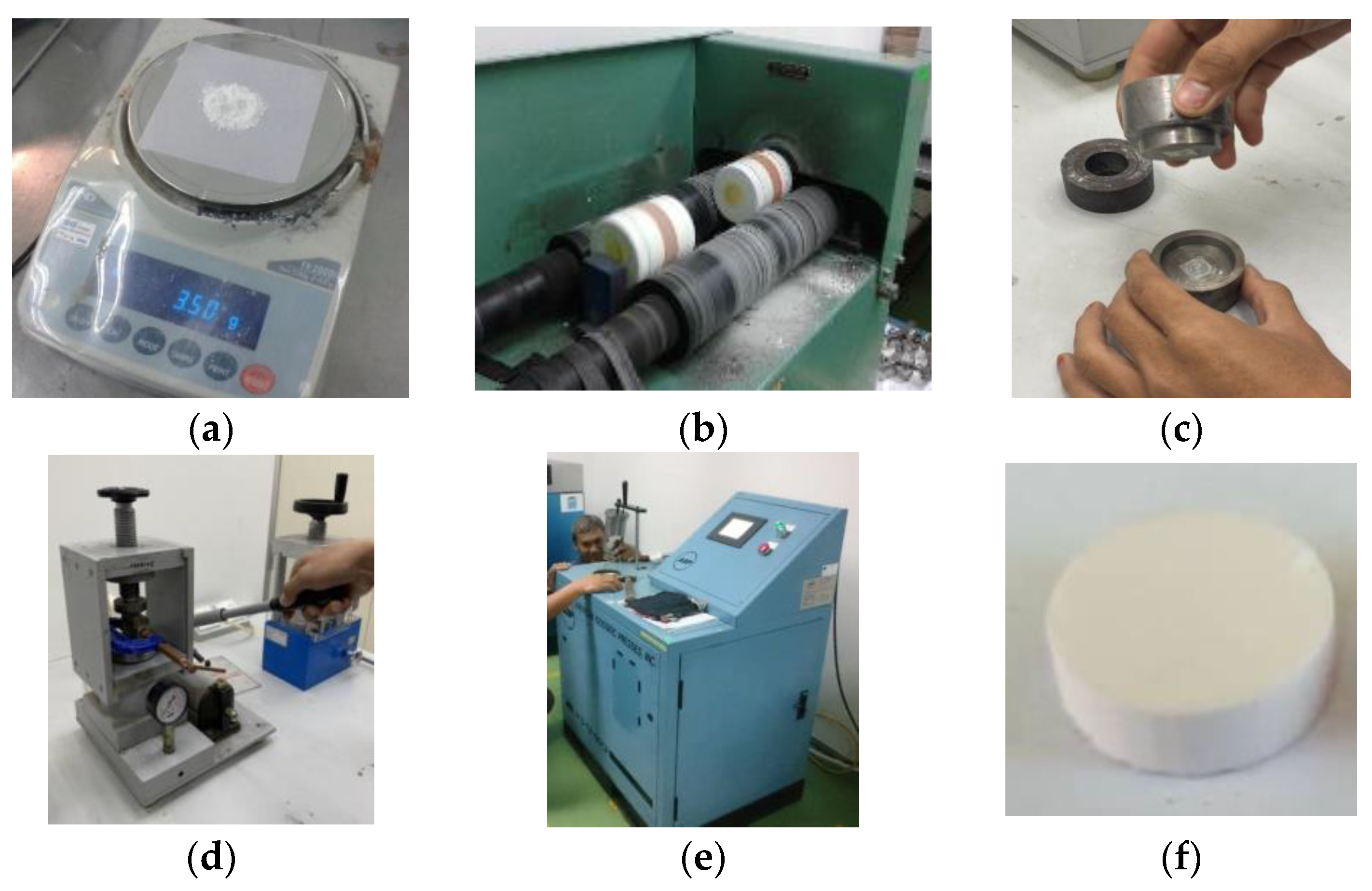
Figure 1a shows the alumina powders used in this study. The properties of alumina used in this study are shown in Table 1. At the initial stage, the powders were weighted for the specified size and ball milled for 12 h to ensure they were agglomeration free, as shown in Figure 1b. These fine powders were poured into the mould, as shown in Figure 1c. The powders then were pressed with a 2-ton Everest Analytical handpress, as shown in Figure 1d. In this study, two shapes of insert were prepared initially, trapezium and round, according to the size of the CNMG 141407 (14 mm length, 14 mm width, and 7 mm thickness) and the RNGN 140700 (14 mm diameter and 7 mm thickness). These compacted inserts were further pressed inside the cold Isostatic press (American Isostatic Presses, model AIP3-12-60CPA) with 350 MPa pressure as shown in Figure 1e. Figure 1f shows the example of an alumina compact prepared according to the required shape.
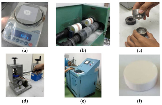
Figure 1.
Manufacturing process of alumina insert. (a) Preparation of the alumina powders. (b) Blending process. (c) Mould preparation. (d) Pressing operation with Everest Analytical hydraulic handpress. (e) Cold isostatic pressing operation with AIP3-12-60CPA American Isostatic Presses. (f) Example of alumina compact prepared according to the required shape.

Table 1.
Properties of alumina powder used in this study.
The compacted powders were sintered at the parameters of 1200–1400 °C and 5–9 h holding time, as shown in Table 2. These temperatures were selected because they are within the range of interparticle bonding acceleration that promotes densification in the alumina’s structural strength [17]. The shrinkage of the sintered powders was analysed by measuring the width, length, and thickness (depth) before and after the sintering operation. The relative density was measured using the “Archimedes” concept based on the referred full alumina density at 3.987 g/cm3. A Scanning Electron Microscope (SEM) was used to observe the microstructural evolution of the sintered samples.
Table 2.
Parameters for the sintering temperature and holding time.
Machining trials of the selected alumina insert were performed by turning AISI 1045 carbon steel. AISI 1045 carbon steel is a typical type of carbon steel, frequently used in cold worked application such as gears, pins, axles, and vices. This type of steel has a potential for high strength and wear resistance applications in major industrial operation [18]. The chemical composition of AISI 1045 steel is shown in Table 3.
Table 3.
Chemical composition of AISI 1045 steel. Data from reference [18].
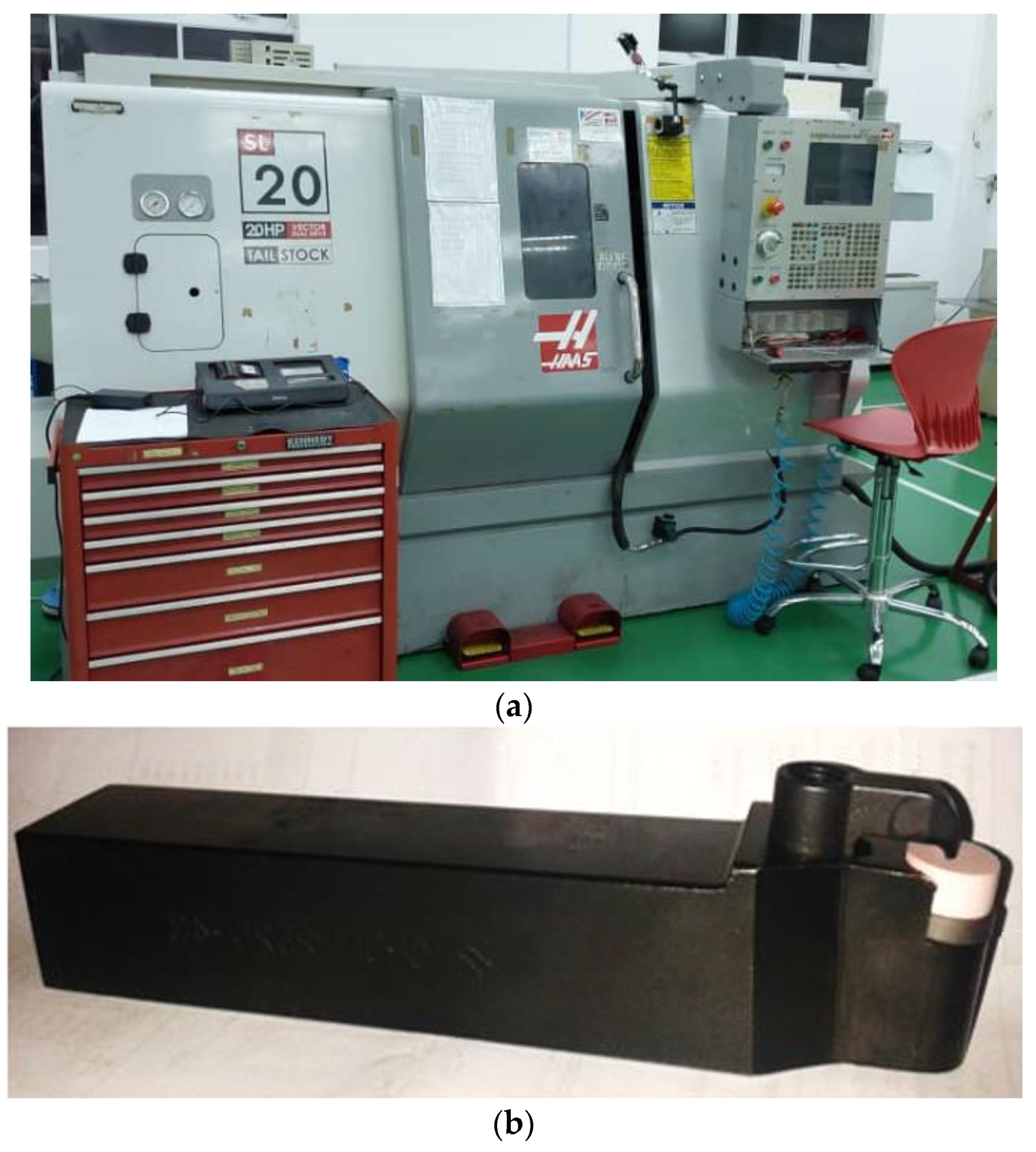
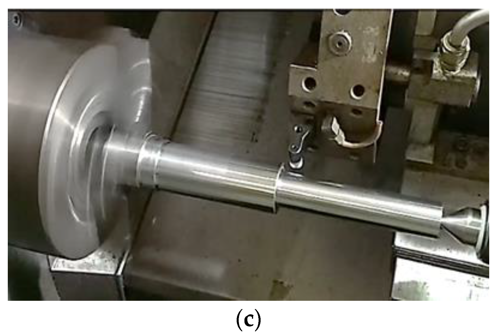
Machining trials were performed according to ISO 3685, which is a standard of tool life testing with a single point turning tools at varying cutting speeds and feed rates, as prescribed in Table 4. The selection of parameters such as the cutting speed, feed rate, and depth of cut was based on the range used by previous researchers as described in [9,16]. A Haas SL-20T CNC lathe machine was used to perform the turning operation, as shown in Figure 2a. The insert was clamped on the CRDN252543 tool holder as shown in Figure 2b. Figure 2c shows the setup for the machining trials.
Table 4.
Machining parameters and input conditions.
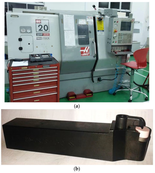

Figure 2.
The equipment for the machining trials. (a) Haas SL-20T CNC lathe machine, (b) alumina insert with CRDN252543 tool holder, and the (c) machining setup inside the CNC machine.
The round cutting tool with the highest density was selected for the machining trial since the edge of this cutting tool was stronger than the trapezium. The tool wear was measured at the flank area by a tool maker microscope, where the period of the tool life was set within 0.3 mm average flank wear.
3. Results
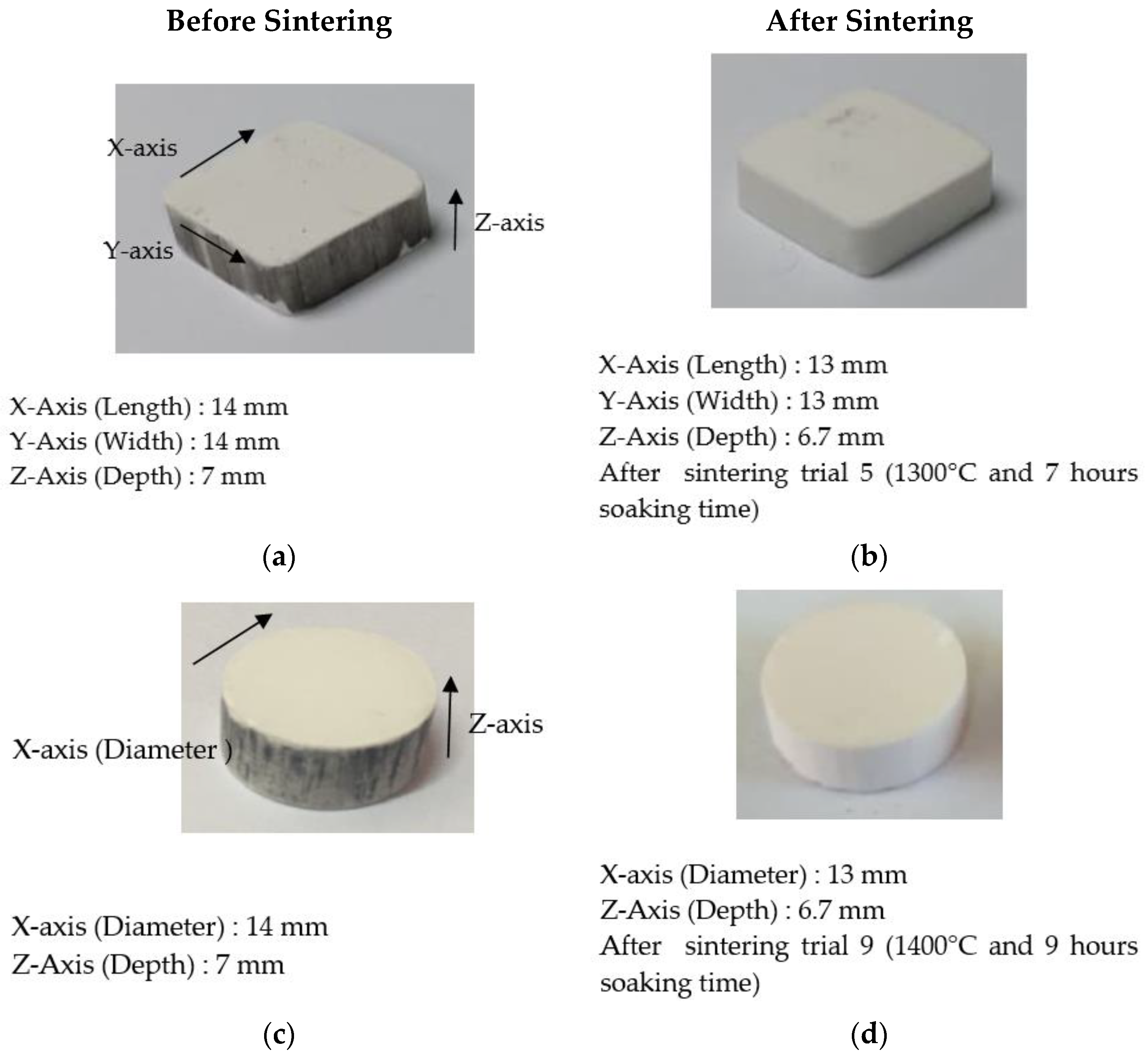
Figure 3 shows the appearance of the compacted alumina insert tool before and after sintering for both the trapezium and round shapes. Significant carbon marks appeared on the sample prior to sintering, most likely as a result of the sliding lubricant inside the mould. After sintering, the carbon marks on the sides of cutting tools diminished, and the colour of the samples slightly changed to clean white.

Figure 3.
The change in the size and appearance of the alumina inserts with a (a) Trapezium shape before sintering, (b) Trapezium shape after sintering, (c) Round shape before sintering and (d) Round shape after sintering.
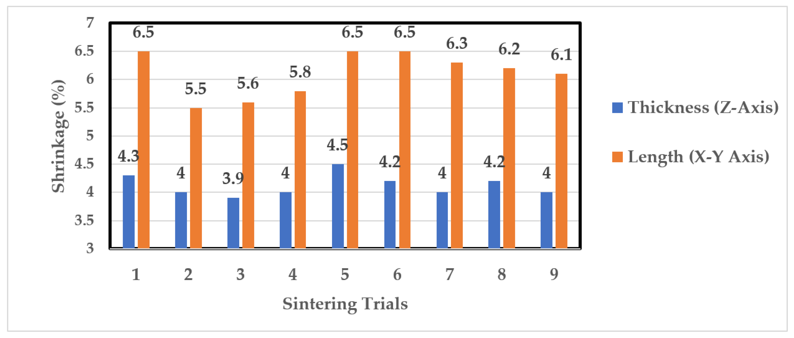
Figure 4 presents the shrinkage variation for an alumina insert with a trapezium shape after sintering with each of the nine sintering conditions listed in Table 1. Throughout the sintering trials, the alumina inserts with the trapezium shape had size reductions of up to 6.5% after sintering. The samples’ lengths (X–Y direction) showed more shrinkage than their thickness (Z direction). This is explained by more gaps or different particle packing along the larger top surface area of 14 mm × 14 mm for the trapezium sample, as compared to each side area (14 mm × 6 mm), which led to a higher tendency of densification along the top surface of the sample [19].

Figure 4.
Distribution of the shrinkage for alumina inserts in the trapezium shape.
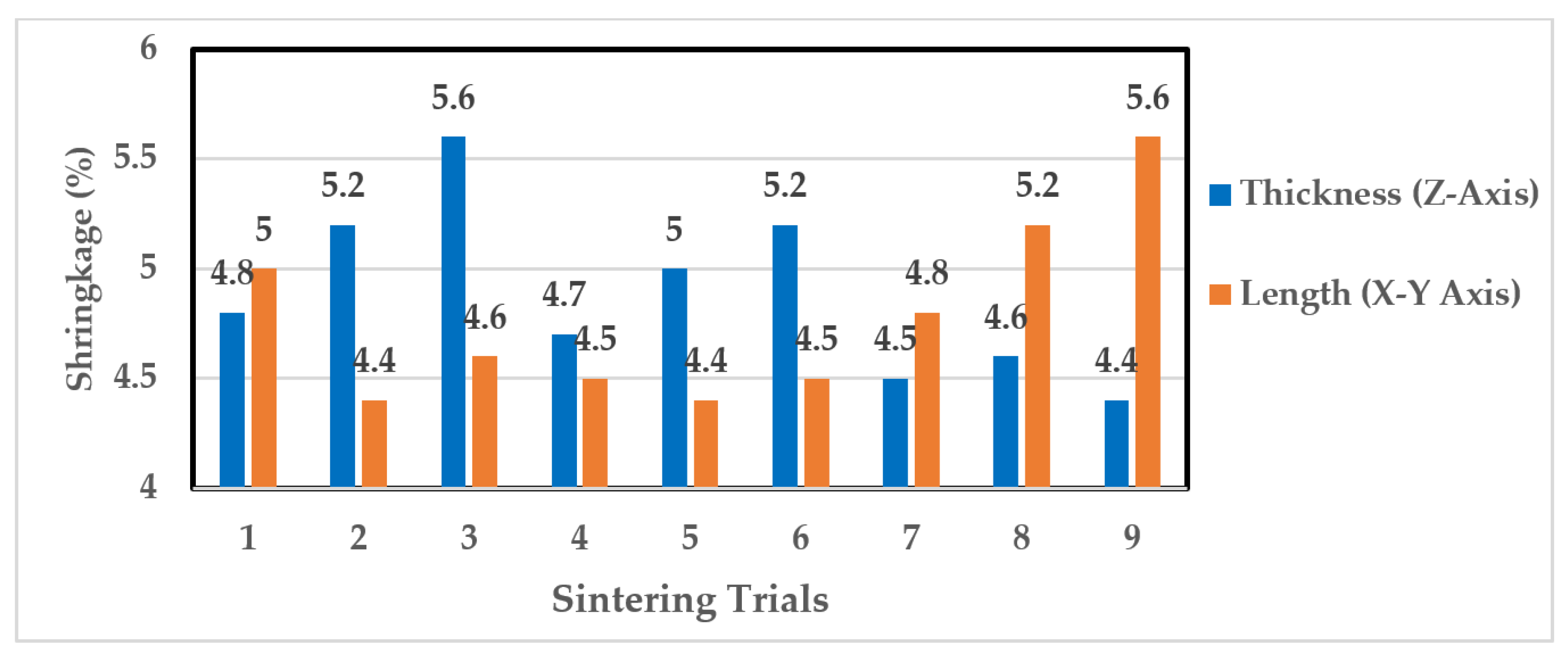
A similar condition was observed when sintering an alumina insert with a round shape. This is shown in Figure 5, where the length of the thickest insert was scattered along 3–6% of the sintering trials. The greatest shrinkage was recorded at 5.6% during sintering trial 9 and sintering trial 3. It can be seen that the samples’ thickness (Z-axis) had more shrinkage than their lengths (X-Y axis) at lower sintering temperatures of 1200 °C and 1300 °C. On the other hand, the length (diameter) had more shrinkage, up to 5.6%, when the temperature increased to 1400 °C. The results from this experiment suggest that the shrinkage rate for the round sample demonstrated nonlinear behaviour probably due to the nonuniform heat transfer or nonuniformity in the local packing density of the particles [20].
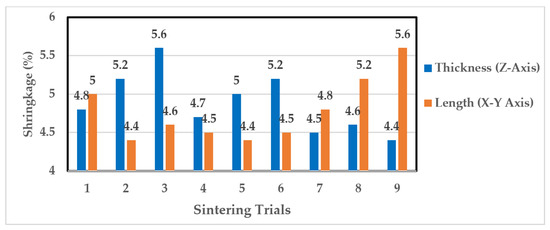
Figure 5.
Distribution of the shrinkage for the alumina inserts in the round shape.
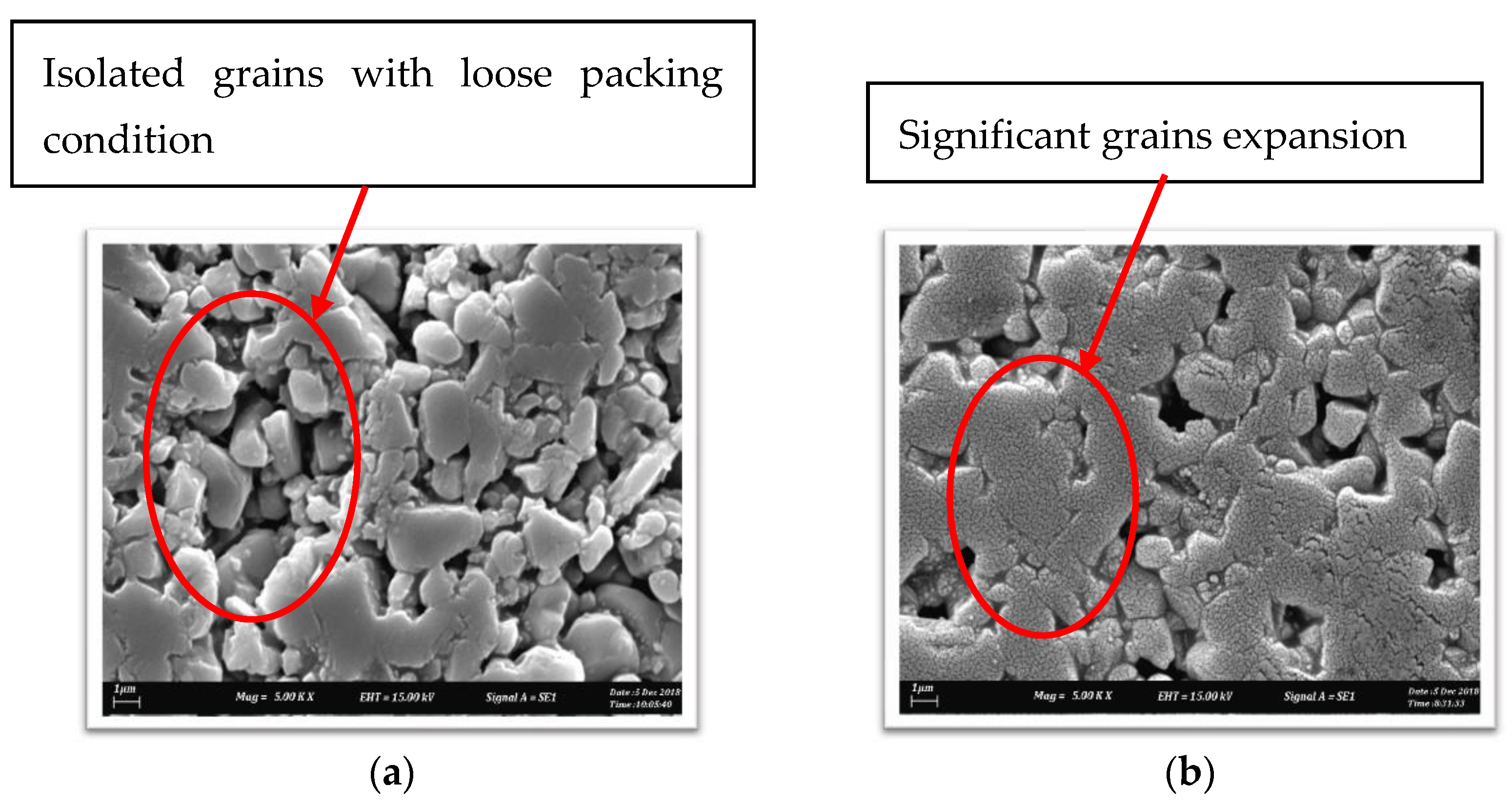
Figure 6 presents a more in-depth examination of the microstructure of the sintered alumina. The particles demonstrated isolated grains where the particles integrated in loose packing condition at the lower sintering temperature of 1200 °C (Figure 6a). Significant grain expansion was observed as the sintering temperature increased to 1400 °C (Figure 6b). This demonstrates that sintering at 1400 °C effectively suppressed the grain growth. In terms of the holding time, Figure 7 shows a comparison of the sintered microstructure from low and high holding times. The alumina clearly showed isolated grains with little sign of particle expansion (Figure 7a). When the holding time reached 9 h, the long heating time imparted high energy to the particles, causing them to expand until the grain size reached its limits (Figure 7b).

Figure 6.
Microstructure of the alumina that was sintered at a (a) sintering temperature of 1200 °C and 5 h soaking time and a (b) sintering temperature of 1400 °C and 5 h soaking time [12].
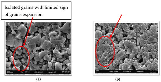
Figure 7.
Microstructure of the alumina that was sintered at a (a) holding time of 5 h and sintering temperature of 1300 °C and a (b) holding time of 9 h and sintering temperature of 1300 °C [12].
The shrinkage of the alumina particles after the sintering was expected due to alumina’s large thermal expansion of 10.3 × 10⁻⁶ °C−1 [21]. During particle packing at high temperatures, three stages of solidification occurred. The first stage began with the transportation of particles to shrink and perform necking between grains. At the intermediate stage, the grains began to expand, and the particles began to interact with one another. Higher sintering temperatures or longer sintering times increased the particle liquidity, forcing them into diffusion at the third stage. Once diffused, the mass centre separation distance between particles can decrease, resulting in sintered particle shrinkage [22,23]. Large shrinkage of the alumina samples means that it requires larger building space for a specific mould to produce accurately sintered products. It is indeed a shortcoming that the alumina samples fabricated in this study had almost nonlinear shrinkage, which caused complicated preparation to produce a precision cutting tool.
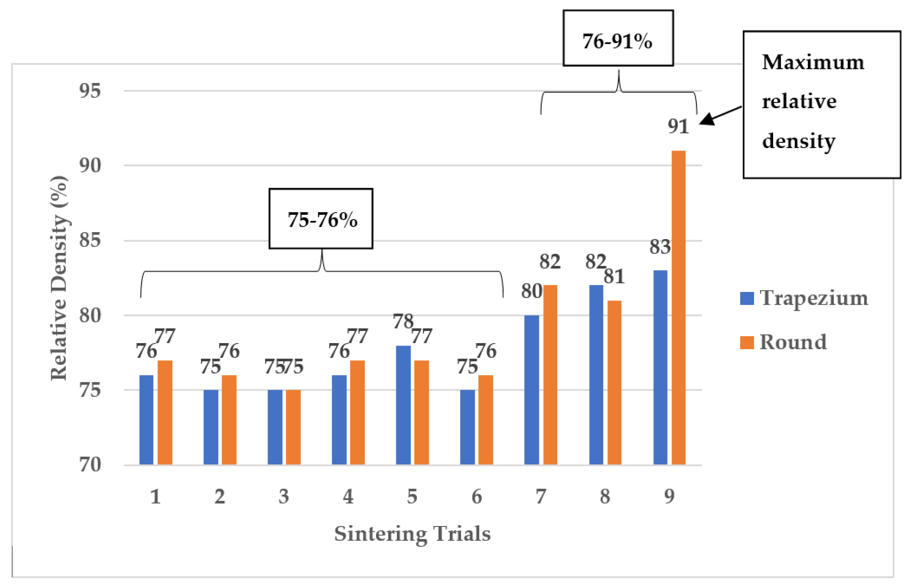
Figure 8 shows the variation in the relative density according to the nine sintering conditions, shown in Table 1. The inserts that were sintered from trials 1 to 6 demonstrated almost constant relative density, which was within the range of 75–76%. The increase in the density was seen when the sintering parameters were changed from trials 7 to 9, which were at 1400 °C. The maximum relative density was increased from 76% to 91.3%. This result, displayed in Figure 8, shows that increasing the holding time and sintering temperature caused particle expansion and, as a result, a reduction in the number of pores trapped between particles. As shown in Figure 6a, when the particles were sintered at a lower temperature of 1200 °C, less heating energy was expended, resulting in significant porosity. The alumina grains expanded to close the gap between particles as the sintering temperature increased to 1400 °C, as shown in Figure 6b. At the higher sintering temperature, additional grain growth facilitated particle diffusion, resulting in a larger contact area at the grain boundaries. This situation could result in interlocking grains that increase the structural toughness of particle packing. When subjected to a cutting load, lower porosity reduces the possibility of stress concentration and grain slipping. As a result, decreasing the porosity of the ceramic structure increased the grain resistance to deformation, resulting in a higher hardness of the sample [9,10,21]. The structure solidified significantly as the density increased, strengthening the interlocking structure between grains. Finally, the structure provided sufficient hardness to function as a cutting tool.

Figure 8.
Distribution of the relative density according to the sintering trials of the alumina inserts.
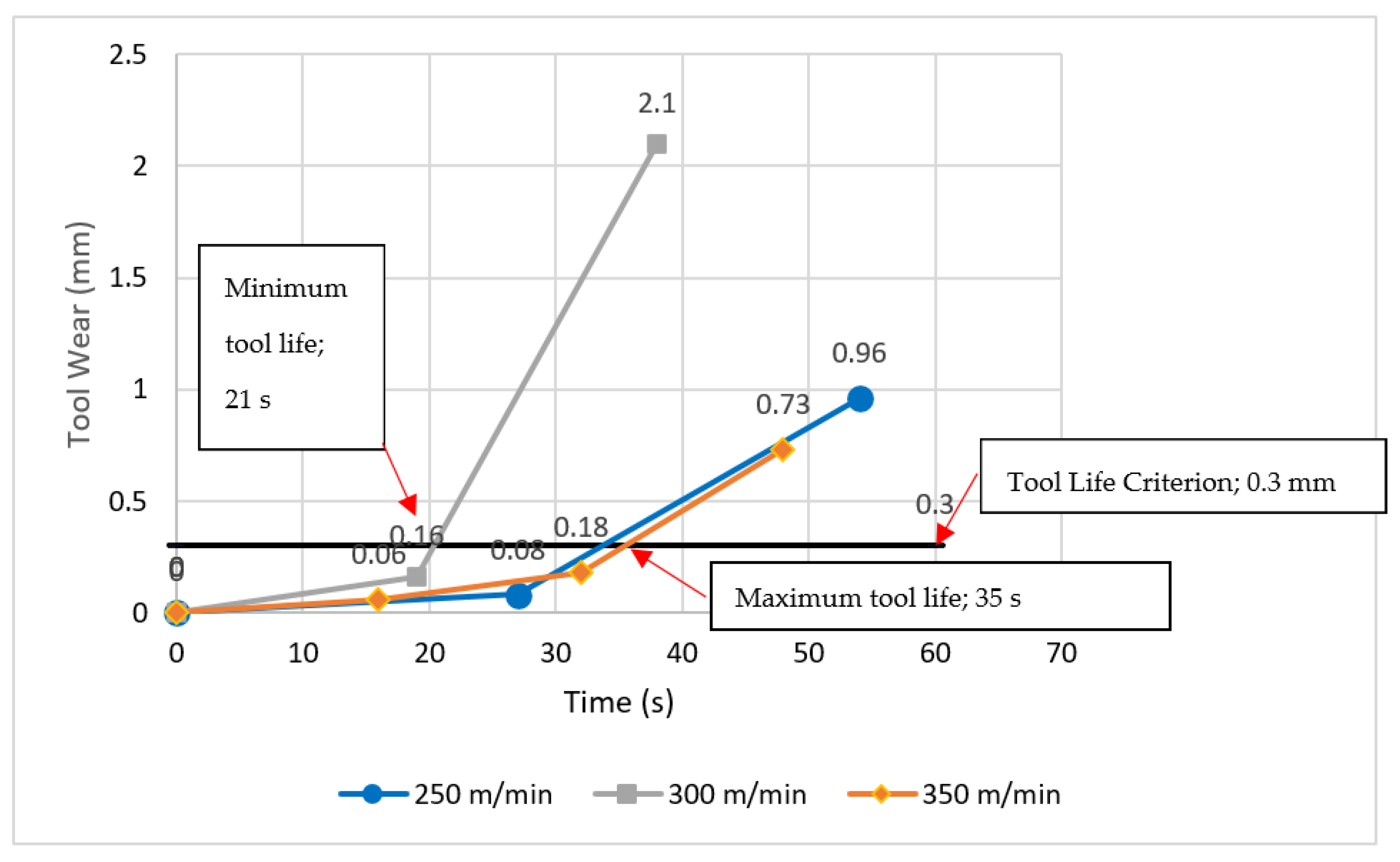
Figure 9 shows a comparison of the tool life for the round alumina inserts fabricated in this study. According to Figure 9, the lowest tool life was recorded at a cutting speed of 300 m/min during a 21 s machining period. A higher tool life was recorded at the cutting speed of 250 m/min with a 33 s machining duration, and the longest tool life was recorded at a cutting speed of 350 m/min during a 35 s machining period.

Figure 9.
Comparison of the tool life at various cutting speeds at the feed rate of 0.15 mm/rev.
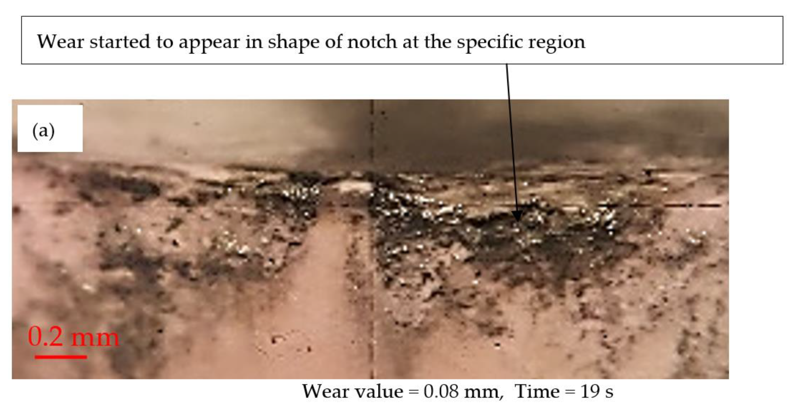
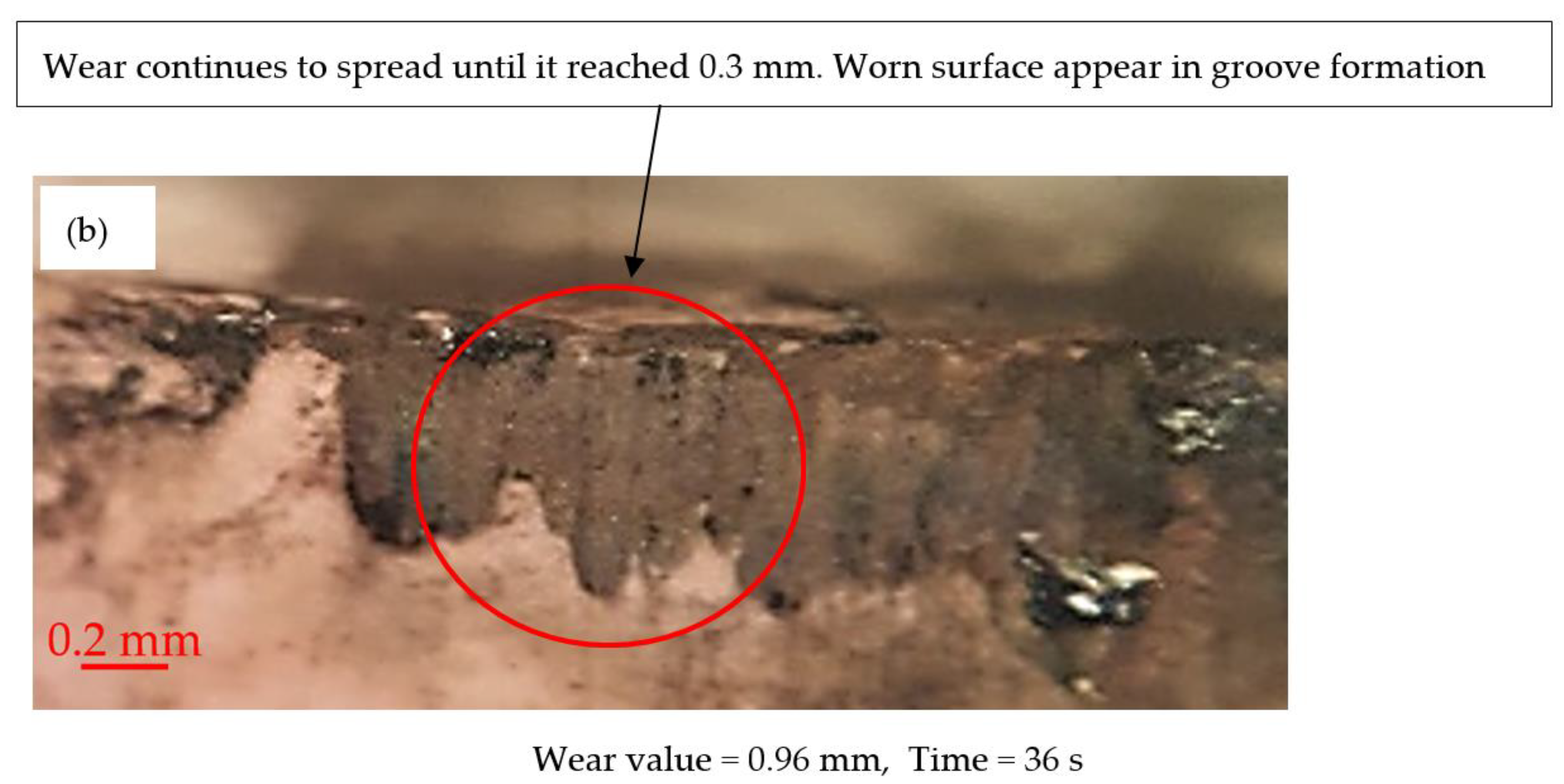
Figure 10 shows the wear development of alumina inserts at a 250 m/min cutting speed and a 0.15 mm/rev feed rate. The wear initiated at the flank area, where some portion of wear started to appear in the shape of notch at the specific region, as shown in Figure 10a. Further machining revealed that the wear spiked rapidly until it reached 0.96 mm within a short time of machining, as shown in Figure 10b. This demonstrates how the brittle nature of alumina was easily fractured from the first contact of the cutting tool with the workpiece material AISI 1045 carbon steel.


Figure 10.
Flank wear progression of the alumina insert (200 m/min cutting speed, 0.15 mm/rev and 0.5 mm depth of cut) at a (a) 19 s cutting period and a (b) 36 s cutting period.
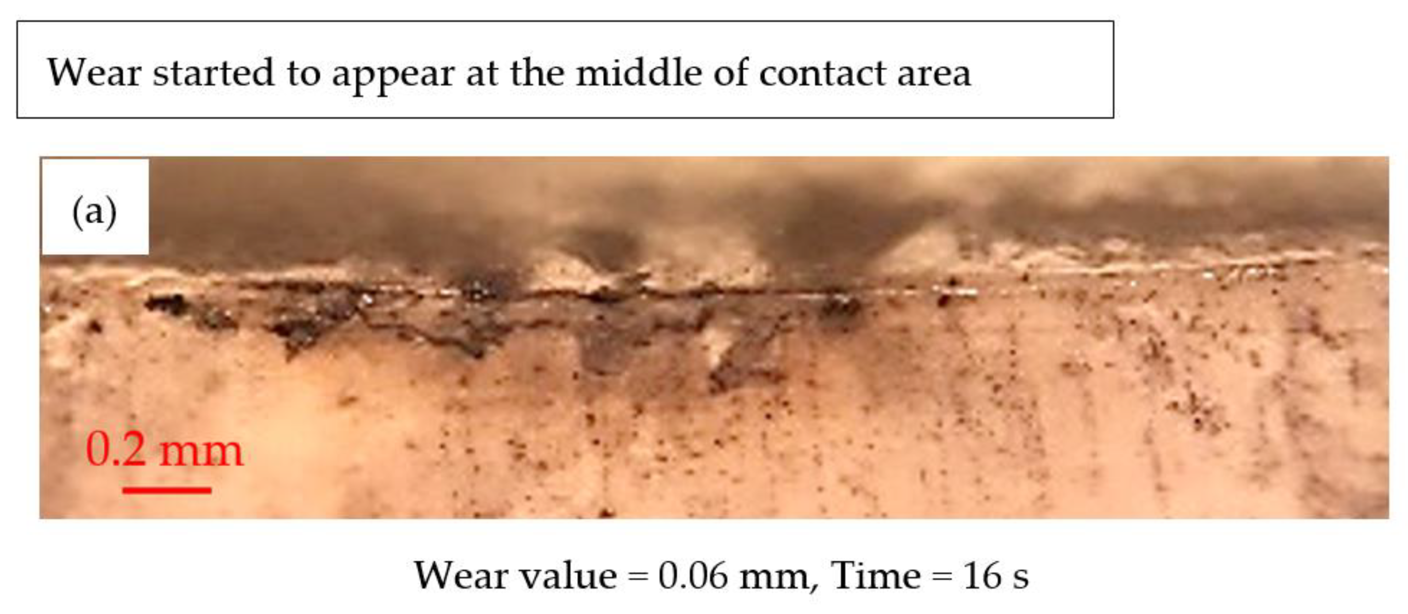
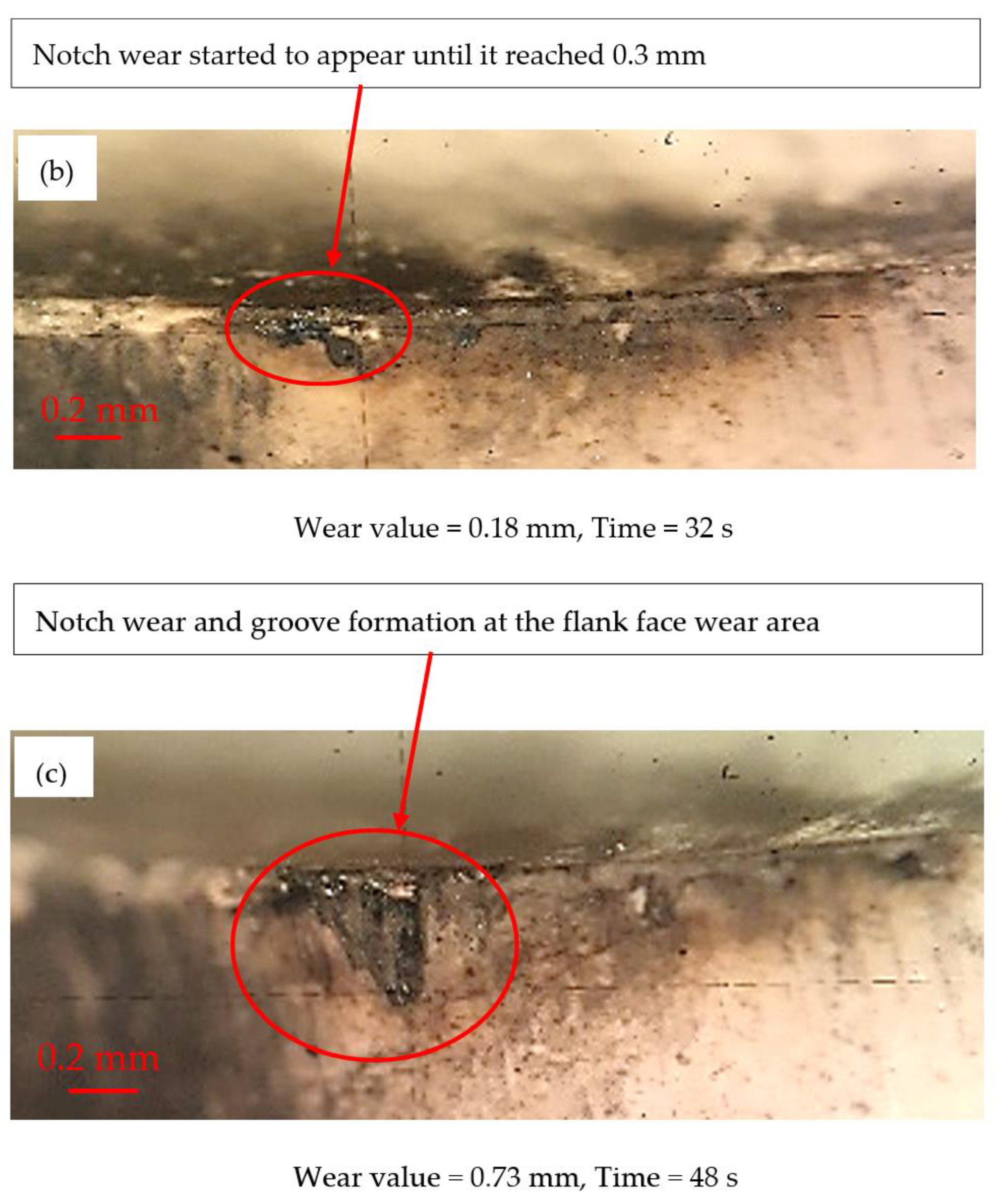
Figure 11 shows the wear development of alumina inserts at a 350 m/min cutting speed and a 0.15 mm/rev feed rate. As shown in Figure 11a, the early wear development of the alumina insert revealed the formation of flank wear that was concentrated in the middle contact area. As the machining time increased to 32 s, significant notch wear was generated in the central region of the flank wear area, as shown in Figure 11b. The progression of wear in the concentrated region indicated that the alumina insert could not withstand the load due to its low shock resistance. Further machining after 48 s as shown in Figure 11c revealed the formation of notch wear at 0.76 mm, which exceeded the acceptable wear of 0.3 mm. This indicates that material was lost at the cutting tool’s edge, resulting in an uneven contact area, higher cutting force, friction, vibration, and accelerated tool wear. These flaws are due to alumina’s intrinsic low toughness, which allows for catastrophic failure and crack growth within a short period of machining [24].
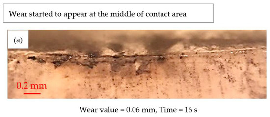

Figure 11.
Flank wear progression of the alumina insert (350 m/min cutting speed, 0.15 mm/rev and 0.5 mm depth of cut) at a (a) 16 s cutting period, (b) 32 s cutting period and a (c) 48 s cutting period.
Further inspection of the wear region, pictured in Figure 10b and Figure 11c, showed the formation of grooves at the flank face of the wear area, in addition to a severe notch-shaped flank wear. The formation of such grooves reflected the abrasive wear at the contact region. When the detached ceramic particles trapped and rolled on the contact interface, the groove was formed. Furthermore, some hard particles from the workpiece materials may become detached, trapped, and rolled at the contact interfaces to form parallel ridges. The groove that formed inside the notch wear area allowed molten steel to attach and promote adhesive wear, which could hasten the cutting tool wear. Accumulation of groove formation results in significant material loss at the tool edge, facilitating easy fracture at the cutting tool’s edge [25,26,27].
4. Conclusions
The fabrication of an alumina based cutting tool was carried out. The effective sintering parameters were analysed based on the density and shrinkage. Machining trials were performed to determine the capability of newly fabricated alumina cutting tool in machining with AISI 1045 steel. From the study, the following conclusions were derived:
- The sample with a trapezium shape demonstrated more shrinkage at the top surface (X–Y axis) as compared to the round shape. The larger top surface area that was exposed to the sintering heat provided more grain expansion, densification, and porosity reduction in the alumina’s structure.
- The maximum relative density of 91.3% was obtained when using a sintering parameter of 1400 °C and a holding time of 9 h. With the higher density of the ceramic compact, it was expected that the particles were packed close to each other with a lower porosity inside the structure.
- The fabricated alumina cutting tools exhibited a tool life of 35 s, which indicated that the cutting tool was capable of withstanding a high mechanical and thermal load during machining with AISI 1045 carbon steel.
- The dominant wear mechanisms for the fabricated alumina cutting tool when machined with AISI 1045 carbon steel appeared to be notch wear, abrasive wear, and chipping.
This research enables more accurate fabrication of alumina-based cutting tools by determining the relationship between the sintering parameters and density as well as the shrinkage. This will facilitate better understanding of the contact condition during machining, which will lead to the optimization of tool life with controlled failure modes and wear mechanisms.
Author Contributions
Conceptualization, A.A.A. and H.A.B.; methodology, U.A.A. and H.A.B.; resources, S.G.H. and Z.A.; writing—original draft preparation, L.H.P., M.F.M. and H.A.B.; writing—review and editing, L.H.P., M.F.M. and H.A.B.; supervision, U.A.A. and N.A.W.; funding acquisition, M.B.A. and U.A.A.; All authors have read and agreed to the published version of the manuscript.
Funding
This research was funded by the grant FRGS/1/2020/FTKMP-CARE/F00438.
Data Availability Statement
Not applicable.
Acknowledgments
The authors are grateful to the Universiti Teknikal Malaysia Melaka (UTeM) and the Ministry of Higher Education, Malaysia for supporting this work.
Conflicts of Interest
The authors declare no conflict of interest.
References
- Wahab, N.; Inatsugu, Y.; Kubota, S.; Kim, S.; Sasahara, H. An integral method to determine workpiece flow stress and friction characteristics in metal cutting. Int. J. Autom. Technol. 2015, 9, 775–781. [Google Scholar] [CrossRef]
- Xie, W.; Fang, F. Effect of tool edge radius on material removal mechanism in atomic and close-to-atomic scale cutting. Appl. Surf. Sci. 2020, 504, 144451. [Google Scholar] [CrossRef]
- Liu, C.; He, Y.; Wang, Y.; Li, Y.; Wang, S.; Wang, L.; Wang, Y. Effects of process parameters on cutting temperature in dry machining of ball screw. ISA Trans. 2020, 101, 493–502. [Google Scholar] [CrossRef] [PubMed]
- Dogra, M.; Sharma, V.S.; Dureja, J. Effect of tool geometry variation on finish turning—A Review. J. Eng. Sci. Technol. Rev. 2011, 4, 1–13. [Google Scholar] [CrossRef]
- Sarikaya, M.; Kumar, G.M.; Tomaz, I.; Danish, M.; Mia, M.; Rubaiee, S.; Jamil, M.; Danil, Y.P.; Khanna, N. Cooling techniques to improve the machinability and sustainability of light-weight alloys: A state-of-the-art review. J. Manuf. Process. 2021, 62, 179–201. [Google Scholar] [CrossRef]
- Manshor, H.; Azhar, A.Z.A.; Rashid, R.A.; Sulaiman, S.; Abdullah, E.C.; Ahmad, Z.A. Effects of Cr2O3 addition on the phase, mechanical properties, and microstructure of zirconia-toughened alumina added with TiO2 (ZTA–TiO2) ceramic composite. Int. J. Refract. Hard. Met. 2016, 61, 40–45. [Google Scholar] [CrossRef]
- Filipović, S.; Obradović, N.; Marković, S.; Mitrić, M.; Balać, I.; Đorđevićd, A.; Pavlović, V. The effect of ball milling on properties of sintered manganese-doped alumina. Adv. Powder Technol. 2019, 30, 2533–2540. [Google Scholar] [CrossRef]
- Mondal, B.; Mandal, N.; Doloi, B. Development of Ce-PSZ-/Y-PSZ-toughened alumina inserts for high-speed machining steel. Int. J. Appl. Ceram. Technol. 2014, 11, 228–239. [Google Scholar] [CrossRef]
- Singh, B.K.; Mondal, B.; Mandal, N. Machinability evaluation and desirability function optimization of turning parameters for Cr2O3 doped zirconia toughened alumina (Cr-ZTA) cutting insert in high speed machining of steel. Ceram. Int. 2016, 42, 3338–3350. [Google Scholar] [CrossRef]
- Manshor, H.; Abdullah, E.C.; Azhar, A.Z.A.; Sing, Y.W.; Ahmad, Z.A. Microwave sintering of zirconia-toughened alumina (ZTA)-TiO2-Cr2O3 ceramic composite: The effects on microstructure and properties. J. Alloys Compd. 2017, 722, 458–466. [Google Scholar] [CrossRef]
- Lóh, N.J.; Simão, L.; Jiusti, J.; Arcaro, S.; Raupp-Pereira, F.; De Noni, A., Jr.; Montedo, O.R.K. Densified alumina obtained by two-step sintering: Impact of the microstructure on mechanical properties. Ceram. Int. 2020, 46, 12740–12743. [Google Scholar] [CrossRef]
- Hadzley, A.B.; Afuza, A.A.; Faiz, M.M.; Azlan, U.A.A.; Hassan, M.H.; Nursyasya, S. Investigation of properties of alumina based cutting tool under different sintering temperature and soaking time. In Proceedings of the International Symposium of Manufacturing and Industrial Engineering (MIE 2019), Melaka, Malaysia, 14–16 December 2019. [Google Scholar]
- Zadorozhnaya, O.Y.; Khabas, T.A.; Tiunova, O.V.; Malykhin, S.E. Effect of grain size and amount of zirconia on the physical and mechanical properties and the wear resistance of zirconia-toughened alumina. Ceram. Int. 2020, 46, 9263–9270. [Google Scholar] [CrossRef]
- Sktani, Z.D.I.; Rejab, N.A.; Ahmad, Z.A. Tougher and harder zirconia toughened alumina (ZTA) composites through in situ microstructural formation of LaMgAl11O19. Int. J. Refract. Met. Hard Mater. 2019, 79, 60–68. [Google Scholar] [CrossRef]
- Shah, D.; Bhavsar, S. Effect of Tool Nose Radius and Machining Parameters on Cutting Force, Cutting Temperature and Surface Roughness—An Experimental Study of Ti-6Al-4V (ELI). Mater. Today Proc. 2020, 22 Pt 4, 1977–1986. [Google Scholar] [CrossRef]
- Adam, A.A.; Hadzley, A.B.; Anis, A.A.; Norfauzi, T.; Umar, A.A.; Herawan, S.G. Fabrication and Wear Behavior of Alumina Based Cutting Tools on Machining AISI 1045. In Proceedings of the 7th International Conference and Exhibition on Sustainable Energy and Advanced Materials (ICE-SEAM 2021), Melaka, Malaysia, 23 November 2021; pp. 141–144. [Google Scholar]
- Kalemtas, A. Effect of the sintering temperature on the fabrication of alumina beads. Mater. Sci. Res. India 2019, 16, 125–135. [Google Scholar] [CrossRef]
- Moon, S.-H.; Lee, C.-M. A study on the machining characteristics using plasma assisted machining of AISI 1045 steel and Inconel 718. Int. J. Mech. Sci. 2018, 142–143, 595–602. [Google Scholar] [CrossRef]
- Chen, S.; Wang, C.-S.; Zheng, W.; Wu, J.-M.; Yan, C.-Z.; Shi, Y.-S. Effects of particle size distribution and sintering temperature on properties of alumina mold material prepared by stereolithography. Ceram. Int. 2022, 48, 6069–6077. [Google Scholar] [CrossRef]
- Elsen, S.R.; Ramesh, T. Shrinkage characteristics studies on conventional sintered zirconia toughened alumina using computed tomography imaging technique. Int. J. Refract. Met. Hard Mater. 2016, 54, 383–394. [Google Scholar] [CrossRef]
- Azhar, A.Z.A.; Choong, C.L.; Mohamed, H.; Ratnam, M.M.; Ahmad, Z.A. Effects of Cr2O3 addition on the mechanical properties, microstructure and wear performance of zirconia-toughened-alumina (ZTA) cutting inserts. J. Alloys Compd. 2012, 513, 91–96. [Google Scholar] [CrossRef]
- Galusek, D.; Ghillányová, K.; Sedláček, J.; Kozánková, J.; Šajgalík, P. The influence of additives on microstrucutre of sub-micron alumina ceramics prepared by two-stage sintering. J. Eur. Ceram. Soc. 2012, 32, 1965–1970. [Google Scholar] [CrossRef]
- Li, H.; Liu, Y.; Colombo, P.; Li, W.; Liu, Y.; Hu, K.; Lu, Z. The influence of sintering procedure and porosity on the properties of 3D printed alumina ceramic cores. Ceram. Int. 2021, 47, 27668–27676. [Google Scholar] [CrossRef]
- Yin, Z.; Huang, C.; Yuan, J.; Zou, B.; Liu, H.; Zhu, H. Cutting performance and life prediction of an Al2O3/TiC micro–nano-composite ceramic tool when machining austenitic stainless steel. Ceram. Int. 2015, 41, 7059–7065. [Google Scholar] [CrossRef]
- Liu, C.; Sun, J. Effect of load on friction and wear behaviors of alumina matrix ceramic guideway materials. J. Alloys Compd. 2018, 743, 268–273. [Google Scholar] [CrossRef]
- Wang, D.; Xue, C.; Cao, Y.; Zhao, J. Fabrication and cutting performance of an Al2O3/TiC/TiN ceramic cutting tool in turning of an ultra-high-strength steel. Int. J. Adv. Manuf. Technol. 2017, 9, 1967–1969. [Google Scholar] [CrossRef]
- Abd Maleque, M.; Harina, L.; Bello, K.; Azwan, M.; Rahman, M.M. Tribological properties of surface modified Ti-6Al-4V alloy under lubricated condition using Taguchi approach. J. Tribol. 2017, 17, 15–28. [Google Scholar]

Publisher’s Note: MDPI stays neutral with regard to jurisdictional claims in published maps and institutional affiliations. |
© 2022 by the authors. Licensee MDPI, Basel, Switzerland. This article is an open access article distributed under the terms and conditions of the Creative Commons Attribution (CC BY) license (https://creativecommons.org/licenses/by/4.0/).