
Numerical Analysis for Wetting Behaviors of an Oil Jet Lubricated Spur Gear


Abstract
:1. Introduction
2. Theoretical Model
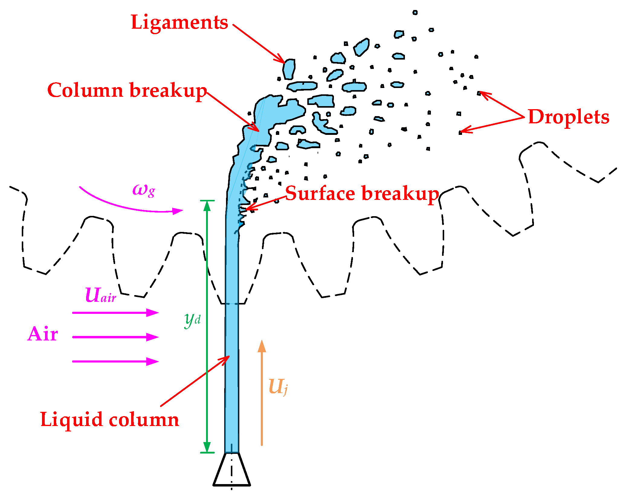
2.1. Oil Jet in Crossflow
2.2. Oil Jet Resistance Torque
2.3. Windage Resistance Torque
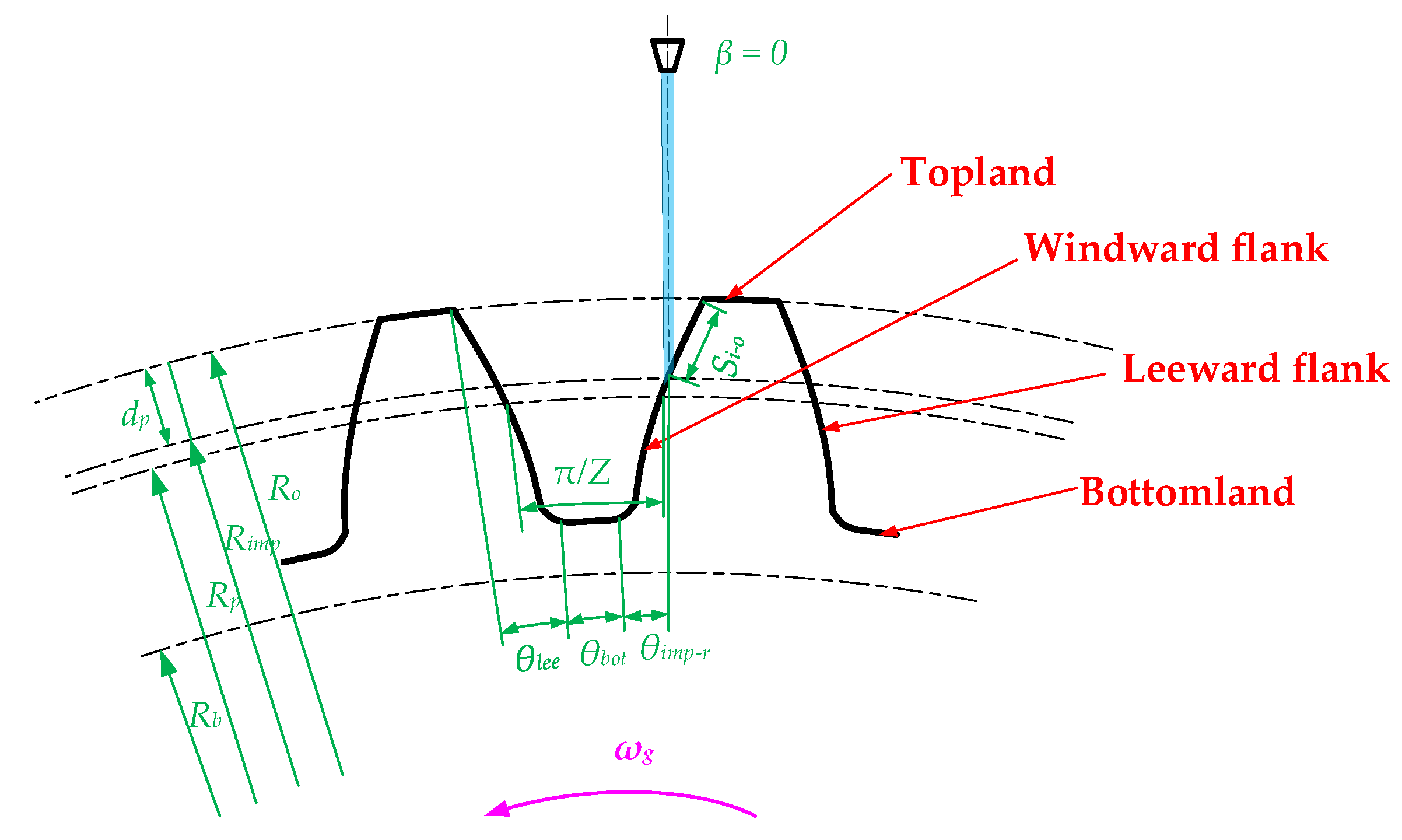
2.4. Wetted Length Tooth Surface
3. CFD Modeling
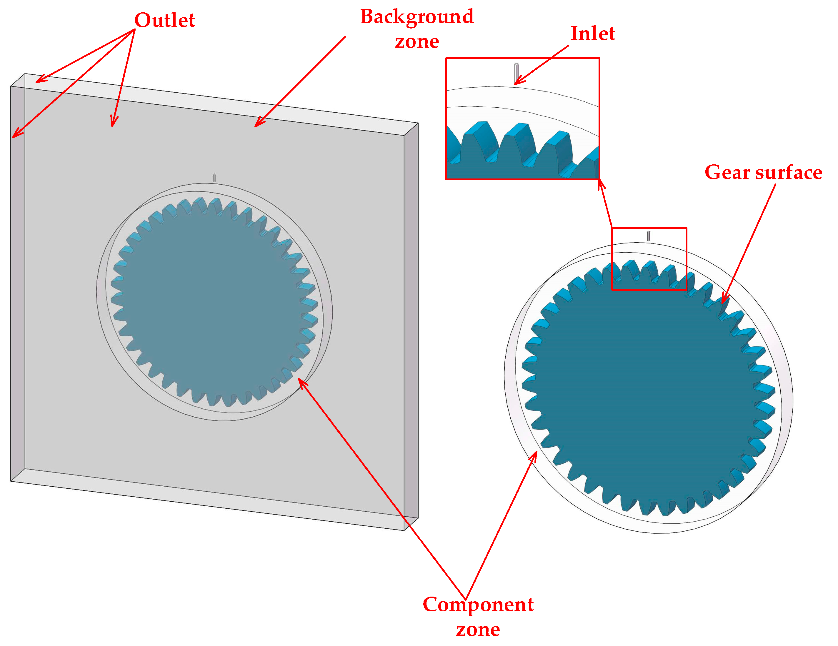
3.1. Geometry
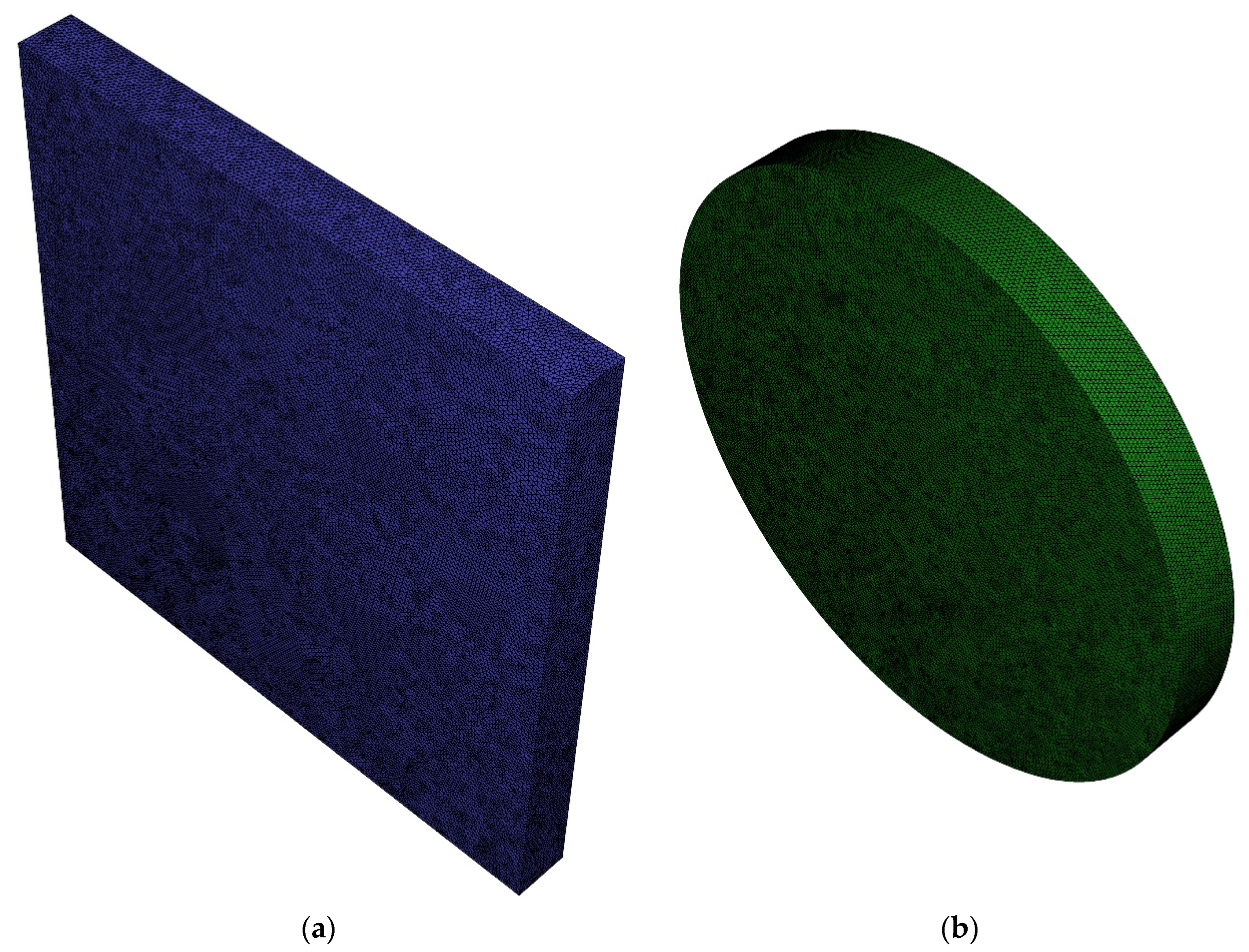
3.2. Computational Domains and Numerical Setup
4. Results and Discussion
4.1. Comparison with Experimental Findings
4.2. Prediction of Oil Jet Loss
4.3. Wetting Behavior
5. Conclusions
Author Contributions
Funding
Acknowledgments
Conflicts of Interest
Nomenclature
| Afilm | wetted surface of the oil film on the windward side [m2] |
| bg | gear width [m] |
| Cf | nondimensional number of torque coefficient on the front/rear faces |
| Ct | nondimensional number of torque coefficient on the gear teeth |
| Cw | nondimensional number of windage resisting torque |
| dp | gear pitch diameter [m] |
| dimp | impingement depth [m] |
| dj | jet diameter [m] |
| F | flying distance of the oil jet [m] |
| inv αP, inv αA | involute function |
| lo | distance from the nozzle exit to the gear outside diameter [m] |
| n | rotating speed of the gear [r/min] |
| ni,mi | constant coefficient. i = 1, for laminar flows; i = 2, for turbulent flows |
| Pw | windage power loss [W] |
| q | oil to air momentum ratio |
| Q | rate of oil flow [m3/s] |
| R* | critical radius to separate the laminar and turbulent flows [m] |
| Ra | outside radius [m] |
| Rb | base radius [m] |
| Re* | critical Reynolds number to separate the laminar and turbulent flows |
| Rn | radius of the nozzle exit [m] |
| Ro | outside radius [m] |
| Rp | pitch radius [m] |
| si-o | arc length of the oil film [m] |
| arc length of the oil film per unit time [m/s] | |
| T0 | oil jet resistance torque (β = 0) [N⋅m] |
| Tj | oil jet resistance torque [N⋅m] |
| Tw | windage resisting torque [N⋅m] |
| Uair | circumferential airflow velocity [m/s] |
| Uj | oil jet velocity [m/s] |
| Up | pitch line velocity [m/s] |
| Wecf | Weber number |
| Wfilm | width of the film [m] |
| XA | profile shift coefficient |
| yd | calculated travel distance of the oil flow [m] |
| Z | teeth number |
| αP,αA | pressure angle at the pitch and outside circle, respectively [rad] |
| β | oil jet angle [rad] |
| θbottom | gear angle of the bottomland [rad] |
| θimp | gear angle between the base circle and the circle of the impingement point [rad] |
| θimp-r | gear angle between the root radius and the impingement point on the windward side [rad] |
| θj | gear angle between the base circle and an arbitrary point j on the gear surface [rad] |
| θlee | gear angle of the leeward side [rad] |
| θo | gear angle between the base circle and outside circle [rad] |
| θp | gear angle between the base circle and pitch circle [rad] |
| θr | gear angle between the base circle and root circle [rad] |
| θtot | total gear angle rotating from the time the oil flow reaches the addendum until hits on the gear [rad] |
| μoil | oil viscosity [Pa⋅s] |
| ξ | reduction factor |
| ρair | air density [kg/m3] |
| ρoil | oil density [kg/m3] |
| σ | surface tension coefficient of oil [N/m] |
| ωg | angular velocity of the gear [rad/s] |
References
- Handschuh, R.R.; Kilmain, C.J. Efficiency of High-Speed Helical Gear Trains; Technical Report NASA/TM-2003-212222; ARL-TR-2968; Cleveland OH Glenn Research Center: Cleveland, OH, USA, 2003. [Google Scholar]
- Eastwick, C.N.; Johnson, G. Gear windage: A review. J. Mech. Des. 2008, 130, 034001. [Google Scholar] [CrossRef]
- Seetharaman, S.; Kahraman, A. Load-independent spin power losses of a spur gear pair: Model formulation. J. Tribol. 2009, 131, 022201. [Google Scholar] [CrossRef]
- Hu, X.; Wang, A.; Li, P.; Wang, J. Influence of dynamic attitudes on oil supply for bearings and churning power losses in a splash lubricated spiral bevel gearbox. Tribol. Int. 2021, 159, 106951. [Google Scholar] [CrossRef]
- Boni, J.B.; Changenet, C.; Ville, F. Analysis of flow regimes and associated sources of dissipation in splash lubricated planetary gear sets. J. Tribol. 2021, 143, 111805. [Google Scholar] [CrossRef]
- Quiban, R.; Changenet, C.; Marchesse, Y.; Ville, F. Experimental investigations about the power loss transition between churning and windage for spur gears. J. Tribol. 2021, 143, 024501. [Google Scholar] [CrossRef]
- Maccioni, L.; Concli, F. Computational fluid dynamics applied to lubricated mechanical components: Review of the approaches to simulate gears, bearings, and pumps. Appl. Sci. 2020, 10, 8810. [Google Scholar] [CrossRef]
- Talbot, D.; Kahraman, A.; Seetharaman, S. A helical gear pair pocketing power loss model. J. Tribol. 2014, 136, 021105. [Google Scholar] [CrossRef]
- Ruzek, M.; Marchesse, Y.; Ville, F.; Velex, P. Windage power loss reductions in high-speed gear pairs. Forsch. Ing. 2019, 83, 387–392. [Google Scholar] [CrossRef]
- Ariura, Y.; Ueno, T.; SunAGA, T.; Sunamoto, S. The lubricant churning loss in spur gear systems. Bull. JSME 1973, 16, 881–892. [Google Scholar] [CrossRef]
- Chaari, F.; Romdhane, M.B.; Baccar, W.; Fakhfakh, T.; Haddar, M. Windage power loss in spur gear sets. WSEAS Trans. Appl. Theor. Mech. 2012, 7, 159–168. [Google Scholar]
- Concli, F. Thermal and efficiency characterization of a low-backlash planetary gearbox: An integrated numerical-analytical prediction model and its experimental validation. Proc. Inst. Mech. Eng. Part J J. Eng. Tribol. 2016, 230, 996–1005. [Google Scholar] [CrossRef]
- Mastrone, M.N.; Hartono, E.A.; Chernoray, V.; Concli, F. Oil distribution and churning losses of gearboxes: Experimental and numerical analysis. Tribol. Int. 2020, 151, 106496. [Google Scholar] [CrossRef]
- Concli, F.; Gorla, C. Analysis of the power losses in geared transmissions–measurements and CFD calculations based on open source codes. In Proceedings of the International Gear Conference 2014, Lyon, France, 26–28 August 2014; Elsevier Science & Technology: Amsterdam, The Netherlands, 2014. [Google Scholar] [CrossRef]
- Akin, L.S. An interdisciplinary lubrication theory for gears (with particular emphasis on the scuffing mode of failure). J. Eng. Ind. 1973, 95, 1178–1195. [Google Scholar] [CrossRef]
- Dai, Y.; Jia, J.; Ouyang, B.; Bian, J. Determination of an optimal oil jet nozzle layout for helical gear lubrication: Mathematical modeling, numerical simulation, and experimental validation. Complexity 2020, 2020, 2187027. [Google Scholar] [CrossRef]
- Zhu, X.; Dai, Y.; Ma, F.; Ouyang, B. Mathematical modeling and numerical simulation for determining an optimized oil jet layout for spiral bevel gear lubrication. Proc. Inst. Mech. Eng. Part J J. Eng. Tribol. 2021, 235, 611–628. [Google Scholar] [CrossRef]
- Dai, Y.; Ma, F.; Zhu, X.; Su, Q.; Hu, X. Evaluation and optimization of the oil jet lubrication performance for orthogonal face gear drive: Modelling, simulation and experimental validation. Energies 2019, 12, 1935. [Google Scholar] [CrossRef] [Green Version]
- Zhu, X.; Dai, Y.; Ma, F. CFD modelling and numerical simulation on windage power loss of aeronautic high-speed spiral bevel gears. Simul. Model. Pract. Theory 2020, 103, 102080. [Google Scholar] [CrossRef]
- Zhu, X.; Dai, Y.; Ma, F. On the estimation of the windage power losses of spiral bevel gears: An analytical model and CFD investigation. Simul. Model. Pract. Theory 2021, 110, 102334. [Google Scholar] [CrossRef]
- Liu, J.; Ni, H.; Xu, Z.; Pan, G. A simulation analysis for lubricating characteristics of an oil-jet lubricated ball bearing. Simul. Model. Pract. Theory 2021, 113, 102371. [Google Scholar] [CrossRef]
- Karaca, H.D.; Ozen, G.D.; Kasnakoglu, C. Nonlinear modelling and control of the flow over aerofoils using CFD simulations. Simul. Model. Pract. Theory 2016, 67, 29–43. [Google Scholar] [CrossRef]
- Concli, F.; Gorla, C.; Della Torre, A.; Montenegro, G. Windage power losses of ordinary gears: Different CFD approaches aimed to the reduction of the computational effort. Lubricants 2014, 2, 162–176. [Google Scholar] [CrossRef]
- Concli, F.; Gorla, C. Numerical modeling of the power losses in geared transmissions: Windage, churning and cavitation simulations with a new integrated approach that drastically reduces the computational effort. Tribol. Int. 2016, 103, 58–68. [Google Scholar] [CrossRef]
- Fondelli, T.; Andreini, A.; Da Soghe, R.; Facchini, B.; Cipolla, L. Numerical simulation of oil jet lubrication for high speed gears. Int. J. Aerosp. Eng. 2015, 2015, 752457. [Google Scholar] [CrossRef]
- Massini, D.; Fondelli, T.; Facchini, B.; Tarchi, L.; Leonardi, F. Experimental investigation on power losses due to oil jet lubrication in high speed gearing systems. In Proceedings of the ASME Turbo Expo 2017: Turbomachinery Technical Conference and Exposition. Volume 50886: Heat Transfer, Charlotte, NC, USA, 26–30 June 2017. [Google Scholar] [CrossRef]
- Keller, M.C.; Kromer, C.; Cordes, L.; Schwitzke, C.; Bauer, H.J. CFD study of oil-jet gear interaction flow phenomena in spur gears. Aeronaut. J. 2020, 124, 1301–1317. [Google Scholar] [CrossRef]
- Keller, M.C.; Braun, S.; Wieth, L.; Chaussonnet, G.; Dauch, T.; Koch, R.; Höfler, C.; Bauer, H.J. Numerical modeling of oil-jet lubrication for spur gears using smoothed particle hydrodynamics. In Proceedings of the 11th International SPHERIC Workshop, Munich, Germany, 14–16 June 2016. [Google Scholar]
- Keller, M.C.; Braun, S.; Wieth, L.; Chaussonnet, G.; Dauch, T.F.; Koch, R.; Schwitzke, C.; Bauer, H.J. Smoothed particle hydrodynamics simulation of oil-jet gear interaction1. J. Tribol. 2019, 141, 071703. [Google Scholar] [CrossRef]
- Kromer, C.; von Plehwe, F.C.; Keller, M.C.; Schwitzke, C.; Bauer, H.J. Analytical model for the heat transfer in impingement cooled spur gears. In Turbo Expo: Power for Land, Sea, and Air; American Society of Mechanical Engineers: New York, NY, USA, 2020; Volume 84058, p. V001T01A023. [Google Scholar] [CrossRef]
- Kromer, C.; von Plehwe, F.; Cordes, L.; Schwitzke, C.; Bauer, H.J. Heat Transfer by Impingement Cooling of Spur Gears; Deutsche Gesellschaft für Luft-und Raumfahrt-Lilienthal-Oberth eV: Bonn, Germany, 2020. [Google Scholar]
- Wu, P.K.; Kirkendall, K.A.; Fuller, R.P.; Nejad, A.S. Breakup processes of liquid jets in subsonic crossflows. J. Propul. Power 1997, 13, 64–73. [Google Scholar] [CrossRef]
- Wu, P.K.; Kirkendall, K.A.; Fuller, R.P.; Nejad, A.S. Spray structures of liquid jets atomized in subsonic crossflows. J. Propul. Power 1998, 14, 173–182. [Google Scholar] [CrossRef]
- Diab, Y.; Ville, F.; Velex, P.; Changenet, C. Windage losses in high speed gears-preliminary experimental and theoretical results. J. Mech. Des. Trans. ASME 2004, 126, 903–908. [Google Scholar] [CrossRef]
- Guo, Y. Newtonian and Viscoelastic Liquid Jet Impingement on A Moving Surface. Master’s Thesis, University of British Columbia, Vancouver, BC, Canada, 2014. [Google Scholar]
- Gao, Z.; Wang, Y.; Su, Y.; Chen, L. Validation of a combined dynamic mesh strategy for the simulation of body’s large amplitude motion in wave. Ocean Eng. 2019, 187, 106169. [Google Scholar] [CrossRef]
- Dai, Y.; Xu, L.; Zhu, X.; Ouyang, B. Application of an unstructured overset method for predicting the gear windage power losses. Eng. Appl. Comput. Fluid 2021, 15, 130–141. [Google Scholar] [CrossRef]


| Variable | Symbol | Value |
|---|---|---|
| teeth number | Z | 38 |
| jet diameter | dj | 1 mm |
| gear width | bg | 10 mm |
| gear pitch diameter | dp | 126.7 mm |
| pressure angle | αp | 20° |
| distance from nozzle exit to the gear outside diameter | lo | 12.5 mm |
| Group | Mesh Elements | Resisting Torque | Error |
|---|---|---|---|
| 1 | 2,601,757 | 0.0970 Nm | 6.48% |
| 2 | 3,199,241 | 0.0982 Nm | 7.79% |
| 3 | 7,950,886 | 0.0926 Nm | 1.65% |
| 4 | 9,250,270 | 0.0912 Nm | 0.11% |
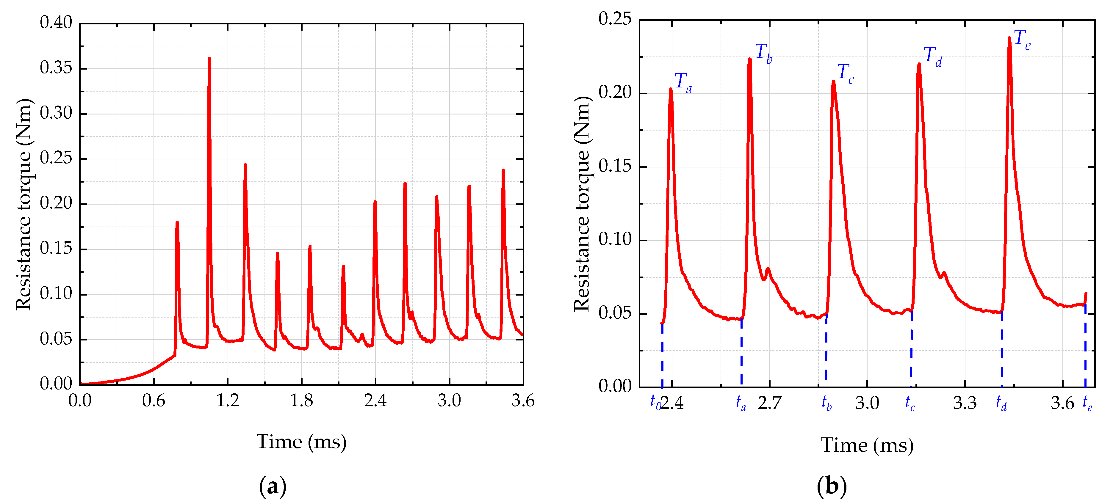
| Time Node | Value | Torque Peak | Value |
|---|---|---|---|
| ta | 2.612 ms | Ta | 5.765 T0 |
| tb | 2.872 ms | Tb | 6.346 T0 |
| tc | 3.136 ms | Tc | 5.920 T0 |
| td | 3.412 ms | Td | 6.256 T0 |
| te | 3.668 ms | Te | 6.734 T0 |
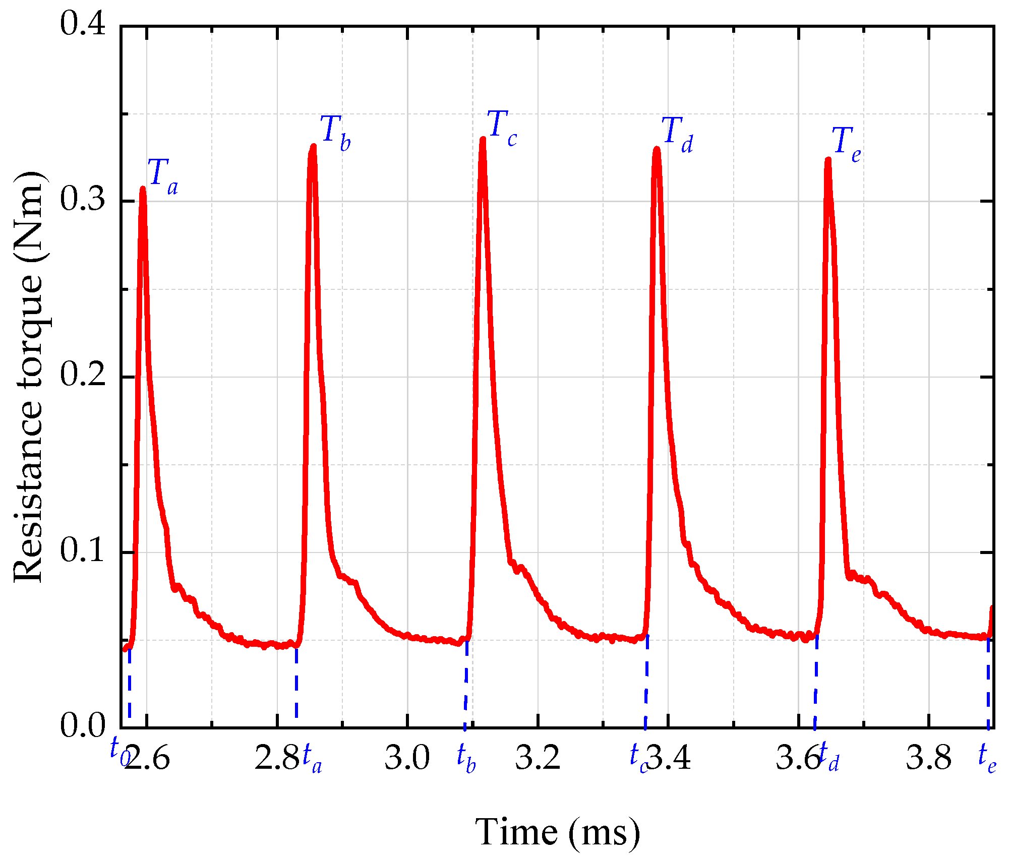
| Time Node | Value | Torque Peak | Value |
|---|---|---|---|
| ta | 2.832 ms | Ta | 6.986 T0 |
| tb | 3.092 ms | Tb | 7.538 T0 |
| tc | 3.362 ms | Tc | 7.631 T0 |
| td | 3.622 ms | Td | 7.503 T0 |
| te | 3.888 ms | Te | 7.365 T0 |
Publisher’s Note: MDPI stays neutral with regard to jurisdictional claims in published maps and institutional affiliations. |
© 2022 by the authors. Licensee MDPI, Basel, Switzerland. This article is an open access article distributed under the terms and conditions of the Creative Commons Attribution (CC BY) license (https://creativecommons.org/licenses/by/4.0/).
Share and Cite
Dai, Y.; Liang, C.; Chen, X.; Zhu, X. Numerical Analysis for Wetting Behaviors of an Oil Jet Lubricated Spur Gear. Lubricants 2022, 10, 17. https://doi.org/10.3390/lubricants10020017
Dai Y, Liang C, Chen X, Zhu X. Numerical Analysis for Wetting Behaviors of an Oil Jet Lubricated Spur Gear. Lubricants. 2022; 10(2):17. https://doi.org/10.3390/lubricants10020017
Chicago/Turabian StyleDai, Yu, Chongyu Liang, Xi Chen, and Xiang Zhu. 2022. "Numerical Analysis for Wetting Behaviors of an Oil Jet Lubricated Spur Gear" Lubricants 10, no. 2: 17. https://doi.org/10.3390/lubricants10020017
APA StyleDai, Y., Liang, C., Chen, X., & Zhu, X. (2022). Numerical Analysis for Wetting Behaviors of an Oil Jet Lubricated Spur Gear. Lubricants, 10(2), 17. https://doi.org/10.3390/lubricants10020017