Article

A New Approach for the Tribological and Mechanical Characterization of a Hip Prosthesis Trough a Numerical Model Based on Artificial Intelligence Algorithms and Humanoid Multibody Model

Department of Engineering, University of Messina, Contrada di Dio, 98166 Messina, Italy
*
Author to whom correspondence should be addressed.
Lubricants 2022, 10(7), 160; https://doi.org/10.3390/lubricants10070160
Submission received: 15 June 2022 / Revised: 7 July 2022 / Accepted: 12 July 2022 / Published: 18 July 2022
(This article belongs to the Special Issue Additive Manufacturing and Nano-Structured Surfaces in Tribology)

Abstract

:
In recent years, thanks to the development of additive manufacturing techniques, pros-thetic surgery has reached increasingly cutting-edge levels, revolutionizing the clinical course of patients suffering from joint arthritis, rheumatoid arthritis, post-traumatic arthrosis, etc. This work aims to evaluate the best materials for prosthetic surgery in hip implants from a tribological and mechanical point of view by using a machine-learning algorithm coupling with multi-body modeling and Finite Element Method (FEM) simulations. The innovative aspect is represented by the use of machine learning for the creation of a humanoid model in a multibody software environment that aimed to evaluate the load and rotation condition at the hip joint. After the boundary conditions have been defined, a Finite Element (FE) model of the hip implant has been created. The material properties and the information on the tribological behavior of the material couplings under investigation have been obtained from literature studies. The wear process has been investigated through the implementation of the Archard’s wear law in the FE model. The results of the FE simulation show that the best wear behavior has been obtained by CoCr alloy/UHMWPE coupling with a volume loss due to a wear of 0.004 μ m 3 at the end of the simulation of ten sitting cycles. After the best pairs in terms of wear has been established, a topology optimization of the whole hip implant structure has been performed. The results show that, after the optimization process, it was possible to reduce implant mass making the implant 28.12% more lightweight with respect to the original one.

1. Introduction

In recent years, thanks to the development of additive manufacturing techniques, prosthetic surgery has reached increasingly cutting-edge levels, revolutionizing the clinical course of patients suffering from joint arthritis, rheumatoid arthritis, post-traumatic arthrosis, congenital dysplasia, etc. In fact, the use of 3D printing has made it possible to obtain prostheses optimized [1] for the needs of patients by using high-performance materials such as stainless steel 316L [2] or Ti-6Al-4V [3,4]. However, due to the kinematics and dynamic nature of implants, wear is primarily caused by regular gait activity such as walking, sitting, or running, leading to the deterioration of the materials used in the joint [5,6]. The problems of friction and wear in hip prostheses, as well as in other types of mechanical joints, have been studied by many authors [7,8] to quantify the effects on the quality, reliability, and durability of the prostheses. Shankar et al. [9] investigated the tribological behavior of zirconia toughened alumina (ZTA) against titanium alloy (Ti-6Al-4V), using ball-on-disc tribometer with four loading conditions (15, 20, 25 and 30 N) and five different bio-lubricants to evaluate the friction and wear. Their obtained results suggested that sesame oil could improve tribological behavior as a bio-lubricant for ZTA-Ti-6Al-4V combination. Mattei et al. [10] performed a preliminary experimental investigation on the evolution of the wear map of hip replacements during wear testing for ceramic-on-UHMWPE hip prostheses. The results revealed important characteristics of the damaging process not highlighted by the standard gravimetric procedure, such as worn area location and shape as well as the progress of local damages. As demonstrated by numerous studies, the use of traditional materials has been gradually replaced using more performing materials [11,12,13]. The attention has been focused on the wear resistance, corrosion resistance, and biocompatibility, and the traditional techniques of production have been joined by the Additive Manufacturing (AM) technique. Through the AM, it was possible to obtain customized devices on the needs of patients and therefore more effective. Moreover, in order to guarantee a longer life cycle of the prostheses and an appropriate lubrication, the application of nanostructured coatings and surface processing was studied [14,15,16,17], such as the surface laser texturing technique already widely used in other industrial sectors [18,19]. Numerical techniques, such as the Finite Element Method (FEM), have recently been adopted to support experimental studies regarding the calculation of the useful life and the functionality optimization of the prostheses [20]. These techniques support the already developed algorithms based on the use of artificial intelligence and machine learning, which allow the determination of fundamental parameters, such as the position of the center of mass [21,22,23], and the evaluation of the exact load distribution on the prostheses. Fadela et al. [24] have analyzed the optimal stress distribution in the total hip prostheses with the aim to develop a redesigned prosthesis type in order to minimize stress concentration in the cement using 3D-finite element analysis. Bhawe et al. [25] have analyzed how the combination of UHMWPE, CoCrMo alloy, and Ti-6Al-4 V alloy affect the femoral head sizes from 24 mm to 48 mm to know the best size using the Finite Element Method (FEM). This work aims to evaluate the best materials for prosthetic surgery from a tribological and mechanical point of view by using a machine-learning [26] algorithm coupled with a multi-body model of a human body and Finite Element Method (FEM) simulations. The innovative aspect is represented by the use of machine learning, which allows the identification of the marker motion of a humanoid model developed in a multibody software environment. This approach could be an alternative strategy for the simulation of the load and rotation condition on a hip prosthesis concerning the conventional ones, such as hip simulators. The information on the tribological behavior of the materials is obtained through a Pin on Disk FEM model, which allows the optimization of the prosthesis, suggesting the best geometry and the highest-performing materials. In particular, the attention has been focused on hip prosthetic implants and on the wear process between the femoral head and the acetabular cup. A humanoid model has been developed in an MSC ADAMSTM environment aimed at evaluating the load and rotation conditions on the hip joint during sitting cycles. A FEM of a hip implant has been developed in Ansys workbench R2 2020TM environment in order to establish which of the following pairs have a better behavior in terms of volume loss due to wear:
  • CoCr Alloy/UHWMPE
  • Ti6Al4V/Ti6Al4V
  • Si3N4-TiN/Si3N4-TiN
The choice of investigating these couplings is related to the fact that they are biocompatible materials largely used in commercial hip implants [27]. Moreover, metal-metal couplings such as CoCrMo and Ti6AlV are well investigated in literature from the stress distribution point of view [28]. In this sense, this work represents an evolution because it gives additional information about the wear behavior, which completes the general overview for this materials type. Concerning the ceramic-ceramic coupling (Si3N4-TiN), it was already investigated by the authors [20], but in this work, it adopted a different prosthesis geometry, and the load and rotation conditions were evaluated by a customizable humanoid model and not from gait cycles coming from literature studies [29] like in the previous work. The wear process was investigated through the implementation of the Archard’s law [20,30,31,32] in the FEM and whose characteristic coefficients have been obtained from literature studies [6,20,33,34,35]. At the end of the simulations, it was observed that the best wear behavior was demonstrated by the CoCr alloy/UHMWPE coupling, with its volume loss due to wear being 0.004 μ m 3 at the end of the sitting cycles. The results have been also compared with the literature studied [5,6,9,10,20,29] and show a good agreement with them. After the best pairs in terms of wear were established, a topology optimization of the whole hip implant structure was performed. The results show that, after the optimization process, it was possible to reduce implant mass and minimize the compliance of the entire system, making the implant lightweight and more comfortable for the patients.

2. Materials and Methods

2.1. Numerical Modeling

The development of human models increased with the necessity to understand the biomechanics of movements and their consequences on human comfort [25,26,27,28]. These models are always used to simulate prosthetic design’s influence on the human system [29,30,31,32,33,34]. In recent years, particular importance has been given to modeling the jaw and its interactions with prostheses. The CT scan has characterized the bony structure. In the literature, various models allow the extrapolation of the mechanical characteristics, and the constraints and the loads on certain bodies subjected to specific actions [35,36,37,38,39,40,41,42,43,44]. Researchers are increasingly focusing on creating models that simulate the whole body rather than limiting themselves to small, specific sections [45]. Simulation techniques such as the multibody study the whole-body motion since the body is considered a set of links connected by joints. Multibody [46] simulations find a great application in sports biomechanics [47]. On this basis, the definition of the dynamic equation of human movement and the acquisition of the dynamic parameters of human action are the critical steps in the theoretical analysis of the biomechanics of movement. Another field of dynamic simulation is the analysis of the interaction between the human exoskeletons [48]. Finally, motion capture is often used to define the trajectories of body joints in multi-body simulations. With this technique, the movement of an object is recorded through various video acquisition devices arranged in space. From the recorded images, the coordinates (X, Y, Z) of a series of markers affixed to the subject are found; this allows one to quantify the position, speed, acceleration of these points and, consequently, the movement produced by the subject during a given action. This enables one to fully understand the mechanical characteristics underlying the human body’s activities and the rules for controlling motor skills. The workflow adopted in this study is shown in Figure 1.

2.2. Parametric Human Model

As reported previously, this work aims to make a closing loop simulation, where the output is the optimization of a hip prosthesis. The first step was the building of the human model. ADAMS was used to build the multi-body model, as reported in [49,50]. Thirty-one dimensions were used to create the mannequin (Table 1).
The human model was divided into:
  • Lower limbs: Left/Right Thigh, Left/Right Shank, Left/Right Foot.
  • Upper limbs: Left/Right Upper arm, Left/Right Forearm, Left/Right Hand.
  • Torso: Pelvis, Abdomen, Thorax.
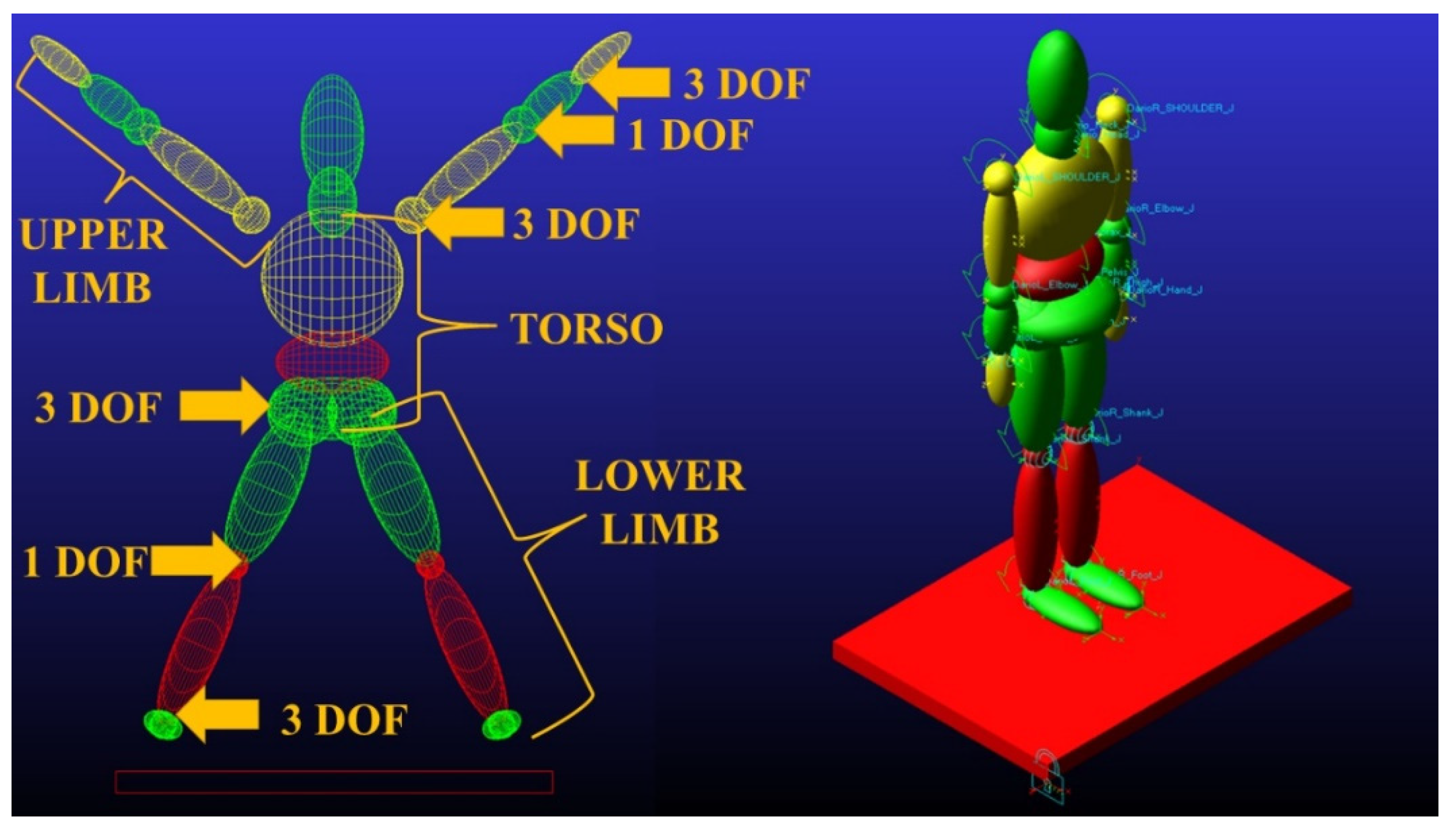
Each part was connected to another by a spherical joint. Each human segment has 3 DOF. Two knee and elbow joint rotations were locked (Figure 2). Contact with the ground and left and right feet were created.
The mannequin has the following characteristics:
  • Weight: 85 kg
  • Standing Height: 1755 mm
  • Seated Height: 918 mm
Inertial quantities and mass distribution were calculated as reported in [51,52]. Finally, motion lows were applied to the knee and hip joints to reproduce the stand-to-sit movement.

2.3. Motion Capture

Human pose estimation is the process of inferring human poses from a digital image. Pose estimation requires highly accurate detection and identification of human joints. Pose estimation algorithms follow a top-down or a bottom-up approach. As reported previously, after building the dummy, the motion lows were included in the model. For this reason, a markerless motion capture analysis was performed. OpenPose was used to evaluate realtime body pose [53,54,55,56]. OpenPose is a bottom-up, real-time, multi-person human pose detection library that detects the human body, foot, hand, and facial keypoints on single images. It can detect 135 vital body points from a digital image. The innovative tense is that no markers are needed. A single CNN is used for both key-point detection and association. When key points are detected, a numerical score between 0 and 1 is assigned. It is a measure of the overall confidence in the key points estimated. OpenPose has been trained to produce three different pose models. The difference is represented by the number of points identified:
  • MPI can estimate a total of 15 key points.
  • COCO can estimate a total of 18 points.
  • BODY_25 can estimate a total of 25 points.
The most exhaustive pose model is the third. In addition to the key points estimated by MPI and COCO models, it contains descriptors for the feet and pelvic center. There is also an experimental model of OpenPose that is named BODY_25B (Figure 3). As reported in [57,58], this model has the highest accuracy parameters, is more accurate than the default BODY_25, and reduces the number of false positives. The key point definition differs from MPII for the evaluation of head and neck key points and removes the neck and middle hip key points of the BODY_25 model. As shown in Figure 2, BODY_25B was used for the analysis.

2.4. Experimental Tests

2.4.1. Sit-to-Stand Movement

The sit-to-stand test (STS) involves movements done with great frequency in daily life. This test quantifies the type of movement to get up from a chair [59] and the loads acting on the locomotor system [60]. STS involves skills such as coordination, balance control, and stability [61,62]. The number of repetitions completed provides quantitative information with which to assess functional fitness levels [63], and the test was used in the rehabilitation field. Recently, several studies have highlighted the importance of kinematic parameters to provide qualitative information on how the movement is performed. This movement can be schematized as acting on the plane; for this reason, it is helpful for the calibration of the optimization algorithm.

2.4.2. Motion Acquisition and Multibody Analysis

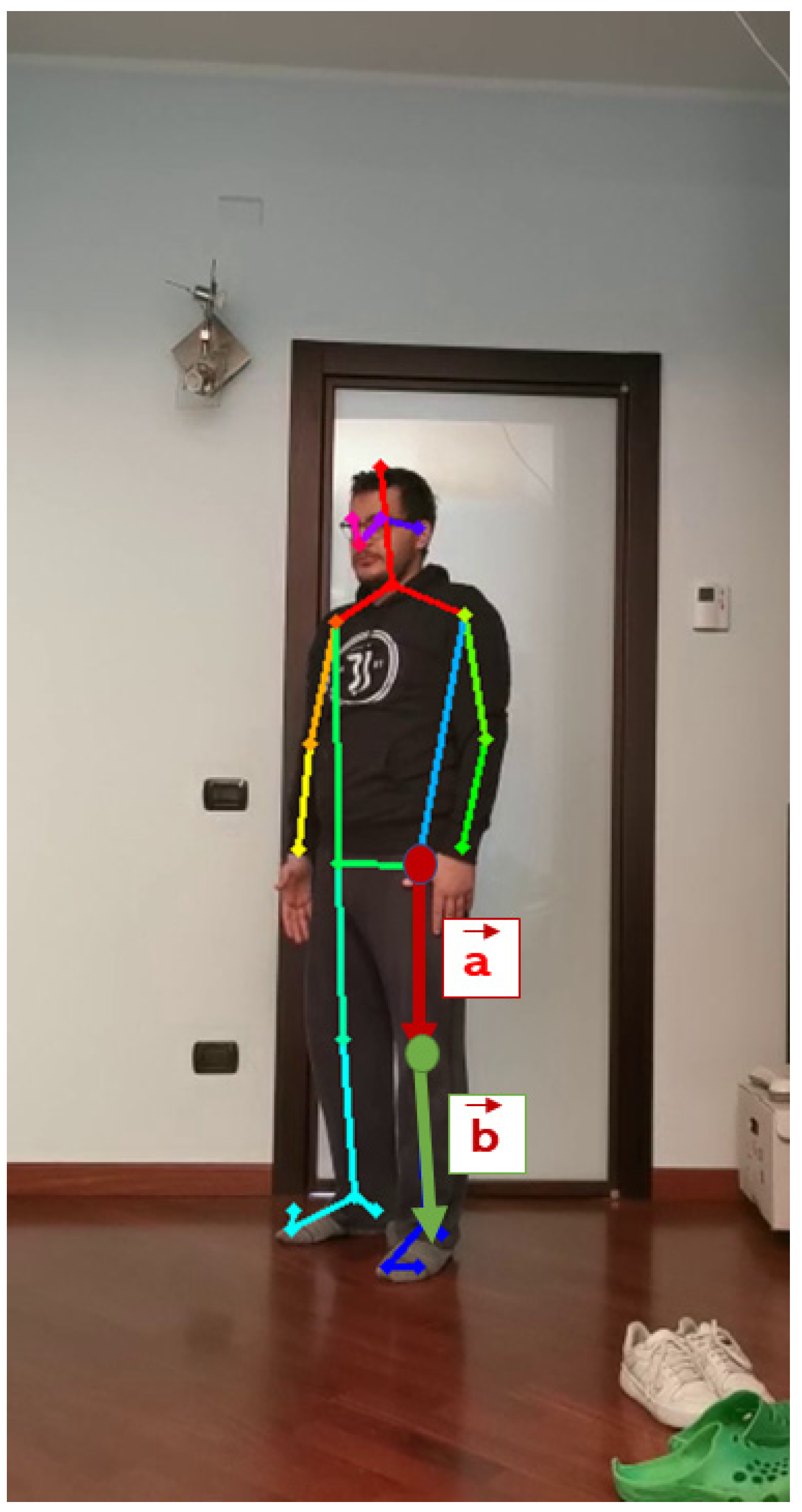
The subject was positioned in front of the camera in a standing position. The angle between hip/spine and knee/hip is 180 degrees in this situation. A video of its movement was recorded. The subject performed the sit-to-stand exercise sequentially. The handling of the points was extrapolated with the use of OpenPose. As in [64], the knee angle was calculated using the vector dot product.
θ = cos 1 ( a b | a | | b | )
Two vectors were constructed from the hip, knee, and ankle coordinates obtained from the pose data. The first vector was formed with the hip and knee joint, while the knee and ankle joint formed the second one. The same things were done to evaluate hip angle. The following equation gives the knee angle ( θ ) for the frame in Figure 4.
Two vectors were constructed from the hip, knee, and ankle coordinates obtained from the pose data. The first vector was formed with the hip and knee joint, while the knee and ankle joint formed the second one. After the extrapolation of the angles from the frames, the laws of motion were created in ADAMS (Figure 5).
The movement of the humanoid was simulated; therefore, the loads acting on the hip were extrapolated over time.

2.5. Hip Prosthesis Finite Element Model (FEM)

2.5.1. Geometry, Mesh, and Boundary Condition Definition

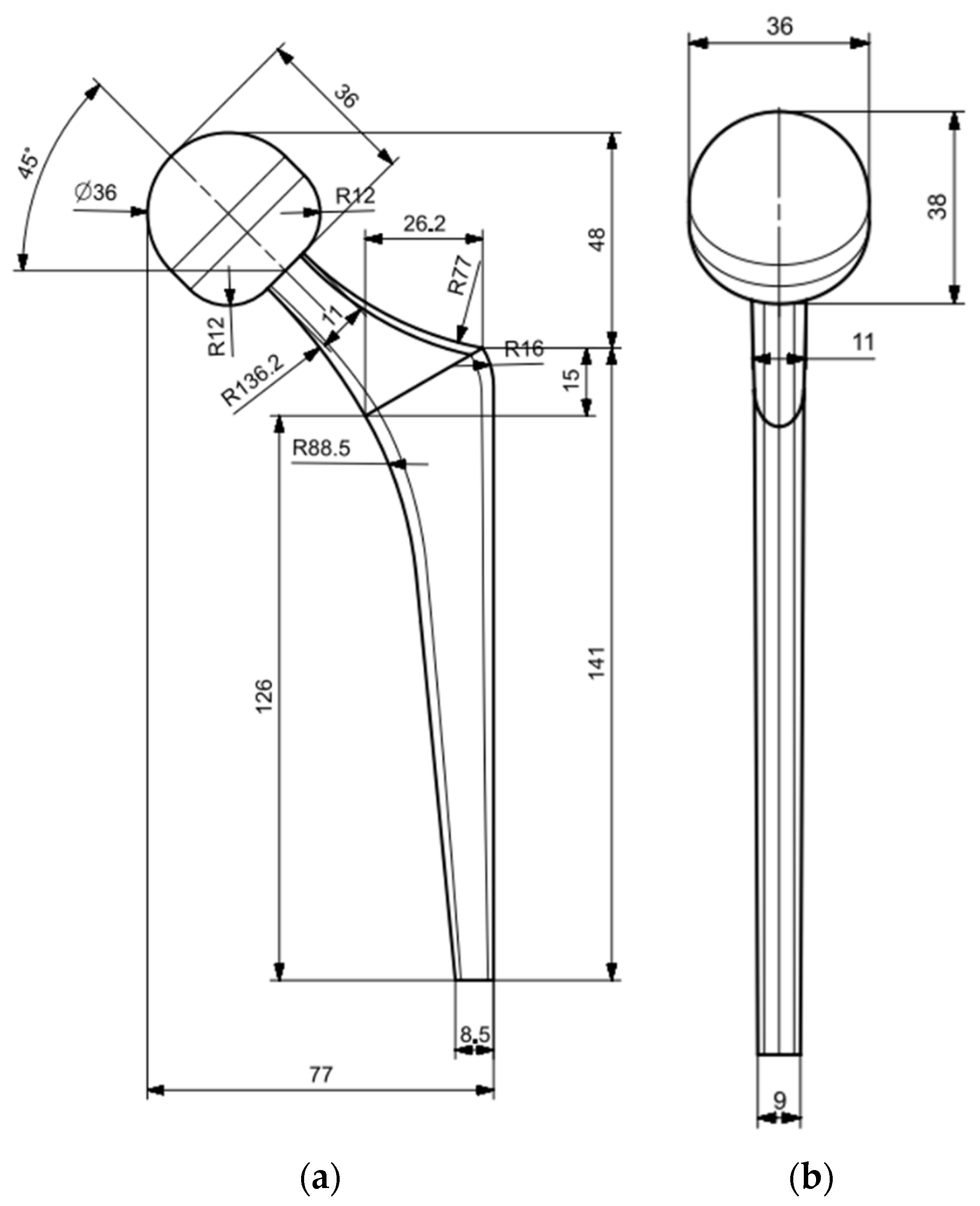
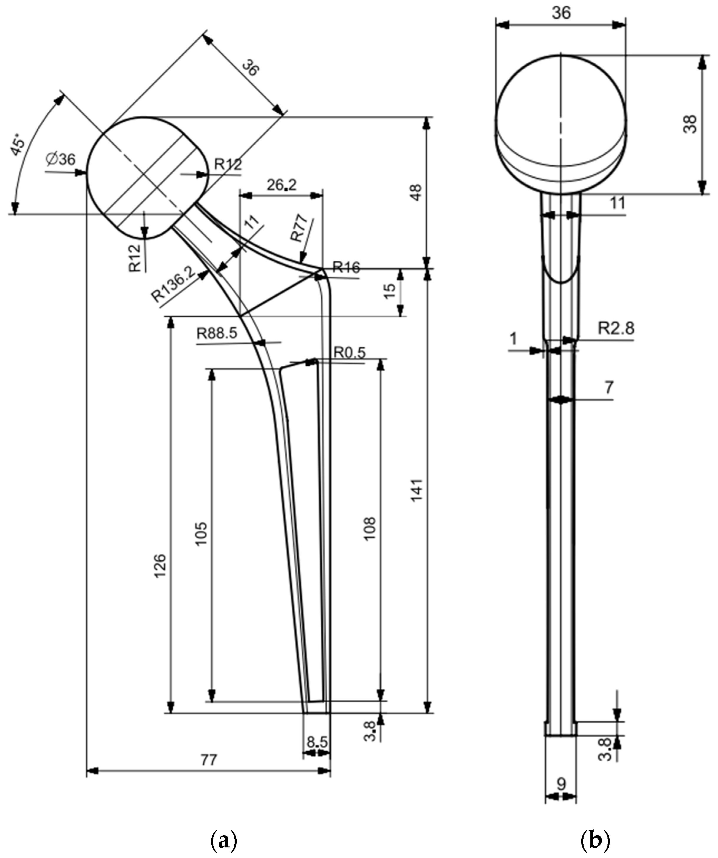
The prosthesis implant adopted in this work for the Finite Element Analysis (FEA) is a commercial hip implant. The main geometry parameters are shown in Figure 6.
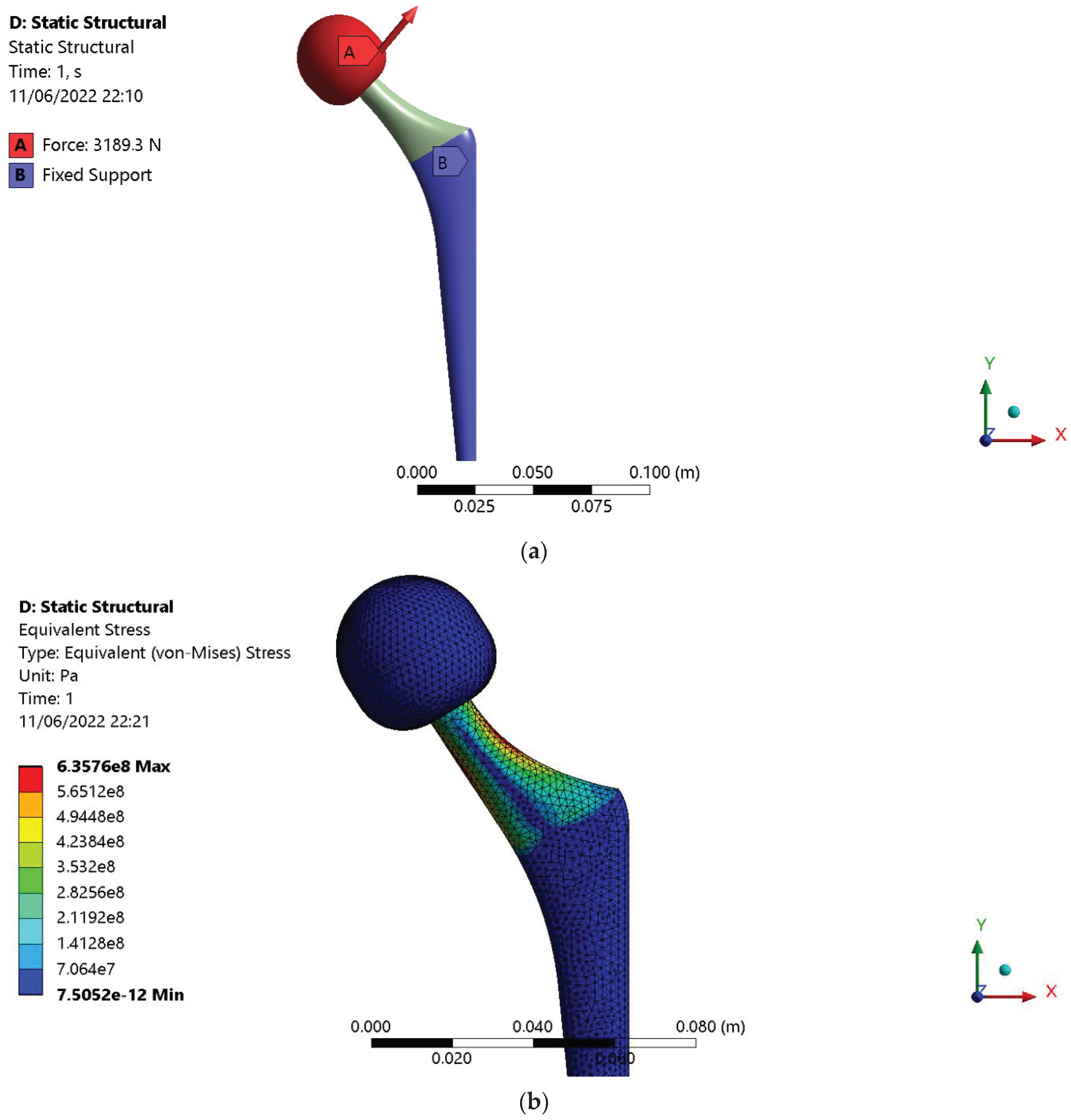
The FEM has been developed in Ansys workbench R2 2020TM environment. In order to establish the optimal mesh size, a convergence analysis was performed first. This was done because the optimal mesh size allows to obtain accurate results without exceeding too much with the simulation time. The convergence analysis has been carried out through a static simulation on the hip implant, choosing the maximum load components during a sitting cycle, evaluated from the human multibody model developed in MSC ADAMSTM. The boundary condition adopted in the Finite Element Model consists of a fixed support applied to the prosthesis stem. The load condition has been applied to the femoral head and modeled as surface effect. Figure 7a shows the load and constrain conditions, while Figure 7b shows the equivalent stress (Von Mises criterion) after the static simulation.
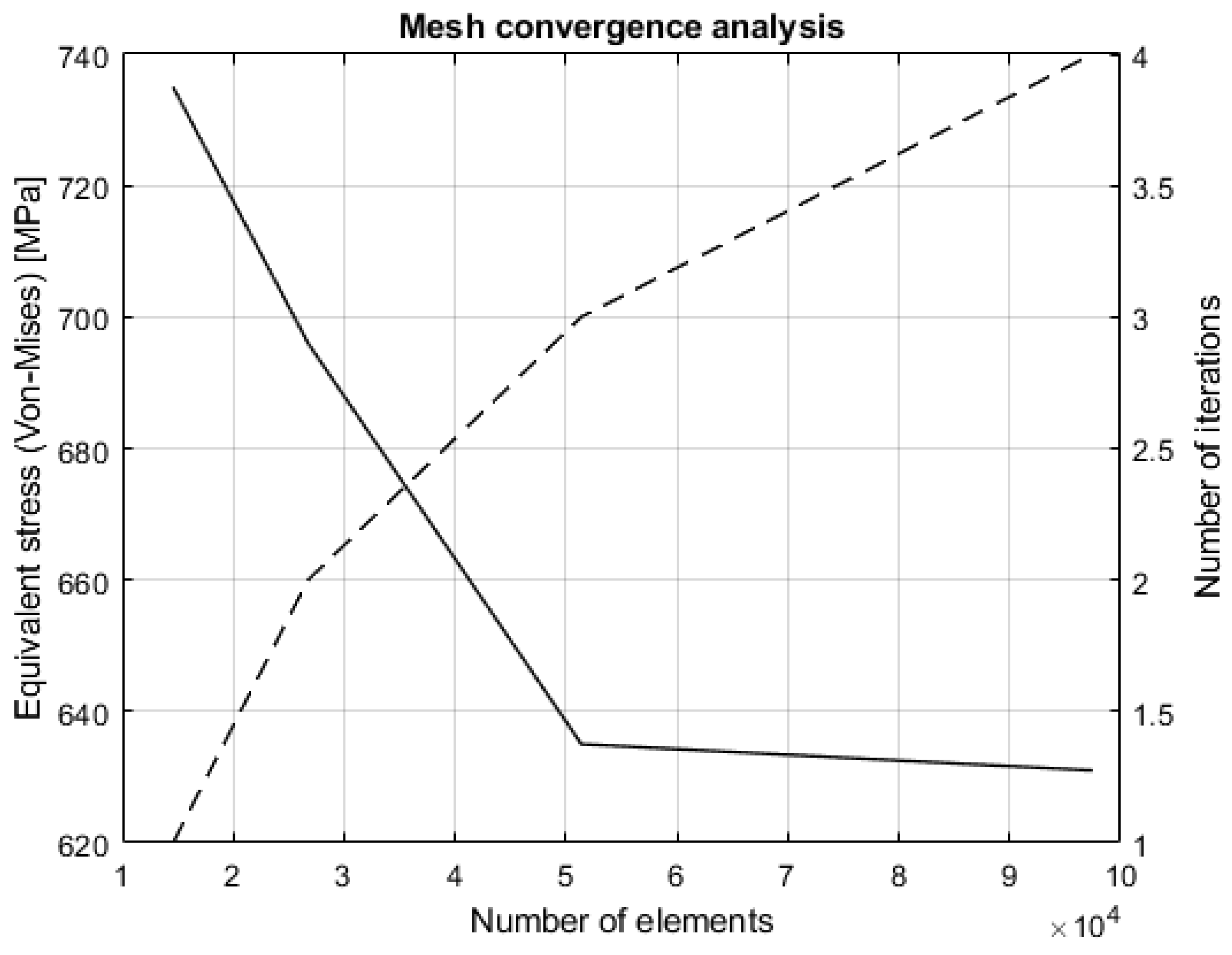
Starting from a coarser mesh, the convergence was obtained by increasing the number of element and at the same time reducing the element size. The results of the convergence analysis are shown in Figure 8 and Table 2, respectively.
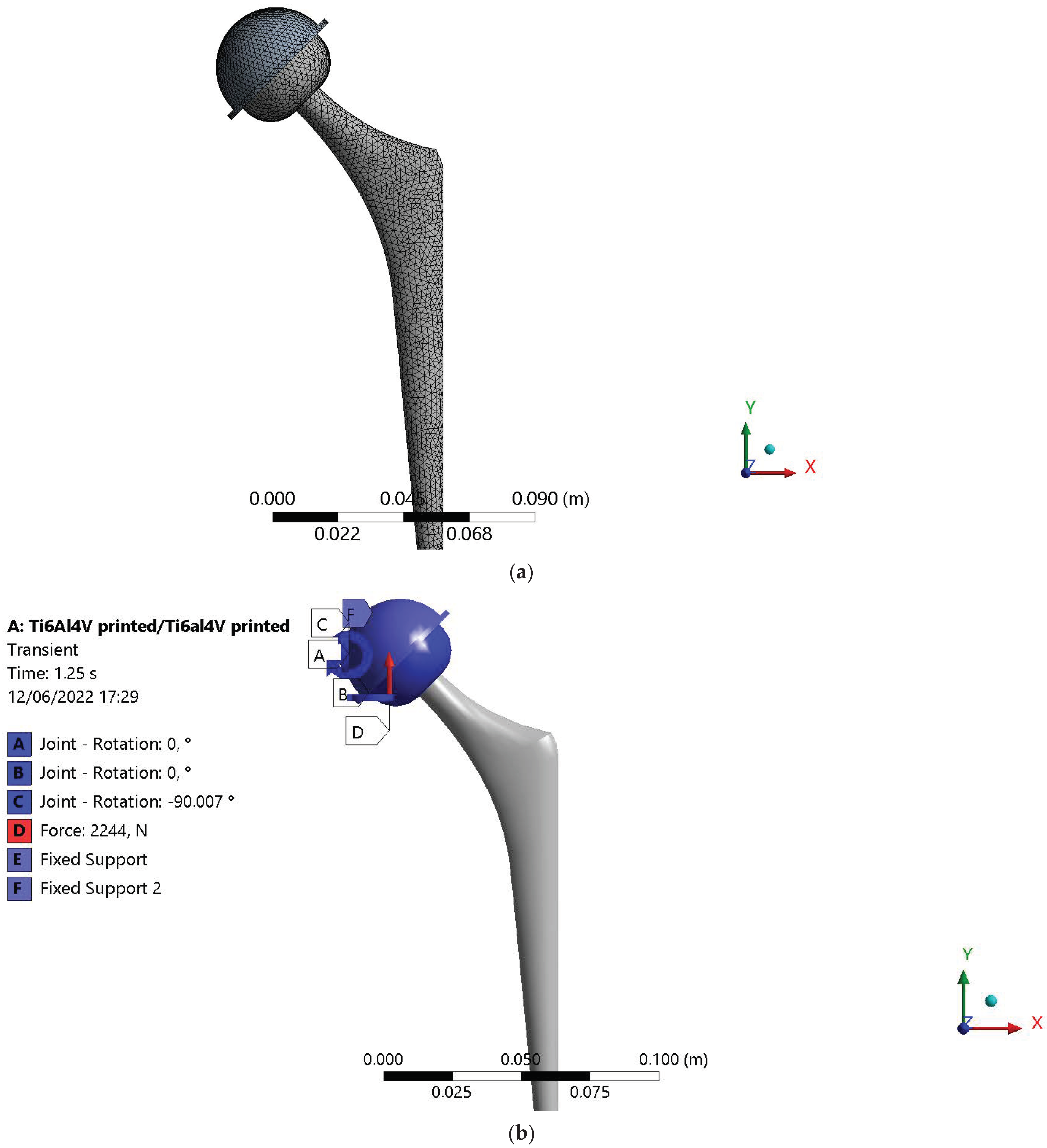
The selected mesh size for the simulations is 2 mm with 51,379 elements and was reached at the third iteration. In order to investigate the wear process between the acetabular cup and the femoral head and simulate the sitting cycles, a transient analysis was carried out. In addition to the mesh size already being defined, load, rotation and constrain condition were considered into the model. A fixed support has been applied to the external and internal surface of the acetabular cup. The load condition was applied to the femoral head and modeled as surface effect. This means that the forces were applied to the selecting surface area through the definition of several nodes controlled by the software itself. Of course, the sum of the nodal forces is equal to the imposed transient force. This method is useful when rotations and area changes are expected during the simulation, like in this case. The mesh adopted in the simulation is shown in Figure 9a, while the boundary conditions are shown in Figure 9b.
The mesh element type used in the FEM is a Tetra 3D element which consist of a high order 20-node SOLID186 element. The element is defined by 20 nodes having three degrees of freedom per node, i.e., translation in the nodal x, y, and z directions. The element also supports plasticity, large strain, and large deflection. The solid mesh has been generated using “Automatic Method” workbench command. A frictional contact type has been implemented in the simulation, considering the acetabular cup as target surface, modeled with TARGE170 element, and the femoral head as the contact surface, modeled with CONTA174 element.

2.5.2. Archard’s Wear Law Implementation

In order to thoroughly investigate the wear process between the acetabular cup and the femoral head, it is necessary to implement a wear model in the FEM. In this study, the Archard’s law, defined in Equation (2), was implemented in the transient simulation:
w = K H p m v n
where w is the wear rate, K is the Archard’s wear coefficient, H is the material hardness, p is the contact stress, and v is the sliding velocity. The Archard’s law described above makes no assumption about surface topography since the surface roughness effects are encompassed by the experimental wear coefficient K , which is usually calibrated through Pin On Disk experimental tests. In addition, it also makes no assumption about variations with time. Although it is widely used, the Archard’s law only provides an order of magnitude estimates and is a true calculation of wear. Despite this, the Archard’s law provides accurate information about the wear behavior of a material coupling, especially when the law is calibrated based on experimental tests [20]. Three different pairs have been compared in this work:
  • CoCr Alloy (femoral head)/UHWMPE (acetabular cup)
  • Ti6Al4V (femoral head)/Ti6Al4V (acetabular cup)
  • Si3N4-TiN (femoral head)/Si3N4-TiN (acetabular cup)
The materials pairs parameters [6,20,28,29,33,34,35,65] related to Equation (2) are shown in Table 3.
The value of the friction coefficient, which is usually evaluated from experimental tests using a tribometer with Pin On Disk configuration, changes during the tribological test. This happens because the lubricant film adopted during the test, which simulate the synovial fluid, gets thinner away, increasing the value of the friction coefficient. Therefore, the final value assumed by the friction coefficient and adopted in the FEM, corresponds to that obtained in dry condition, neglecting the influence of the synovial fluid. This assumption is also in agreement with scientific studies [20,28].

2.5.3. Topology Optimization

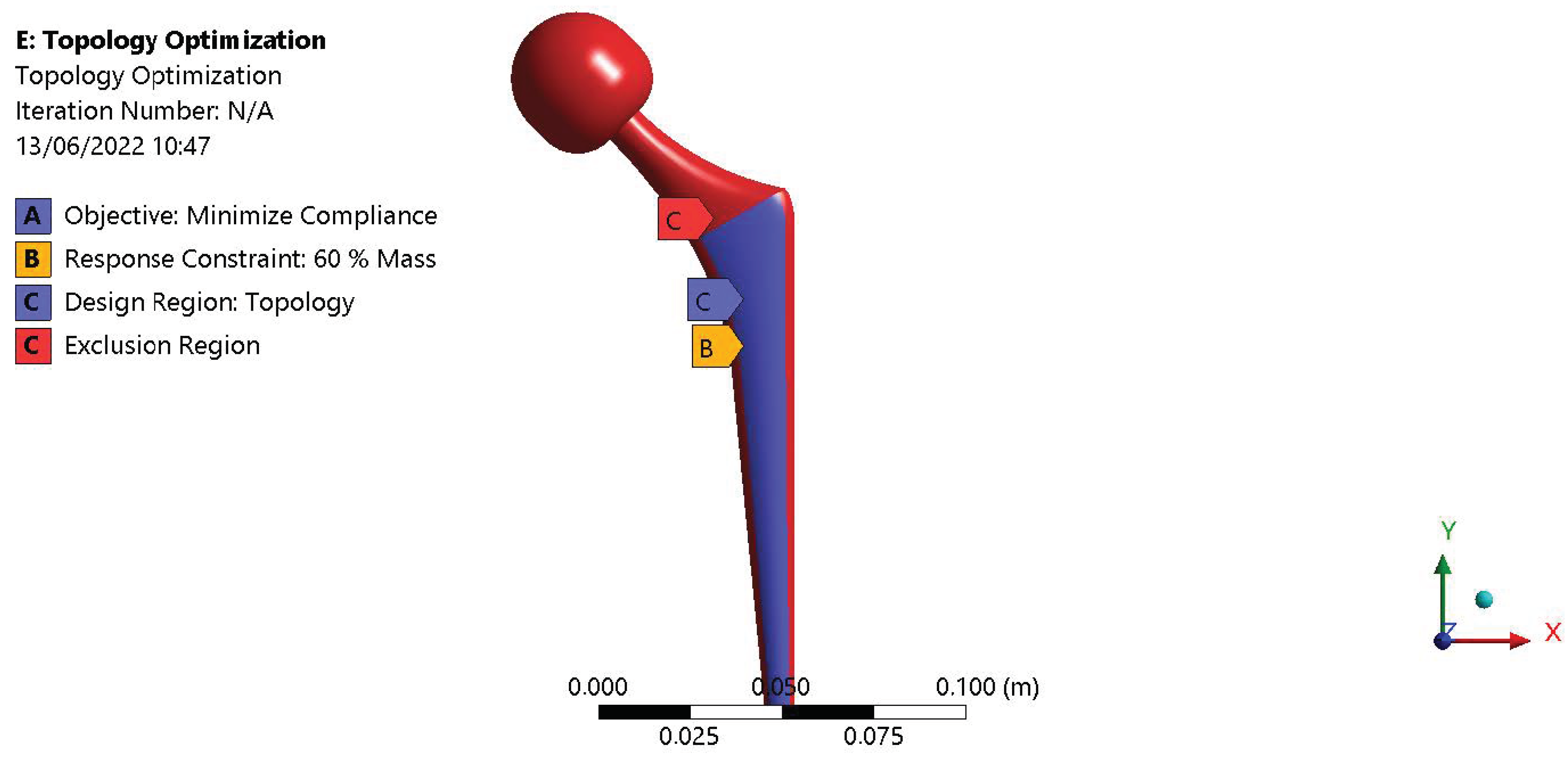
After establishing the best materials pairs in terms of volume loss due to wear, a topology optimization was performed through a static structural simulation, considering the maximum load components applied to the femoral head. This was carried out in order to reduce the prosthetic implant mass and at the same time minimize the implant compliance. Considering the boundary condition in Figure 7a and, as consequence, the stress distribution shown in Figure 7b, the attention has been focused on the implant stem, since this region is not affected by particularly high stress. Figure 10 shows the decision region used for the topology optimization.

3. Results

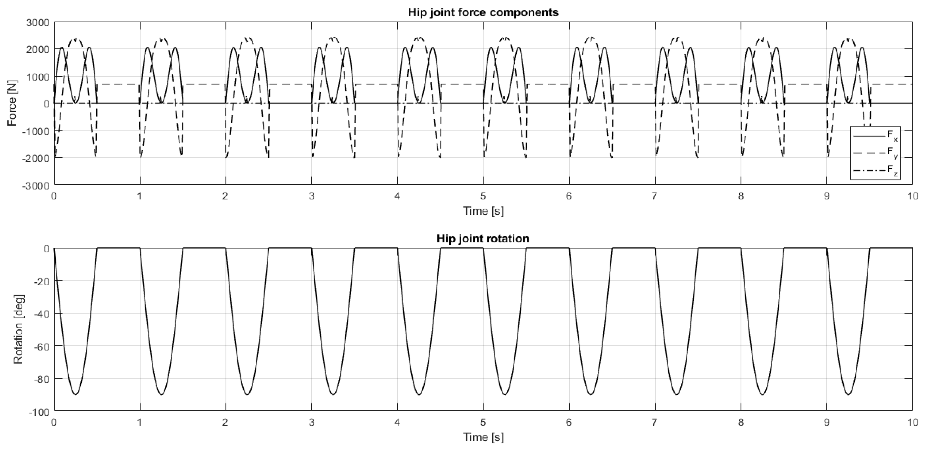
The combined action of Artificial Intelligence and machine learning, together with a human model developed on a multibody environment, allowed for the evaluation of the load and rotation conditions at the hip joint. In particular, ten sitting cycles were considered for a simulation time of 10 s. Figure 11 shows the load and the rotation conditions at the thigh joint, evaluated from the multibody model.
The load and rotation conditions evaluated from the multibody model of a human body represents the boundary condition for the study of the wear process between the femoral head and the acetabular cup, which was evaluated through a FEM. In particular, the attention was focused on the volume loss due to wear of the femoral head, of which the behavior was modeled through Archard’s law. Figure 12 and Table 4, respectively, show the comparison of the volume loss due to wear (related to the acetabular cup) for three different materials used in the prosthetic biomedical field.
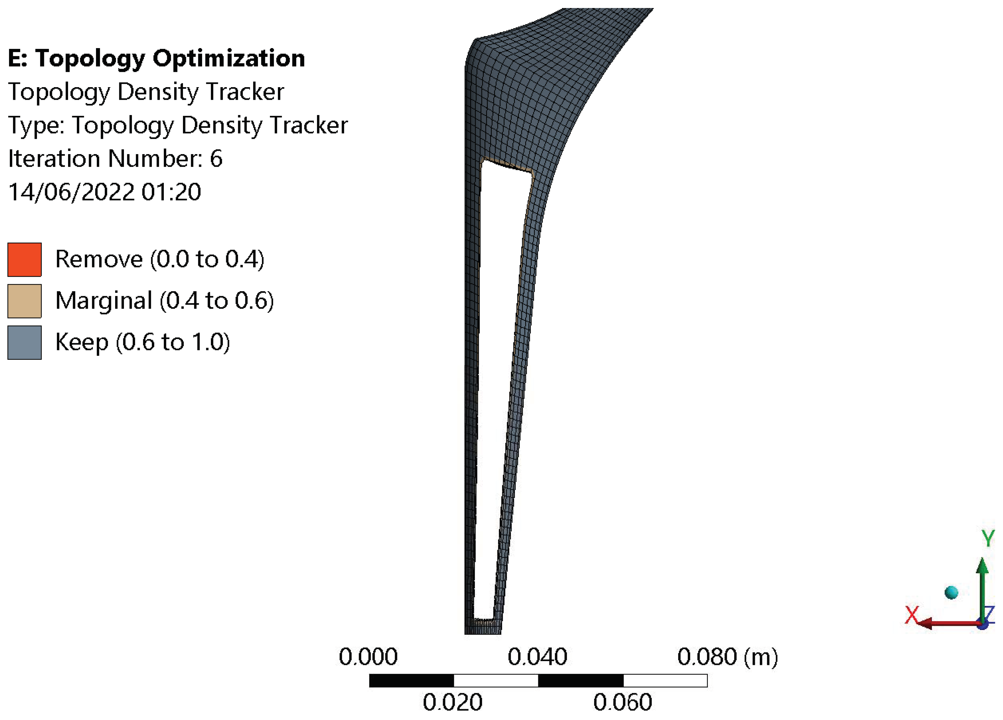
According to the results exposed in Figure 12 and Table 4, respectively, the best materials pair is CoCr alloy/UHMWPE because it presents the lowest value of volume loss due to wear at the end of the sitting cycle. For this material pair, we also performed a topology optimization in order to minimize the compliance and at the same time reduce the prosthesis mass. Figure 13 shows the results of the topology optimization.
Figure 14 shows the comparison between the original prosthesis design and the optimized one.
The comparison between the original prosthesis mass and the optimized one is shown in Table 5.

4. Discussion

The results shown in Figure 3 and Figure 4, respectively, demonstrate that the implementation of an AI algorithm and the use of OpenPose software allows the identification of the main marker of a real human subject, including the hip joint position. Therefore, the multibody model of a human body developed in MSC ADAMS TM has been validated based on a real human subject. Moreover, the multibody model is fully parametric and hence it is possible to select a specific quartile depending on weight and height of the human subject. In particular, the selected quartile adopted for the simulation is a male subject with a weight of 85 kg and a height of 1.75 m. Figure 10 shows that from the multibody model of a human body, it was possible to evaluate the load and rotation conditions at the hip joint during ten sitting cycles. Figure 11 shows the sitting cycles that occurred in 10 s simulation times. The sitting cycles are composed of a dynamic part related to the joint movement and a static part related to the contribution of the human body mass, when it remains stationary. In addition, the joint rotation is a planar movement and, as consequence, has only the component perpendicular to the x-axis, from 0 to 90 degrees. From the FEM of a hip prosthesis developed in Ansys Workbench R2 2020TM, it was possible to compare three different materials pairs used in biomedical fields in terms of wear between the acetabular cup and the femoral head: CoCr Alloy/UHMWPE, Ti6Al4/Ti6Al4, Si3N4 -TiN/Si3N4 -TiN. The wear process has been studied trough the implementation of the Archard’s wear law in the FEM. The materials’ properties have been obtained by previous literature studies, and the influence of the synovial fluid related to the coefficient of friction has been neglected. The results shown in Figure 12 and Table 4, respectively, demonstrate that the better behavior in terms of volume loss due to wear (related to the femoral head) was achieved by CoCr alloy/UHMWPE pairs, with a value of 0.004 μ m 3 at the end of the sitting cycle. The obtained results are also in agreement with literature studies [5,6,9,10,20,29]. Investigating the trend of the volume loss due to wear shown in Figure 12, it is possible to assess that it is inherent with the imposed sitting cycle. In fact, during the movement of the hip joint, the volume loss due to wear increased, while it remained stationary during the stationary phase of the sitting cycle. Moreover, the increasing wear followed a linear trend, which was in agreement with the linear model (m and n equal to 1) adopted for the Archard’s law, defined in Equation (2). After establishing the best materials pairs in terms of volume loss due to wear, a topology optimization of the implant structure was performed. The attention for the topology optimization was focused on the implant stem, since this part is not directly involved in the action of the applied load, but it is fixed to the bone. Its main contribution is related to the global implant stiffness. As shown in Figure 13, the optimization algorithm is able to remove material in the decision region, with the aim of minimizing the implant compliance (and hence maximizing the implant stiffness) and at the same time reducing the prosthesis mass. At the end of the optimization process, the new prosthesis design was 28.12% more lightweight than the original one, as shown in Table 5.

5. Conclusions

The aim of this work was to perform a tribological characterization of three different materials pairs used in biomedical field, with the combined action of Machine Learning, multibody modeling, and Finite Element Analysis. The results show that the markerless approach represents an easy way to evaluate human motion without a sophisticated architecture. In particular, OpenPose is a machine learning algorithm that predicts joint rotations well. A multibody model of a human body was developed in an MSC ADAMSTM environment, and it was able to evaluate the load conditions at the hip joint during sitting cycles, together with the rotation condition evaluated from OpenPose. The human body model developed in multibody environment is fully parametric, and in this study, a male subject with a weight of 85 kg and a height of 1.70 m was investigated. Through a FEM of a hip prosthesis developed in Ansys Workbench R2 2020TM, it was possible to investigate the wear process between the femoral head and the acetabular cup through the implementation of the Archard’s wear law. The comparison between three materials types largely used in the biomedical field showed that the best behavior in terms of volume loss due to wear was achieved by CoCr alloy/UHMWPE pairs, with a final volume loss due to wear of 0.004   μ m 3 after ten sitting cycles. All the results have been compared with literature studies, showing a good agreement with them. At the end, considering the best material coupling, a topology optimization of the whole prosthesis structure was performed. The decision region was focused on the implant stem since this region is not characterized by particularly high stress. The results show that it was possible to reduce the implant mass by 28.12%. At the end, it is possible to assert that the humanoid model developed in multibody environment could represent a valid alternative for the estimation of the load and rotation conditions acting on a hip implant, with respect to conventional ones, such as hip simulators. The future development regards the implementation of more complex movement, such as gait cycles, the calibration of the multibody model on a real clinical case, the calibration of the Archard’s law with tribological experimental tests, avoiding the use of a linear wear model, and the study of the influence of coatings applied to femoral head and acetabular cup that aim to improve the wear behavior.

Author Contributions

D.M.: Conceptualization, methodology, software, validation, supervision, investigation, writing—original draft preparation, writing—review and editing. G.R.: Conceptualization, methodology, validation, supervision. A.P.: Conceptualization, methodology, validation, supervision. D.C.: Conceptualization, methodology, software, validation, supervision, investigation, writing—original draft preparation, writing—review and editing. F.A.: Conceptualization, methodology, software, validation, supervision, investigation, writing—original draft preparation, writing—review and editing. All authors have read and agreed to the published version of the manuscript.

Funding

This research received no external funding.

Institutional Review Board Statement

Not applicable.

Informed Consent Statement

Not applicable.

Data Availability Statement

Not applicable.

Conflicts of Interest

The authors declare no conflict of interest.

References

  1. Cucinotta, F.; Guglielmino, E.; Longo, G.; Risitano, G.; Santonocito, D.; Sfravara, F. Topology Optimization Additive Manufacturing-Oriented for a Biomedical Application; Springer International Publishing: Berlin/Heidelberg, Germany, 2019; Volume 1, ISBN 9783030123468. [Google Scholar]
  2. D’Andrea, D.; Risitano, G.; Guglielmino, E.; Piperopoulos, E.; Santonocito, D. Correlation between Mechanical Behaviour and Microstructural Features of AISI 316L Produced by SLM. Procedia Struct. Integr. 2022, 41, 199–207. [Google Scholar] [CrossRef]
  3. Epasto, G.; Palomba, G.; D’Andrea, D.; Guglielmino, E.; Di Bella, S.; Traina, F. Ti-6Al-4V ELI Microlattice Structures Manufactured by Electron Beam Melting: Effect of Unit Cell Dimensions and Morphology on Mechanical Behaviour. Mater. Sci. Eng. A 2019, 753, 31–41. [Google Scholar] [CrossRef]
  4. Epasto, G.; Palomba, G.; Andrea, D.D.; Di Bella, S.; Mineo, R.; Guglielmino, E.; Traina, F. Experimental Investigation of Rhombic Dodecahedron Micro-Lattice Structures Manufactured by Electron Beam Melting. Mater. Today Proc. 2019, 7, 578–585. [Google Scholar] [CrossRef]
  5. Fellah, M.; Labaiz, M.; Assala, O.; Dekhil, L.; Iost, A. Tribological Behavior of Biomaterials for Total Hip Prosthesis. Trends Biomater. Artif. Organs 2015, 29, 22–30. [Google Scholar] [CrossRef] [Green Version]
  6. Banchet, V.; Fridrici, V.; Abry, J.C.; Kapsa, P. Wear and Friction Characterization of Materials for Hip Prosthesis. Wear 2007, 263, 1066–1071. [Google Scholar] [CrossRef]
  7. Unsworth, A.; Hall, R.M.; Burgess, I.C.; Wroblewski, B.M.; Streicher, R.M.; Semlitsch, M. Frictional Resistance of New and Explanted Artificial Hip Joints. Wear 1995, 2, 226–231. [Google Scholar] [CrossRef]
  8. Saikko, V.O. A Three-Axis Hip Joint Simulator for Wear and Friction Studies on Total Hip Prostheses. Proc. Inst. Mech. Eng. Part H J. Eng. Med. 1996, 210, 175–185. [Google Scholar] [CrossRef]
  9. Shankar, S.; Nithyaprakash, R.; Abbas, G.; Naveen Kumar, R.; Pramanik, A.; Kumar Basak, A.; Prakash, C. Tribological Behavior of Zirconia-Toughened Alumina (ZTA) against Ti6Al4V under Different Bio-Lubricants in Hip Prosthesis Using Experimental and Finite Element Concepts. Mater. Lett. 2022, 307, 131107. [Google Scholar] [CrossRef]
  10. Mattei, L.; Di, F.; Ciulli, E.; Pauschitz, A. Tribology International Experimental Investigation on Wear Map Evolution of Ceramic-on-UHMWPE Hip Prosthesis. Tribol. Int. 2020, 143, 106068. [Google Scholar] [CrossRef]
  11. Kourra, N.; Warnett, J.M.; Attridge, A.; Dibling, G.; McLoughlin, J.; Muirhead-Allwood, S.; King, R.; Williams, M.A. Computed Tomography Metrological Examination of Additive Manufactured Acetabular Hip Prosthesis Cups. Addit. Manuf. 2018, 22, 146–152. [Google Scholar] [CrossRef]
  12. Murr, L.E. Additive Manufacturing of Biomedical Devices: An Overview. Mater. Technol. 2018, 33, 57–70. [Google Scholar] [CrossRef]
  13. Cortis, G.; Mileti, I.; Nalli, F.; Palermo, E.; Cortese, L. Additive Manufacturing Structural Redesign of Hip Prostheses for Stress-Shielding Reduction and Improved Functionality and Safety. Mech. Mater. 2022, 165, 104173. [Google Scholar] [CrossRef]
  14. Kashyap, V.; Ramkumar, P. Comprehensive Analysis of Geometrical Parameters of Crosshatched Texture for Enhanced Tribological Performance under Biological Environment. Proc. Inst. Mech. Eng. Part J. J. Eng. Tribol. 2021, 235, 434–452. [Google Scholar] [CrossRef]
  15. Allen, Q.; Raeymaekers, B. The Effect of Texture Floor Profile on the Lubricant Film Thickness in a Textured Hard-on-Soft Bearing with Relevance to Prosthetic Hip Implants. J. Tribol. 2021, 143, 021801. [Google Scholar] [CrossRef] [PubMed]
  16. Kashyap, V.; Ramkumar, P. DLC Coating over Pre-Oxidized and Textured Ti6Al4V for Superior Adhesion and Tribo-Performance of Hip Implant. Surf. Coat. Technol. 2022, 440, 128492. [Google Scholar] [CrossRef]
  17. Prince, R.M.R.; Selvakumar, N.; Arulkirubakaran, D.; Singh, S.C.E.; Das, M.C.; Bannaravuri, P.K.; Prabha, R.M.R.; Raj, J.A.; Robert, R.B.J. ZrC-Impregnated Titanium-Based Coating as an Effective Lubricating Barrier for Artificial Hip Prosthesis. Mater. Perform. Charact. 2021, 10, 189–205. [Google Scholar] [CrossRef]
  18. Senatore, A.; Risitano, G.; Scappaticci, L.; D’andrea, D. Investigation of the Tribological Properties of Different Textured Lead Bronze Coatings under Severe Load Conditions. Lubricants 2021, 9, 34. [Google Scholar] [CrossRef]
  19. Khaskhoussi, A.; Risitano, G.; Calabrese, L.; D’Andrea, D. Investigation of the Wettability Properties of Different Textured Lead/Lead-Free Bronze Coatings. Lubricants 2022, 10, 82. [Google Scholar] [CrossRef]
  20. D’Andrea, D.; Pistone, A.; Risitano, G.; Santonocito, D.; Scappaticci, L.; Alberti, F. Tribological Characterization of a Hip Prosthesis in Si3N4-TiN Ceramic Composite Made with Electrical Discharge Machining (EDM). Procedia Struct. Integr. 2021, 33, 469–481. [Google Scholar] [CrossRef]
  21. Ploof, G.; Alqahtani, B.; Alghamdi, F.; Flynn, G.; Yang, C.X. Center of Mass Estimation Using Motion Capture System. In Proceedings of the 2017 IEEE 15th Intl Conf on Dependable, Autonomic and Secure Computing, 15th Intl Conf on Pervasive Intelligence and Computing, 3rd Intl Conf on Big Data Intelligence and Computing and Cyber Science and Technology Congress (DASC/PiCom/DataCom/CyberSciTech), Orlando, FL, USA, 6–10 November 2017; pp. 287–292. [Google Scholar] [CrossRef]
  22. D’andrea, D.; Cucinotta, F.; Farroni, F.; Risitano, G.; Santonocito, D.; Scappaticci, L. Development of Machine Learning Algorithms for the Determination of the Centre of Mass. Symmetry 2021, 13, 401. [Google Scholar] [CrossRef]
  23. Tanaka, R.; Takimoto, H.; Yamasaki, T.; Higashi, A. Validity of Time Series Kinematical Data as Measured by a Markerless Motion Capture System on a Flatland for Gait Assessment. J. Biomech. 2018, 71, 281–285. [Google Scholar] [CrossRef] [PubMed]
  24. Fadela, A.; Habib, L.; Abderrahmane, B. Finite Element Analysis of Stress State in the Cement of Total Hip Prosthesis with Elastomeric Stress Barrier. Frat. Integrità Strutt. 2021, 15, 281–290. [Google Scholar] [CrossRef]
  25. Bhawe, A.K.; Shah, K.M.; Somani, S.; Shenoy, B.S.; Bhat, N.S.; Zuber, M.; KN, C. Static Structural Analysis of the Effect of Change in Femoral Head Sizes Used in Total Hip Arthroplasty Using Finite Element Method. Cogent Eng. 2022, 9, 2027080. [Google Scholar] [CrossRef]
  26. D’Andrea, D.; Risitano, G.; Desiderio, E.; Quintarelli, A.; Milone, D.; Alberti, F. Artificial Neural Network Prediction of the Optimal Setup Parameters of a Seven Degrees of Freedom Mathematical Model of a Race Car: IndyCar Case Study. Vehicles 2021, 3, 300–329. [Google Scholar] [CrossRef]
  27. Mahyudin, F.; Hermawan, H. Biomaterials and Medical Devices. Adv. Struct. Mater. 2016, 58, 207–234. [Google Scholar] [CrossRef]
  28. Ammarullah, M.I.; Afif, I.Y.; Maula, M.I.; Winarni, T.I.; Tauviqirrahman, M.; Akbar, I.; Basri, H.; van der Heide, E.; Jamari, J. Tresca Stress Simulation of Metal-on-Metal Total Hip Arthroplasty during Normal Walking Activity. Materials 2021, 14, 7554. [Google Scholar] [CrossRef]
  29. Uddin, M.S.; Zhang, L.C. Predicting the Wear of Hard-on-Hard Hip Joint Prostheses. Wear 2013, 301, 192–200. [Google Scholar] [CrossRef]
  30. Hegadekatte, V.; Huber, N.; Kraft, O. Finite Element Based Simulation of Dry Sliding Wear. Model. Simul. Mater. Sci. Eng. 2005, 13, 57–75. [Google Scholar] [CrossRef]
  31. Stanković, M.; Marinković, A.; Grbović, A.; Mišković, Ž.; Rosić, B.; Mitrović, R. Determination of Archard’s Wear Coefficient and Wear Simulation of Sliding Bearings. Ind. Lubr. Tribol. 2019, 71, 119–125. [Google Scholar] [CrossRef]
  32. Ruggiero, A.; Sicilia, A. Lubrication Modeling and Wear Calculation in Artificial Hip Joint during the Gait. Tribol. Int. 2020, 142, 105993. [Google Scholar] [CrossRef]
  33. Barber, H.; Kelly, C.N.; Abar, B.; Allen, N.; Adams, S.B.; Gall, K. Rotational Wear and Friction of Ti-6Al-4V and CoCrMo against Polyethylene and Polycarbonate Urethane. Biotribology 2021, 26. [Google Scholar] [CrossRef]
  34. Sharma, D.; Kamran, M.; Paraye, N.K.; Anant, R. Insights into the Wear Behaviour of Electron Beam Melted Ti–6Al–4V Alloy in the as-Built and the Heat-Treated Conditions. J. Manuf. Process. 2021, 71, 669–678. [Google Scholar] [CrossRef]
  35. Wang, L.; Isaac, G.; Wilcox, R.; Jones, A.; Thompson, J. Finite Element Analysis of Polyethylene Wear in Total Hip Replacement: A Literature Review. Proc. Inst. Mech. Eng. Part H J. Eng. Med. 2019, 233, 1067–1088. [Google Scholar] [CrossRef] [PubMed]
  36. Moskaljuk, A.; Vee, P.; Lee, S.; Dimitroulis, G.; Ackland, D.C.; Hart, C. Ackland Etal 2015 TMJ Prosthesis Loading After Temporomandibular Joint Replacement Surgery: A Musculoskeletal Modeling Study. J. Biomech. Eng. 2015, 137. [Google Scholar] [CrossRef]
  37. Gröning, F.; Jones, M.E.H.; Curtis, N.; Herrel, A.; O’Higgins, P.; Evans, S.E.; Fagan, M.J. The Importance of Accurate Muscle Modelling for Biomechanical Analyses: A Case Study with a Lizard Skull. J. R. Soc. Interface 2013, 10. [Google Scholar] [CrossRef] [Green Version]
  38. Langenbach, G.E.J.; Hannam, A.G. The Role of Passive Muscle Tensions in a Three-Dimensional Dynamic Model of the Human Jaw. Arch. Oral Biol. 1999, 44, 557–573. [Google Scholar] [CrossRef]
  39. Shi, J.; Curtis, N.; Fitton, L.C.; O’Higgins, P.; Fagan, M.J. Developing a Musculoskeletal Model of the Primate Skull: Predicting Muscle Activations, Bite Force, and Joint Reaction Forces Using Multibody Dynamics Analysis and Advanced Optimisation Methods. J. Theor. Biol. 2012, 310, 21–30. [Google Scholar] [CrossRef]
  40. D’Andrea, D.; Milone, D.; Nicita, F.; Risitano, G.; Santonocito, D. Qualitative and Quantitative Evaluation of Different Types of Orthodontic Brackets and Archwires by Optical Microscopy and X-Ray Fluorescence Spectroscopy. Prosthesis 2021, 3, 342–360. [Google Scholar] [CrossRef]
  41. Milone, D.; Nicita, F.; Cervino, G.; Santonocito, D.; Risitano, G. Finite Element Analysis of OT Bridge Fixed Prosthesis System. Procedia Struct. Integr. 2021, 33, 734–747. [Google Scholar] [CrossRef]
  42. May, B.; Saha, S.; Saltzman, M. A Three-Dimensional Mathematical Model of Temporomandibular Joint Loading. Clin. Biomech. 2001, 16, 489–495. [Google Scholar] [CrossRef]
  43. Cervino, G.; Cicciù, M.; Fedi, S.; Milone, D.; Fiorillo, L. FEM Analysis Applied to OT Bridge Abutment with Seeger Retention System. Eur. J. Dent. 2020, 15, 47–53. [Google Scholar] [CrossRef] [PubMed]
  44. Cicciù, M.; Cervino, G.; Milone, D.; Risitano, G. Materials FEM Analysis of Dental Implant-Abutment Interface Overdenture Components and Parametric Evaluation of Equator ® and Locator ® Prosthodontics Attachments. Materials 2019, 12, 592. [Google Scholar] [CrossRef] [PubMed] [Green Version]
  45. Paschold, H. Whole-Body Vibration. In Proceedings of the ASSE Professional Development Conference and Exposition 2009, San Antonio, TX, USA, 28 June–1 July 2009. [Google Scholar]
  46. Young, S.N.; VanWye, W.R.; Wallmann, H.W. Sport Simulation as a Form of Implicit Motor Training in a Geriatric Athlete after Stroke: A Case Report. Physiother. Theory Pract. 2018, 36, 524–532. [Google Scholar] [CrossRef] [PubMed]
  47. Cameron, P.W.; Soltero, N.C.; Byers, J. Effects of a 60 Minute on Ice Game Simulation on the Balance Error Scoring System. Int. J. Exerc. Sci. 2018, 11, 462. [Google Scholar] [PubMed]
  48. Chung, H.-J. Optimization Based Dynamic Human Motion Prediction with Modular Exoskeleton Robots as Interactive Forces: The Case of Weight Lifting Motion. In Collaborative and Humanoid Robots [Working Title]; IntechOpen: London, UK, 2021. [Google Scholar]
  49. Cheng, H.; Obergefell, L.; Rizer, A. The Development of the GEBOD Program. In Proceedings of the 1996 Fifteenth Southern Biomedical Engineering Conference, Dayton, OH, USA, 29–31 March 1969; pp. 251–254. [Google Scholar] [CrossRef]
  50. Wu, Y.; Liu, J. Discover Internet of Things Research on College Gymnastics Teaching Model Based on Multimedia Image and Image Texture Feature Analysis. Discov. Internet Things 2021, 1, 15. [Google Scholar] [CrossRef]
  51. Erdmann, W.S.; Kowalczyk, R. Basic Inertial Quantities Including Multi-Segment Trunk of Fit, Young Males Obtained Based on Personalized Data. J. Biomech. 2020, 106. [Google Scholar] [CrossRef] [PubMed]
  52. De Leva, P. Adjustments to Zatsiorsky-Seluyanov’s Segment Inertia Parameters. J. Biomech. 1996, 29, 1223–1230. [Google Scholar] [CrossRef]
  53. Cao, Z.; Hidalgo, G.; Simon, T.; Wei, S.E.; Sheikh, Y. OpenPose: Realtime Multi-Person 2D Pose Estimation Using Part Affinity Fields. IEEE Trans. Pattern Anal. Mach. Intell. 2018, 43, 172–186. [Google Scholar] [CrossRef] [Green Version]
  54. Feng, B. Marker-Less Motion Capture System Using OpenPose. Proc. SPIE 2022, 12101, 84–93. [Google Scholar] [CrossRef]
  55. Simon, T.; Joo, H.; Matthews, I.; Sheikh, Y. Hand Keypoint Detection in Single Images Using Multiview Bootstrapping. In Proceedings of the 30th IEEE Conference on Computer Vision and Pattern Recognition (CVPR), Honolulu, HI, USA, 21–26 July 2016; pp. 4645–4653. [Google Scholar] [CrossRef]
  56. Wei, S.E.; Ramakrishna, V.; Kanade, T.; Sheikh, Y. Convolutional Pose Machines. In Proceedings of the IEEE Computer Society Conference Computer Vision and Pattern Recognition, Las Vegas, NV, USA, 27–30 June 2016; pp. 4724–4732. [Google Scholar] [CrossRef]
  57. Pagnon, D.; Domalain, M.; Reveret, L. Pose2Sim: An End-to-End Workflow for 3D Markerless Sports Kinematics—Part 1: Robustness. Sensors 2021, 21, 6530. [Google Scholar] [CrossRef]
  58. Hidalgo, G.; Raaj, Y.; Idrees, H.; Xiang, D.; Joo, H.; Simon, T.; Sheikh, Y. Single-Network Whole-Body Pose Estimation. In Proceedings of the IEEE/CVF International Conference on Computer Vision, Seoul, Korea, 27 October–2 November 2019; pp. 6982–6991. [Google Scholar]
  59. Riley, P.O.; Schenkman, M.L.; Mann, R.W.; Hodge, W.A. Mechanics of a Constrained Chair-Rise. J. Biomech. 1991, 24, 77–85. [Google Scholar] [CrossRef]
  60. Jones, C.J.; Rikli, R.E.; Beam, W.C. A 30-s Chair-Stand Test as a Measure of Lower Body Strength in Community-Residing Older Adults. Res. Q. Exerc. Sport 2013, 70, 113–119. [Google Scholar] [CrossRef]
  61. Kerr, K.; White, J.; Barr, D.; Mollan, R. Analysis of the Sit-Stand-Sit Movement Cycle: Development of a Measurement System. Gait Posture 1994, 2, 173–181. [Google Scholar] [CrossRef]
  62. Kerr, K.; White, J.; Barr, D.; Mollan, R. Standardization and Definitions of the Sit-Stand-Sit Movement Cycle. Gait Posture 1994, 2, 182–190. [Google Scholar] [CrossRef]
  63. Tveter, A.T.; Dagfinrud, H.; Moseng, T.; Holm, I. Health-Related Physical Fitness Measures: Reference Values and Reference Equations for Use in Clinical Practice. Arch. Phys. Med. Rehabil. 2014, 95, 1366–1373. [Google Scholar] [CrossRef] [PubMed]
  64. Viswakumar, A.; Rajagopalan, V.; Ray, T.; Parimi, C. Human Gait Analysis Using OpenPose. In Proceedings of the 2019 fifth international conference on image information processing (ICIIP), Shimla, India, 15–17 November 2019; pp. 310–314. [Google Scholar] [CrossRef]
  65. Jamari, J.; Ammarullah, M.I.; Santoso, G.; Sugiharto, S.; Supriyono, T.; Prakoso, A.T.; Basri, H.; van der Heide, E. Computational Contact Pressure Prediction of CoCrMo, SS 316L and Ti6Al4V Femoral Head against UHMWPE Acetabular Cup under Gait Cycle. J. Funct. Biomater. 2022, 13, 64. [Google Scholar] [CrossRef]
Figure 1. Workflow adopted for the investigation of the wear process and the topology optimization of the implant structure.
Lubricants 10 00160 g001
Figure 2. Dummy model.
Lubricants 10 00160 g002
Figure 3. Human pose detection with OpenPose.
Lubricants 10 00160 g003
Figure 4. Angle measurements from video frame.
Lubricants 10 00160 g004
Figure 5. Simulation of motion in ADAMS.
Lubricants 10 00160 g005
Figure 6. Hip prosthesis implant adopted in this work (all the dimensions are in mm). (a) Side view (b) Front view.
Lubricants 10 00160 g006
Figure 7. Static simulation carried out on the hip prosthesis for the mesh convergence evaluation. (a) Load and constrain condition: a fixed support has been applied to the prosthesis stem while the static load has been applied on the femoral head (b) Equivalent stress distribution (Von Mises criterion).
Lubricants 10 00160 g007
Figure 8. Mesh convergence analysis. It is possible to observe that with the increasing of number of iteration and number of elements the equivalent stress settled around 635 MPa.
Lubricants 10 00160 g008
Figure 9. Transient analysis carried out on the hip prosthesis in order to investigate the wear process between the acetabular cup and the femoral head. (a) Adopted mesh (b) Boundary condition. A fixed support has been applied to the acetabular cup’s external and internal surfaces. The load and rotation condition has been applied to the femoral head according to the sitting cycles. As an example, the Ti6Al4V/Ti6Al4V pairs are shown at 1.25 s simulation time.
Lubricants 10 00160 g009
Figure 10. Topology optimization. The exclusion region is related to the femoral head and to the entire region interested by high stress level, while the decision region is related to the implant stem. The topology optimization objective is to minimize the implant compliance and at the same time reducing the prosthesis mass. Moreover, it was also decided to save the 60% of the implant mass at least.
Lubricants 10 00160 g010
Figure 11. Force and rotation conditions evaluated at the hip joint through a multibody model of a human body. The force components follow the coordinate reference system defined in the FEM. The rotation condition presents only one component, perpendicular to x-axis.
Lubricants 10 00160 g011
Figure 12. Volume loss due two wear during sitting cycles of 10 s simulation time for three different materials pairs.
Lubricants 10 00160 g012
Figure 13. Topology optimization result. It is possible to see that the interested region of the optimization is the prosthesis stem and after six iterations, the optimizer is capable of removing material in order to lightweight the prosthesis.
Lubricants 10 00160 g013
Figure 14. Comparison between the original hip prosthesis design and the optimized one. (a) Side view of the original prosthesis (b) Side view of the optimized prosthesis.
Lubricants 10 00160 g014
Table 1. Body Dimensions.
Reference NumberDimensionReference NumberDimension
0Weight16Hip Breadth, Standing
1Standing Height17Shoulder to Elbow Length
2Shoulder Height18Forearm-Hand Length
3Armpit Height19Biceps Circumference
4Waist Height20Elbow Circumference
5Seated Height21Forearm Circumference
6Head Length22Waist Circumference
7Head Breadth23Knee Height, Seated
8Head to Chin Height24Thigh Circumference
9Neck Circumference25Upper Leg Circumference
10Shoulder Breadth26Knee Circumference
11Chest Depth27Calf Circumference
12Chest Breadth28Ankle Circumference
13Waist Depth29Ankle Height, Outside
14Waist Breadth30Foot Breadth
15Buttock Depth31Foot Length
Table 2. Mesh convergence analysis results.
Number of IterationsElement SizeNumber of ElementsEquivalent Stress
110 mm14,574735 MPa
25 mm26,745669 MPa
32 mm51,379635 MPa
41 mm97,475631 MPa
Table 3. Materials pairs parameters for the implementation of the Archard’s wear model in the FEM analysis [6,20,28,29,33,34,35]. In this work, it was also adopted a linear model.
PairsFriction CoefficientWear CoefficientHardnessm, Pressure Exponentn, Sliding Velocity ExponentPoisson Ratio
CoCr alloy/UHMWPE0.11 1.065 × 10 6   1.22 GPa110.3
Si3N4-TiN/Si3N4-TiN0.14 2.03 × 10 5 14.7 GPa110.3
Ti-6Al-4V/Ti-6Al-4V0.53 8 × 10 5 1.09 GPa110.3
Table 4. Comparison of the volume loss due to wear (related to the acetabular cup) for three different materials used in the prosthetic biomedical field.
PairsVolume Loss Due to Wear
CoCr alloy/UHMWPE 0.004   μ m 3
Si3N4-TiN/Si3N4-TiN 0.04   μ m 3
Ti-6Al-4V/Ti-6Al-4V 2.5   μ m 3
Table 5. Comparison between the original prosthesis mass and the optimized prosthesis.
Original MassOptimized MassMass Reduction
0.41 kg0.32 kg−28.12%
Publisher’s Note: MDPI stays neutral with regard to jurisdictional claims in published maps and institutional affiliations.