A Study on the Influence of Nonlinear Vibration on Fretting Damage of Involute Spline Pairs in Aero-Engines


Abstract
:1. Introduction
2. Nonlinear Dynamics Model and Solution of Involute Spline Pairs of Aero-Engine
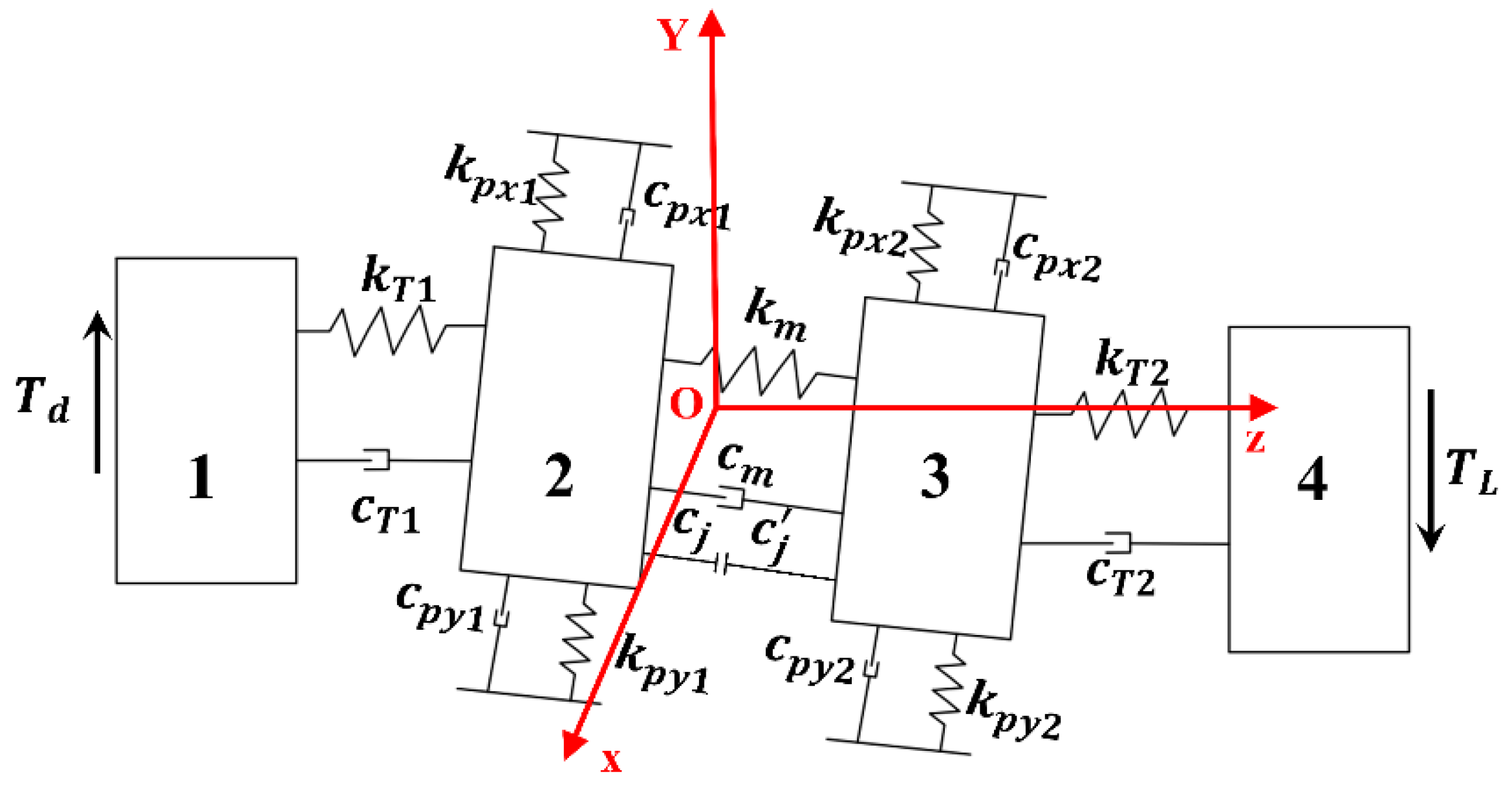
2.1. Dynamic Equation and Parameters
2.2. Solution of Dynamic Equation
3. Fretting Damage Prediction Model for Involute Spline Pairs of an Aero-Engine
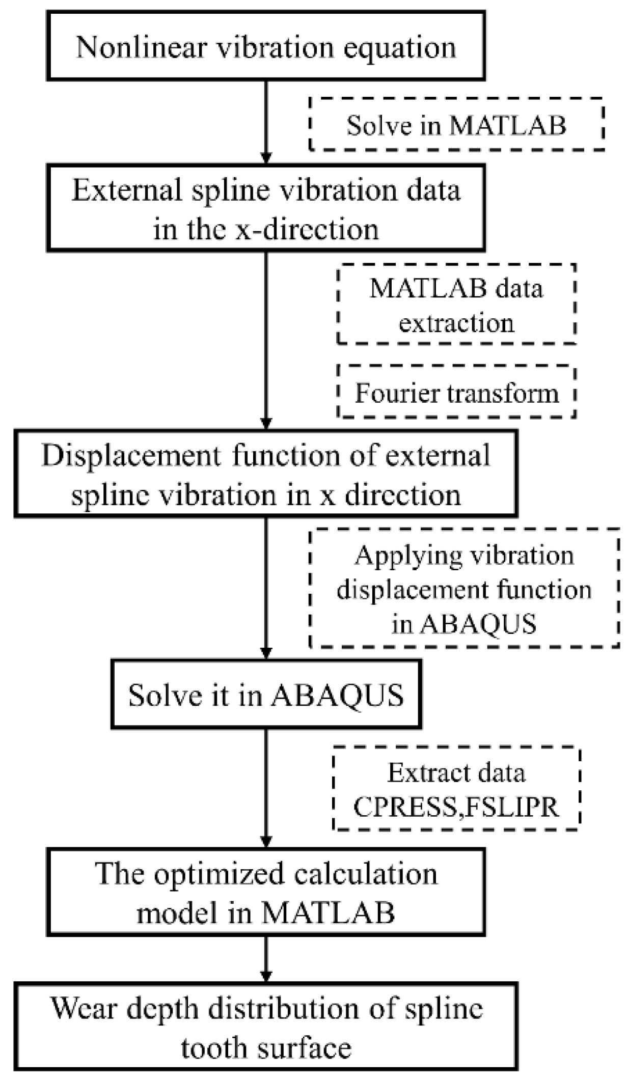
- Solving the differential equation specified in Section 1 utilizing MATLAB results in the derivation of the external spline’s vibration displacement curve, specifically oriented in the x-axis direction.
- Data relevant to the external spline’s vibration displacement in the x-axis direction are gleaned and solved through Fourier transform within MATLAB to yield a time-based function. This function delineates the vibrational displacement’s variability.
- The resultant function is applied to the displacement boundary condition of the spline in the x direction using ABAQUS, an advanced computational platform, and ensuingly resolved.
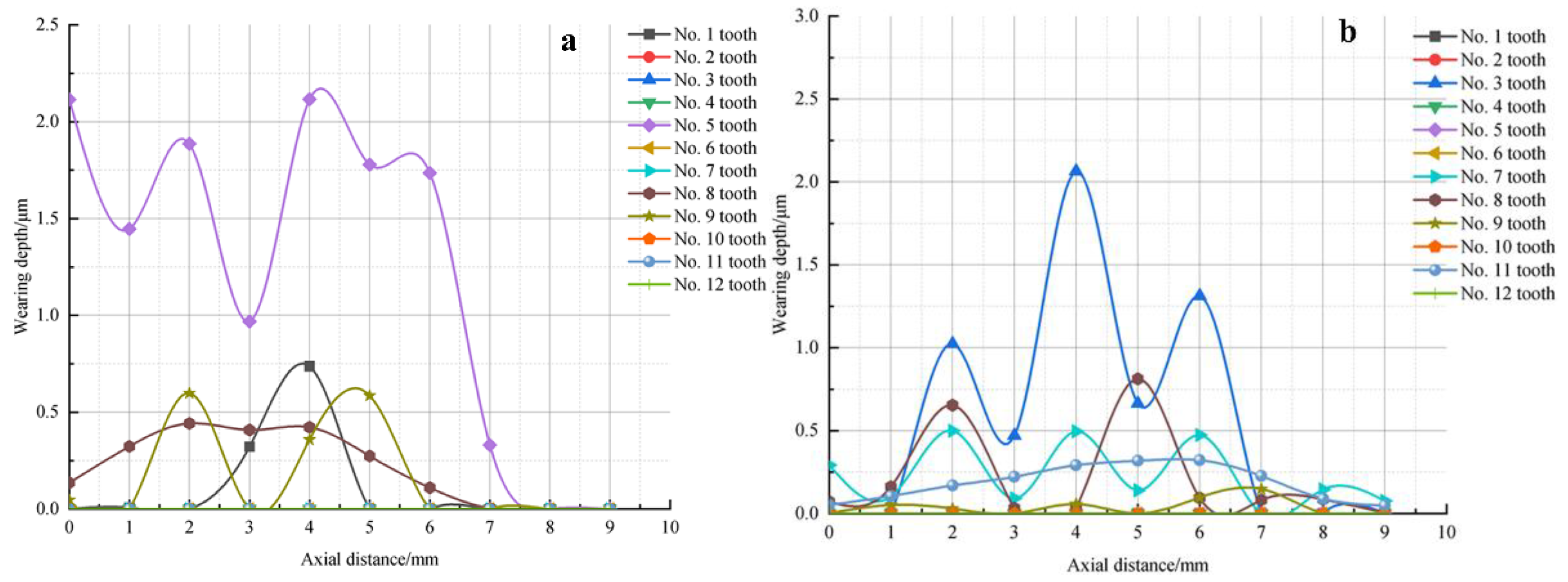
- Post resolution within ABAQUS, the CPRESS and rate FSLIPR in the resultant data file are scrutinized. Subsequently, MATLAB is employed to optimize the Archard fretting wear calculation model, facilitating the estimate of the wear depth distribution on the external spline’s tooth surface in conjunction with different vibrational displacements.
4. Analysis of Nonlinear Vibration Characteristics of Involute Spline Pairs of an Aero-Engine
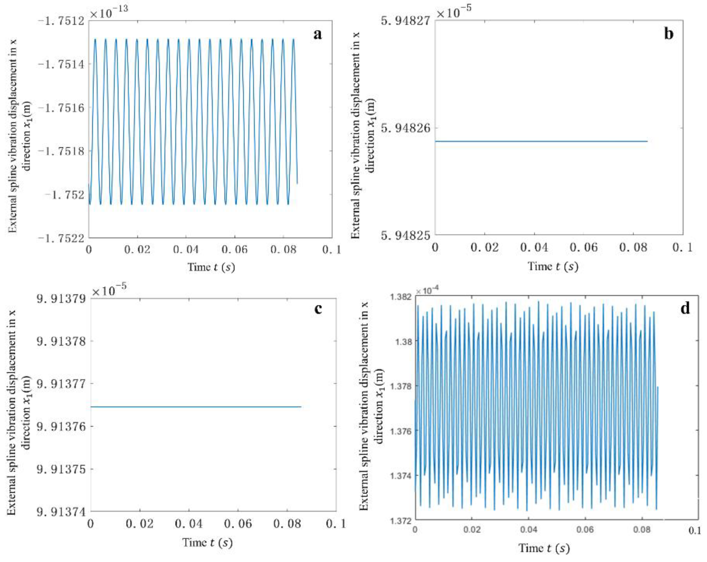
4.1. Study on the Influence of Different Angle Misalignment on Vibration Displacement of Involute Spline Pairs
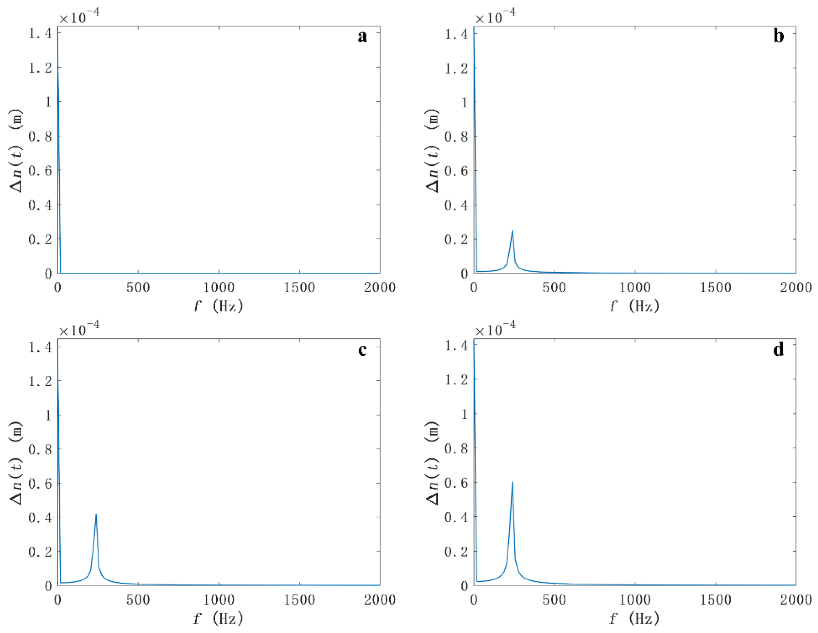
4.2. Study on the Influence of Different Angle Misalignment on Vibration Frequency of Involute Spline Pairs
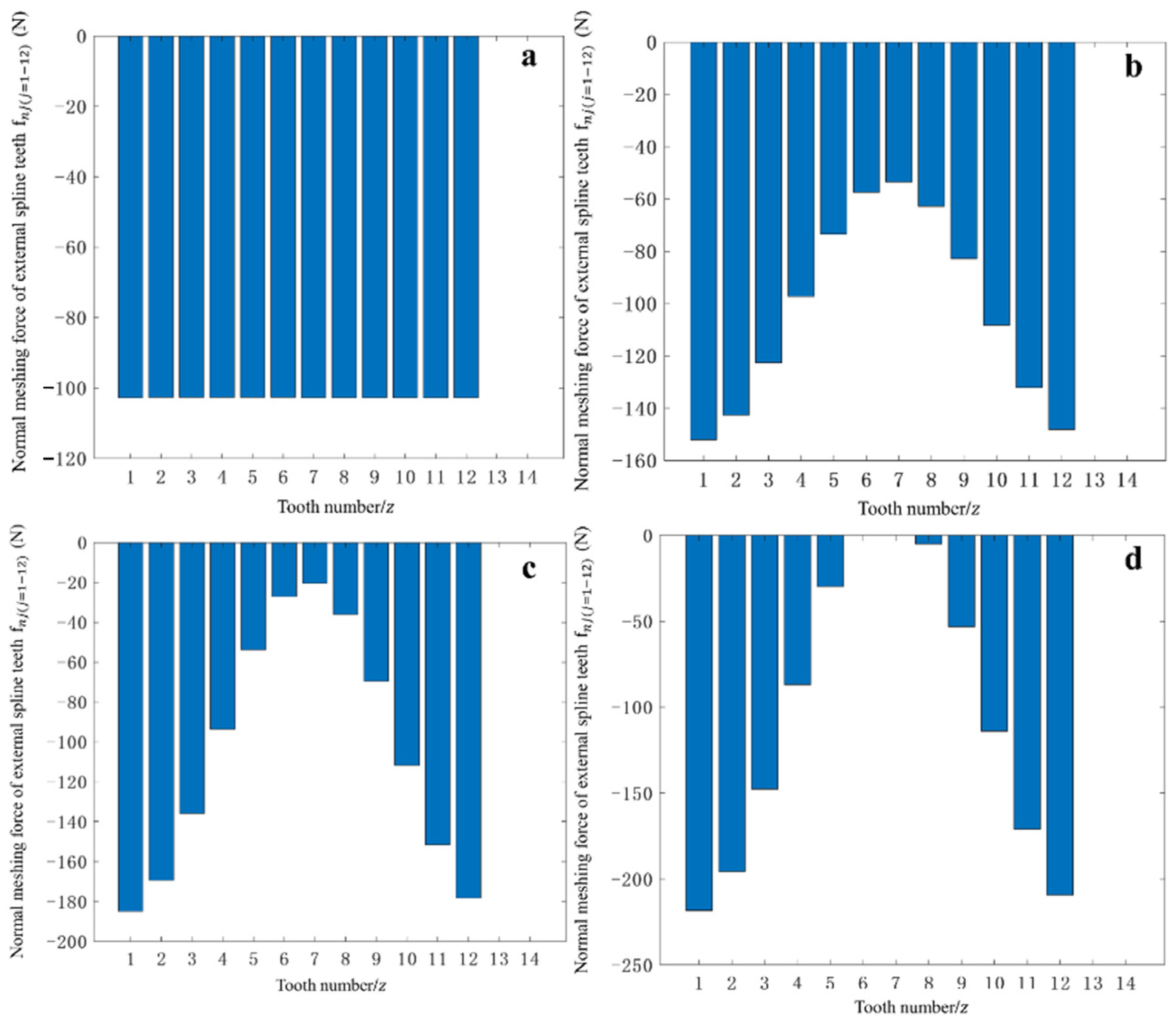
4.3. Study on the Influence of Different Angle Misalignment on the Load of Involute Spline Pairs
5. Analysis of the Influence of Nonlinear Vibration on Fretting Damage of Involute Spline Pairs of an Aero-Engine Based on MATLAB–ABAQUS
5.1. Establishment of Finite Element Model of Involute Spline Pairs of an Aero-Engine
5.2. Finite Element Analysis of Involute Spline Pairs of an Aero-Engine
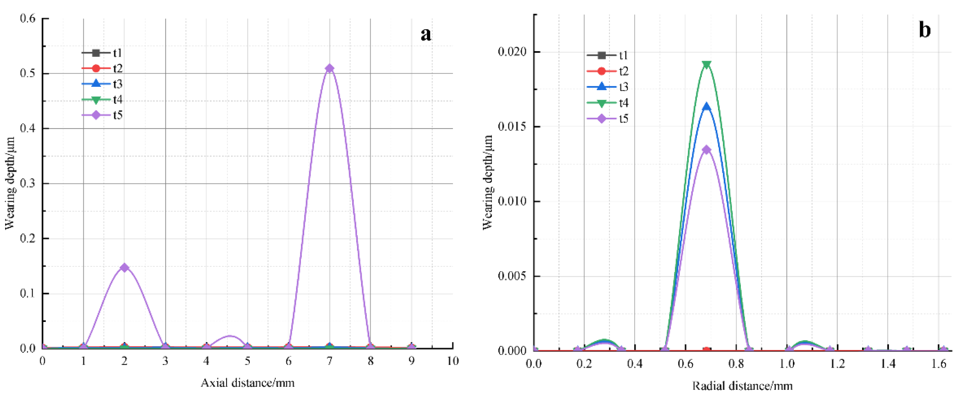
5.2.1. Vibration Displacement of f(e = 0°) Fretting Damage Results
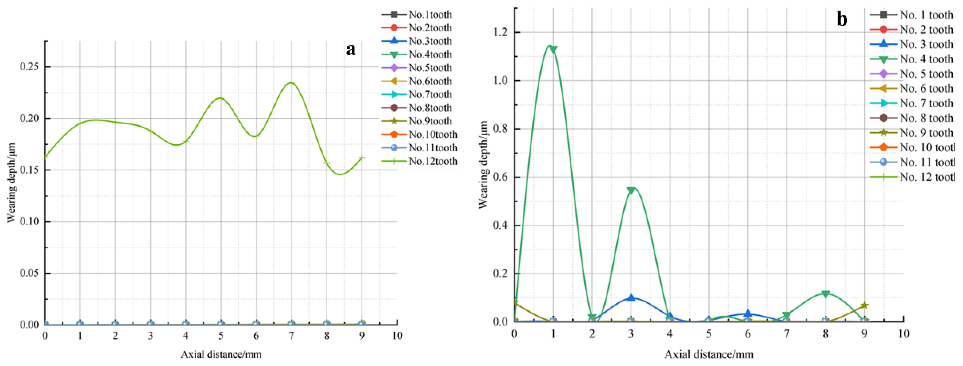
5.2.2. Vibration Displacement of f(e = 0.1°) Fretting Damage Results
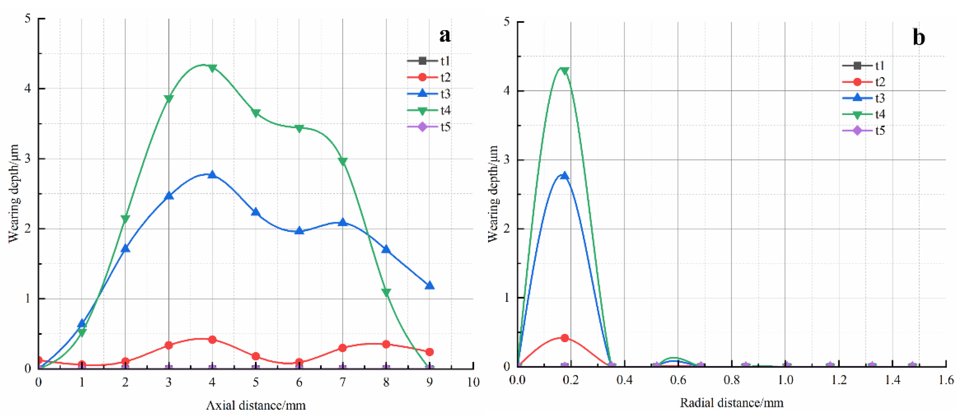
5.2.3. Vibration Displacement of f(e = 0.2°) Fretting Damage Results
5.2.4. Vibration Displacement of f(e = 0.3°) Fretting Damage Results
6. Experiment
6.1. Experimental Introduction
6.1.1. Experimental Device and Principle
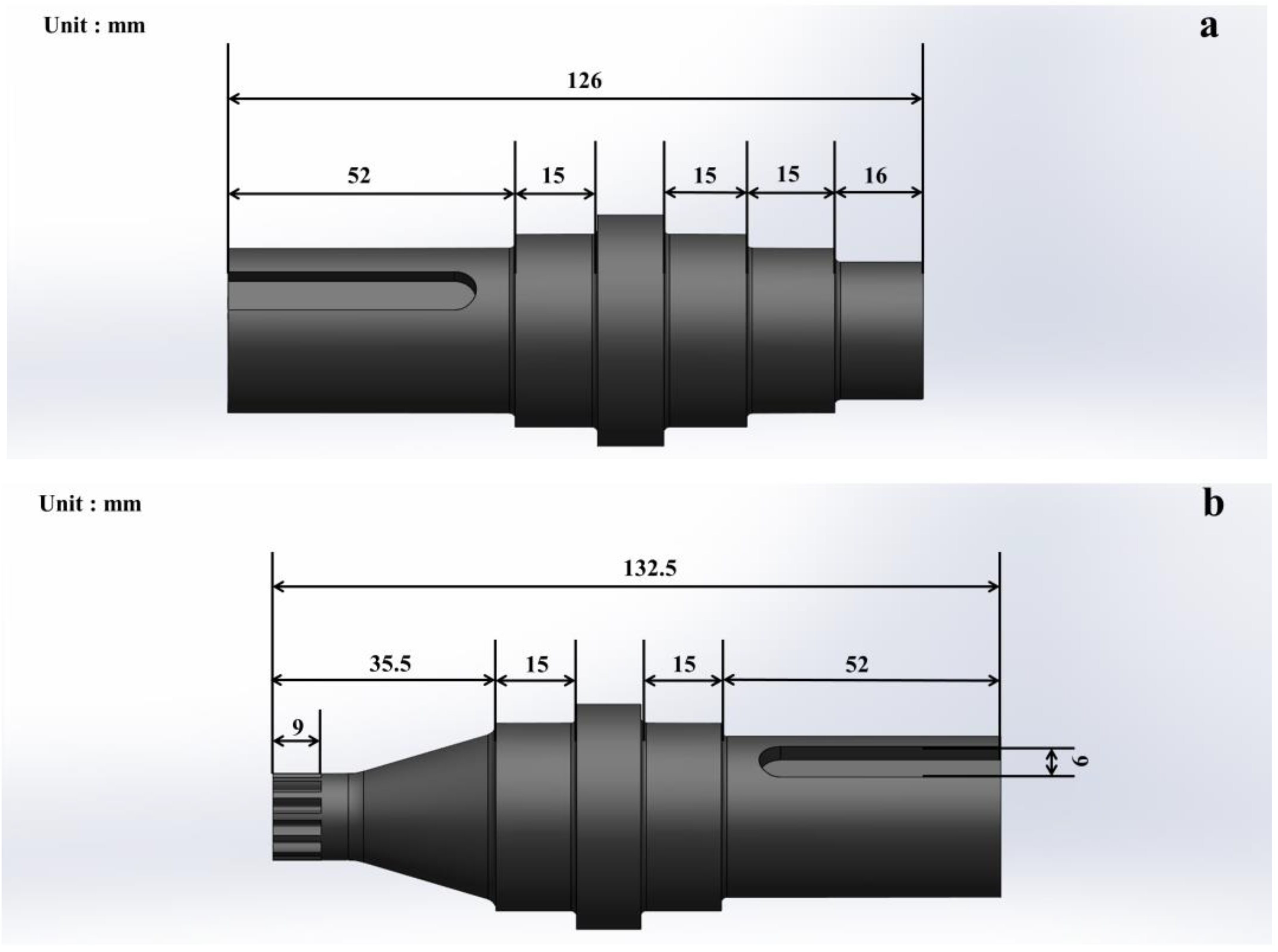
6.1.2. Parameters of Test Piece
6.1.3. Experimental Scheme
6.2. Experimental Procedure
- (1)
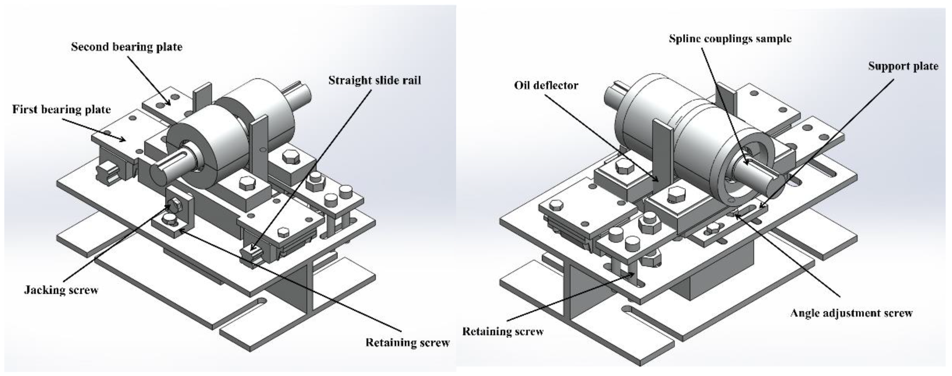
- Spline coupling specimens were positioned onto the two bearings of the working condition simulator. The placement secured the joint components of the two splines equidistantly nestled between the bearings.
- (2)
- The spline angles were adjusted to match the desired bearing displacement; concurrently, the lubrication condition of the spline shaft components was adjusted. This regulated condition emulation accurately replicated the operational circumstances of the spline couplings.
- (3)
- The loading apparatus was configured to the desired load capacity. Thus, the reducer’s deceleration ratio was modulated, and the driving device’s torque was set, achieving the necessary torque for effective spline coupling operation.
- (4)
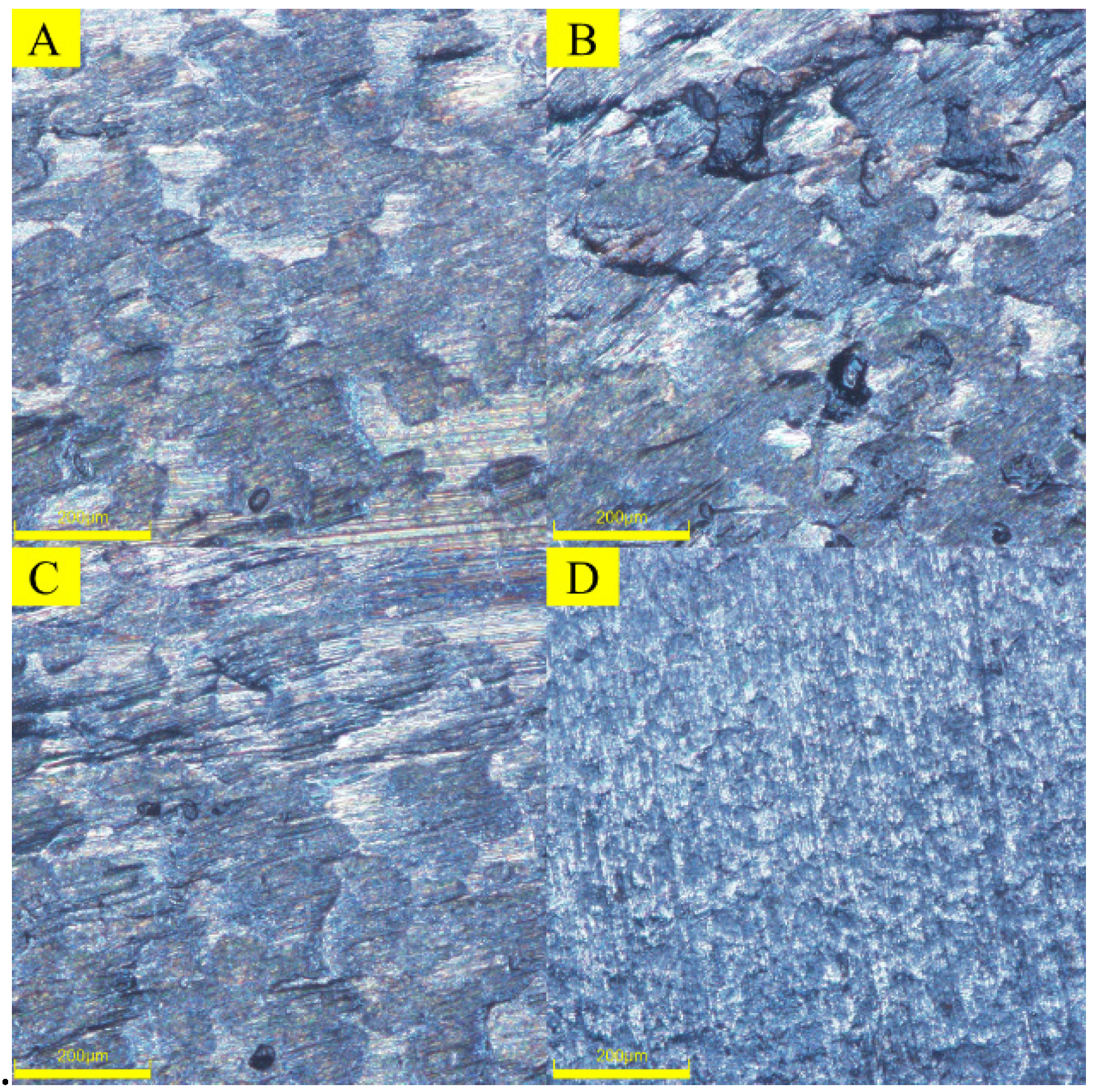
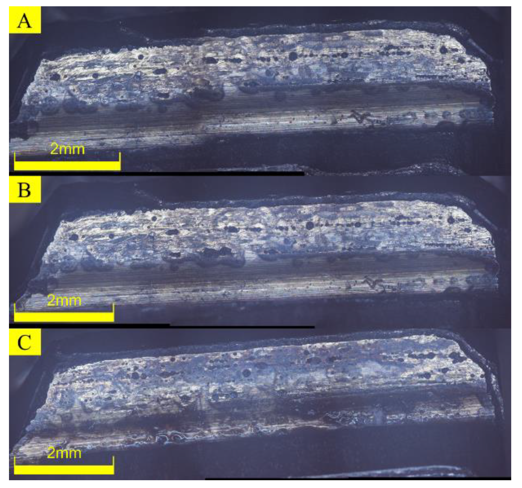
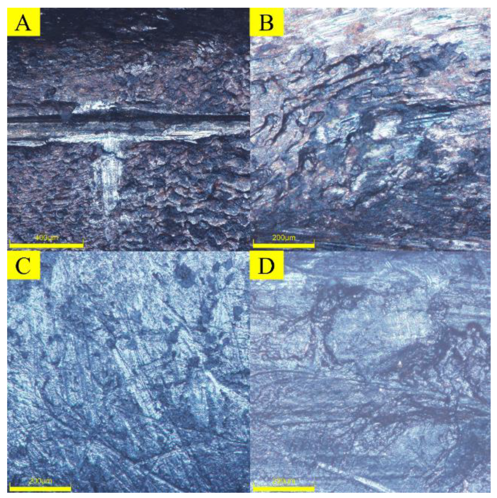
- Upon attainment of the desired operational duration for the spline couplings, the experimental platform was powered down, and the specimens were carefully extracted for subsequent processing and treatment. The intricacies of tooth surface morphology were examined using 3D scanning electron microscopy (SEM) to explore the mechanisms underlying fretting damage. Simultaneously, an Olympus DSX510 digital microscope was deployed to observe the global fretting damage of the spline tooth surface across varied control groups. This process enabled the acquisition of fretting damage distribution data at different locations on the spline secondary tooth surface. This detailed analysis yielded a comprehensive comprehension of the fretting damage distribution across the entirety of the spline secondary tooth surface.
6.3. Experimental Result
6.3.1. The Fretting Damage Results of the External Spline Tooth Surface under All Neutral Conditions
6.3.2. The Fretting Damage Failure Results of External Spline Tooth Surface under the Condition of Angle Misalignment e = 0.1°
6.3.3. The Fretting Damage Failure Results of External Spline Tooth Surface under the Condition of Angle Misalignment e = 0.2°
7. Conclusions
- (1)
- This study employs integrated preceding theories and computational methodologies to effectively resolve a MATLAB-anchored dynamic model pertaining to involute spline pairs in aerodynamic engines. The central area of scrutiny encompasses examination of the influences exerted by variations of angular misalignment on aspects such as vibration displacement, vibration frequency, and the normal forces acting on the meshing interfaces. Observations reveal that the vibration displacement demonstrates an escalation congruent with the augmentation of angular misalignment. Particularly evident is the appreciable increase in vibration displacement when the angular misalignment spans between 0° and 0.1°. Although this ascension persists, the incremental rate decelerates with a further increase in angular misalignment, notably from 0.1° to 0.3°. An eminent amplitude of displacement was observed around a frequency of 250 Hz, and this tended to intensify gradually, signaling a consequent elevation in the alternating stress pervading the system. This escalating stress further stimulates a progressive accrual in the damage induced by the nonlinear vibrations. Additionally, as the angular misalignment escalates, the normal meshing force imposed on each tooth surface exhibits a consistent magnification. Concurrently, the non-uniformity in the distribution of the normal meshing forces across the teeth surfaces exacerbates.
- (2)
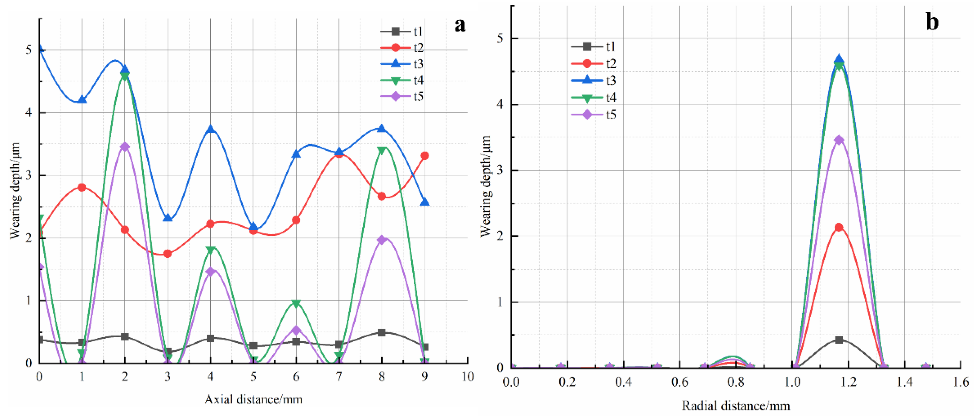
- This study introduces an innovative approach to predicting fretting damage in the involute spline pairs of aerodynamic engines, with the stipulation that fretting wear serves as the primary failure mode. Optimization of the Archard model paves the way towards deriving a novel fretting wear prediction model. Vibration data harnessed from MATLAB was subjected to Fourier transformations, yielding a vibration function which was subsequently integrated into the boundary conditions of the definitive finite element model. The process of analysis and requisite computations were executed in the ABAQUS environment. Findings from the simulation affirm that, contrasted with conditions void of vibrations, the existence of vibrations culminates in a heightened incidence of wear in the external spline teeth. Additionally, certain key teeth experience an intensified degree of wear. A supplemental observation reveals that as the angular misalignment progressively escalates, the fretting wear on the spline teeth becomes dramatically pronounced.
- (3)
- Supplementary to the primary research, an experimental platform was specifically established to investigate the intricacies of fretting damage within the involute spline pairs of aerodynamic engines. A critical examination of the subsequent experimental results substantiated that the archetypal failure mode of fretting damage on the external spline tooth surface was predominantly characterized by fretting wear. Nonetheless, it is noteworthy to mention that fretting fatigue was continually observed in perpetuity throughout the entire fretting cycle. This concurrent presence suggested a competition and meaningful interplay with the defined fretting wear. In an attempt to assiduously quantify the extent of fretting damage in the involute spline pairs of aerodynamic engines, the wear depth was employed as a reliable measure. Moreover, it was unequivocally established that the propensity and severity of fretting damage in these spline pairs escalated correlatively with angular misalignment under the influence of vibration conditions. This discernment not only sheds light on a key contributing factor but also serves to reinforce the credibility and accuracy of the preceding simulation results.
Author Contributions
Funding
Data Availability Statement
Conflicts of Interest
References
- Liu, Z. Bent-Torsional Coupling Vibration Characteristics of Rotor Bearing System. Ph.D Thesis, Chongqing University, Chongqing, China, 2016. [Google Scholar]
- Huang, Z.L.; Song, G.Q.; Zhang, Z.C. Dynamic Analysis of cutting head Rotor System of Roadheader under Two Loads. J. Vib. Meas. Diagn. 2020, 40, 941–947. [Google Scholar]
- Long, X.; Zhang, X.N.; Dong, C. Research on Abnormal wear of spline in Involute. Archit. Eng. Technol. Des. 2020, 6, 4161. [Google Scholar]
- Zeng, G.; Ma, C.J.; Pang, D.Q. Coupling Vibration Characteristics of High linear Speed rotor-Planetary Gear System in Mechatronic Composite Drive. Acta Oramentologica Sin. 2023, 44, 156–164. [Google Scholar]
- Du, W.L.; Li, W.; Jiang, Z. Analysis of flexural and torsional Coupling Vibration of permanent magnet Motor Rotor System of Shearer under Load Excitation. J. Vib. Shock 2023, 42, 237–244. [Google Scholar]
- Wang, P.F.; Yang, Y.; Xu, H.Y. Influence of Static and Dynamic misalignment of Rolling Bearing on Nonlinear Vibration Characteristics of rotating Subsystem. J. Cent. South Univ. 2019, 30, 871–903. [Google Scholar] [CrossRef]
- Wang, L.K.; Wang, A.L.; Yin, Y.J. Vibration characteristics of complex rotor of aeroengine considering support constraints. J. Aerodyn. 2023, 38, 901–912. [Google Scholar]
- Ge, W.W.; Sun, W.L.; Ma, Y.H. Dynamic Characteristics Analysis of Rotor-Bearing System for High Speed Permanent Magnet Motor. Mach. Tool Hydraul. 2021, 49, 169–172. [Google Scholar]
- Xiao, L.; Xu, Y.; Chen, Z.; Zhang, L. Non-linear dynamic response of misaligned spline coupling: Theoretical modeling and experimental investigation. J. Vib. Control 2022, 29, 1590–1605. [Google Scholar] [CrossRef]
- Cura, F.M.; Mura, A. Theoretical and numerical evaluation of tilting moment in crowned teeth splined couplings. Meccanica 2018, 53, 413–424. [Google Scholar] [CrossRef]
- Cura, F.M.; Mura, A. Analysis of a load application point in spline coupling teeth. J. Zhejiang Univ. Sci. 2014, 15, 02–308. [Google Scholar] [CrossRef]
- Curfi, F.; Mura, A.; Gravina, M. Load distribution in spline coupling teeth with parallel offset misalignment. J. Mech. Eng. Sci. 2012, 227, 2195–2205. [Google Scholar]
- Guo, Y.; Lambert, S.; Wallen, R.; Errichello, R.; Keller, J. Theoretical and experimental study on gear-coupling contact and loads considering misalignment, torque, and friction influences. Mech. Mach. Theory 2016, 98, 242–262. [Google Scholar] [CrossRef]
- Zhao, G.; Liu, Z.; Ye, J.; Chen, F. Study on Dynamic Characteristics of Rotor-Misaligned Spline Coupling System. J. Vib. Shock 2009, 28, 78–82. [Google Scholar]
- Zhao, G.; Liu, Z.S.; Ye, J.H.; Chen, F. Misaligned Meshing Force Model of Gear Coupling and Its Influence on Dynamic Characteristics of Rotating Subsystem. J. Harbin Eng. Univ. 2009, 30, 33–39. [Google Scholar]
- Zhao, G.; Guo, J.; Wang, X.; Wang, Y.L. Research on Bend-Torsional Coupling Vibration of Rotor-Gear Coupling System. J. Aerosp. Power 1999, 109, 61–65. [Google Scholar]
- He, C.; Gu, Y.; Yang, K. Characteristics of Bent-Torsional Coupling Vibration of Misaligned Rotor in Gear Coupling. J. Mech. Strength 2005, 75, 725–729. [Google Scholar]
- Fu, B.; Zhou, J.; Peng, B.; An, X. Characteristics of Misalignment flexural and torsional Coupling Vibration of Fixed Rigid Coupling. J. Huazhong Univ. Sci. Technol. (Nat. Sci. Ed.) 2007, 34, 96–99. [Google Scholar]
- Jing, J.; Gao, T.; Chen, C. The study on spline coupling dynamic coefficients and its imapact on rotor stability. In Proceedings of the ICSV2016-23rd International Congress on Sound and Vibration: From Ancient to Modern Acoustics, Shanghai, China, 10–14 July 2016; State Key Laboratory of Mechanical System and Vibration, Shanghai Jiao Tong University: Shanghai, China, 2016. From Ancient to Modern Acoustics. [Google Scholar]
- Jing, J.P.; Gao, T.; Mei, Q. Stability Analysis of Spline Connected Rotor System. Noise Vib. Control 2016, 36, 40–45. [Google Scholar]
- Yang, G.L.; Zhu, L.L.; Zhao, L.C. Axial System Angle Misalignment Analysis of Radial Vibration Characteristics. Mach. Des. Manuf. 2018, 10, 125–126. [Google Scholar]
- Tuckmantel, F.W.D.S.; Cavalca, K.L. Vibration signatures of a rotor-coupling-bearing system under angular misalignment. Mech. Mach. Theory 2019, 133, 559–583. [Google Scholar] [CrossRef]
- Zhang, X.; Su, X.; Lu, H. Analysis of dynamic characteristic for misalignment-spline gear shaft based on whole transfer matrix method. J. Vibro Eng. 2018, 20, 1392–1408. [Google Scholar]
- Mura, A.; Francesca, C.; Molfetta, A.D. Investigation of bearings overloads due to misaligned spline shafts. Procedia Struct. Integr. 2018, 5, 52–57. [Google Scholar] [CrossRef]
- Patil, S.B.; Patil, S.R. Experimental and numerical analysis of a load distribution along the length of contact in involute spline shaft. Int. J. Adv. Technol. Eng. Explor. 2019, 6, 30–44. [Google Scholar] [CrossRef]
- Xue, X.; Wang, S.; Yuan, R. Nonlinear Dynamic Characteristics of Involute Spline Pair. J. Harbin Inst. Technol. 2015, 47, 107–111. [Google Scholar]
- Xue, X.Z.; Wang, S.M. Dynamic Characteristics and Load Coefficient Analysis of Involute spline pairs. Adv. Mater. Res. 2014, 890, 450–454. [Google Scholar] [CrossRef]
- Xue, X.Z.; Wang, S.M.; Yuan, R. Investigation of Load Distribution among Teeth of an Aero-Engine Spline Coupling; Springer: Berlin/Heidelberg, Germany, 2016; Volume 367, pp. 1155–1162. [Google Scholar]
- Chen, Y.; Li, J. Review on Bend-Torsional Coupled Vibration of Turbo-Generator Shafting; Turbine Technology: Harbin, China, 2012; Volume 54, pp. 161–164. [Google Scholar]
- Liu, Z.; Cui, Y.; Huang, W. Study on Nonlinear Dynamics Characteristics of Coupled Flexural and Torsional Vibration of Rotor. China Mech. Eng. 2003, 5, 69–71. [Google Scholar]
- Zheng, W.; Wang, S.; Jie, X. Research on Fretting Wear Mechanism and Wear Prediction Method of Aircraft Involute Spline. Ph.D Thesis, Northwestern Polytechnical University, Xi’an, China, 2017. [Google Scholar]
- Xue, X.; Huo, Q.; Liu, J. Nonlinear Vibration Characteristics of the Involute Spline Coupling in Aeroengine with the Parallel Misalignment. Int. J. Aerosp. Eng. 2021, 2021, 1–19. [Google Scholar] [CrossRef]
- Xue, X.; Huo, Q.; Zheng, J.; Chen, X.; Qin, L. Research on anti-fretting wear of aviation involute spline pair based on tooth profile modification. China Mech. Eng. 2019, 30, 2447–2455. [Google Scholar]
- Xue, X.Z.; Huo, Q.X.; Hong, L. Fretting wear-fatigue life prediction for aero-engine’s involute spline pairs based on ABAQUS. J. Aerosp. Eng. 2019, 32, 1–9. [Google Scholar] [CrossRef]


| Parameter | Parameter Value | Units |
|---|---|---|
| Parameter | Value |
|---|---|
| Tooth number | 12 |
| Modulus () | 1.25 |
| Internal spline trunnion () | 25 |
| External spline trunnion () | 8 |
| Contact length () | 9 |
| Element Sizes | Element Quantity | Stress Result (Max) | Discrepancy | |
|---|---|---|---|---|
| Figure 8a | 0.5 | 51,264 | 89 | 8.5% |
| Figure 8b | 0.5625 | 42,480 | 82 | / |
| Figure 8c | 0.6429 | 36,580 | 70 | 9.7% |
| Parameter | Value | Parameter | Value |
|---|---|---|---|
| Parameter | Value | Parameter | Value |
|---|---|---|---|
| Parameter | Value | Parameter | Value |
|---|---|---|---|
| Parameter | Value | Parameter | Value |
|---|---|---|---|
| Material Name/Material Parameter | 9310 | 32Cr3MoVA |
|---|---|---|
| Strength of extension | ||
| Yield strength | ||
| Extend rate | ||
| Shrinkage rate | ||
| Heat treatment | Hardening; Oil cooling; Tempering; Water cooling; Air cooling | Hardening; Oil cooling; Air cooling; Tempering; Air cooling; Tempering resistance; Argon shield |
| Average Vickers hardness after carbonization | 529.21 | 521.25 |
| Experiment Group Number | Internal Spline Material | External Spline Material | Angle Misalignment | Lubrication | Induration | Rotate Speed |
|---|---|---|---|---|---|---|
| 1 | 9310 | 32Cr3MoVA | 0 | Grease lubrication | All hardened (Carbonized) | 1400 |
| 2 | 9310 | 32Cr3MoVA | 0.1 | Grease lubrication | All hardened (Carbonized) | 1400 |
| 2 | 9310 | 32Cr3MoVA | 0.2 | Grease lubrication | All hardened (Carbonized) | 1400 |
Disclaimer/Publisher’s Note: The statements, opinions and data contained in all publications are solely those of the individual author(s) and contributor(s) and not of MDPI and/or the editor(s). MDPI and/or the editor(s) disclaim responsibility for any injury to people or property resulting from any ideas, methods, instructions or products referred to in the content. |
© 2023 by the authors. Licensee MDPI, Basel, Switzerland. This article is an open access article distributed under the terms and conditions of the Creative Commons Attribution (CC BY) license (https://creativecommons.org/licenses/by/4.0/).
Share and Cite
Xue, X.; Li, Y.; Lin, K.; Sui, L.; Jiang, Y.; Zhang, N. A Study on the Influence of Nonlinear Vibration on Fretting Damage of Involute Spline Pairs in Aero-Engines. Lubricants 2023, 11, 515. https://doi.org/10.3390/lubricants11120515
Xue X, Li Y, Lin K, Sui L, Jiang Y, Zhang N. A Study on the Influence of Nonlinear Vibration on Fretting Damage of Involute Spline Pairs in Aero-Engines. Lubricants. 2023; 11(12):515. https://doi.org/10.3390/lubricants11120515
Chicago/Turabian StyleXue, Xiangzhen, Yifan Li, Kuan Lin, Liqi Sui, Yiqiang Jiang, and Ning Zhang. 2023. "A Study on the Influence of Nonlinear Vibration on Fretting Damage of Involute Spline Pairs in Aero-Engines" Lubricants 11, no. 12: 515. https://doi.org/10.3390/lubricants11120515
APA StyleXue, X., Li, Y., Lin, K., Sui, L., Jiang, Y., & Zhang, N. (2023). A Study on the Influence of Nonlinear Vibration on Fretting Damage of Involute Spline Pairs in Aero-Engines. Lubricants, 11(12), 515. https://doi.org/10.3390/lubricants11120515