Article

Study on the Lubricating Characteristics of the Oil Film of the Slipper Pair in a Large Displacement Piston Pump

1
School of Mechatronics Engineering, Henan University of Science and Technology, Luoyang 471003, China
2
China Railway Engineering Equipment Group Co., Ltd., Zhengzhou 450001, China
*
Author to whom correspondence should be addressed.
Lubricants 2023, 11(12), 521; https://doi.org/10.3390/lubricants11120521
Submission received: 6 November 2023 / Revised: 3 December 2023 / Accepted: 6 December 2023 / Published: 8 December 2023

Abstract

:
Due to the large size of the bottom surface, the slipper pair of the large displacement piston pump (LDPP) will form a larger linear speed difference in the inner and outer positions of the slipper relative to the center of the swash plate during high-speed rotation. It is more likely to lead to the slipper overturning, which makes the slipper partially worn. To make improvements, the comprehensive performance of the slipper pair of the LDPP, the motion law of the slipper pair of the LDPP was explored. Firstly, a mathematical model of the oil film thickness of the slipper pair of the LDPP under the state of residual compression force is established, based on the consideration of the linear velocity difference formed by the high-speed rotation of the large bottom surface slipper and the theory of dynamics and thermodynamics. Secondly, the impact of rotational speed, piston chamber pressure and oil temperature on the oil film thickness of the slipper pair was simulated and analyzed. Finally, to measure the oil film thickness of the slipper pair, oil film thickness measuring equipment was created, and the accuracy of the mathematical model was verified. The study revealed the changing rules of the oil film thickness and tilt angle of the bottom surface of the slipper pair under various working conditions. The consistency of the simulation and test findings demonstrates that the mathematical model can accurately describe influencing elements and changing rules of the LDPP slipper pair’s oil film lubrication characteristics.

1. Introduction

The hydraulic system, as the basic component of big mechanical equipment such as construction machinery and mining equipment, exhibits a development trend of high pressure, huge flow, and high reliability. Due to its high pressure and high flow properties, the piston pump has become the most extensively utilized hydraulic power component in current large-scale hydraulic systems [1,2,3,4,5]. The slipper pair is the most vulnerable portion of the piston pump friction pair because it has the most complicated motion mechanism and working conditions in the large displacement piston pump (LDPP). When the axial piston pump is working, there is an oil film formed between two sliding surfaces of the slipper pair to support and lubricate them. The oil film cannot be too thin or too thick; too thin will cause excessive wear and slipper burning damage, and too thick will have a small sealing effect, large leakage, and low volume efficiency [6,7,8,9]. The development of this type of pump is limited by the problem of friction film lubrication. As a result, research on the lubricating characteristics of slipper pairs of LDPP has become a hot and tough industry subject.
In the actual working process, the working condition of the LDPP is more complicated, and it is often affected by load fluctuations and sudden impact loads, so that the anti-overturning moment generated by the dynamic pressure effect cannot balance the overturning moment of the slipper in time, resulting in the tilt angle of the slipper further increasing and the minimum oil film thickness decreasing. In this process, the outer edge of the slipper is easily subjected to solid contact or collision with the swash plate surface, causing friction and wear on the outer edge of the slipper and destroying the original static pressure support structure. Thus, the overall performance and life of the piston pump are reduced [10,11,12,13,14]. Due to the lack of clear research on the partial wear motion law of the slipper pair of the LDPP, in order to promote the development of the LDPP and improve its overall performance, it is very meaningful to study the motion law of the slipper pair in its actual working condition.
Many specialists and researchers have undertaken extensive research on the lubricating properties of slipper pairs. Schenk et al. [15] developed a transient lubrication model between slipper and swash plate by taking non-isothermal fluid, boundary pressure, and thermal deformation into account and investigating the effect of transient deformation on oil film pressure. Rokala et al. [16] constructed a slipper test platform, used three displacement sensors mounted on the slipper slipper’s auxiliary plate to measure the distance between the sensor probe and the swash plate, indirectly calculated the displacement between the swash plate and the slipper bottom surface, and then computed the oil film thickness field of the slipper pair using the method of determining a plane by three points. Tang et al. [17,18] created an axial piston pump slipper pair thermoelastohydrodynamic lubrication model. The model considers the interaction of elastic hydromechanical behavior and the viscosity temperature impact. Zhao et al. [19] proposed a modeling method for the oil film thickness field and further established the force model of the slipper pair of the digital valve distribution axial piston pump and the numerical solution model of the oil film lubrication. The effects of swash plate rotational speed and tilt angle on the lubrication characteristics of oil film were analyzed. The results show that increasing the swash plate rotation speed and the swash plate inclination angle is beneficial to optimizing the oil film lubrication performance. Jiang et al. [20,21] established a comprehensive numerical simulation technique for predicting slipper boot lubrication performance and devised three micro-structures of slipper shoes, namely micro-chamfer, micro-fillet, and micro-step, to improve slipper boot lubrication performance. Song et al. [22] provided a numerical analysis approach for the lubricating film characteristics of axial piston pumps that takes thermal factors into consideration and uses a multi-disciplinary coupling model to increase piston pump energy efficiency. Shi et al. [23] developed dynamic lubrication models of oil film thickness field, temperature field, and pressure field for slipper/swash plate pairs’ local wear. Zhou et al. [24] evaluated the dynamic lubrication performance of axial plunger’s slipper/swash plate interface and performed an experimental study on the slipper’s attitude under varying load pressure and speed, with thickness of the lubricating oil film as primary measuring parameter. The test results show that in high pressure areas, the inclination angle of the slipper is smaller. In low pressure areas, the inclination angle of the slipper is larger. Ma et al. [25] devised an approach for analyzing wear behavior of a swash plate/slipper pair founded on the elastohydrodynamic lubrication model. The linked internal elements impacting wear behavior are discovered based on an evaluation of film thickness, taking into consideration all structure, working conditions, and material characteristics parameters. Zhang et al. [26,27] used test equipment to investigate the lubricating characteristics of slipper pairs in the spin state. Shen et al. [28] considered the effect of hot wedge force and dynamic pressure on the slipper and established the force model under the state of residual compression force. The effects of different load pressures and rotational speeds on the oil film thickness and power loss of the slipper pair are studied. The results show that the oil film thickness decreases when the working pressure increases. As the rotational speed increases, the thickness of the oil film will increase.
According to the current research status of slipper pair lubrication characteristics, recent studies on the oil film properties of slipper pairs primarily focus on small and medium displacement piston pump slipper pairs. Due to the difficulty of testing LDPP, studies on the oil film properties of slipper pair of LDPP are still lacking. Moreover, due to the large slipper bottom area, the slipper of LDPP will form a linear velocity difference in the inner and outer positions of the relative swash plate center during high-speed rotation, resulting in a significant difference in the slipper pair’s change law of the oil film thickness from the slipper pair of the medium and small displacement piston pumps. As a result, the lubricating characteristics of the LDPP slipper pair should be investigated.
In order to promote the development of LDPP and the development of key components, this paper uses the slipper pair of the LDPP as the research object. The method of combining simulation with experiment, the aim is to reveal the motion rules of slipper pairs of LDPP under different working conditions. On the basis of considering the linear velocity difference formed between the inner and outer positions relative to the swash plate center when the large bottom surface slipper rotates at high speed, combined with the hot wedge effect and the heat conduction relationship, a mathematical model of the lubrication characteristics of the slipper pair of the LDPP is established. And through the construction of a LDPP slipper pair oil film lubrication characteristics test rig, the impact of rotational speed, piston chamber pressure, and oil temperature on the oil film thickness of an LDPP slipper pair was investigated. This research establishes a theoretical foundation for developing a mathematical model of the oil film characteristics of slipper pairs of LDPP. It also serves as a guideline for the development of critical components for LDPP.

2. Modeling of Oil Film Thickness of Slipper Pair of LDPP

The main driving pump of a shield is a classic example of an LDPP. In this paper, the oil film thickness of the slipper pair is modeled by taking the main driving pump of the shield at a displacement of 750 mL/r as the research object. The residual compression force design method is adopted for the slipper of the main driving pump of the shield. The bottom surface of the sliding slipper has a three-ring structure, as shown in Figure 1, with the inner support ring, the sealing ring, and the outside support ring placed sequentially from the inside out and an annular oil groove arranged between each ring. There are oil gaps on the inner and outer supporting rings to ensure that the oil pressure of the inner oil chamber and the inner oil tank is equal, and the oil pressure of the outer oil tank is the same as that of the shell, in order to avoid additional static pressure in the annular oil tank.

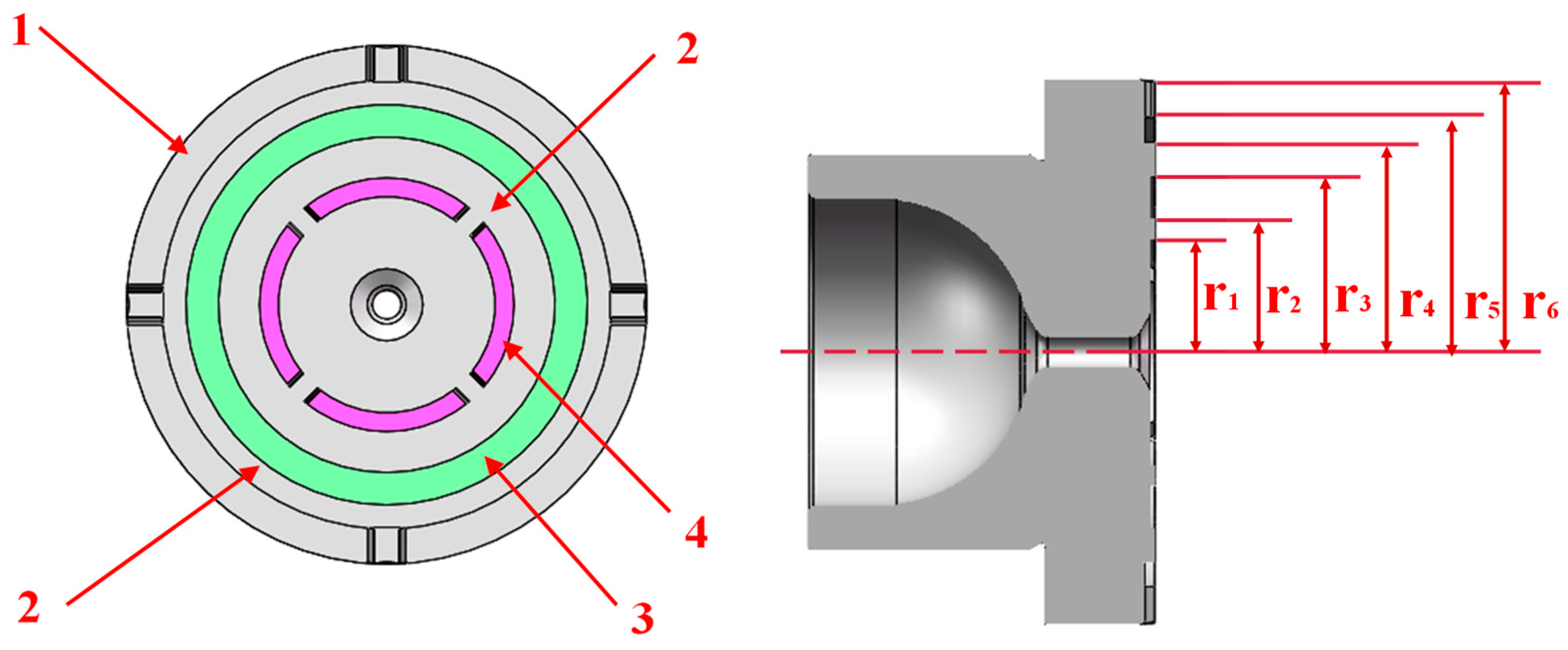
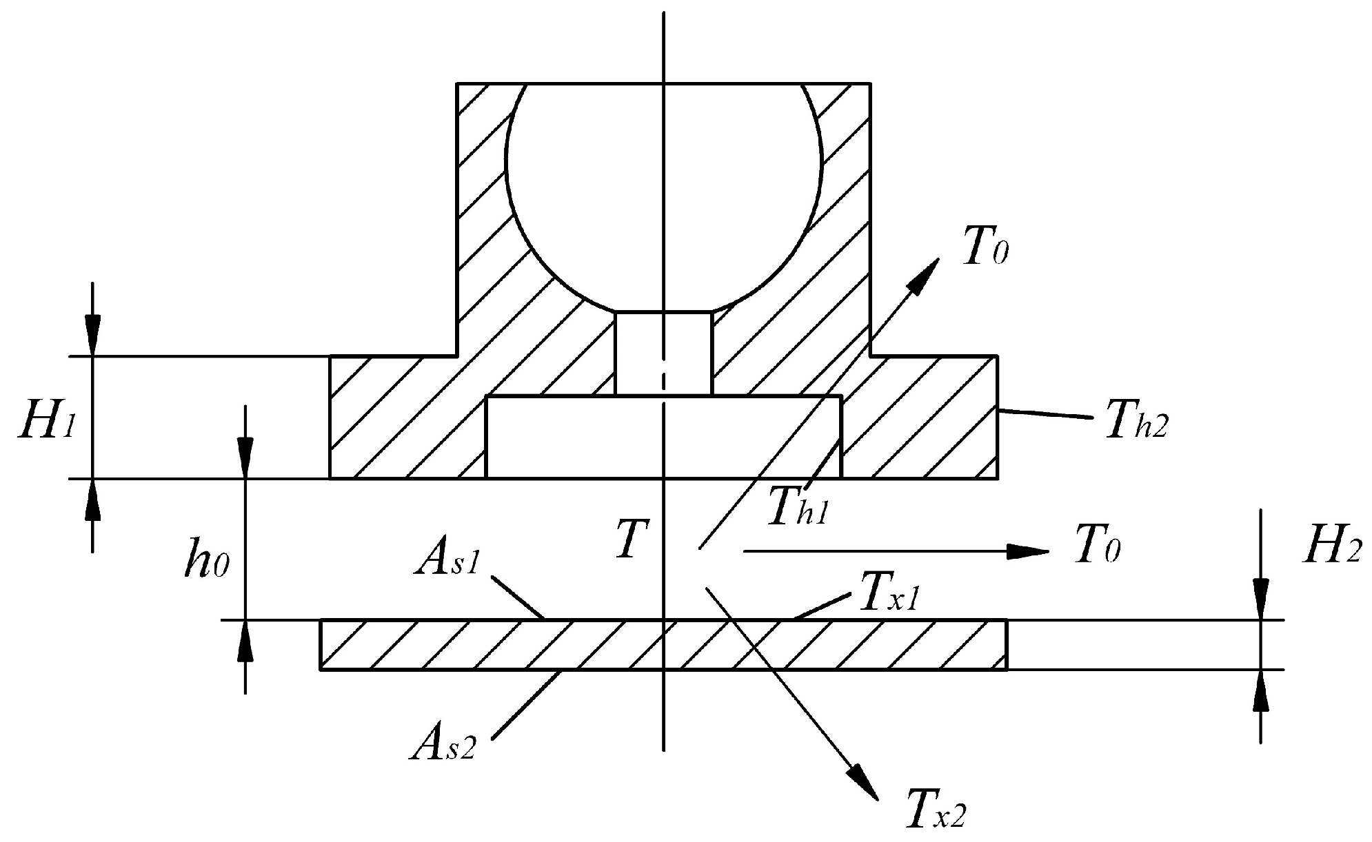
2.1. Force Analysis of Slipper Pair

The force on the sliding slipper pair of the LDPP during movement is shown in Figure 2. The force on the slipper is primarily: F1 is the force exerted by the bottom of the piston on the bottom of the slipper. F2 is the spring’s compression force. F3 is the axial inertia force generated by the piston slipper assembly. F0 is the hydraulic support force generated by incomplete static pressure support on the bottom surface of the slipper.
The hydraulic support force F0 generated by the incomplete balanced static pressure support on the bottom surface of the sliding slipper is [18]:
F 0 = π ( r 4 2 r 3 2 ) 2 ln ( r 4 / r 3 ) p r
where p r for the center oil chamber pressure.
For the slipper-piston assembly, the oil enters the slipper-oil chamber through the piston chamber through the damping hole. According to the pressure loss along the pipe flow, the pressure-flow characteristic here can be acquired as [21]:
q 1 = π d 1 4 128 μ l ( p s p r )
where l is the length of the damping hole; d 1 is the diameter of the damping hole.
The pressure-flow characteristics between the slipper and the swash plate can be expressed as [29]:
q 2 = π h 3 6 μ ln ( r 4 / r 3 ) p r
It can be obtained from the flow continuity equation:
p r = p s 1 + 64 l h 3 3 d 1 4 ln ( r 4 / r 3 )
In summary, the force balance analysis of the slipper pair under the state of residual compression force is carried out, and the residual compression force can be expressed as:
F s = F 1 cos ( γ + β ) + F 2 cos γ + F 3 cos ( γ + β ) π ( r 4 2 r 3 2 ) 2 ln ( r 4 / r 3 ) 1 1 + 64 h 3 3 d 1 4 ln ( r 4 / r 3 ) p s
From the slipper movement process known that there is relatively high-speed movement between the two friction pairs of the slipper and the swash plate, and the energy consumed by the sliding friction force is converted into heat, which makes the oil film of the slipper produce a hot wedge force. The thermal wedge supporting force can be expressed as [30]:
N = 16 μ 2 ω 2 γ 0 r 4 4 G c e ρ g h 4 0 π ( r + r 4 cos φ ) 2 sin φ d φ
where μ is the dynamic viscosity coefficient of oil; ω is the angular velocity; γ 0 is the volumetric expansion coefficient of oil; ρ is the density of the oil; c e is the specific heat capacity of the oil; g is the gravitational acceleration; G is thermal energy equivalent; h is the thickness of the oil film; r is the vector diameter corresponding to the first corner of the elliptic motion trajectory.
According to the force balance relationship, the relationship between the hot wedge supporting force N and the residual compression force Fs can be expressed as:
F s = N
By combining the above Equations (5)–(7), we can obtain the 7th-order differential equation about the oil film thickness h. After solving, the only positive real number that meets the conditions is the oil film thickness of the bottom surface of the slipper at the corresponding position.

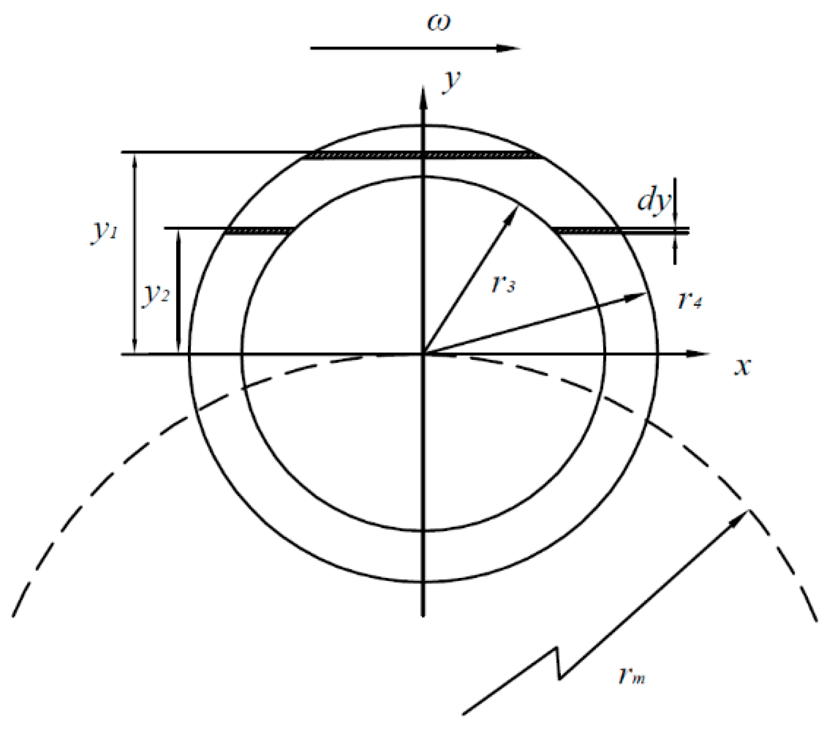
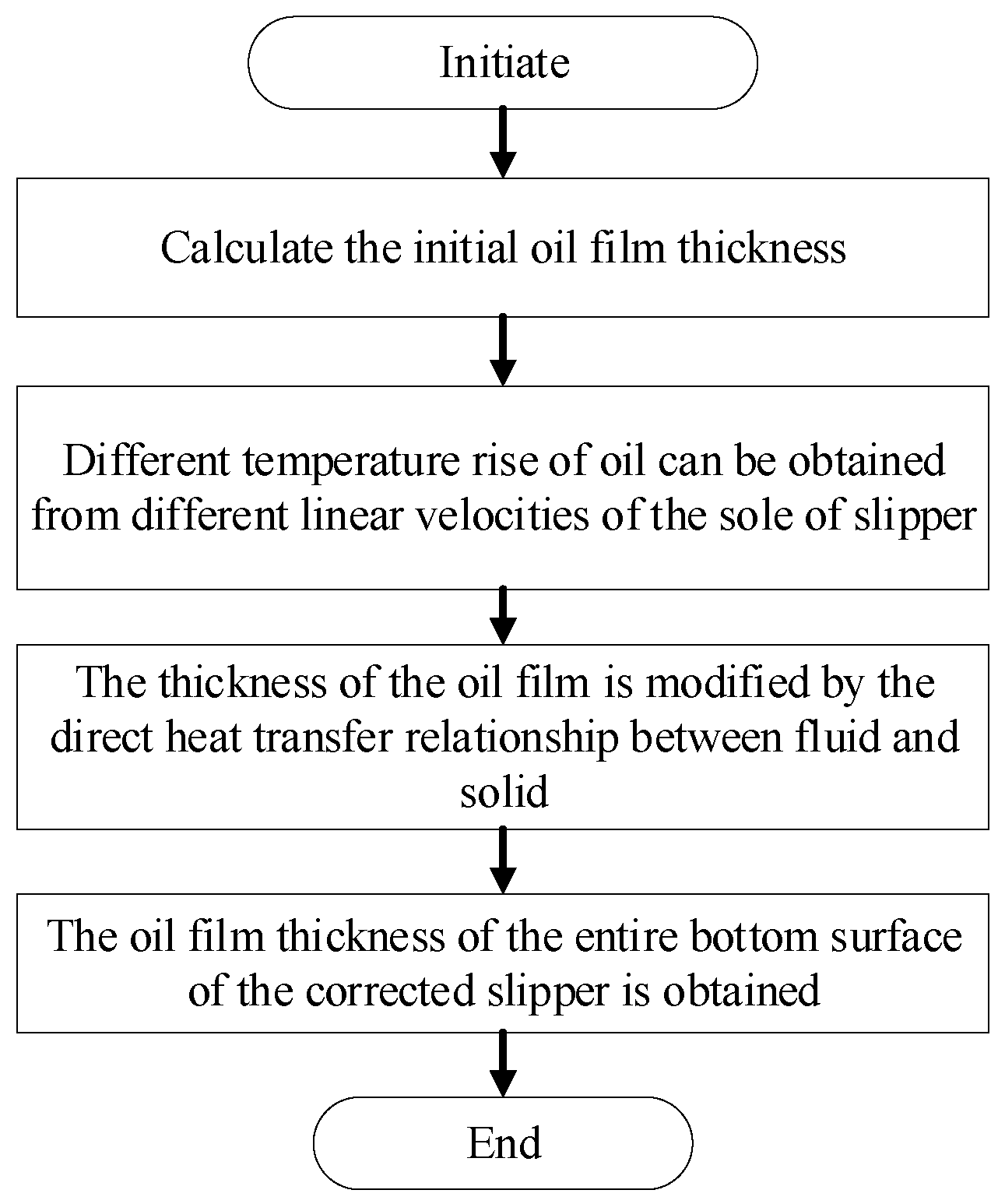
2.2. Oil Film Thickness Model of Slipper Pair

The above solution calculates the oil film thickness of slipper bottom by taking the linear velocity of the slipper center as the linear velocity of the complete sealing tape plane. However, because of the large annular size of the slipper bottom surface of the LDPP, the linear velocity difference between the top and bottom two positions of the slipper bottom surface is large, and different linear velocities will produce different temperature rises, resulting in different oil expansion volumes and influencing the oil film thickness. According to reference [31], differential processing was applied to the slipper’s sealing belt, and the thermal wedge effect diagram of the slipper motion at various linear velocities was generated, as illustrated in Figure 3.
In Figure 3, the friction power loss of d y width shear flow at the sealing belt y 1 of the slipper is:
d E j 1 = 2 μ r 4 2 y 2 ( R f + y ) 2 ω 2 h d y
In Figure 3, the friction power loss of d y width shear flow at the sealing belt y 2 of the slipper is:
d E j 2 = 2 μ ( r 4 2 y 2 r 3 2 y 2 ) ( R f + y ) 2 ω 2 h d y
The flow rate through the section at the sealing belt y 1 of the slipper is:
q j 1 = h ( R f + y ) ω r 4 2 y 2
The flow rate through the section at the sealing belt y 2 of the slipper is:
q j 2 = h ( R f + y ) ω ( r 4 2 y 2 r 3 2 y 2 )
If the heat dissipation of the oil is ignored, the oil film of slipper pair is regarded as adiabatic system, and the total friction power loss E j of the sealing belt of slipper pair is completely transformed into the thermal power increment of oil film. The temperature rise generated by the oil is Δ T . The expression is:
ρ c e q j Δ T = d E j
The Equation (12) can be obtained by integrating it simultaneously:
r 4 r 4 ρ c e q j Δ T = r 4 r 4 d E j
To sum up, by substituting formulas (8)–(12) into formula (13), the temperature rise because of the relative slide between the slipper and the swash plate is as follows:
Δ T j = 2 μ ρ c e h 2 ( R f + y j ) ω
In the above formula, y j is the value of different positions in the direction y of the slipper seal belt, and its range is r 4 , r 4 ; Δ T j is the temperature rise at the corresponding position.
Due to the temperature change caused by the thermal effect, the volume of oil is expanded by heat, which changes the thickness of the oil film of slipper pair. The expansion height of the oil film per unit volume of the sliding slipper pair under different linear speed conditions is:
h j = h ( 1 + 1 / 3 γ 0 Δ T j )
where α 0 is the volume expansion coefficient of the oil.
During slipper movement, heat exchange occurs between the slipper, oil film, and swash plate. As a result, the above changes in oil film thickness induced by temperature rise are adjusted using Fourier’s law and Newton’s law of cooling. Figure 4 depicts the heat transmission procedure of the slipper pair [32]. The temperature conduction relationship between the fluid medium and the solid of the slipper pair is of two types: the oil film temperature T is transferred to the slipper’s outer surface by heat exchange, forming temperature Th2, and the oil film temperature T is transferred to swash plate’s outer surface by heat exchange, forming temperature Tx2.
Base the heat exchange process between the oil film and the slipper, the temperature rise Δ T h of the slipper and the temperature rise Δ T x of the swash plate [33].
Due to the different linear expansion coefficients of different materials, the oil film thickness of the slipper pair changes. Therefore, the oil film thickness of the modified slipper can be:
h 0 = H 1 α 1 Δ T h H 2 α 2 Δ T x + h j
where α 1 is the linear expansion coefficient of the slipper; α 2 is the linear expansion coefficient of the swash plate.

3. Analysis of Effect Factors on Lubrication Characteristics of Slipper Pair Oil Film

To investigate the oil film properties of the LDPP slipper pair, the impacts of rotational speed, piston chamber pressure, and oil temperature on the oil film thickness of the slipper pair was simulated by MATLAB (R2010, Henan University of Science and Technology, Luoyang, China). Table 1 shows the working conditions and related parameters selected in matlab simulation calculation.
Figure 5 shows the simulation calculation flow chart. Force analysis is used to calculate the initial oil film thickness, then the temperature rise in different regions is calculated using the slipper bottom’s different linear velocities, the initial oil film thickness is corrected using the heat transfer relationship, and the oil film thickness of the entire bottom surface of the slipper is finally obtained.

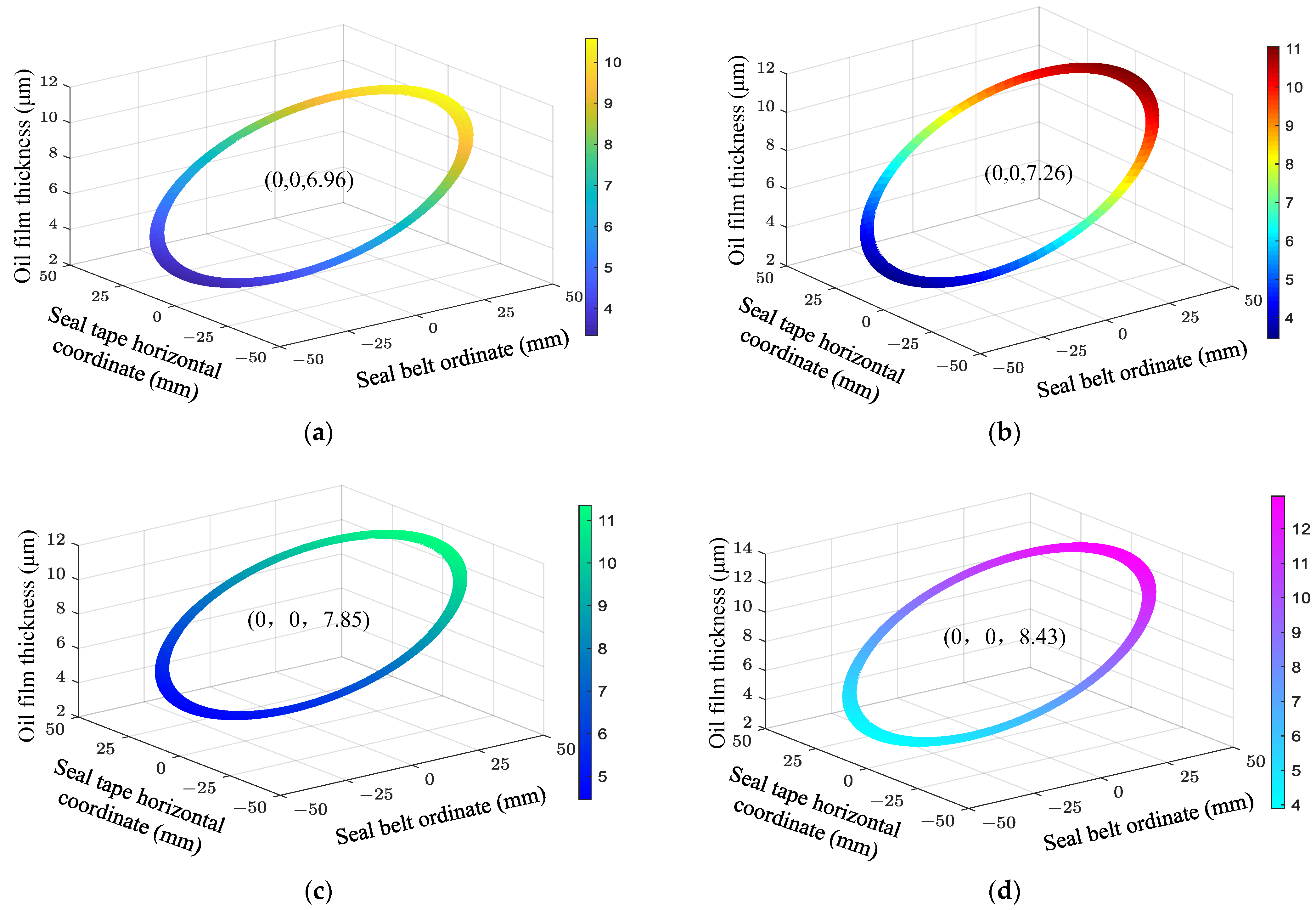
3.1. Effect of Rotational Speed on the Oil Film Thickness of the Slipper Pair

Figure 6 shows the impact of various rotational speeds on the oil film thickness of a slipper pair annular seal tape under 3 MPa and 35 °C conditions. According to a comparison of the oil film thickness of the annular seal tape of the slipper pair at various rotational speeds, the oil film thickness of the slipper pair increases with increasing rotating speed. The central oil film thickness of the slipper pair increases from 6.96 μm at 800 r/min to 8.43 μm at 1800 r/min. The faster the rotational speed, the greater the temperature rise caused by heat transfer between the swash plate and the slipper, resulting in a bigger oil film expansion height due to the thermal wedge effect. Therefore, as the rotational speed increases, the oil film thickness of the slipper pair gradually increases. Secondly, as the rotational speed increases, the overturning amplitude of the oil film on the bottom surface of the slipper pair gradually increases. The faster the rotational speed, the bigger the speed differential between the slipper’s bottom surface and the swash plate center’s inner and outer side lines, and the larger the overturning amplitude of the oil film on the bottom surface of the slipper pair, resulting in a gradual increase in the deflection degree of the slipper.
Figure 7 illustrates the effect of varying rotational speeds on oil film thickness of slipper pair bottom surface at 3 MPa and 35 °C. The figure shows that the difference between the highest and lowest oil film thickness of the slipper pair presents a trend of gradual increase, and the tilt angle of the slipper pair gradually increases. The difference between the highest and lowest oil film thickness of the slipper pair increases from 13.54 μm at 800 r/min to 16.80 μm at 1800 r/min. The tilt angle of the slipper pair is increased from 0.01197° to 0.01484°.

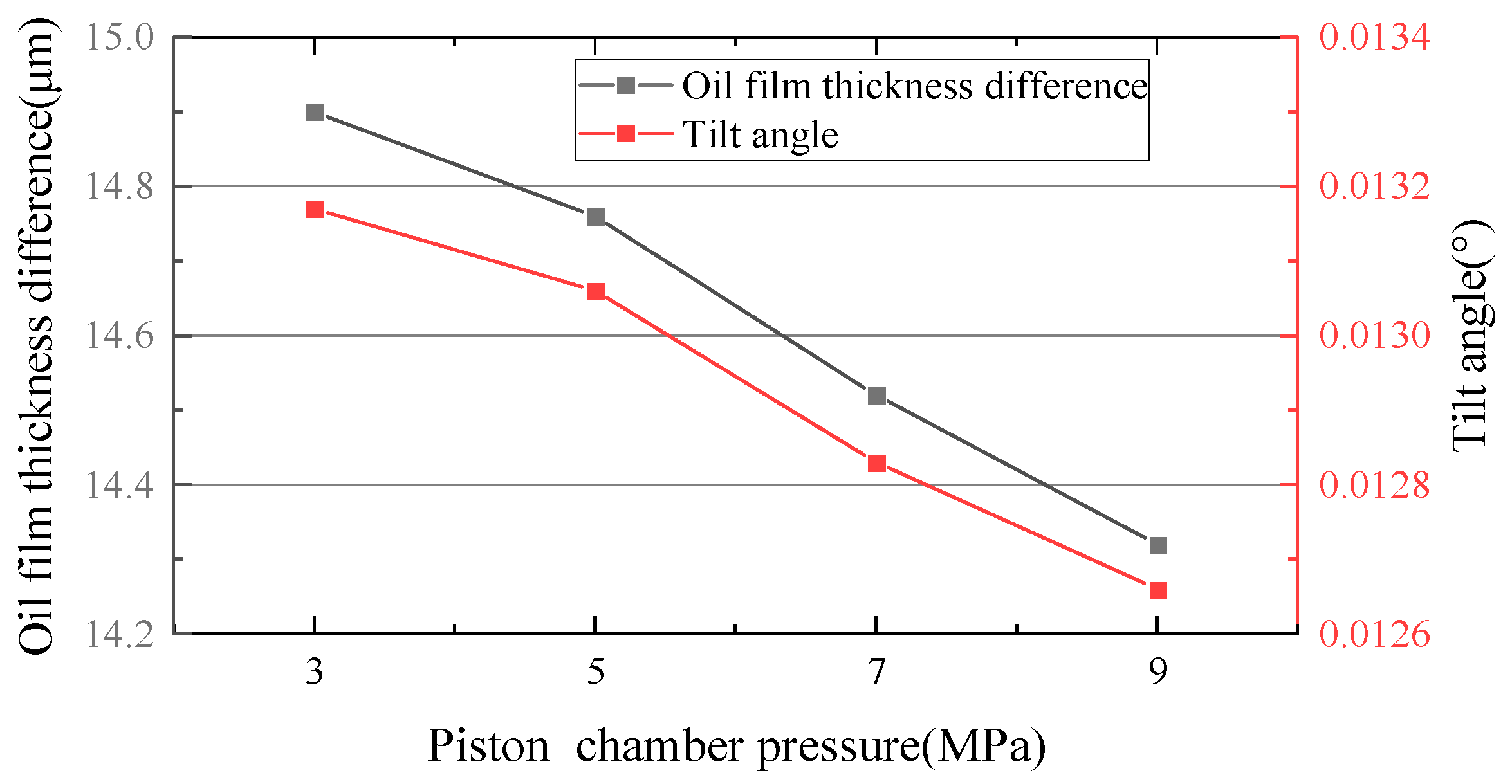
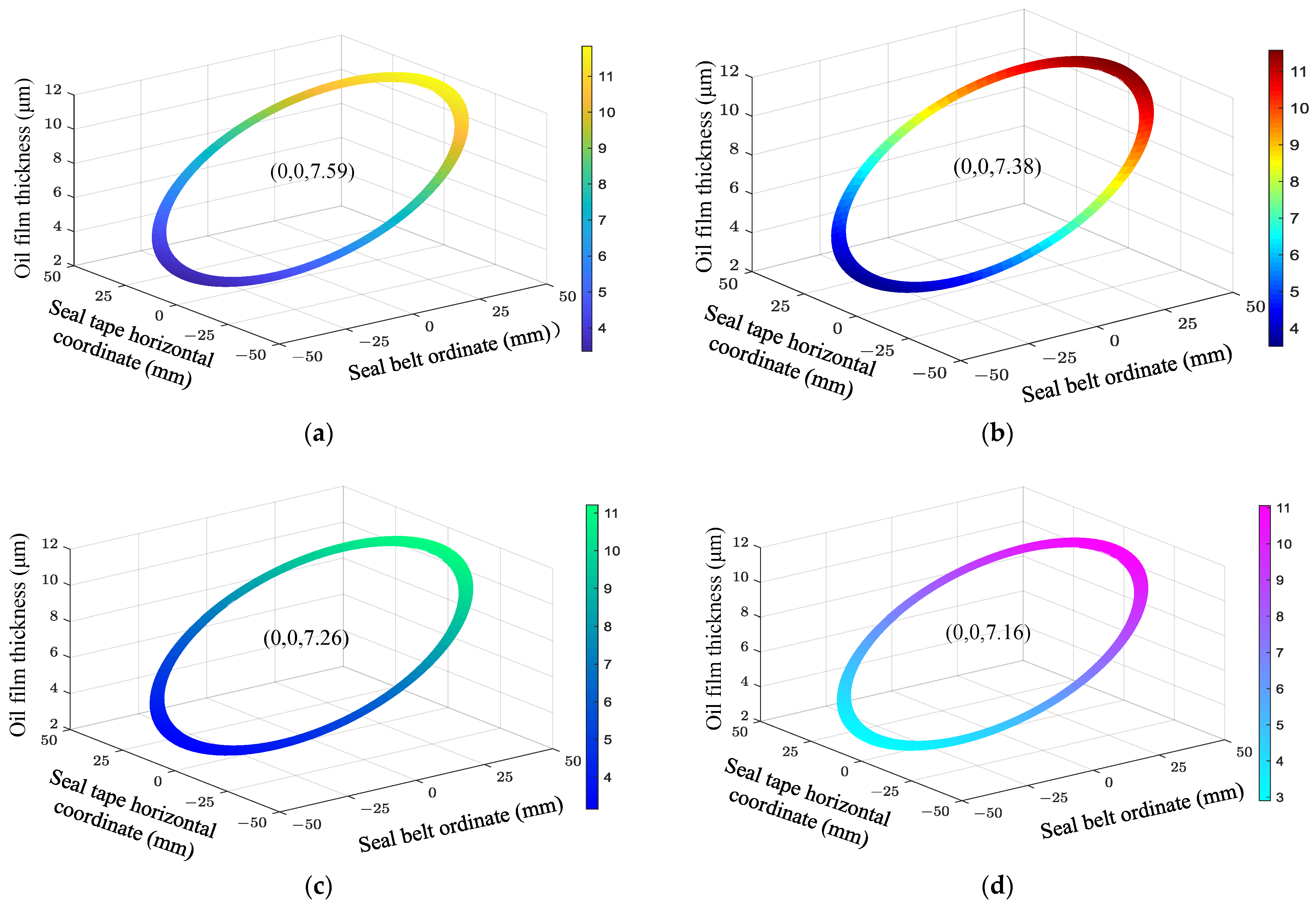
3.2. Effect of Piston Chamber Pressure on the Oil Film Thickness of the Slipper Pair

Figure 8 shows the impact of varied piston chamber pressures on the oil film thickness of the slipper pair at 1200 r/min and 35 °C. The oil film thickness of the slipper pair will decrease as piston chamber pressure increases, based on a comparison of the annular seal tape oil film thickness diagram under various piston chamber pressure conditions. The central oil film thickness of the slipper pair decreases from 7.54 μm at 3 MPa to 7.16 μm at 9 MPa. The reason is that the pressure of the closed oil chamber in the slipper is the main aspect of power loss, which is inversely proportional to the third power of the oil film thickness. Under the action of pressure, the oil film thickness of the slipper pair decreases with the increase of the extrusion bearing effect. Secondly, as the pressure of the piston chamber rises, the overturning amplitude of the oil film on the bottom surface of the slipper pair gradually decreases. This is because, compared with the outer side of the swash plate, the linear speed of the slipper is larger, which causes the oil film temperature to rise more greatly during the movement. Meanwhile, the heat transfer rate between the slipper and the swash plate increases with the gradual rise of the oil film temperature, and the deformation degree between the slipper and the swash plate increases the compression degree of the outermost oil film thickness of the slipper, so the overturning amplitude of the oil film on the bottom of the slipper is gradually reduced.
Figure 9 shows the impact of various piston chamber pressures on oil film thickness of a slipper pair at 1200 r/min and 35 °C. The figure shows that the difference between the highest and lowest oil film thickness of the slipper pair showed a decreasing trend, and the tilt angle of the slipper pair gradually decreased. The difference between the highest and lowest oil film thickness of the slipper pair decreases from 14.90 μm at 3 MPa to 14.32 μm at 9 MPa. The tilt angle of the slipper pair is reduced from 0.01317° to 0.01266°.

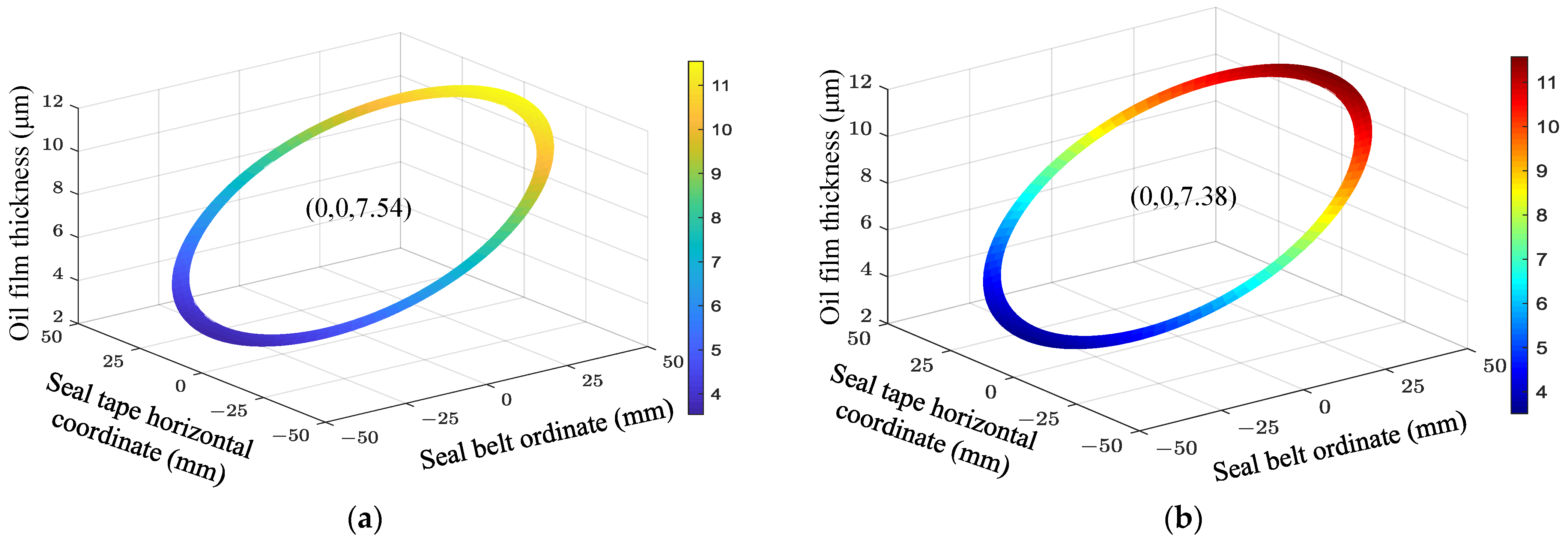
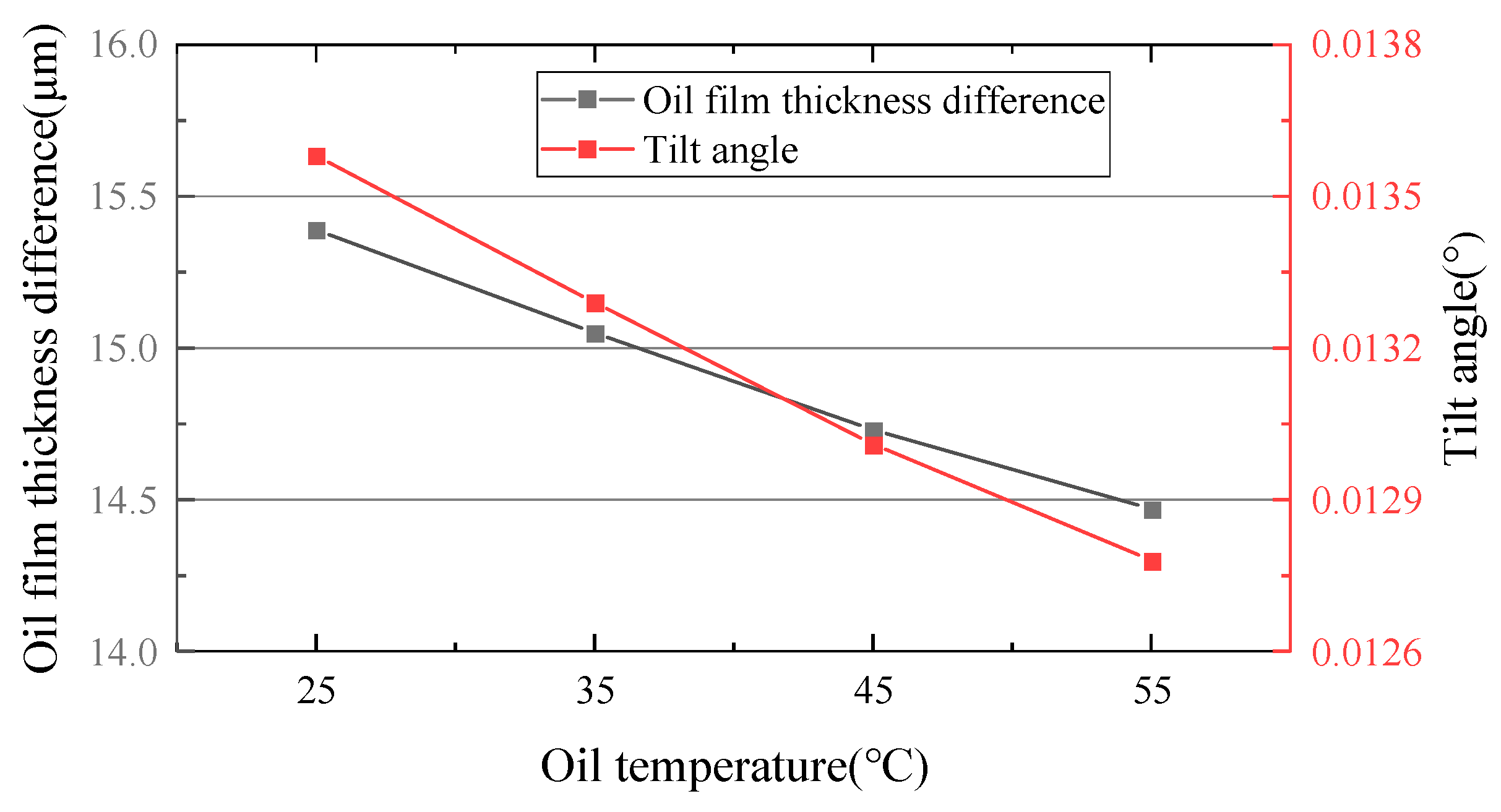
3.3. Effect of Oil Temperature on the Oil Film Thickness of the Slipper Pair

Figure 10 illustrates the impact of varying oil temperatures on the oil film thickness of the slipper pair at 5 MPa and 1200 r/min. According to a comparison of the oil film thickness of the annular seal tape of the slipper pair at different oil temperatures, the oil film thickness of the slipper pair will decrease as the oil temperature increases. The central oil film thickness of the slipper pair will decrease from 7.59 μm at 25 °C to 7.01 μm at 55 °C. The reason is that the oil temperature affects the heat conduction effect of the oil film of the slipper pair. In addition, the heat accumulation value of the oil film of the slipper pair is proportional to the temperature of the oil. As the oil temperature increases, the internal energy of the oil film increases, and the convective exchange among the slipper, swash plate, and oil film is enhanced. As a result, the surface temperature of the slipper and the swash plate rises, the expansion and deformation of the slipper and the swash plate themselves increase, and the gap between the slipper and the swash plate is compressed. The thickness of the oil film formed between the two is reduced. Secondly, as the oil temperature increases, the overturning amplitude of oil film on the bottom surface of the slipper pair gradually decreases. This is because with increase in oil temperature, the temperature of the outer edge of the slipper pair rises faster, making the gap between slipper and swash plate smaller, so the oil film thickness is reduced more, making the overturning effect of the slipper gradually reduced.
Figure 11 demonstrates the impact of different oil temperatures on oil film thickness of the slipper pair at 1200 r/min and 5 MPa. The figure shows that the difference between the highest and lowest oil film thickness of the slipper pair gradually decreases, and the tilt angle of the slipper pair gradually decreases. The difference between the highest and lowest oil film thickness of the slipper pair decreases from 15.39 μm at 25 °C to 14.47 μm at 55 °C. The tilt angle of the slipper pair is reduced from 0.01358° to 0.01278°.

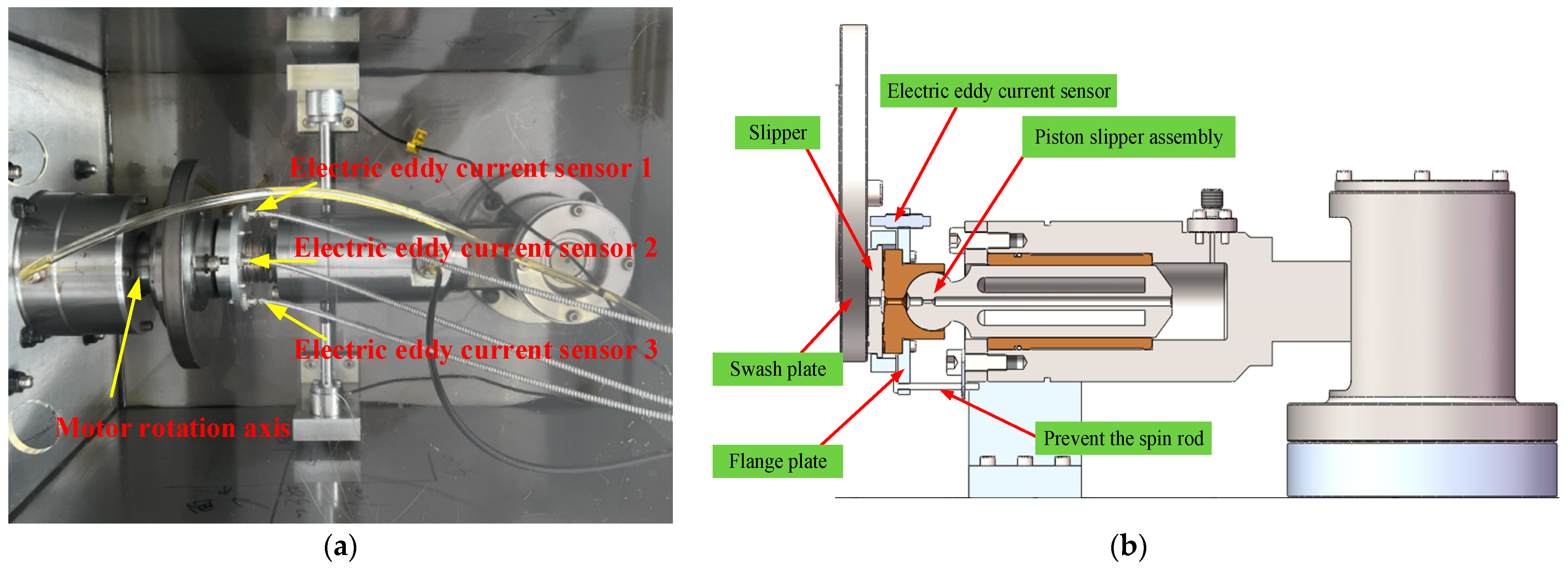
4. Experimental Contrastive Analysis

A test device is set up to measure the oil film thickness of the slipper pair to verify the theory of oil film thickness of the slipper pair of LDPP. Figure 12a shows the test device’s structural diagram. The variable frequency motor drives the swash plate sample to rotate to simulate the rotation of the cylinder block in the piston pump. The swash plate is in sliding contact with the surface of the slipper, and the slipper is attached to swash plate under the force of the spring to simulate the role of the return plate and the compression spring in the piston pump. In order to achieve the test purpose of measuring the oil film thickness of slipper pair in the LDPP, the hydraulic pump is connected at the bottom of the piston slipper assembly in the test device. The liquid pressure at the bottom of the piston is regulated through the throttle valve and the relief valve, and the variable frequency motor drives the rotation of the swash plate, simulating the motion of the slipper in the piston pump. Figure 12b illustrates the structural diagram of oil film thickness measurement. The oil film thickness measuring equipment consists primarily of an electric eddy current sensor, an acquisition card, and a computer.
Because the oil film on the slipper bottom has a ring structure, the thickness of oil film is estimated by taking three non-collinear spots on the slipper bottom surface. Due to the limitations of the test device itself, this paper selects three points on the most outer circle edge of the flange that are 90° of each other for representation. Figure 13 shows the calculation method for the oil film thickness of the slipper bottom.
In the XYZ space coordinate system, the oil film thickness of the three points selected on the bottom surface of slipper is measured by the electric eddy current sensor as ( h 1 , h 2 , h 3 ) , and it can be concluded that the points on the plane determined by these three points meet the following requirements:
x y r 6 z h 1 r 6 r 6 h 2 h 1 r 6 r 6 h 3 h 1 = 0
The plane equation is converted into polar coordinates, and the thickness of any point on the slipper surface in this coordinate system is:
h ( r , θ ) = 1 2 r 6 ( h 2 h 3 ) r cos θ   + 1 2 r 6 ( 2 h 1 h 2 h 3 ) r sin θ + 1 2 ( h 2 + h 3 )
In the test, the material of swash plate is 38 CrMoAlA, and the material of slipper is QAl9-4. The piston slipper assembly in the actual LDPP is used to fit the actual working state as much as possible. The oil used in this test is Kunlun HM-32 hydraulic oil, which has excellent thermal stability, oxidation resistance, and wear resistance. The electric eddy current sensor model is the ML33-01-10 displacement sensor, (Shenzhen Milang Technology Co., Ltd., Shenzhen, China) and the accuracy was 0.01 μm, which outputs the data to the computer for display and recording through the cable. Table 2 shows the key parameters of the electric eddy current displacement sensor.
To assure the accuracy of the test data, the oil film thickness in the test was measured three times, the average value was calculated, and the analysis of deviation was performed on them.

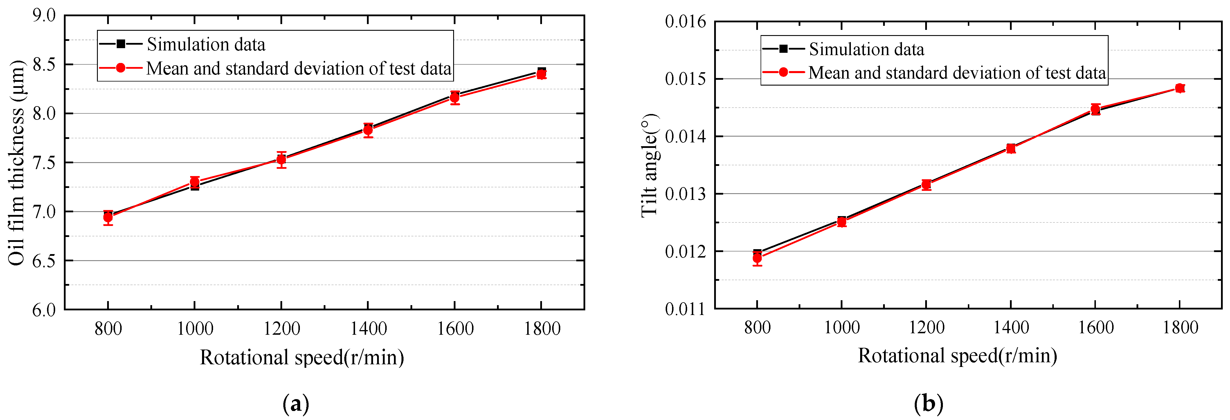
4.1. Comparison of the Effect of Rotational Speed

Figure 14 illustrates the test and simulation impacts of varying rotational speeds on the central oil film thickness of a slipper pair at 3 MPa and 35 °C. To assure the accuracy of the test data, t the oil film thickness in the test was measured three times, the average value was calculated, and the analysis of deviation was performed on them. The comparison between the test and simulated data that the curve of oil film thickness in the center of slipper pair shows the same trend as that of the simulation data, both of which increases as the rotational speed increases. This is consistent with the experimental trend shown in reference [24,28]. Due to different working conditions, the specific oil film thickness in this study is different from that in reference [24,28]. When the rotation speed is 1200 r/min, the maximum error is 0.04 μm, and the percentage of error is 0.55%. The trend of the test data curve of the tilt angle of the slipper is the same as that of the simulation data curve, which increases as the rotational speed increases, and the increase of the tilt angle decreases gradually with the increase in speed.

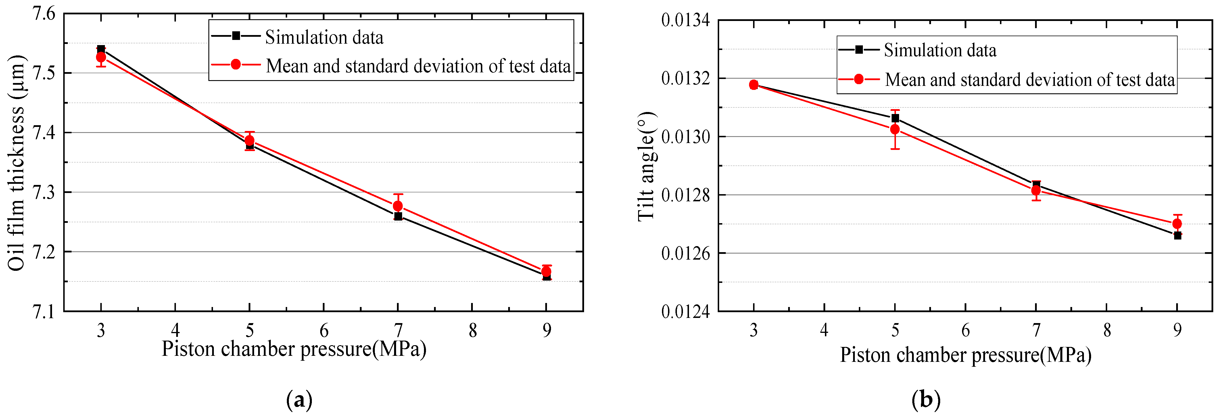
4.2. Comparison of the Effect of Piston Chamber Pressure

Figure 15 shows the test and simulation impacts of varying piston chamber pressures on the oil film thickness of the slipper pair at 1200 r/min and 35 °C. The comparison between the test data and the simulated data shows that the curve of oil film thickness in the center of the slipper pair has the same trend as the curve of the simulation data, and both decrease as the pressure of the piston chamber increases. This is consistent with the experimental trend shown in reference [24,28]. Due to different working conditions, the specific oil film thickness in this study is different from that in reference [24,28]. When the pressure is 7 MPa, the maximum error is 0.02 μm, and the percentage of error is 0.28%. The trend of the curve of the test data and the simulation data is the same; both decreased as pressure increased, and the decrease of the tilt angle gradually slows down as pressure increases.

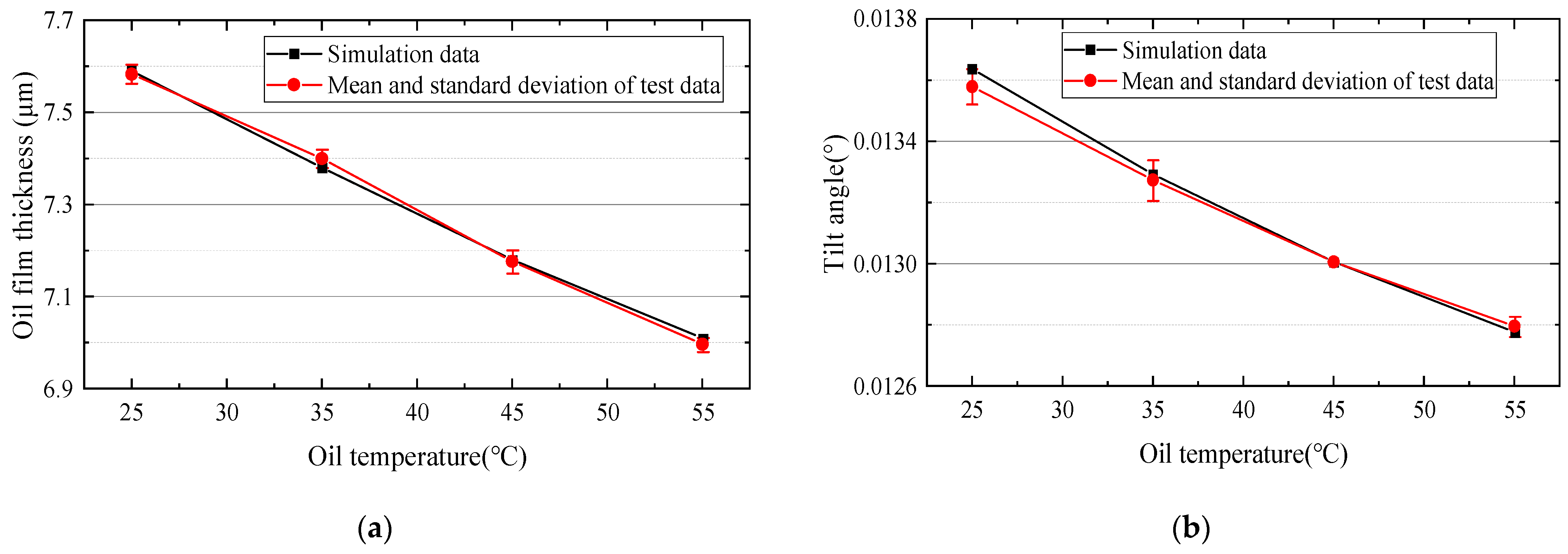
4.3. Comparison of Effects of Oil Temperature

Figure 16 shows the test and simulation effects of different oil temperatures on the oil film thickness in the center of the slipper pair at 1200 r/min and 5 MPa. The comparison between the test data and the simulated data that the curve of the oil film thickness in the center of the slipper pair has the same trend as the curve of the simulation data, they all decrease as the temperature rises. This is consistent with the experimental trend shown in reference [29]. Due to different working conditions, the specific oil film thickness in this study is different from that in reference [29]. When the oil temperature is 55 °C, the maximum error is 0.03 μm, and the percentage error is 0.43%. The trend of the curve of the test data and the simulation data is the same; both decreased as oil temperature increased, and with the continuous rise of the oil temperature, the decrease of the tilt angle gradually slows down.
It can be seen from the above three comparative tests that the experimental data are different from the simulation results. This is because the heat conduction of the oil takes a certain time in the actual test. Under the conditions of rotational speed, piston chamber pressure, and oil temperature rise, the temperature rise and heat conduction time also change to a certain extent. Therefore, the length of the interval time in the test of the oil film thickness of the slipper pair under different conditions will have a certain impact on the test data.

5. Conclusions

In this work, the oil film lubrication characteristics of a LDPP slipper pair under various working situations are examined. The following are the primary conclusions that can be made from the study:
(1) In this paper, a research method for the oil film thickness of the slipper pair of the LDPP under the condition of residual compression force is proposed. The oil film thickness model of the slipper pair of the LDPP is obtained by introducing the heat transfer relationship into the force analysis of slipper pair on the basis of considering linear velocity difference between the inner and outer positions of slipper pair relative to swash plate center during high-speed rotation.
(2) The large size of the bottom surface of the slipper pair of the LDPP leads to the obvious difference in the linear velocity of the slipper surface, and the different linear velocity causes the different heat generated by the oil film, which causes the tilt of the slipper. The tilt angle of slipper pair is proportional to the rotational speed and inversely proportional to the piston chamber pressure and oil temperature.
(3) As the rotational speed increases, the thickness of the oil film in the center and tilt angle of the slipper pair of LDPP increases gradually. As the piston chamber pressure and oil temperature increases, the thickness of the oil film in the center and tilt angle of the slipper pair of LDPP decreases gradually.
(4) This paper provides some theoretical support for the development of the main components of the LDPP by showing the variation law of the oil film thickness and tilt angle of the slipper pair of LDPP under the interaction of speed, pressure, and temperature through a combination of simulation and experiment.

Author Contributions

Methodology and writing—original draft preparation, L.X. and J.C.; test and data processing, D.L. and L.Z.; project administration, Y.J.; checking and supervision, F.G. and J.L. All authors have read and agreed to the published version of the manuscript.

Funding

This research was funded by the National Natural Science Foundation of China, grant number 52105054, Key scientific and technological projects in Henan Province, grant numbers 222102220012 and 222102220073, and Key scientific research projects of colleges and universities in Henan Province, 22A460004 and 22A460017.

Data Availability Statement

The data supported results are included within this article.

Conflicts of Interest

The authors declare no conflict of interest.

References

  1. Wu, H.; Zhao, L.; Ni, S.; He, Y. Study on friction performance and mechanism of slipper pair under different paired materials in high-pressure axial piston pump. Friction 2020, 8, 957–969. [Google Scholar] [CrossRef]
  2. Chao, Q.; Zhang, J.; Xu, B.; Wang, Q.; Lyu, F.; Li, K. Integrated slipper retainer mechanism to eliminate slipper wear in high-speed axial piston pumps. Front. Mech. Eng. 2022, 17, 1. [Google Scholar] [CrossRef]
  3. Zhang, X.; Wu, H.; Chen, C.; Wang, D.; Li, S. Oil film lubrication state analysis of piston pair in piston pump based on coupling characteristics of the fluid thermal structure. Eng. Fail. Anal. 2022, 140, 106521. [Google Scholar] [CrossRef]
  4. Yin, F.; Chen, Y.; Ma, Z.; Nie, S.; Ji, H. Investigation on mixed thermalelstohydrodynamic lubrication behavior of slipper/swash plate interface in water hydraulic axial piston pump. Tribol. Int. 2023, 189, 108896. [Google Scholar] [CrossRef]
  5. Wu, J.; Ma, L.; An, G.; Han, H. Squeeze Film Effect and Its Influence on the Lubrication Characteristics of Slipper Oil Film under Pressure Pulse. Shock Vib. 2023, 2023, 2731176. [Google Scholar] [CrossRef]
  6. Liu, S.; Li, Z.; Sun, W.; Ai, C.; Zhang, W.; Zhang, Y.; Chen, Z. A Mixed Lubrication Model for Predicting the Lubrication Performance Degradation Behavior of Slipper Pair in Early Wear Failure. IEEE Access 2023, 11, 100479–100494. [Google Scholar] [CrossRef]
  7. Wang, H.; Shi, G. Lubrication characteristics of the worn slipper in the slipper-swashplate pair. Ind. Lubr. Tribo 2021, 73, 1037–1044. [Google Scholar] [CrossRef]
  8. Hashemi, S.; Friedrich, H.; Bobach, L.; Bartel, D. Validation of a thermal elastohydrodynamic multibody dynamics model of the slipper pad by friction force measurement in the axial piston pump. Tribol. Int. 2017, 115, 319–337. [Google Scholar] [CrossRef]
  9. Xu, L.; Sun, H.; Xu, S. Fracture mechanism analysis on the slipper retainer in axial piston pumps. Eng. Fail. Anal. 2017, 80, 378–385. [Google Scholar] [CrossRef]
  10. Gaston, H.; Wang, D. Analysis of Damage and Failure mechanism under a lubricated slipper/swashplate interface in Axial Piston Machines. Sci. Direct 2022, 35, 124–131. [Google Scholar]
  11. Xu, B.; Li, Y.; Zhang, B.; Zhang, J. Numerical simulation of overturning phenomenon of axial piston pump slipper pair. J. Mech. Eng. 2010, 46, 161–168. [Google Scholar] [CrossRef]
  12. Xu, B.; Wang, Q.; Zhang, J. Effect of case drain pressure on slipper/swashplate pair within axial piston pump. J. Zhejiang Univ.-Sci. A 2015, 16, 1001–1014. [Google Scholar] [CrossRef]
  13. Mo, H.; Hu, Y.; Quan, S. Thermo-Hydrodynamic Lubrication Analysis of Slipper Pair Considering Wear Profile. Lubricants 2023, 11, 190. [Google Scholar] [CrossRef]
  14. Bergada, J.; Watton, J.; Haynes, J.M.; Davies, D.L. The hydrostatic/hydrodynamic behaviour of an axial piston pump slipper with multiple lands. Meccanica 2010, 45, 585–602. [Google Scholar] [CrossRef]
  15. Schenk, A.; Ivantysynova, M. A Transient Thermoelastohydrodynamic Lubrication Model for the Slipper/Swashplate in Axial Piston Machines. J. Tribol. 2015, 137, 031701. [Google Scholar] [CrossRef]
  16. Rokala, M.; Calonius, O.; Koskinen, K.T.; Pietola, M. Study of lubrication conditions in slipper-swashplate contact in water hydraulic axial piston pump test rig. In Proceedings of the JFPS International Symposium on Fluid Power; The Japan Fluid Power System Society: Tokyo, Japan, 2008; pp. 91–94. [Google Scholar]
  17. Tang, H.; Ren, Y.; Xiang, J. A novel model for predicting thermoelastohydrodynamic lubrication characteristics of slipper pair in axial piston pump. Int. J. Mech. Sci. 2017, 124, 109–121. [Google Scholar] [CrossRef]
  18. Tang, H.; Yin, Y.; Ren, Y.; Xiang, J.; Chen, J. Impact of the thermal effect on the load-carrying capacity of a slipper pair for an aviation axial-piston pump. Chin. J. Aeronaut. 2018, 31, 395–409. [Google Scholar] [CrossRef]
  19. Zhao, K.; He, T.; Wang, C.; Chen, Q.; Li, Z. Lubrication characteristics analysis of slipper pair of digital valve distribution axial piston pump. Adv. Mech. Eng. 2022, 14, 16878132221085442. [Google Scholar] [CrossRef]
  20. Jiang, J.; Wang, Z.; Li, G. The impact of slipper microstructure on slipper-swashplate lubrication interface in axial piston pump. IEEE Access 2020, 8, 222865–222875. [Google Scholar] [CrossRef]
  21. Jiang, J.; Wang, Z. Optimization and influence of micro-chamfering on oil film lubrication characteristics of slipper/swashplate interface within axial piston pump. Energies 2021, 14, 1961. [Google Scholar] [CrossRef]
  22. Song, Y.; Zeng, S.; Ma, J.; Hou, J. Failure analysis of graphite stationary ring utilized in one type of mechanical seal. Eng. Fail. Anal. 2020, 108, 104259. [Google Scholar] [CrossRef]
  23. Shi, C.; Wang, S.; Wang, X.; Zhang, Y. Variable load failure mechanism for high-speed load sensing electro-hydrostatic actuator pump of aircraft. Chin. J. Aeronaut. 2018, 31, 949–964. [Google Scholar] [CrossRef]
  24. Zhou, J.; Zhou, J.; Jing, C. Experimental research on the dynamic lubricating performance of slipper/swash plate interface in axial piston pumps. Chin. J. Mech. Eng. 2020, 33, 25. [Google Scholar] [CrossRef]
  25. Ma, J.; Chen, J.; Li, J.; Li, Q.; Ren, C. Wear analysis of swash plate/slipper pair of axis piston hydraulic pump. Tribol. Int. 2015, 90, 467–472. [Google Scholar] [CrossRef]
  26. Zhang, J.; Chao, Q.; Wang, Q.; Xu, B.; Chen, Y.; Li, Y. Experimental investigations of the slipper spin in an axial piston pump. Measurement 2017, 102, 112–120. [Google Scholar] [CrossRef]
  27. Zhang, J.; Xu, H.; Chen, J.; Huang, W.; Huang, X.; Lyu, F.; Xu, B.; Pan, M.; Su, Q. Modeling and Analysis of the tilt behavior of the cylinder block in a high-speed axial piston pump. Mech. Mach. Theory 2022, 170, 25. [Google Scholar]
  28. Shen, R.; Pan, Y. Friction characteristic analysis of slipper pair in A11VO190 axial piston pumps. Chin. J. Eng. Design 2014, 21, 51–55. [Google Scholar]
  29. Tang, H.; Yan, Y.; Li, J. Lubrication characteristics analysis of slipper bearing in axial piston pump considering thermal effect. Lubr. Sci. 2016, 28, 107–124. [Google Scholar]
  30. Yu, S. Characteristics Analysis and Structure Optimization of Slipper with Static and Dynamic Pressure Support Used in the Axial Piston Pump. Master’s Thesis, Harbin Institute of Technology, Harbin, China, July 2013. [Google Scholar]
  31. Sun, Y. Testing System Research for Investigating the Properties of Slipper Pair in High Speed and High Pressure Axial Piston Pump. Master’s Thesis, Zhejiang University, Hangzhou, China, March 2016. [Google Scholar]
  32. Xu, B.; Sun, Y.; Zhang, J.; Sun, T.; Mao, Z. A new design method for the transition region of the valve plate for an axial piston pump. J. Zhejiang Univ.-Sci. A 2015, 16, 229–240. [Google Scholar] [CrossRef]
  33. Tang, H.; Yan, Y.; Li, J.; Wang, Z. Thermohydrodynamic Lubrication Analysis of Slipper Pair in Axial Piston Pump Considering Surface Deformation. Chin. J. Mech. Eng. 2017, 53, 168–176. [Google Scholar] [CrossRef]
Figure 1. Diagram of the slipper bottom surface structure. 1—outside support ring; 2—annular oil groove; 3—Sealing ring; 4—inner support ring.
Lubricants 11 00521 g001
Figure 2. Force analysis diagram of slipper pair.
Lubricants 11 00521 g002
Figure 3. Hot wedge effect diagram of slipper motion in LDPP.
Lubricants 11 00521 g003
Figure 4. Heat transfer process of slipper pair.
Lubricants 11 00521 g004
Figure 5. Flow chart for solving the oil film thickness of slipper pair.
Lubricants 11 00521 g005
Figure 6. Simulation of oil film thickness of slipper pair with various rotational speeds (a) Speed 800 r/min; (b) Speed 1000 r/min; (c) Speed 1400 r/min; (d) Speed 1800 r/min.
Lubricants 11 00521 g006
Figure 7. Effect of rotational speed on oil film thickness of slipper pair.
Lubricants 11 00521 g007
Figure 8. Simulation of oil film thickness of slipper pair under various piston chamber pressures. (a) Piston chamber pressure is 3 MPa; (b) Piston chamber pressure is 5 MPa; (c) Piston chamber pressure is 7 MPa; (d) Piston chamber pressure is 9 MPa.
Lubricants 11 00521 g008aLubricants 11 00521 g008b
Figure 9. Effect of piston chamber pressure on the thickness of the oil film of slipper pair.
Lubricants 11 00521 g009
Figure 10. Simulation of oil film thickness of slipper pair under various oil temperatures. (a) Oil temperature 25 °C; (b) Oil temperature 35 °C; (c) Oil temperature 45 °C; (d) Oil temperature 55 °C.
Lubricants 11 00521 g010
Figure 11. Effect of oil temperature on oil film thickness of slipper pair.
Lubricants 11 00521 g011
Figure 12. Structure diagram. (a) Test device structure diagram (b) Oil film thickness measurement structure diagram.
Lubricants 11 00521 g012
Figure 13. LDPP slipper bottom surface oil film thickness calculation method.
Lubricants 11 00521 g013
Figure 14. Rotational speed on slipper pair oil film thickness test and simulation comparison (a) Oil film thickness slipper pair center; (b) Tilt angle.
Lubricants 11 00521 g014
Figure 15. Piston chamber pressure on slipper pair oil film thickness test and simulation comparison. (a) Oil film thickness slipper pair center; (b) Tilt angle.
Lubricants 11 00521 g015
Figure 16. Oil temperature on slipper pair oil film thickness test and simulation comparison (a) Oil film thickness slipper pair center; (b) Tilt angle.
Lubricants 11 00521 g016
Table 1. Simulation parameter setting of oil film thickness of slipper pair.
Correlation ParameterNumerical Value
Inner diameter of slipper auxiliary ring r 1 13.3 mm
Outer diameter of slipper inner auxiliary ring r 2 15.85 mm
Slipper seal with inner diameter r 3 20.05 mm
Slipper seal with outer diameter r 4 24.85 mm
Inside diameter of slipper outer auxiliary ring r 5 27.6 mm
Outer diameter of slipper auxiliary ring r 6 32.4 mm
Diameter of damping tube d 1 2 mm
Damping tube length l 6 mm
Piston distribution circle radius R 100 mm
Piston diameter D 45 mm
Quality of single piston assembly m 1.7 kg
Volume expansion coefficient of oil γ 0 0.7 × 10 3   ° C 1
The density of oil ρ 860 kg/m3
Specific heat capacity of oil c e 1.98   KJ / ( kg ° C )
Acceleration of gravity g 9.8 m/s2
Oil dynamic viscosity coefficient μ 1.97 × 10 2   Pa s
Thermal equivalent G 481.2 J
Precompression force F 2 30 N
Thermal conductivity k 1 92   W ( m ° C ) 1
Linear expansion coefficient of slipper α 1 16.2 × 10 6   ° C 1
Slipper material thickness H 1 11 mm
Linear expansion coefficient of swash plate α 2 13 × 10 6   ° C 1
Swash plate material thickness H 2 18 mm
Thermal conductivity k 2 54.6   W ( m ° C ) 1
Thermal conductivity k 0 0.6   W ( m ° C ) 1
Swash plate roughnessRa 0.8
Slipper roughnessRa 1.6
Swash plate inclination γ 0
Piston dip angle β 0
Half angle of the cone θ x 30
Dynamic viscosity of hydraulic oil 25 °C85 mm2/s
Dynamic viscosity of hydraulic oil 35 °C50 mm2/s
Dynamic viscosity of hydraulic oil 45 °C40 mm2/s
Dynamic viscosity of hydraulic oil 55 °C25 mm2/s
Table 2. Electric eddy current displacement sensor main parameters table.
RangeCombined ErrorPrecisionOperating Temperature
0–1 mm ± 0.25 % F S 0.01 μm 30 ~ + 150   ° C
Disclaimer/Publisher’s Note: The statements, opinions and data contained in all publications are solely those of the individual author(s) and contributor(s) and not of MDPI and/or the editor(s). MDPI and/or the editor(s) disclaim responsibility for any injury to people or property resulting from any ideas, methods, instructions or products referred to in the content.

