Article

Sources and Destinations of Oil Leakage through TPOCR Based on 2D-LIF Observation and Modeling Analysis

Department of Mechanical Engineering, Massachusetts Institute of Technology, 77 Massachusetts Ave, Cambridge, MA 02139, USA
*
Author to whom correspondence should be addressed.
Lubricants 2023, 11(12), 522; https://doi.org/10.3390/lubricants11120522
Submission received: 2 November 2023 / Revised: 2 December 2023 / Accepted: 6 December 2023 / Published: 9 December 2023

Abstract

:
The Three-Piece Oil Control Ring (TPOCR) is becoming a viable option for heavy duty gas and hydrogen engines due to the low particle concentration in these engines. Although direct oil leakage from the gap is not likely to happen with the misalignment of the upper and lower rail gaps, there exist other less-apparent oil leaking mechanisms through the TPOCR. This work is targeted at understanding the oil leakage’s source and destination through the rail and liner interfaces across the whole cycle. The 2D Laser Induced Fluorescence technique was applied on an optical engine to study the oil transport behavior. Combined with a TPOCR model for dynamics and lubrication, the mechanisms that cause rail twist and oil scraping by the upper rail were analyzed. It was found that the symmetrical rail can scrape the oil up in the up-strokes. The scraped oil first accumulates in the clearance between the upper rail and groove, as well as at the upper corner of the rail Outer Diameter before being transferred to both the third land and liner when the piston changes direction at Top Dead Center. Rails with an asymmetrical profile can reduce or enhance these effects depending the orientation of the rails. This study provides findings that could help design the engine to better control Lubricate Oil Consumption and properly lubricate the Top Dead Center’s dry region at the same time.

1. Introduction

Internal combustion engines have been used widely in all aspects of transportation. The piston and ring pack are a very important component inside that transfers the chemical energy released from combustion into mechanical energy output. Specifically, the piston rings are used to seal the interface between the piston and liner, separating the high temperature and pressure combustion chamber from the crankcase. The ring pack works under extreme conditions that need enough lubrication to protect the running interface and reduce friction. Typically, 40–55% of the total mechanical loss is coming from the friction between the ring pack and liner [1]. A failure of the rings can cause engine power loss and even structural damage [2]. When the piston reaches the Top Dead Center (TDC) position, the top ring experiences the most severe working conditions for the high pressure, high temperature, frequent acceleration, and deacceleration [3] that requires protection from oil. However, on the other hand, too much excessive Lubricate Oil Consumption (LOC) could also be a problem. The metal additive in the lubricant can lead to a large amount of particulate emission [4,5], which is known as a major contributor to smog or haze weathers [6]. In addition, the oil consumption can accumulate ash in the Gasoline Particulate Filter (GPF) or Diesel Particulate Filter (DPF) [7], which can be installed on the aftertreatment system to capture the particles, and cause the engine power loss or knock [8]. Overall, it is critical to design the ring pack to balance the lubrication demand and consumption of oil. Thus, a thorough understanding of the oil transport mechanism in the ring pack is needed.
Specifically, the Oil Control Ring (OCR) is usually located at the bottom of the piston land, and its main function is to prevent the vast amount of oil in the skirt region from going up. The Three-Piece Oil Control Ring (TPOCR) is becoming a popular design for the misalignment of the rail gaps that largely reduce oil leakage. With the trend to use gas fuel (natural gas, hydrogen and ammonia) in heavy duty and large bore engines, TPOCR becomes more vital since it can reduce the abnormal combustion induced by oil [9]. It is critical to understand the source and path of oil transport through the TPOCR assembly.
Previous studies in [10] found that the TPOCR design will fail if the engine is running under a negative blowby condition, resulting in a vast amount of oil leakage through the upper rail gap. But a high value of LOC can still be measured at high engine loads [11,12], indicating that there exist other mechanisms to leak oil from the TPOCR. Tian built a TPOCR model [13] to integrate the rail, liner, and groove interactions, which provides the ability to simulate the ring dynamics. It was found that the rails can lose the sealing function for a short period of time when the sudden change of inertia force happens. This TPOCR model was further developed by Li [14], who added several detailed factors that could affect the lubrication of the TPOCR. Specifically, the profile of the two rails has a parabolic worn region in the middle and an unworn circular region on the side. The circular profile region has a significant contribution to friction and hydrodynamic pressure generation. Based on that, Zhang [15] further developed this model and identified an oil scraping behavior in the circular profile region.
In addition, the oil can leak through the TPOCR not only from the rail and liner interface. Studies in [16] combined the experimental observation and modeling calculation, which found that oil pumping can pass through the TPOCR under extreme conditions at a high speed and low load. It provides a path for oil upwards transport through the ring groove interface. Furthermore, studies in [17] measured the pressure under TPOCR through an experimental approach and found that an increased oil pressure under the TPOCR can lead to a higher oil consumption. Based on that, additional work in [18,19,20] analyzed the factors to reduce oil pressure under the TPOCR and pointed out a proper design of drain holes is needed.
Even though the previous works provided the understanding of different oil paths to leak out from TPOCR, an overall picture is still missing. This work is based on the scraping behavior identified in [15] and concluded an oil up-scraping leakage path at the TDC of both the intake and expansion stroke. An optical engine with a transparent sapphire window was used to observe the oil transport in the ring pack, especially around the TDC. Both the symmetrical rail profile, which is a common design, and an asymmetrical rail profile were tested to justify the up-scraping behavior. It provides both a major contribution to LOC and a necessary oil source to protect the dry region [21] at the same time.
In the following, the experimental equipment used in this study will be introduced first. Then, the primary observation of this oil up-scraping leakage will be presented and analyzed with the help of models. An explanation of this phenomenon regarding the upper and lower rail twist across the full engine cycle will be discussed. Lastly, different engine working conditions were tested to compare the oil up-scraping’s dependency with speed and load.

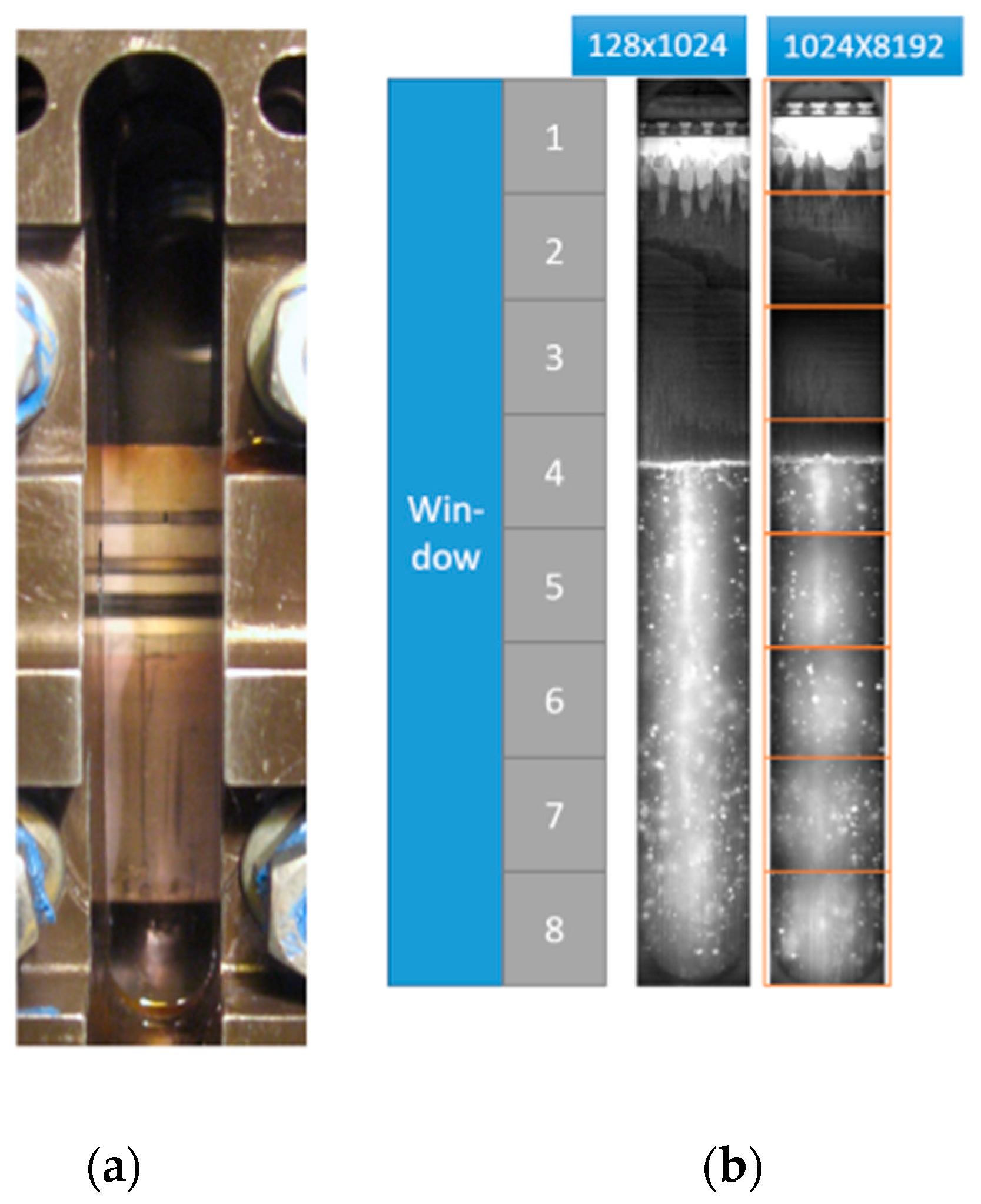
2. Experimental Setup
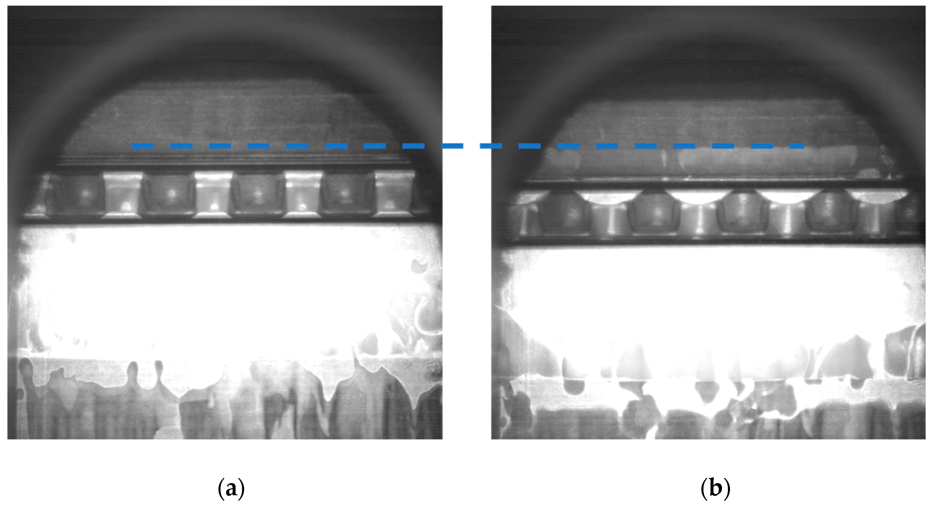
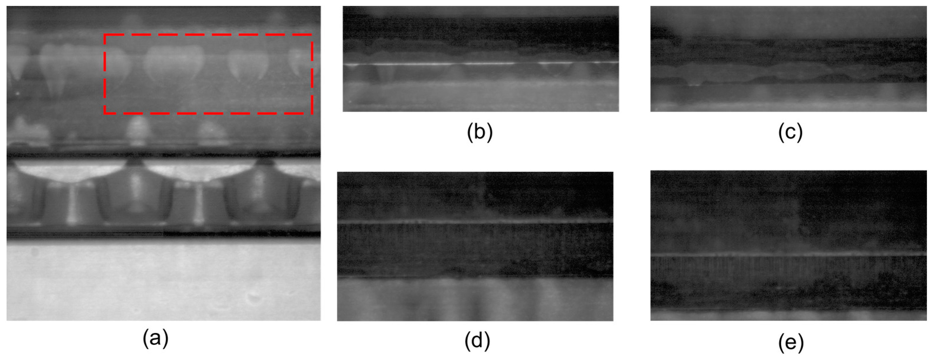
A prototype single-cylinder optical engine was applied to study the oil transport in the ring pack. This is the same engine as that used in previous studies [10]. It is a gasoline single-cylinder engine with a custom-made optical liner. Figure 1 shows the overall configuration of the engine, camera, and lens for the laser. The optical window was made of sapphire for its similarity in thermal expansion coefficient with cast iron, the material to make the rest of liner. It can provide a good sealing under fired conditions. The window can be either on a thrust or anti-thrust side. The size of window is 12 mm in width and 98.5 mm in length, allowing the observation range from the Top Dead Center (TDC) of the OCR to the Bottom Dead Center (BDC) of all three rings. Specifically, the top ring has a barrel shape profile with a positive twist. The second ring has a Napier hook chamfer on the ring-liner interface to store the scraped down oil. Two types of the low tension TPOCR were tested with a symmetrical and asymmetrical Outer Diameter (OD) profile shape on the rails. The profile can be divided into a relatively flat parabolic worn region in the middle and circular unworn region on the side. The symmetrical design is a common approach that the rail’s vertex or contact point of the flat parabolic profile is in the middle of the rail thickness. On the asymmetrical design, the contact point was shifted below the middle point. All three piston rings are free to rotate during the experiments. It can represent a typical ring pack for a light duty gasoline engine or a heavy duty gas fueled engine, such as a natural gas, hydrogen, and ammonia engine. An overall configuration of the piston and ring pack is shown in Table 1.
The 2D Laser Induced Fluorescence (2D-LIF) technique was applied on this prototype engine. The 0W-20 oil used in the experiment was mixed with a specific dye which can be induced to fluorescence by laser. A SA-X2 high speed camera was used to record video with the frame rate synchronized with a laser pulse. A brighter region in the camera view means a thicker oil film thickness and vice versa. In this study, the high-speed camera control was applied to record at 12,500 fps and 1/100,000 s shutter speed, converting to around 1 frame per crank angle at 2000 rpm. Under this setup, the highest resolution that can be achieved is 1024 × 1024 pixels focusing on a 12 mm × 12 mm square window (Figure 2). Thus, by adjusting the camera position, the full window can be divided into eight different squares and allows the observation at different crank angles. Furthermore, a double magnification view was developed with the same 1024 × 1024 resolution focusing on a 6 mm × 6 mm square area. It provides a better ability to observe oil transport inside ring grooves.
Engine tests were conducted at 1200 rpm, 2000 rpm, and 3000 rpm fired steady state conditions. The engine load was defined by adjusting the absolute intake pressure, ranging from 300 mbar to 700 mbar under fired condition. A NI-cDAQ system was applied to record the engine running data such as cylinder pressure, intake pressure, and air-fuel ratio. The recoding of data and optical video were synchronized through a field-programmable gate array (FPGA) system, including both hardware and software from National Instrument, USA, 2016. This allows for the recorded video to be stored with a real time engine running measurement data. A detailed description of the engine’s data recording and control system can be found in [22].

3. Results

Figure 3 shows the observation around the TDC in intake stroke at 3000 rpm 700 mbar fired condition. The engine was equipped with a TPOCR with the symmetrical rail profile. The profile has a parabolic shape with the vertex centered the middle. The upper and lower rails are the same and assembled with the gaps located 180 degrees separate from each other. Figure 3a shows the late exhaust stroke, 5CA BTDC. It can be observed as a bright line formed at the profile of TPOCR’s upper rail OD, indicating an increased oil film thickness there. The blue-dashed line marks the location of the upper rail’s TDC as well as the starting point of oil leakage. Due to the friction between the liner and rails pointing downwards, the TPOCR stayed at the bottom of the OCR groove in the up-stroke. The piston’s moving direction changed immediately as it reached the TDC. But the TPOCR stayed stationary until the piston’s down movement closed the clearance between the upper rail and groove (due to the friction force). Then the oil leakage to both piston land and liner can be observed in Figure 3b as the piston further moves down.
Specifically, the oil leakage can be divided into two sources. Figure 4 shows a LIF image with a section view demonstration. Source 1 is from the oil accumulated inside the groove. As the down movement of the piston squeezed these amounts of oil out, it can be further divided into two paths based on how far the oil travels. Path 1.1 represents the oil attached on the piston land. It can be observed that these oil puddles move down together with the piston. If the oil travels far enough to hit the liner, it becomes path 1.2 and goes to the liner. In this observation, the oil puddles from the 1.2 stick on the liner and does not move down with the piston. In addition, the oil source 2 is the oil carried by the upper rail profile. When the upper rail moves down, these amounts of oil can go to the liner through a reattachment process [23] and leave a thick oil film through path 2. This oil transfer from the upper rail/piston/liner interface to the liner at the TDC is for the first time identified. It can be a main oil leakage process by the TPOCR when the blowby is above zero, as net oil leakage from the upper rail gap can be eliminated [10]. The top two rings will be able to interact with this additional oil and transfer some of it to the dry region.
After the second ring moves to the TDC of TPOCR, where the oil leakage to liner happened, it can be observed that the oil leakage to the liner through path 1.2 and path 2 can both be partly scraped down by the second ring. Still, the increased oil film thickness on liner can enter and lubricate the top ring and liner interface as shown in Figure 5. The rest of oil can become a great contribution to LOC.
In the ensuing compression stroke when the piston moves back to the TDC again, the increased pressure in the combustion chamber can enter the top ring groove and push the ring against the liner, equivalent to an increased tension. The top ring can spread the thick oil film left on liner upwards and carry it in the barrel shape profile potentially to the TDC. It was identified by the previous modeling study in [24] and for the first time verified through experimental observation in Figure 6. This is an important mechanism to lubricate the ‘dry region’ at locations far away from the top ring gap [21]. Proper amount of this leakage by the TPOCR is critical to protecting the liner and top two rings as well as limiting the LOC to satisfactory level. A more in-depth study of the interaction of this oil leakage on the liner with the top two rings will be a subject of future publications.
In comparison, at the beginning of expansion stroke after the TDC, only oil leakage path 2, the oil carried by the upper rail profile and its reattachment to the liner, can be observed (Figure 7a). Figure 7b shows a comparison at the location of the 5CA BTDC in both the exhaust stroke (left) and compression stroke (right). Even though in the compression stroke there is also a bright line on the upper rail profile, the brightness is weaker compared to exhaust stroke. It indicates a reduced oil film thickness. Furthermore, no oil squeezed out from the OCR groove can be observed. It can be assumed as the amount of oil leakage at expansion stroke is less than that of intake stroke. The mechanisms and causes of this will be discussed in chapter 4.
The procedure states above can be concluded as the oil leakage due to the TPOCR’s up-scraping mechanism. The oil source comes mainly from the liner and scraped up by the TPOCR’s upper rail. It is an important mechanism to introduce LOC and lubricate the ‘dry region’ at the same time.

4. Discussion

The up-scraping mechanism mainly comes from the dynamics and lubrication of the TPOCR. A TPOCR model developed by Zhang [15] was applied to quantify the ring dynamic behaviors. It needs both geometry and piston land pressure boundary conditions as the input. The pressure in the piston lands can be calculated by feeding the real time engine running data into the 2D ring dynamic model, developed by Tian [24]. The geometry data of the TPOCR and ring groove was obtained from the drawings provided by the manufactures.

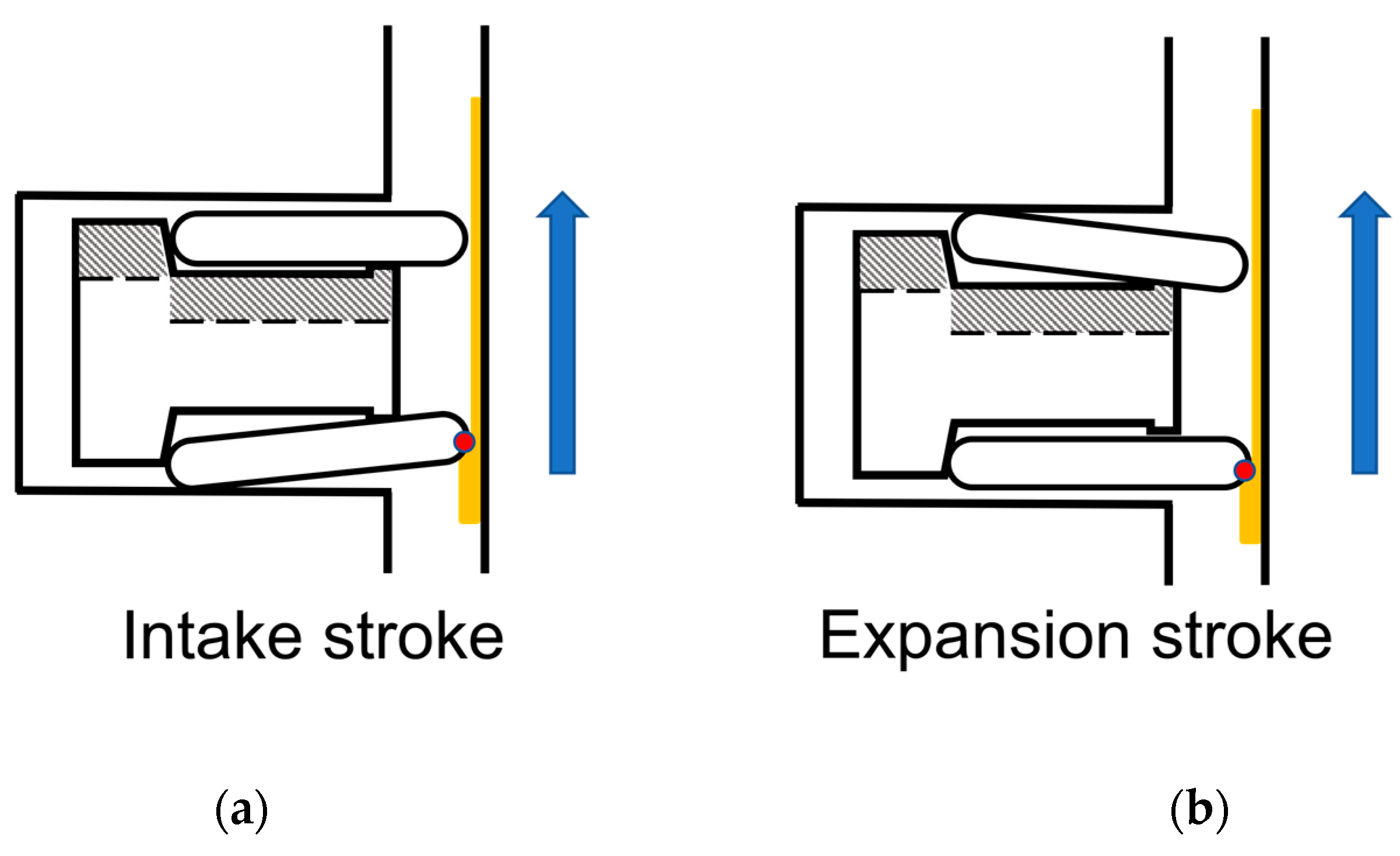
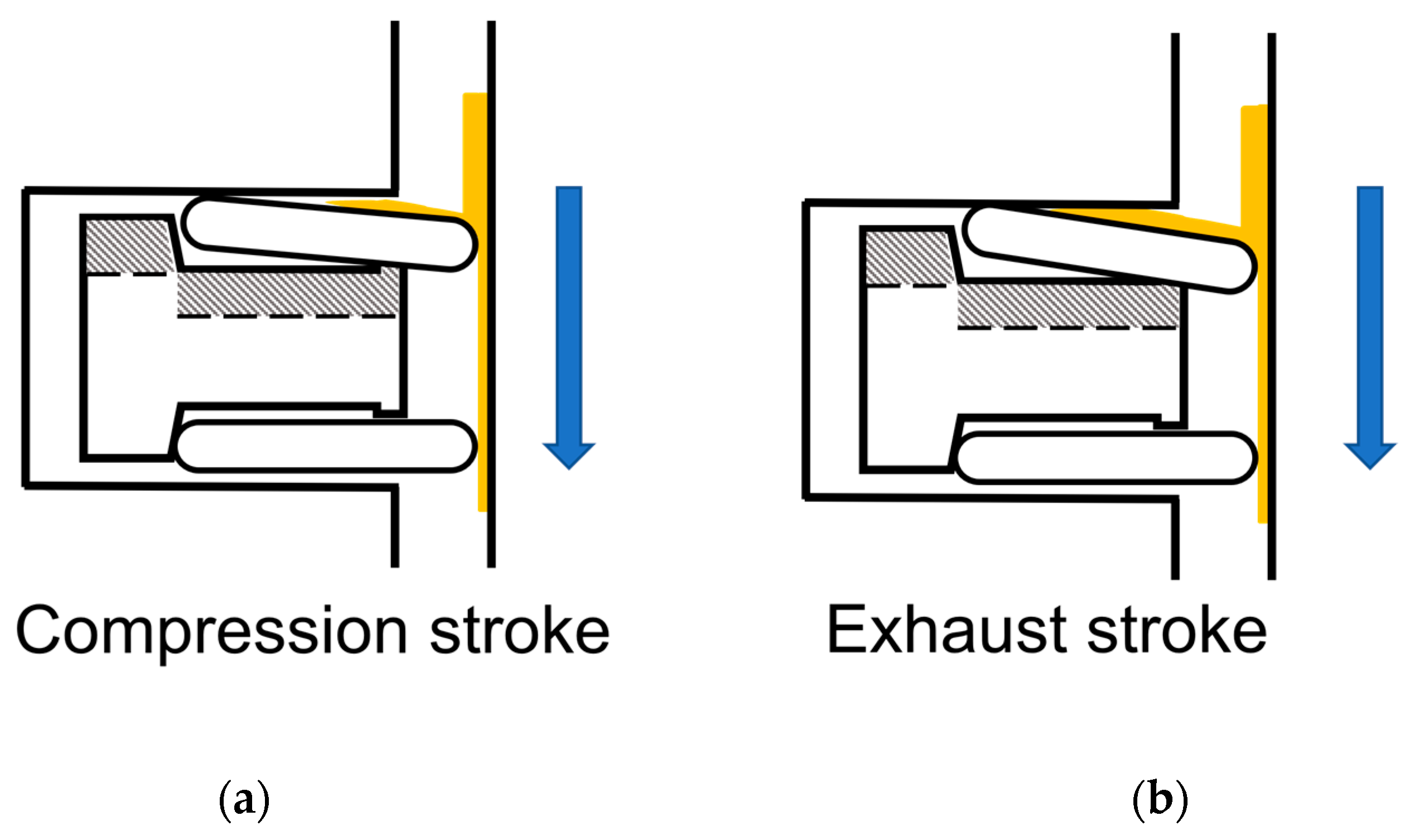
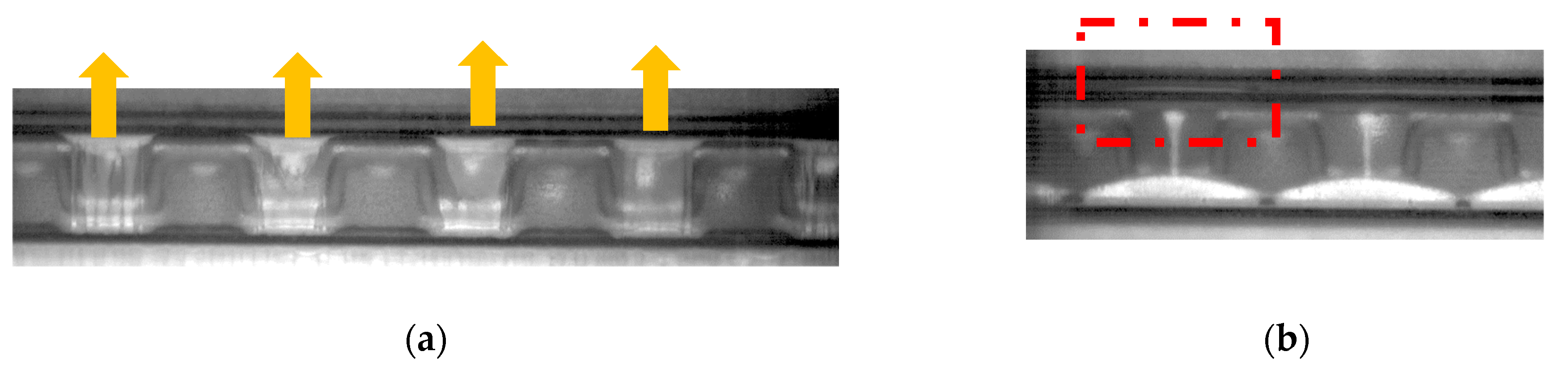
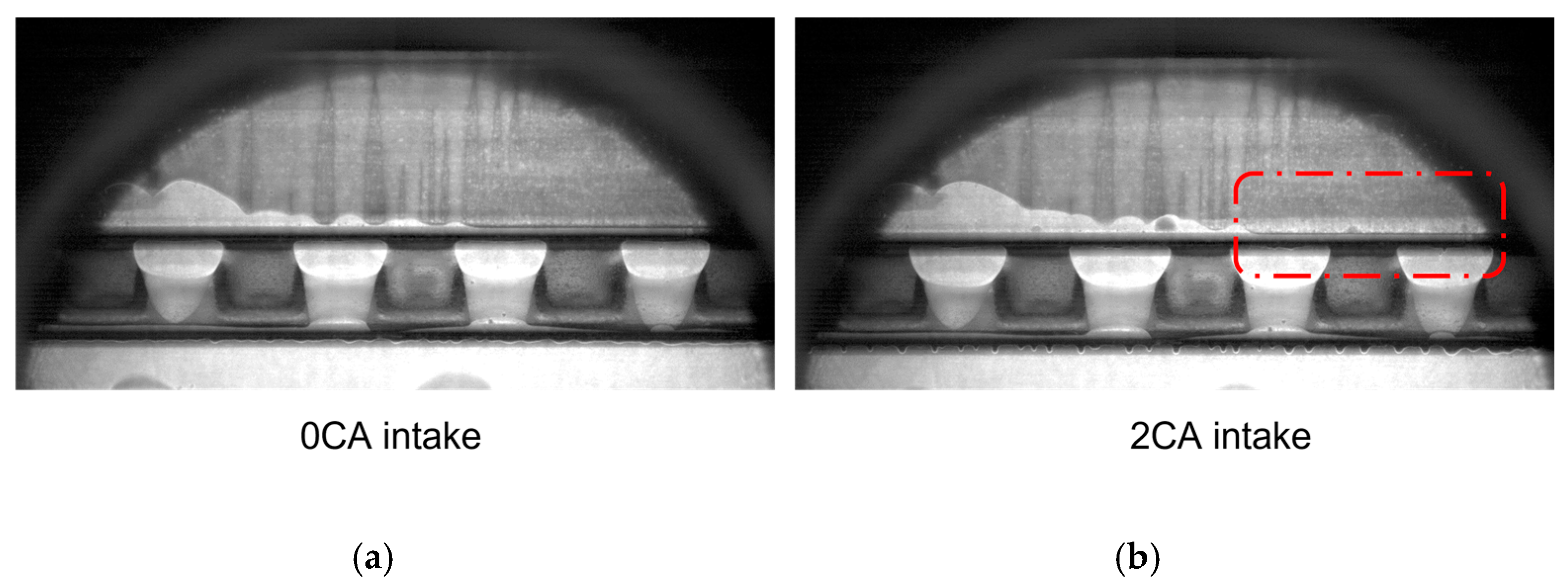
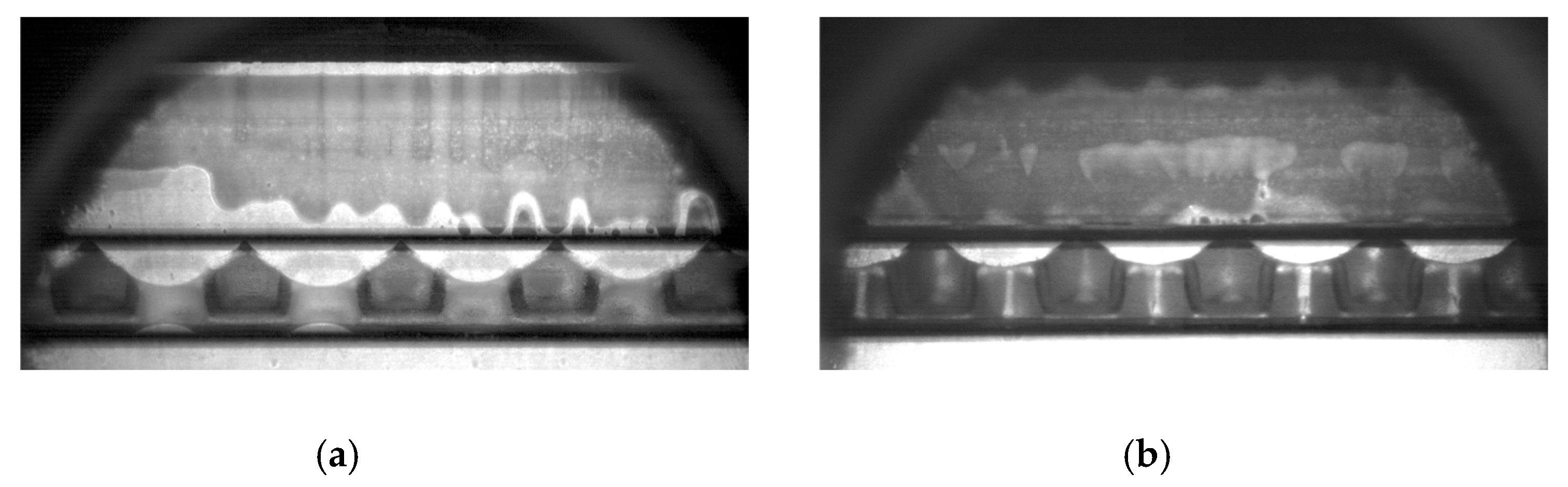
4.1. Source and Mechanism of Up-Scraping

Figure 8 shows the location of the contact point between the rails and liner across the full cycle. A positive value means the contact point is moved higher than the central line of the parabolic profile, indicating a negative twist and vice versa.
The oil source available to be up-scraped is the oil film left by the TPOCR during downstrokes. In the intake stroke, the friction and downward force from the expander tab that has an ear angle of 10 degrees together applied on the lower rail result in a positive twist which can enhance the down scrape ability. Additionally, the lower rail has enough time to overcome the suction force from the lower flank. While the upper rail remains flat, the lower rail is regulating the oil film thickness which allows less oil to pass than the upper rail. In the expansion stroke, the raised third land pressure can push the upper rail OD downwards and transfer the force through expander to lower rail. Thus, the lower rail was ‘pressed’ flat and allows more oil to pass. In addition, the upper rail’s negative twist can increase the leading edge’s rail liner clearance and allows more oil to pass than the flat lower rail. Similarly, during the expansion stroke the lower rail is controlling the oil film thickness. As a result, in both of the down strokes, the lower rail is regulating the oil film thickness. The expansion stroke’s lower rail dynamic can provide a thicker oil film on liner thus more oil source for the subsequent up-stroke. The demonstration is shown in Figure 9.
Figure 10 shows the oil film thickness distribution along the liner at 3000 rpm 700 mbar fired condition. The original point of the x axis represents the upper rail’s BDC location and the right side is the location of TDC. It indicates the oil film thickness on the liner available for the upper rail. As can be seen, the overall oil film is thicker at the exhaust stroke than that in the compression stroke.
During the two up-strokes (Figure 11), the upper rail both move the contact point higher which allows less oil to pass, namely providing the up-scraping ability. The exhaust has more twist than the compression stroke and allows less oil flow rate to pass, forming a stronger up-scraping ability. Since it has more oil source on the liner as well, the exhaust stroke can result in more oil leakage after reaching TDC.
Figure 12 shows the oil film distribution along the liner after the upper rail moved upwards. Thus, the difference between Figure 10 and Figure 12 indicates the amount of oil being scraped up in each stroke (Figure 13). Clearly, the up-scraping rate is higher at the exhaust stroke than the compression stroke. It explains the experimental result that more oil leakage can be observed at the subsequent intake stroke TDC.
In the up-stroke, the oil film is attached on liner thus has a relative velocity with the rings when reaching the upper rail. A stagnation point at the profile region can build up the pressure (Figure 14a). It provides the driving force for the up-scraped oil to flow into the clearance between upper rail and groove [23]. This up-scraped oil that is transferred to the piston and TPOCR upper groove clearance may be the source of oil that is squeezed out from the groove after the TDC of the intake stroke, as discussed earlier. On contrast, at the TDC of expansion stroke, the high pressure in the third land is pushing down the TPOCR. Even the friction force is pointing up in the downstroke, the pressure force is able to counteract that and keep the upper rail-groove interface open. Figure 14b shows a magnification view of the 15CA ATDC in the expansion stroke. The oil accumulation inside groove can be observed and moves down together with the piston. Thus, the up-scraped oil squeezing from the groove (Figure 4’s path 1.1 and 1.2) will not happen at the beginning of expansion stroke and explained the observation in Figure 7a.
There is an additional oil source to the upper rail when it travels down toward the BDC when the oil accumulation between the two rails bridge to the liner, driven by the inertia force. Although it is very difficult to tell, there seems to be more up-scraping in the bridged area, as shown in Figure 15. Figure 15a shows the OCR groove at the end of expansion stroke. The oil bridging can fully flood the leading edge of the upper rail, thus, leaving a thicker oil film on liner locally. The bridging happens at locations where the expander pitches are contacting with the lower rail. After the piston changes direction at BDC, more oil accumulation can be observed at the exact bridging locations as shown in Figure 15b. When the piston continued to move up, it can be flattened and form a continued bright oil line with additional oil accumulation during the up-scraping process.

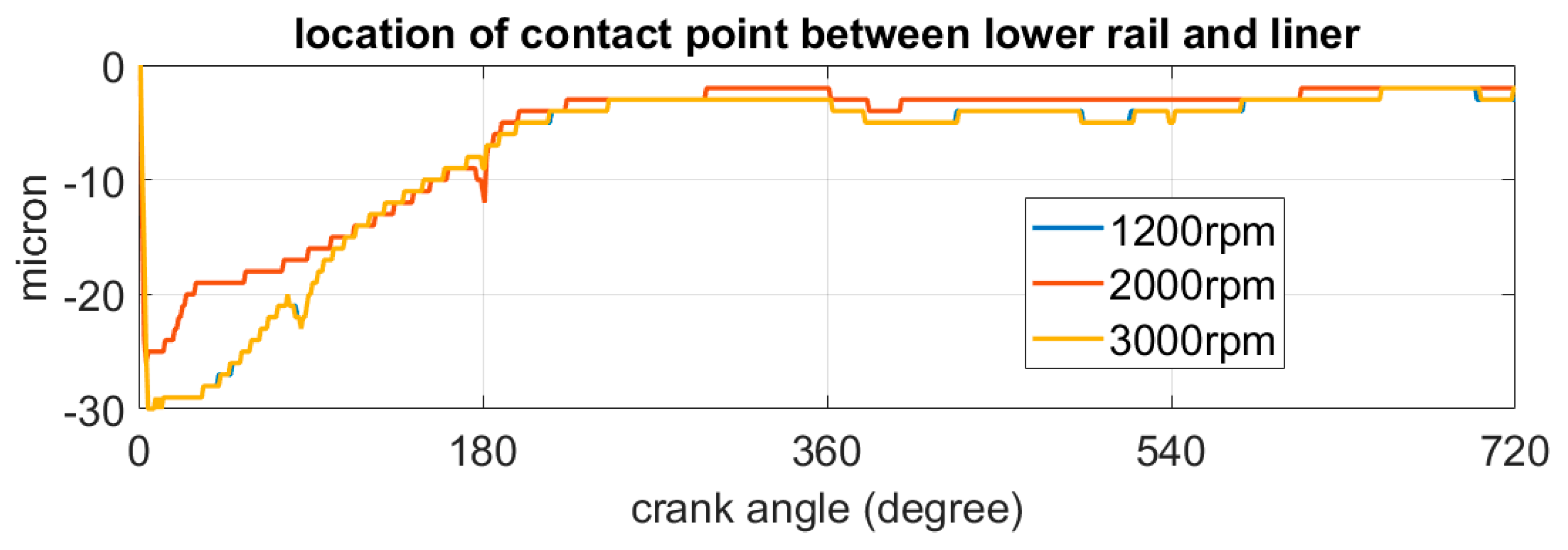
4.2. Dependency with Load and Speed

Since the exhaust stroke has significantly more up-scraping than the compression stroke, the comparison across different running conditions was performed at the beginning of the intake stroke. Figure 16 shows the oil leakage at the beginning of the intake stroke at 3000 rpm across different loads. It’s clear that a higher engine load results in more oil leakage.
Figure 17 shows the lower rail twist at all three tested engine loads at 3000 rpm. During the expansion stroke, the friction force is dragging the lower rail OD upwards which results in a positive twist, namely moving the contact point to a negative value. This force mainly comes from the tension of the expander and does not change with engine working conditions. Meanwhile, the high pressure in the third land is counteracting that applies a force to push down the upper rail’s OD. This force can be transferred to the lower rail through the contact between expander. The third land pressure can increase with the increase of the engine load. Thus, at higher engine loads, the lower rail can be pushed flatter by the pressure force which allows more oil to pass in the expansion stroke, providing more oil to the upper rail.
In the ensuing exhaust stroke when the actual up-scraping process happens, both the third land pressure and friction force applied on upper rail’s OD are pointing downwards. Since the friction force is mainly dependent on the expander’s tension, which doesn’t change either, it is the enhanced pressure force at higher load that causes more negative twist as shown in Figure 18. As a result, the higher engine load condition the upper rail can have, both more oil supply on the liner in the expansions stroke, and a stronger up-scraping ability in the exhaust stroke. This explains the observation that more oil leakage can be observed at the beginning of intake stroke at higher engine loads.
In the next set of experiments, the engine was running at 700 mbar fired condition across three engine speeds: 1200 rpm, 2000 rpm, and 3000 rpm. Through the experimental observation shown in Figure 19, the amount of oil leakage is also increasing at higher engine speeds. Through the modeling calculation, the rail twisting behavior does not change much with different engine speeds (Figure 20). However, an increased engine speed can result in an overall thicker oil film on the liner. Given the similar up-scraping mechanism, higher engine speed provides more oil source. In other words, the oil leakage from up-scraping mainly comes from the difference of ring dynamics in each cycle. With the same level or ratio of difference, a thicker oil film provides a larger base number. Thus, under a higher engine speed, more up-scraping oil leakage can be observed due to the increase of oil film thickness on the liner.
In addition, at higher engine speed, the oil bridging inside the OCR groove can happen earlier during the downstrokes. The higher inertia force and larger relative velocity to the liner is the major cause [23]. When the bridging happens, the oil can fully flood the leading edge and allows more oil to pass. An earlier bridging timing leaves a longer thickened oil film on the liner. With the same level of rail twist in the up-strokes, the additional oil source can also increase up-scraping at higher engine speeds.
Overall, the amount of oil leakage from up-scraping can increase with both engine load and speed. It matches the common trend of LOC measurement on engines equipped with a TPOCR that a higher LOC can happen at both a high speed and load [11]. This may indicate that the up-scraping oil leakage from the TPOCR may be the main source contributing to the overall LOC from the ring pack. On the other hand, this oil leakage to the liner by the TPOCR provides the oil for the top two rings to transport to the dry region to protect the liner and rings. Thus, one needs to optimize the amount of this leakage to limit LOC, while protecting the liner and rings.

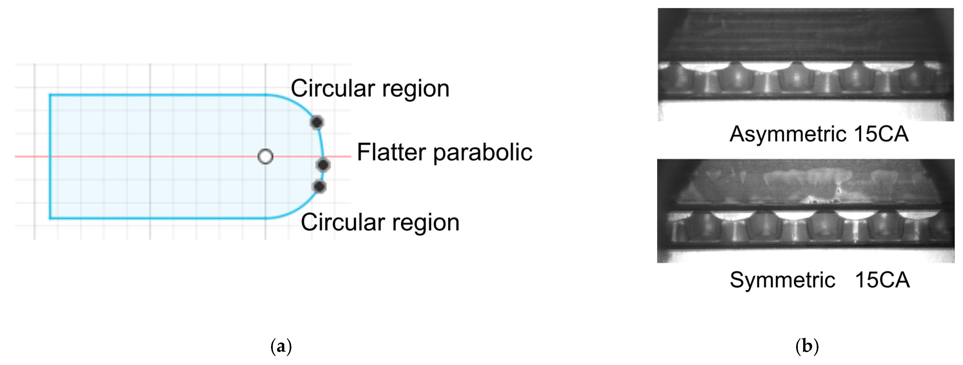
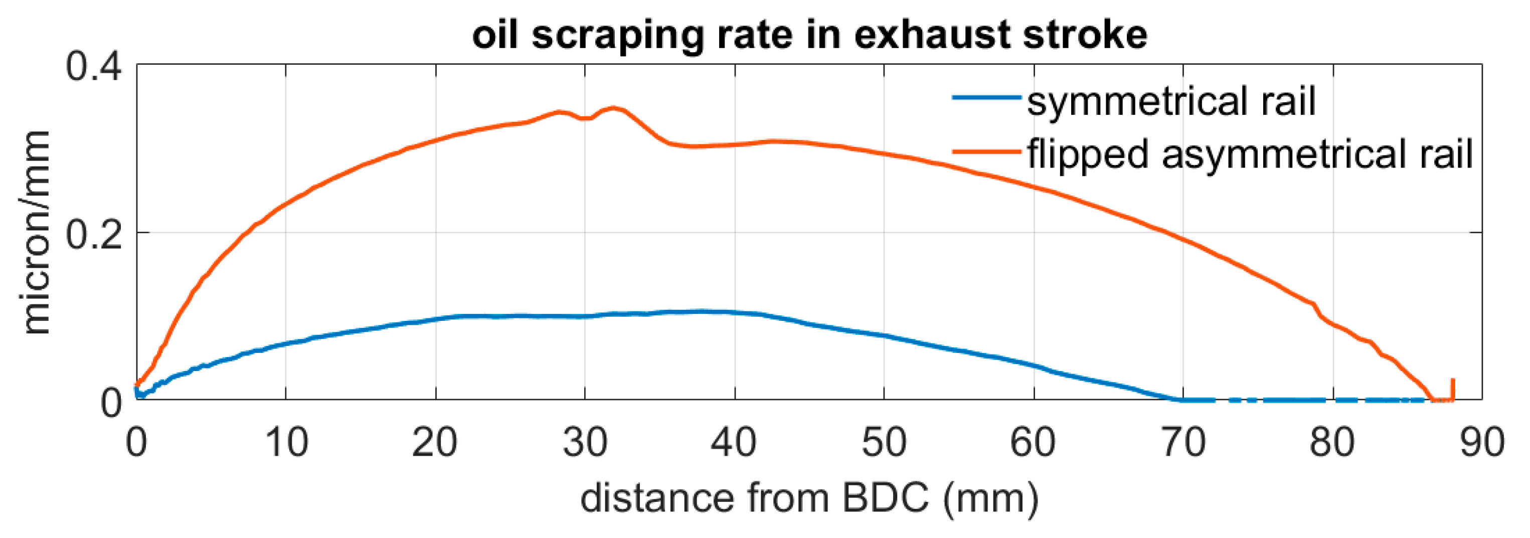
4.3. Asymmetrical Rail Profile

The oil up-scraping behavior is mainly coming from the upper and lower rail’s twist mechanism across different cycles, when equipped with the symmetrical rail profile TPOCR. The profile of the TPOCR rails can be divided into a circular region at the edge and a flatter parabolic contact region in the middle. A viable way to reduce or eliminate this up-scraping is using an asymmetrical rail profile by moving the vertex of the parabola to a location lower than the central line. With this offset, when the rails are experiencing the same negative twist in the up-strokes, the location of the minimum clearance between the rail and liner (called the minimum point or contact point) does not move as high as the symmetrical profile, such that the up-scraping can be reduced or eliminated. This asymmetrical profile was tested with both experiments and calculations using the model [15].
Figure 21a shows the configuration of the asymmetrical profile. In the tested TPOCR, the expander tension is the same as the one with the symmetrical profile. Both the upper and lower rail profiles have an offset lower than the center line. Theoretically, this design can fully remove the up-scraping by allowing the same oil film thickness to pass in the expansion and exhaust stroke. Figure 22 shows the modeling result that in the exhaust stroke, the oil film thickness before and after the upper rail is the same, introducing no oil up-scraping. The experimental observation in Figure 21b shows the comparison at 15 CA intake stroke at 3000 rpm 700 mbar fired conditions. The oil leakage can be largely eliminated as no oil squeezed out from the groove can be observed. This finding reinforces the hypothesis that the source of the oil leakage at TDC, more specifically, sources 1.1 and 1.2 in Figure 4, is from up-scraping.
In the double magnification view’s experimental observation, it can be seen that the oil leakage path 2 to the liner (Figure 4b), namely reattachment, as Fang studied [16] still exists at the TDC of upper rail. Further work is needed to understand the mechanism for this oil source. Figure 23 shows firstly the oil streak at the trailing edge of the upper rail at 5CA ATDC intake stroke. It represents the oil reattachment to the liner. Then, when the top two rings pass this location, an enhanced oil film thickness between the ring and liner can be observed. Figure 23 shows the 21CA and 35CA in intake stroke when the second ring and top ring passed the same region. These amounts of oil can still help lubricate the dry region when the top ring moves up again in the compression stroke. The protection of the running interface and reduction of LOC are two counteracting factors that needed to be balanced when designing the ring pack. Completely eliminating the oil leakage is not necessarily an optimal solution. Rather, a balance of oil leakage from the TPOCR should be found that can supply enough oil to protect the top two rings without introducing excessive LOC.

4.4. Asymmetrical Rail Flipped Installation

In order to further verify the profile’s effect on the oil up-scraping mechanism, the TPOCR assembly was installed with both the upper and lower asymmetrical rails flipped. That is, installed with the vertex of parabolic contact region higher than the central line. With the similar ring dynamics behavior, during down-strokes, both rails can allow more oil to pass through the rail liner interface and leave a thicker oil film on the liner than the rails with symmetrical profiles. In contrary, these flipped rails allow less oil to pass during the ensuing up-stroke than the ones with symmetrical profiles, as a result, more up-scraping occurs with these flipped rails than the one with symmetrical profiles, as shown in Figure 24’s modeling calculation.
The experimental observation shows a massive oil accumulation in the third land at the end of exhaust stroke, indicating an increased oil leakage from the TPOCR. Figure 25a shows the 2DLIF image at the TDC of the intake stroke, where the oil accumulation at the lower part of the third land is high, making it difficult to identify the additional oil leakage at TDC. Figure 25b shows 2CA at the intake stroke when the piston’s down movement closes the clearance between the upper rail and groove. Nonetheless, an increased amount of oil has been squeezed out from the groove in the red-dashed region that verifies the up-scraped oil has entered the groove and result in a leakage path.
On the liner above the TDC of upper rail, oil streaks can be observed as a result of oil bridging in the third land. Figure 26 shows the process of third land oil bridging. Figure 26a shows at 18CA before reaching the TDC, it can be observed a bright line at the bottom of the second ring and leaves oil streak on the liner. It indicates the hook chamfer on the second ring is quite full, such that the oil driven by the upward inertia force can flow to the liner [25,26,27]. Figure 26b shows the demonstration of the second ring’s section view. Under this condition, the second ring will pump oil upwards and result in massive LOC [10].
Overall, as the piston continues the down movement, massive oil leakage has filled the volume in the third land and make it hard to distinguish the path to liner and piston land. But the mechanisms remain similar as the case of symmetrical rail. Figure 27 shows a comparison between the observation of the flipped asymmetrical rail and symmetrical rail. It is clear that the flipped assembly could result in more oil leakage. It demonstrated the importance of the rail profile’s effect on the oil up-scraping mechanism.

5. Conclusions

In this work, both an experimental approach and modeling analysis were used to study the oil source and destination of oil leakage through the TPOCR. An oil up-scraping mechanism of the TPOCR, which is a major factor to cause oil leakage when running at positive blowby condition [10], was identified. It is the first time this leakage was uncovered and explained and the key findings are listed below:
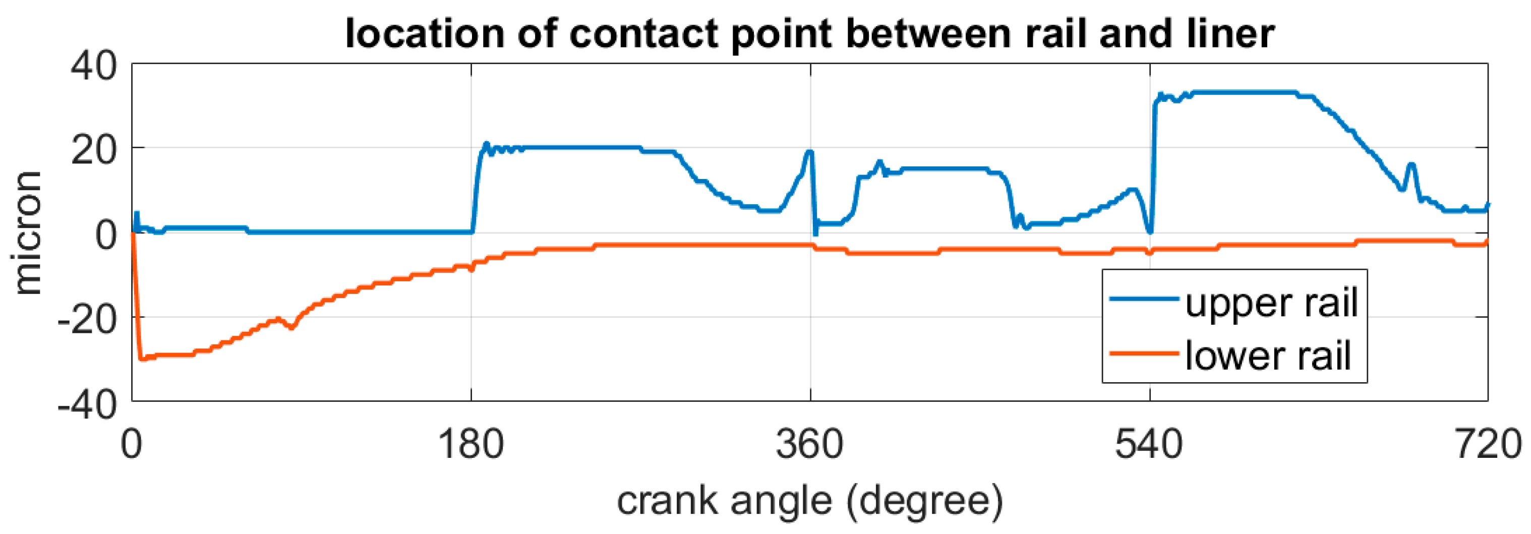
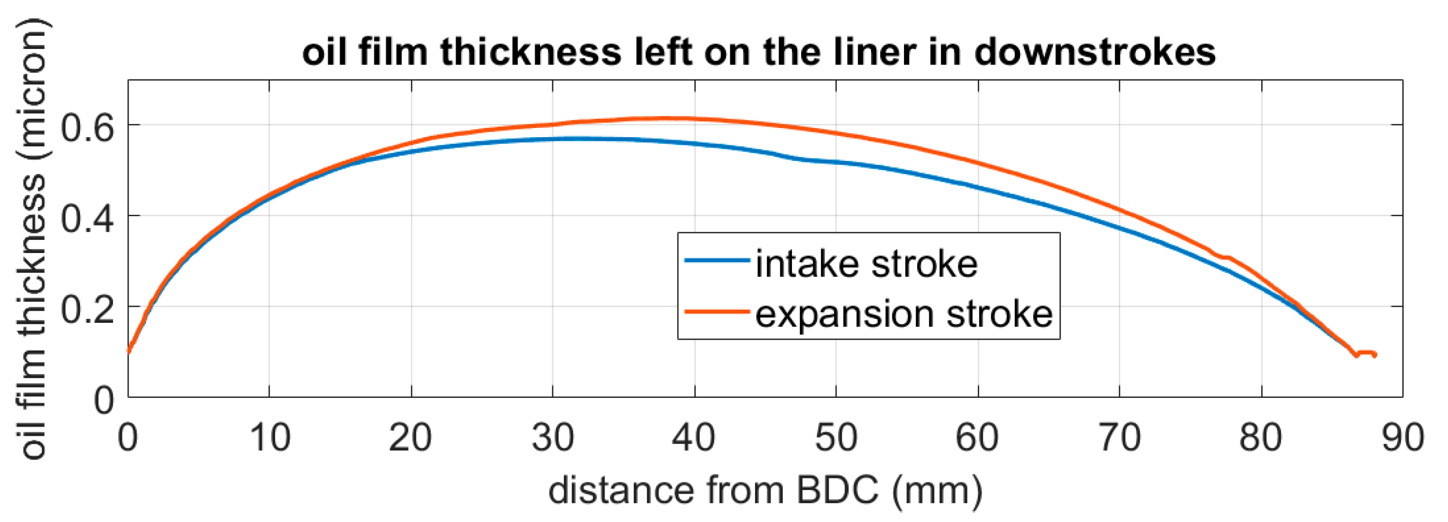
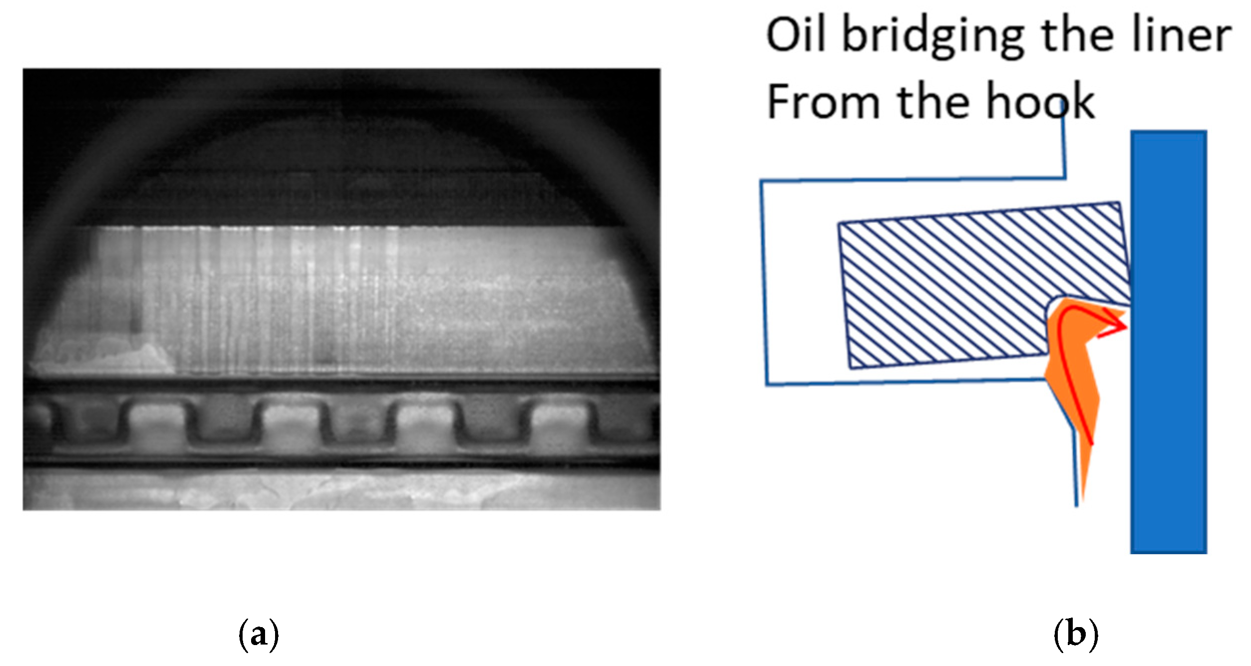
  • In the up-strokes, the ring dynamics of the TPOCR can cause a negative twist of the upper rail, which reduces the oil flow rate at the leading edge. As a result, the upper rail with a symmetrical or a flipped asymmetrical profile can scrape up the oil film on the liner. The part of the scraped oil can be pushed into the OCR groove clearance and the rest is stored in the upper part of the rail OD.
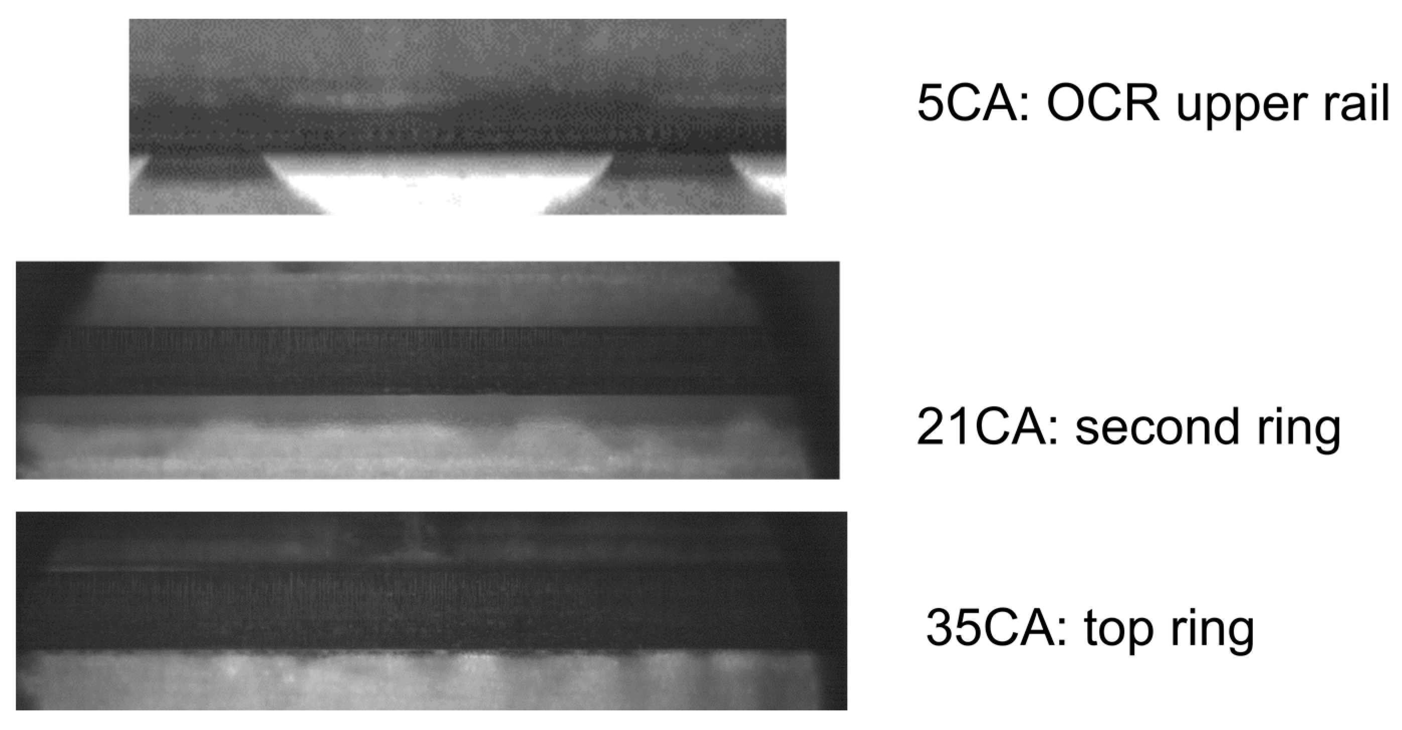
  • At the TDC. when the piston changes direction, the up-scraped oil can leak to both the third land and liner. More specifically, the oil inside groove can be squeezed out to both the third land and liner and the oil stored at the upper part of the rail OD is reattached to the liner. The oil leaked to the liner (Sources 1.2 and 2) is a major contributor to cause LOC and provide lubrication to the dry region at the same time. The interaction of these two oil sources on the liner with the top two rings will lead to wetting of the dry region as well as possible up- or/and down-scraping by the top ring. Consequently, the amount of these two oil sources is critical to both LOC and proper lubrication of the top ring groove and liner dry region, which will be studied in the future.
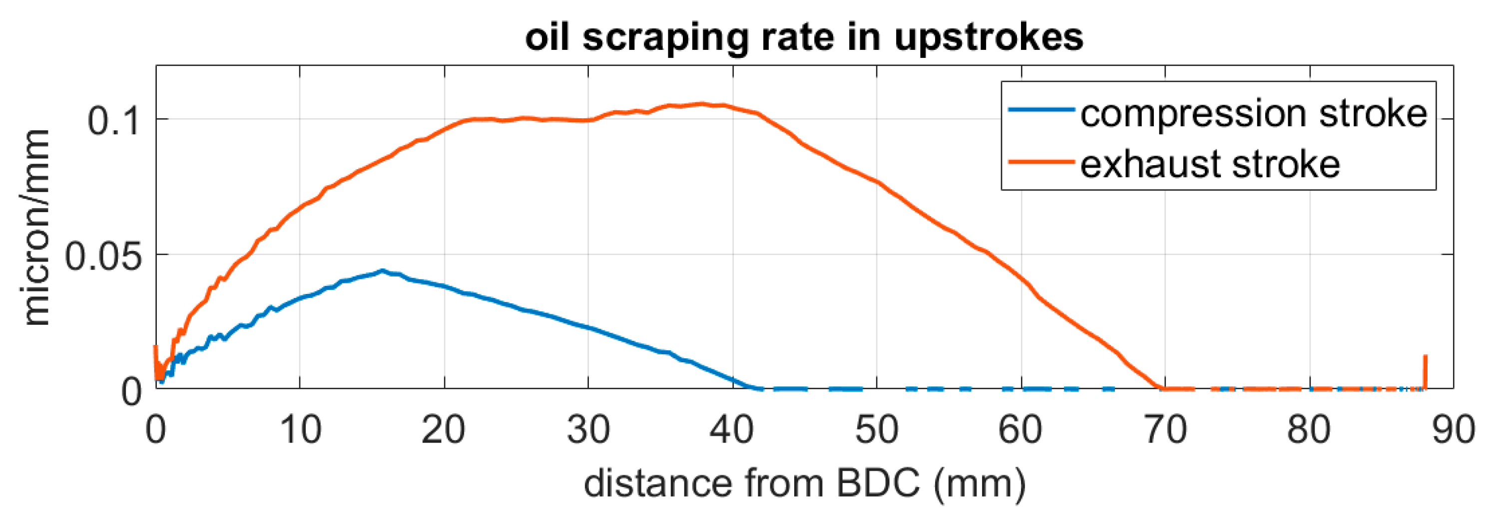
  • Higher engine loads can experience more oil up-scraping. This is because during the expansions stroke, a raised third land pressure can push the TPOCR downwards to generate more negative twist to the upper rail while holding the lower rail with less positive twist, both resulting in more oil to pass the liner with higher load. Additionally, in the exhaust stroke, a higher load results in an increased negative twist on the upper rail and enhances the scraping by the upper rail.
  • Using the asymmetrical rail profile by moving the parabola’s vertex lower than the center line can eliminate the oil up-scraping leakage. The flipped asymmetrical rail assembly’s increased oil leakage further proves the effectiveness of rail profile effect. However, the up-scraping is also an important source to provide lubrication to the dry region. A proper amount of oil leakage or supply should be achieved when considering the ring pack design.

Author Contributions

Design and preparation of the experiment, M.L.; Experimental investigation and modeling calculation, M.L.; writing the manuscript, M.L.; Supervising and revising the manuscript, T.T. All authors have read and agreed to the published version of the manuscript.

Funding

This work was sponsored by Mercedes-Benz and the Consortium on Lubrication in Internal Combustion Engines in the Sloan Automotive Laboratory, Massachusetts Institute of Technology. The consortium members were Mahle, Shell, Rolls-Royce Solutions, Toyota, Volkswagen Group, Volvo Trucks, and Weichai Power.

Data Availability Statement

Data are contained within the article.

Conflicts of Interest

The authors declare no conflict of interest.

References

  1. Richardson, D.E. Review of Power Cylinder Friction for Diesel Engines. J. Eng. Gas Turbines Power 2000, 122, 506–519. [Google Scholar] [CrossRef]
  2. Turnbull, R.; Dolatabadi, N.; Rahmani, R.; Rahnejat, H. An assessment of gas power leakage and frictional losses from the top compression ring of internal combustion engines. Tribol. Int. 2020, 142, 105991. [Google Scholar] [CrossRef]
  3. Ferrarese, A.; Marques, G.; Tomanik, E.; Bruno, R.; Vatavuk, J. Piston ring tribological challenges on the next generation of flex-fuel engines. SAE Int. J. Engines 2010, 3, 85–91. [Google Scholar] [CrossRef]
  4. Ulrich, A.; Czerwinski, J.; Mayer, A.; Mooney, J.J.; Kasper, M. Metal oxide particle emissions from diesel and petrol engines. In Proceedings of the SAE 2012 World Congress Exhibition, Detroit, MI, USA, 24–26 April 2012. [Google Scholar]
  5. Premnath, V.; Khalek, I.; Morgan, P.; Michlberger, A.; Sutton, M.; Vincent, P. Effect of lubricant oil on particle emissions from a gasoline direct injection light-duty vehicle. In Proceedings of the SAE International Powertrains, Fuels and Lubricants Meeting, Heidelberg, Germany, 17–19 September 2018. [Google Scholar]
  6. Leach, F.; Chapman, E.; Jetter, J.; Rubino, L.; Christensen, E.; John, P.; Fioroni, G.; McCormick, R. A review and perspective on particulate matter indices linking fuel composition to particulate emissions from gasoline engines. SAE Int. J. Fuels Lubr. 2021, 15, 3–28. [Google Scholar] [CrossRef]
  7. Schwanzer, P.; Schillinger, M.; Mieslinger, J.; Walter, S.; Hagen, G.; Märkl, S.; Haft, G.; Dietrich, M.; Moos, R.; Gaderer, M.; et al. A synthetic ash-loading method for gasoline particulate filters with active oil injection. SAE Int. J. Engines 2021, 14, 493–505. [Google Scholar] [CrossRef]
  8. Amann, M.; Alger, T. Lubricant Reactivity Effects on Gasoline Spark Ignition Engine Knock. SAE Int. J. Fuels Lubr. 2012, 5, 760–771. [Google Scholar] [CrossRef]
  9. Kawahara, N.; Tomita, E. Visualization of auto-ignition and pressure wave during knocking in a hydrogen spark-ignition engine. Int. J. Hydrogen Energy 2009, 34, 3156–3163. [Google Scholar] [CrossRef]
  10. Li, M.; Tian, T. Effect of Blowby on the Leakage of the Three-Piece Oil Control Ring and Subsequent Oil Transport in Upper Ring-Pack Regions in Internal Combustion Engines. Lubricants 2022, 10, 250. [Google Scholar] [CrossRef]
  11. Adelmann, J.; Becker, S.; Rabute, R.; Bruno, R. Optimized oil control ring design for emission reduction. In Zylinderlaufbahn, Kolben, Pleuel; VDI Reports; VDI Wissenforum GmbH: Düsseldorf, Germany, 2018; pp. 91–103. [Google Scholar]
  12. Froelund, K.; Menezes, L.; Johnson, H.; Rein, W. Real-Time Transient and Steady-State Measurement of Oil Consumption for Several Production SI-Engines. In Proceedings of the International Spring Fuels & Lubricants Meeting, Orlando, FL, USA, 7–9 May 2001. SAE Technical Paper 2001-01-1902. [Google Scholar] [CrossRef]
  13. Tian, T.; Wong, V.W.; Heywood, J.B. Modeling the Dynamics and Lubrication of Three Piece Oil Control Rings is Internal Combustion Engines. SAE Trans. 1998, 107, 1989–2006. [Google Scholar] [CrossRef]
  14. Li, Y. Study of the Factors That Influence the Lubrication of the Three-Piece Oil Control Ring. Master’s Thesis, Massachusetts Institute of Technology, Cambridge, MA, USA, 2017. [Google Scholar]
  15. Zhang, W. Modeling Internal Combustion Engine Three-Piece Oil Control Ring Coupling Reduced Order Oil Transport Based on Neural Network. Master’s Thesis, Massachusetts Institute of Technology, Cambridge, MA, USA, 2020. [Google Scholar]
  16. Mochizuki, K.; Sasaki, R.; Yazawa, M.; Iijima, N.; Usui, M. Prediction and Experimental Verification for Oil Transport Volume around Three-Piece Type Oil Control Ring Affecting Lubricating Oil Consumption. SAE Int. J. Adv. Curr. Pract. Mobil. 2023, 5, 595–609. [Google Scholar] [CrossRef]
  17. Ito, A.; Tsuchihashi, K.; Nakamura, M. A Study on the Mechanism of Engine Oil Consumption—Oil Upwards Transport via Piston Oil Ring Gap. In Proceedings of the SAE 2011 World Congress & Exhibition, Detroit, MI, USA, 12–14 April 2011. SAE Technical Paper 2011-01-1402. [Google Scholar] [CrossRef]
  18. Kikuhara, K.; Sekiya, H.; Ito, A.; Hayashi, H. A Study on Numerical Analysis Model of the Oil Film under the Oil Control Ring Considering the Generation Mechanism of Oil Pressure. Trans. Soc. Automot. Eng. Jpn. 2017, 48, 225–232. [Google Scholar] [CrossRef]
  19. Hasegawa, H.; Kikuhara, K.; Nishijima, S.; Suzuki, H.; Ito, A.; Sekiya, H.; Akamatsu, H. The Effect of the Position and Number of Oil Drain Hole on the Oil Pressure Generating under the Oil Ring with Relation to Oil Consumption. Trans. Soc. Automot. Eng. Jpn. 2017, 48, 59–64. [Google Scholar] [CrossRef]
  20. Kikuhara, K.; Sekiya, S.; Ito, A.; Hayashi, H. A Numerical Analysis on the Effect of Several Factors on the Oil Pressure under Oil Control Ring Which Relates to Oil Consumption. Trans. Soc. Automot. Eng. Jpn. 2018, 49, 282–289. [Google Scholar] [CrossRef]
  21. Li, M.; Zhong, X.; Ahling, S.; Tian, T. An Investigation of Oil Supply Mechanisms to the Top of the Liner in Internal Combustion Engines. In Proceedings of the 2023 JASE/SAE Powertrains, Energy and Lubricants International Meeting, Kyoto, Japan, 29 August–1 September 2023. SAE International JSAE 20239052/SAE 2023-32-0031. [Google Scholar]
  22. Ahling, S. Elements of Lubricant Transport Critical to Piston Skirt Lubrication and to Leakage into the Piston Ring Pack in Internal Combustion Engines. Ph.D. Thesis, Massachusetts Institute of Technology, Cambridge, MA, USA, 2021. [Google Scholar]
  23. Fang, T. Fluid Mechanics of Lubricant Transport in Non-Contact Regions in the Piston Ring Pack in Internal Combustion Engines. Ph.D. Thesis, Massachusetts Institute of Technology, Cambridge, MA, USA, 2019. [Google Scholar]
  24. Tian, T. Modeling the Performance of the Piston Ring-Pack in Internal Combustion engines. Ph.D. Thesis, Massachusetts Institute of Technology, Cambridge, MA, USA, 1997. [Google Scholar]
  25. Przesmitzki, S. Characterization of Oil Transport in the Power Cylinder of Internal Combustion Engines during Steady State and Transient Operation. Ph.D. Thesis, Massachusetts Institute of Technology, Cambridge, MA, USA, 2019. [Google Scholar]
  26. Fang, T. Computations and Modeling of Oil Transport between Piston Lands and Liner in Internal Combustion Engines. Master’s Thesis, Massachusetts Institute of Technology, Cambridge, MA, USA, 2014. [Google Scholar]
  27. Vokac, A. An Experimental Study of the Oil Evolution in Critical Piston Ring Pack Regions and the Effects of Piston and Ring Designs in an Internal Combustion Engine Utilizing Two-Dimensional Laser Induced Fluorescence and the Impact on Maritime Economics. Master’s Thesis, Massachusetts Institute of Technology, Cambridge, MA, USA, 2004. [Google Scholar]
Figure 1. The optical test engine setup. Configuration of engine, high speed camera and laser.
Lubricants 11 00522 g001
Figure 2. The optical window’s configuration with the camera setup: (a) A photo of the optical window with the piston and rings in the middle; (b) Demonstration of two camera views, full view with 128 × 1024 resolution to cover the full window on the left, magnification view with 1024 × 1024 resolution to divide the window into 8 square regions.
Lubricants 11 00522 g002
Figure 3. Oil behavior caused by the TPOCR around the TDC: (a) 5CA before the TDC in the late exhaust stroke, a bright oil line on the upper rail profile observed; (b) 15CA after the TDC in the early intake stroke, oil leakage observed. Engine condition: 3000 rpm 700 mbar.
Lubricants 11 00522 g003
Figure 4. Oil leakage path at the TDC of intake stroke: (a) LIF image took during the experiment; (b) a demonstration of the section view to show the relation between ring, groove, liner, and oil. Engine condition: 3000 rpm 700 mbar.
Lubricants 11 00522 g004
Figure 5. A step-by-step observation of the oil leakage after the TDC: (a) double magnification view of 15CA after the TDC intake stroke, the red dashed area will be zoomed out in (be), followed by the sequence of piston downwards movement; (b) the second ring reaches the oil puddle on liner. Some oil was scraped down and form the bright line, some enter the interface between the second ring and liner; (c) oil pass the second ring; (d) oil enters the top ring and liner interface; (e) the top ring moves down, leave a thickened oil film on liner.
Lubricants 11 00522 g005
Figure 6. The late compression stroke when the top ring reaches the thickened oil film in Figure 5: (a) the oil film enters the leading edge of top ring barrel shape, a small oil puddle squeezed up can be observed and carried upwards until the TDC; (b) oil film leaving the trailing edge of top ring’s barrel shape profile.
Lubricants 11 00522 g006
Figure 7. Oil leakage behavior around the TDC of expansions stroke: (a) 15CA after the TDC in the early expansion stroke, only oil reattachment to the liner can be observed (path 2); (b) a comparison of 5CA before the TDC in late exhaust on the left and the compression stroke on the right. The bright oil line is more obvious in the exhaust stroke.
Lubricants 11 00522 g007
Figure 8. Location of contact point between the rail and liner across the full stroke.
Lubricants 11 00522 g008
Figure 9. A demonstration of the rail twist and oil film thickness on liner during the downstrokes, the liner relative velocity is upwards: (a) intake stroke; (b) expansion stroke.
Lubricants 11 00522 g009
Figure 10. Oil film thickness left on liner during the downstrokes.
Lubricants 11 00522 g010
Figure 11. A demonstration of rail twist and oil film thickness on liner during the up-strokes, the liner relative velocity is downwards: (a) compression stroke; (b) exhaust stroke.
Lubricants 11 00522 g011
Figure 12. Oil film thickness after the upper rail in the up-strokes.
Lubricants 11 00522 g012
Figure 13. Oil up-scraping rate at each location across the up-stroke.
Lubricants 11 00522 g013
Figure 14. Up-scraped oil inside the groove: (a) in the up-stroke, the pressure built up in the OD can push the up-scraped oil to flow inside the clearance between upper rail and groove; (b) 3000 rpm 700 mbar 15CA after the TDC in expansion stroke, the high pressure in third land is pushing the upper rail down and prevent the oil inside groove from being squeezed out.
Lubricants 11 00522 g014
Figure 15. Oil bridging’s effect on the up-scraping: (a) the bridging happens at the late downstroke, fully flooding the inlet of upper rail at the locations where the expander pitches are down; (b) after the piston changes direction at BDC, more oil scraped up can be observed at the bridging region.
Lubricants 11 00522 g015
Figure 16. Oil up-scraping at 3000 rpm different engine loads.
Lubricants 11 00522 g016
Figure 17. The location of contact point between the lower rail and liner in different engine loads at 3000 rpm.
Lubricants 11 00522 g017
Figure 18. The location of the contact point between the upper rail and liner in different engine loads at 3000 rpm.
Lubricants 11 00522 g018
Figure 19. Oil up-scraping at 3000 rpm different engine speeds.
Lubricants 11 00522 g019
Figure 20. The location of contact point between lower rail and liner in different engine speeds.
Lubricants 11 00522 g020
Figure 21. The demonstration and observation of asymmetrical rail behavior: (a) the demonstration of the asymmetrical rail at the flat position and negative twist; (b) the comparison between the symmetrical and asymmetrical rail’s oil leakage at 15CA intake stroke at 3000 rpm 700 mbar.
Lubricants 11 00522 g021
Figure 22. Oil film thickness before and after the upper rail in the exhaust stroke at 3000 rpm 700 mbar when equipped with asymmetrical rails.
Lubricants 11 00522 g022
Figure 23. Step-by-step observation of the beginning of the intake stroke when the top two rings passed the oil reattachment area on the liner.
Lubricants 11 00522 g023
Figure 24. Oil up-scraping rate in the exhaust stroke for the symmetrical rail and flipped asymmetrical rail at 3000 rpm 700 mbar.
Lubricants 11 00522 g024
Figure 25. Oil up-scraping behavior at the late exhaust and early intake stroke TDC: (a) 0CA intake stroke; (b) 2CA intake stroke.
Lubricants 11 00522 g025
Figure 26. Oil bridging in the third land at the late exhaust stroke: (a) observation of the second ring hook chamfer and oil streaks bridged to the liner; (b) a demonstration of the second ring hook chamfer’s section view.
Lubricants 11 00522 g026
Figure 27. Oil leakage observed at the beginning of the intake stroke 15CA: (a) both asymmetrical rails flipped installation; (b) symmetrical rail.
Lubricants 11 00522 g027
Table 1. Engine Specifications.
Engine Characters
TypeSpark Ignition 4 Valves
Bore86.6 mm
Stroke88.0 mm
Displacement0.511 L
Max specific power37.3 kW/L @ 5400 rpm
Max specific torque80 Nm/L @ 4200 rpm
LubricantSAE 0W20
Top ring type1.2 mm thick barrel shape
Second ring type1.5 mm thick hook chamfer
Oil Control Ring type2 mm thick TPOCR
Disclaimer/Publisher’s Note: The statements, opinions and data contained in all publications are solely those of the individual author(s) and contributor(s) and not of MDPI and/or the editor(s). MDPI and/or the editor(s) disclaim responsibility for any injury to people or property resulting from any ideas, methods, instructions or products referred to in the content.

