Article

Tribological Synergism of Anodic Aluminum Oxide Surface Containing Micro-Holes and Nanopores under Lubricated Reciprocation

School of Mechanical Engineering, Chung-Ang University, Seoul 06974, Republic of Korea
Lubricants 2023, 11(12), 533; https://doi.org/10.3390/lubricants11120533
Submission received: 27 October 2023 / Revised: 12 December 2023 / Accepted: 13 December 2023 / Published: 15 December 2023
(This article belongs to the Special Issue Selected Papers from the K-TRIB2023)

Abstract

:
Micro-drilled aluminum surfaces containing micro-holes were anodized to produce nanopores over the machined and lapped surfaces. The anodized nanopores had an approximate diameter of 30–40 nm and a depth distribution of 20–30 μm from the surface. The diameter and depth of the machined micro-holes were 125 μm and 300 μm, respectively. Anodization itself did not change the surface roughness because the nanopores were very small. Ball-on-disk reciprocating tests were performed under lubricated conditions for 2 h using a frequency of 2 Hz, a load of 2 N, and a travel distance of 5 mm. The results showed that both the micro-drilled and anodized surfaces greatly reduced the coefficient of friction compared with the lapped bare surface; however, the coefficient of friction of the hole-textured specimen was not maintained till the end. Contrary to expectations, the lubricant retention capability of the textured structure declined because of hole failure that occurred during oscillation. This gradually increased friction until the end of the reciprocating test. When the micro-drilled surface was anodized, the coefficient of friction decreased again, implying that non-anodized micro-holes alone were ineffective for reducing friction. The surface hardness of Al increased owing to anodization, and thus the micro-holes remained intact. Therefore, it is concluded in this study that a prerequisite for friction reduction in Al is to increase the hardness to minimize the failure of micro-holes, which can be achieved by anodization. The synergistic lubricant retention capability can be maintained by the presence of both nanopores and micro-holes.

Graphical Abstract

1. Introduction

Aluminum (Al) and its alloys are an important engineering material and widely used in various industries because of their low weight, high specific strength, and manufacturability. However, pure aluminum is not sufficient as a mechanical element or structural component, owing to its high ductility and weakness. Therefore, aluminum alloys composed of various alloying elements are typically preferred and used in practice. However, it is not necessary to use heat-treated high strength aluminum alloys with superior mechanical properties, which are costly and usually far beyond conventional design purposes.
All mechanical properties need not be excellent for design and material selection. In some cases, either high hardness or wear resistance, rather than exceptional bulk material properties, is required. Of course, wear resistance is largely accompanied by high hardness of the material. In particular, when the surface properties have to be considered, surface treatments such as anodization, chemical conversion coating, plating, and deposition such as chemical vapor deposition (CVD) and physical vapor deposition (PVD) are very useful. Surface treatments can improve surface properties and protect surfaces from corrosion under chemically hostile environments, wear, and physical impacts, such as erosion. Among these treatments, anodization of aluminum has been widely exploited and continuously expanding its application in the field of nanotechnology.
Anodization is an electrolytic passivation process that produces a surface oxide layer of Al (Al2O3) on metal. The oxide thickness by anodization in electrolytes is greater than that obtained under natural conditions. In fact, Al rapidly oxidizes, which makes its surface much harder and stronger than that of pure Al, leading to high resistance to corrosion and wear with excellent hardness. Therefore, anodization of Al can become an excellent method for wear resistance.
There are two types of anodic aluminum oxides: barrier- and porous-type oxide films. In early studies on anodic aluminum oxides (AAOs), porous-type oxide drew great attention owing to its vast applicability in various nanotechnology fields. Anodization is primarily used because of the formation of a multi-porous superficial layer, which can be highly useful in many engineering designs. Masuda et al. [1] introduced a new era of Al anodization research by introducing highly ordered nanoholes formed on an Al surface. Al with high purity (>99.99%) was anodized using 0.3 M oxalic acid solution at 40 V, and improvement in structural regularity was observed at long periods of anodization. They produced highly ordered honeycomb nanohole arrays of Pt and Au by replicating the honeycomb structure of anodic porous alumina via a two-step process, where the diameter and depth were 70 nm and 1–3 nm, respectively. An interesting feature of the nanoporous Au plate is its reddish surface, which differs from that of ordinary Au.
In particular, AAO is widely used in the field of surface treatments because of its corrosion resistance and wear resistance characteristics. For example, Al after anodization obtains an increased corrosion resistance by forming an oxide layer on its surface. In addition, hardness also can be enhanced because of the hard oxide layer. Such improvements then can play an important role in tribology applications. Takaya et al. [2] prepared the anodic oxide coating of Al that is impregnated with iodine compound and performed friction and wear test. They found out that the dynamic coefficient of friction decreased to approximately 0.1. According to Lee et al. [3], tribo-chemical interaction produced an oxide layer, and its lubricant reservoir capability was better than that of the pores. It is interesting to note that the nanopores were beneficial only under dry condition with water infiltration. In addition, no significant decrease was obtained from the nanostructures having different porosity (10–50%). Other studies that deal with nanostructures over anodic surface are also highly interesting. For example, Tu et al. [4] prepared amorphous carbon nanorods by catalytic chemical vapor deposition (CVD) on an anodic aluminum oxide. Before the CVD, the samples were electropolished in an aqueous solution of sulfuric acid and phosphoric acid. They carried out ball-on-disk sliding tests in vacuum condition. The results showed that friction measured in vacuum was low and stable, and it was because of the good chemical stability of the amorphous carbon nanorods. Similar work [5] using an aligned film of amorphous carbon nanorods was also performed under different environmental conditions, and the results showed that the tribological properties were differently influenced by vacuum, humid air, and oxygen-rich atmosphere. According to Poznyak et al. [6], porous aluminum oxide films (PAOFs) were obtained by galvanostatic aluminum anodizing at 0.6 M malonic acid (MA) containing up to 4.0 g·L−1 arsenazo-I. They conducted various analyses such as FTIR, XPS, and XRD and found out that the absence of the self-adjusting mechanism was because of the reduced electric field. It was also shown that anodizing current density influenced the degree of order and the growth factor of PAOFs, agreeing well with other reports.
Recently, an attempt to use diamond-like carbon (DLC) with anodic alumina surface has been made by Rawian et al. [7]. In their work, copper particles were coated by DLC using the pulse plasma chemical deposition method, followed by heat treatment at different temperatures to minimize oxidation. The pre-treated Cu particles were then incorporated into the anodic Al surface containing nanoporous structure. They insisted that the particles reduced the surface roughness, leading to lowering micro-cracks. Also, densification by the particles made the anodic surface harder. They concluded that the preheated DLC inside the alumina composite coating can enhance its tribological performance. Sundararajan et al. [8] fabricated nickel phosphorous nanorods by electroless deposition on anodic Al oxide. They measured scratch resistance and observed great improvement in the resistance as well as hardness compared with the raw Al. As for the combination with polymeric material, Au and perfluoropolyether (PFPE) thin layer were coated on anodic Al oxide [9]. In that study, the surface coated with PFPE showed the stable and lowest coefficient of friction compared with the Au coating.
Surface texturing, adapted for friction reduction in and enhancement of wear resistance, has been extensively investigated by numerous researchers [10,11,12,13,14,15,16,17,18,19,20] across various applications. According to those studies, the primary function of surface texturing is to retain lubricant and facilitate its replenishment at the interface during contact motion, thereby lowering friction and improving lubrication capabilities. Additionally, micro-pores effectively store wear debris created during contact, minimizing third body abrasion. Such behavior is expected to simultaneously occur, with relative importance varying based on specific sliding conditions. Despite this, surface texturing remains an active area of research in various fields.
A significant amount of research on surface texturing has concentrated on the friction behavior of metals. Laser irradiation, employed to create various micro-surface patterns, has been one of the key technologies. For example, Wakuda et al. [21] reported significant friction reduction over a wide range of conditions. One interesting finding was that the contact line width should be smaller than the diameter of the micro-dimples. Also, a dimple density of 5 to 20% was recommended for friction reduction. Borghi et al. [22] showed that the textured surface altered the Stribeck curve. That is, boundary and mixed lubrication regime disappeared, and instead hydrodynamic lubrication regime only remained over the sliding conditions. They also reported that the wear of untextured surface in dry sliding can be accelerated due to the presence of worn particles at the sliding interface. Meanwhile, wear particles filled the pores, and thus, tribological performance was improved. Not all surface texturing is beneficial. According to Vilhena et al. [23], the coefficient of friction and wear increased in ball contact configuration. In the case of flat contact, the reduction in friction was highly confined in terms of contact pressure and sliding speed.
As mentioned above, the retention of wear debris was significantly important in this study because the generation of Al worn fragments is relatively common, and they would be present throughout the contact interface. Moreover, the worn particles must be strong and hard as a result of anodization, implying that third body abrasion by the particles can worsen. Therefore, it was first necessary to capture worn particles, and in this respect, surface texturing emerged as one of the most promising methods. Additionally, AAO also generates tiny nanopores, and a similar function to surface texturing may be expected. However, the nanopores may be easily obscured by the worn debris instead of effectively capturing the particles, which can hinder lubrication. Therefore, surface texturing not only reduces the likelihood of third body abrasion but also simultaneously enhances lubrication.
It has been shown that the nanoporous structure formed in AAO has been used as a template for making various nanopatterns, and many relevant studies are reported [9,24,25,26,27]. In addition, nanorods and nanoparticles were incorporated with AAO so that friction can be modified. To the best of our knowledge, however, research results dealing with both nanopores formed by AAO and micro-textured patterns are not found. Therefore, the purpose of the current work is to investigate the tribological performance of micro-textured AAO surface, where the reduction in third body abrasion along with lubricity and hardness improvement is from surface texturing and anodization, respectively. The combined surface structure is named as hybrid surface in this study, and tribological synergism of the hybrid surface was examined in terms of friction and wear performance.

2. Materials and Methods

2.1. Sample Preparation

Al 6061 alloy was used as the base material. Its density is 2.70 g/cm3, and the yield and ultimate tensile strength are 55 MPa and 150 MPa, respectively. Its elasticity modulus is 69 GPa. The major constituents of the alloy by weight percent are given in Table 1.
The specimens were prepared as follows: An Al bar (1 m long) was initially cut into a small slender disk and then machined into a disk with a diameter and height of 24 mm and 7 mm, respectively. All the specimens were abraded using SiC paper (grit no. 400 and 2000) followed by lapping. All the specimens were ultrasonically cleaned to remove fine abrasive particles, as well as oily residue, in a bath of acetone. They were cleaned and stored in a desiccator until anodization. The same procedure was applied to the micro-machined specimens.
Figure 1a shows the real specimen surface after lapping. As the nanopores formed by anodization are extremely small, the base surface should be sufficiently smooth, as shown in Figure 1b by a light interferometer (NV-1000, Nano System, Daejeon, Korea). Otherwise, the nanopores would be distorted during fabrication and easily collapse owing to counterface contact. The lapped surface was extremely smooth, and the measured surface roughness was between 0.01 and 0.02 μm Ra. The z-axis scale appears to be high in Figure 1b because of a few peaks and valleys. They were removed during the anodization process.

2.2. Micro-Machining

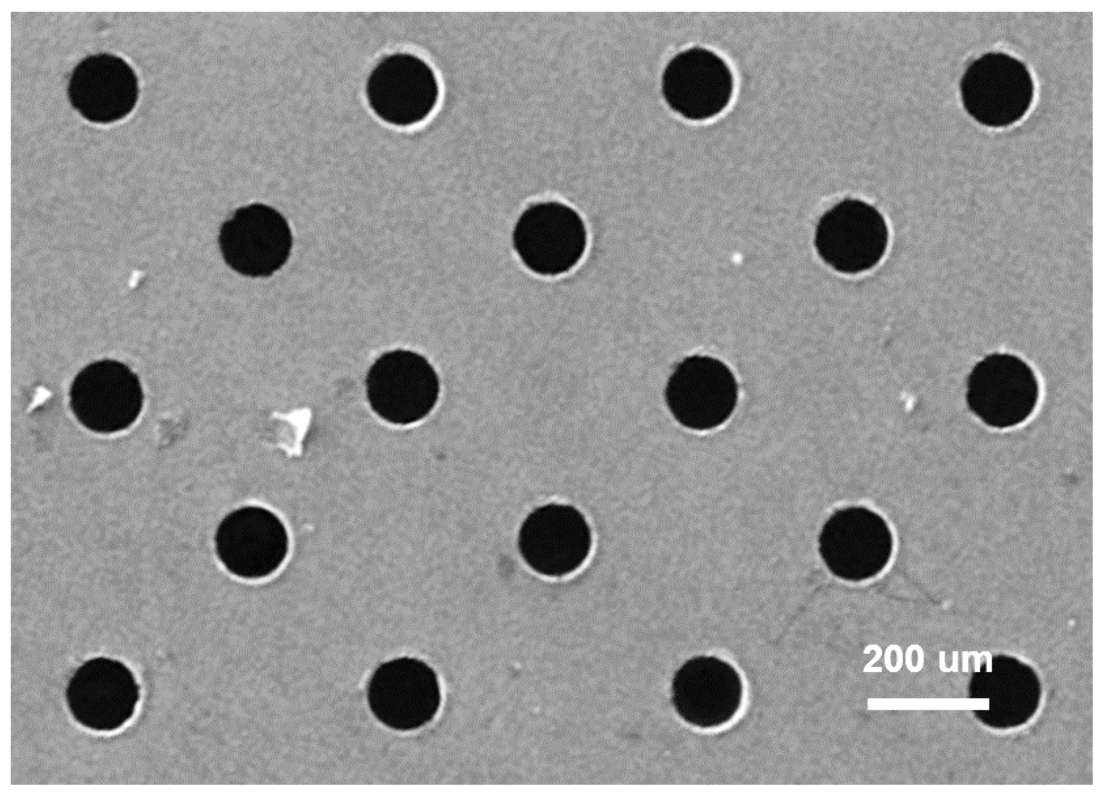
Cylindrical holes were drilled on the lapped surface using a micro-drill installed on a surface engraver machine (Roland EGX-350, Hamamatsu, Japan). The diameter of the holes (120 μm) was identical to that of the micro-drill bit, and the depth was adjusted to 300 μm, as shown in Figure 2. As well known, as the number of holes increases, more lubricant can be stored. However, the load-supporting capability simultaneously decreases. Our previous study [28] showed that a texturing fraction of more than 20% is undesirable in terms of reduced load-supporting capability, and a fraction lower than 10% is insufficient for capturing necessary lubricant. A very similar trend was observed from micro-machined POM (polyoxymethylene) specimen [29] despite the fact that the material used was not metal but polymer. Therefore, considering these two factors, 10% was chosen as a reasonable hole fraction in this study. The drilled holes appear dark in Figure 2, and bulges that formed during machining were also observed. Subsequently, the bulges were completely removed prior to anodization and wear tests.

2.3. Anodization of the Al Surface

A mirror-like surface with roughness of 0.01–0.02 μm Ra, as shown in Figure 1, was used because nanopores formed by anodization are extremely small. Otherwise, the nanopores are indiscernible or are not well formed. The structure and appearance of anodized surfaces depend on the chemical fluid, temperature, time, and voltage used [3]. In this study, oxalic acid was used to anodize the Al 6061 surface. According to a previous study [3], nanopores with a depth of 25 nm and a diameter of 35 nm and separated by 100 nm were formed when 0.3 M oxalic acid at 40 V was used. The same anodizing conditions as those used in Ref. [3] were applied to form nanopores in this study, which were subsequently used along with micro-holes to investigate the friction and wear behavior of Al 6061.
Figure 3a shows the FE-SEM (Carl Zeiss, SIGMA, Oberkochen, Germany) image of the surface after anodizing treatment under aforementioned conditions. It should be noted, however, that the appearance of the nanopores in this study is not identical to those in Ref. [3], and thus, the role of the nanopores would be different. Numerous tiny pores are well aligned with the wall-like nanostructures. If necessary, an auxiliary process known as widening treatment can also be used to obtain a nano-honeycomb structure. However, widening can make the walls thin, leading to the collapse of the nanostructure after the widening process. Figure 3b shows an example of the collapse of the nanostructure with widening treatment. The regular shape of the nanopores disappears after widening, and an amorphous rough structure is observed instead. Therefore, the anodized surfaces were used without further processing. In addition, since micro-holes were considered, widening to obtain the increased nanopores was not inevitably necessary despite lack of structural integrity.

2.4. Reciprocating Friction Test

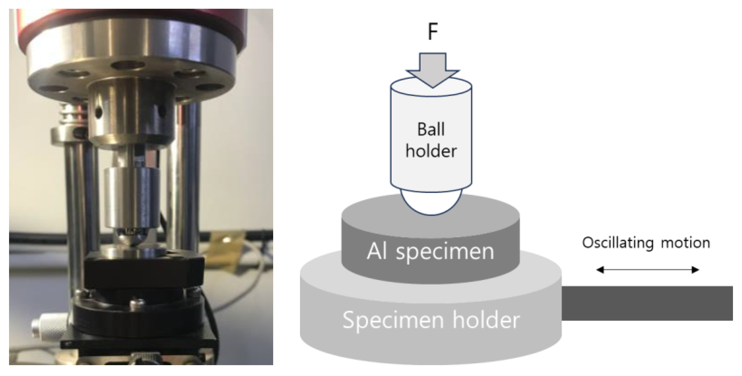
The friction and wear of the Al surfaces composed of micro-holes and/or nanopores were evaluated using a reciprocating tribometer (RFW 110, NEOPLUS Co., Daejeon, Korea). Figure 4 shows the tribometer used in this study and its ball-on-disk configuration. The diameter of the steel ball (AISI 52100) was 12.7 mm. SAE 5W-30 motor oil was used as a lubricant, and a drop of the lubricant (0.1 mL) was applied to the contact area using a micro-pipette (VOLAC). Before the reciprocating test, the air entrapped inside the holes was removed using a vacuum pump to help the lubricant soak in the nanopores.
To determine the applied load, the Hertz contact stress was calculated using a few load values. Among them, 1 N and 2 N loads were considered, and they yielded values of 158 and 316 MPa, respectively. These may cause severe surface damage during dry contact because they are greater than the ultimate tensile strength of Al. However, contact occurs under the lubricated state, which will greatly reduce surface damage. Therefore, if the applied load is low, no meaningful results can be obtained. Consequently, the load of 1 N was excluded, and 2 N was considered appropriate. A moderate frequency and travel distance of 2 Hz and 5 mm, respectively, were chosen to provide a sufficient contact length under a stable oscillating motion. One hour was used to reflect sufficient interactions at the oscillating interface.

3. Results

3.1. Friction and Wear of the Pristine Al Surface

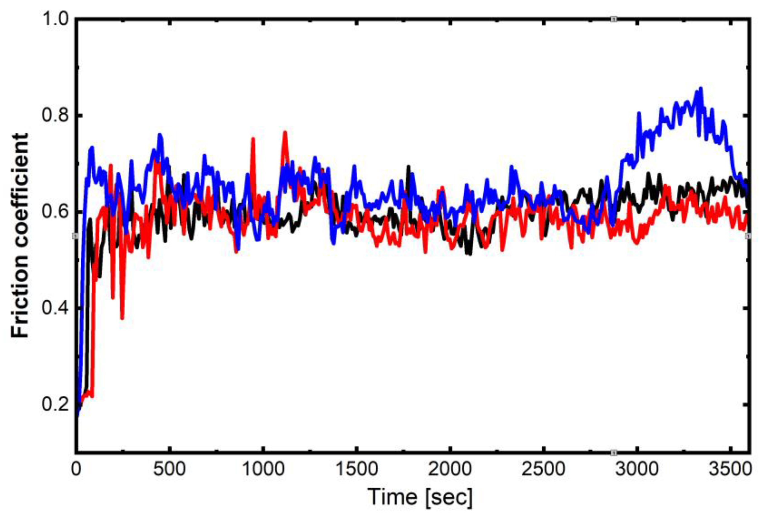
Figure 5 shows the coefficient of friction (c.o.f.) plots for the lapped pristine Al 6061 surface. The oscillating tests were repeated three times, and the average c.o.f. value was obtained from the steady state of each curve. The averaged final c.o.f. is approximately 0.61. Each curve significantly fluctuates during the oscillation motion, indicating lack of stability despite lubrication.
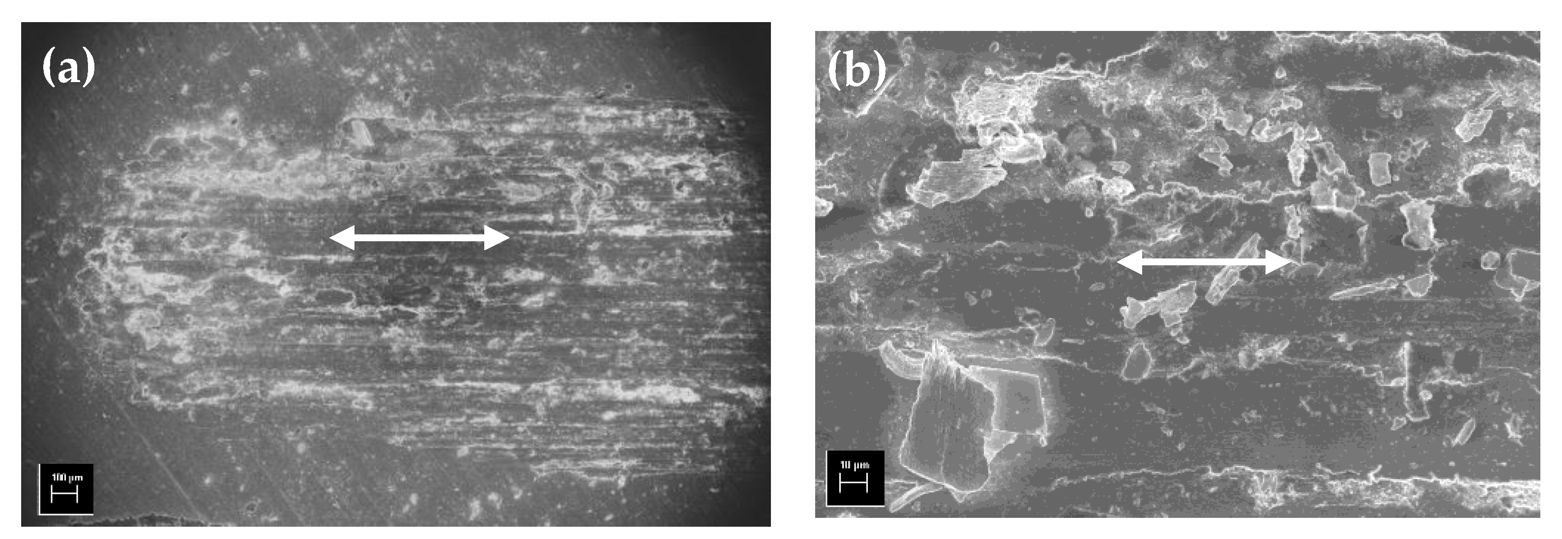
The worn area of the lapped surface is shown in Figure 6. The heavily rubbed surface is clearly shown in Figure 6a, where long and flat worn fragments adhere along the entire oscillating track. In addition, a lump of small worn debris accumulates at the track end. The magnified image in Figure 6b shows thin, layered, and plate-like wear debris, implying that abrasion was the major wear mechanism in this case. These results indicate that the wear and the c.o.f. of the pristine Al 6061 alloy specimen were high and unstable.

3.2. Friction and Wear of the Micro-Drilled Surface

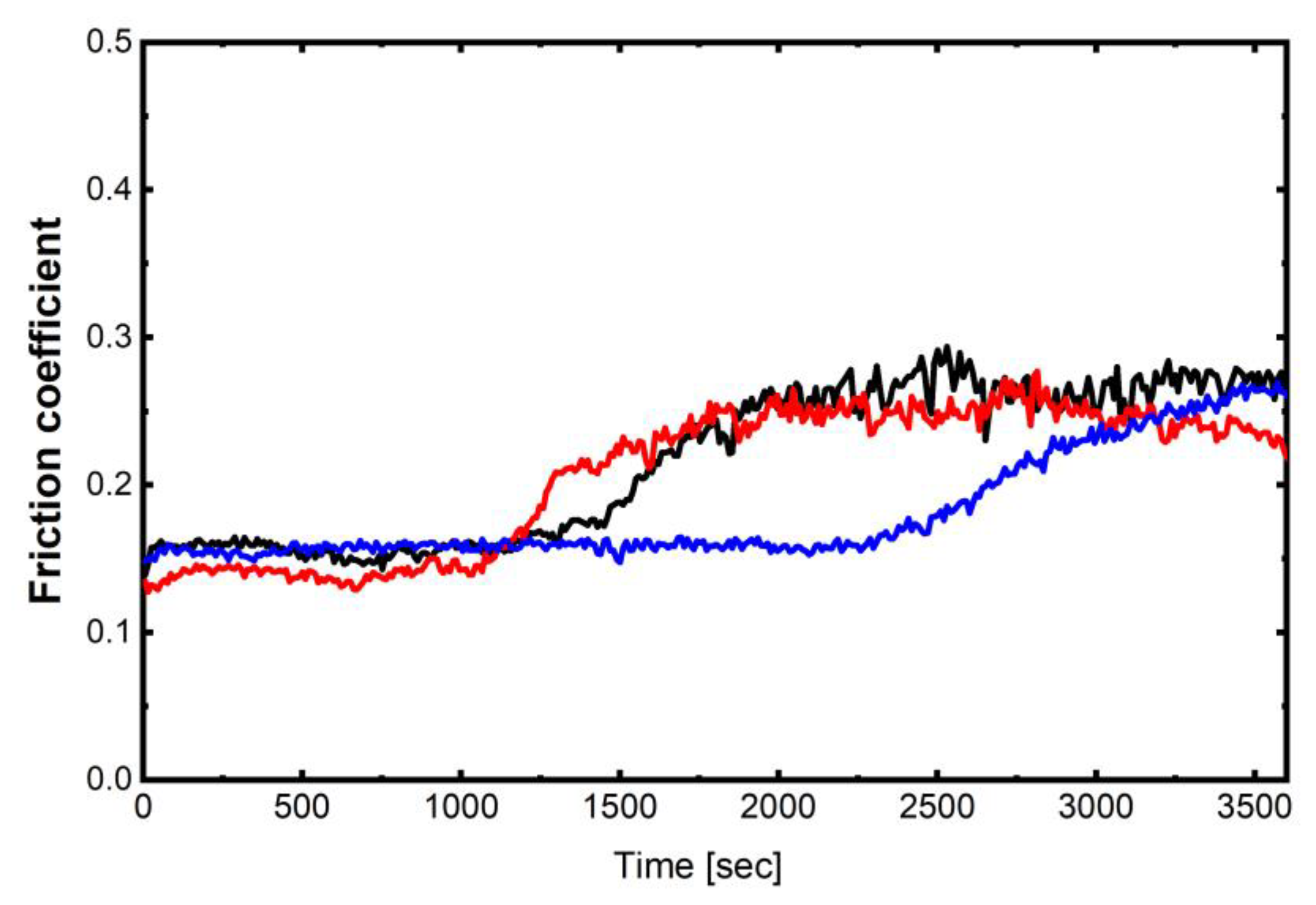
Figure 7 shows the c.o.f. of the micro-drilled Al alloy specimen. A stable friction coefficient of approximately 0.15 is initially maintained for at least 1000 s, but it increases with time and reaches approximately 0.23–0.28. Despite this increase, a significant reduction in the c.o.f. is evident when compared with that in Figure 5. The above results imply the effectiveness of micro-holes as lubricant reservoirs; unlike the pristine Al 6061 surface, the micro-holes supply lubricant and maintain low in the early stage of contact.
However, as shown Figure 7, the low friction state ceases with continued contact. As mentioned above, the c.o.f. almost doubles (approximately from 0.15 to 0.28). The worn track of the micro-drilled surface was investigated to determine the reason for the c.o.f. It was observed that the holes disappeared because of severe wear and damage. If the holes remain intact, the c.o.f. must remain low and stable. Therefore, the increase in friction can be attributed to the loss of lubricant supply capability owing to hole failure.
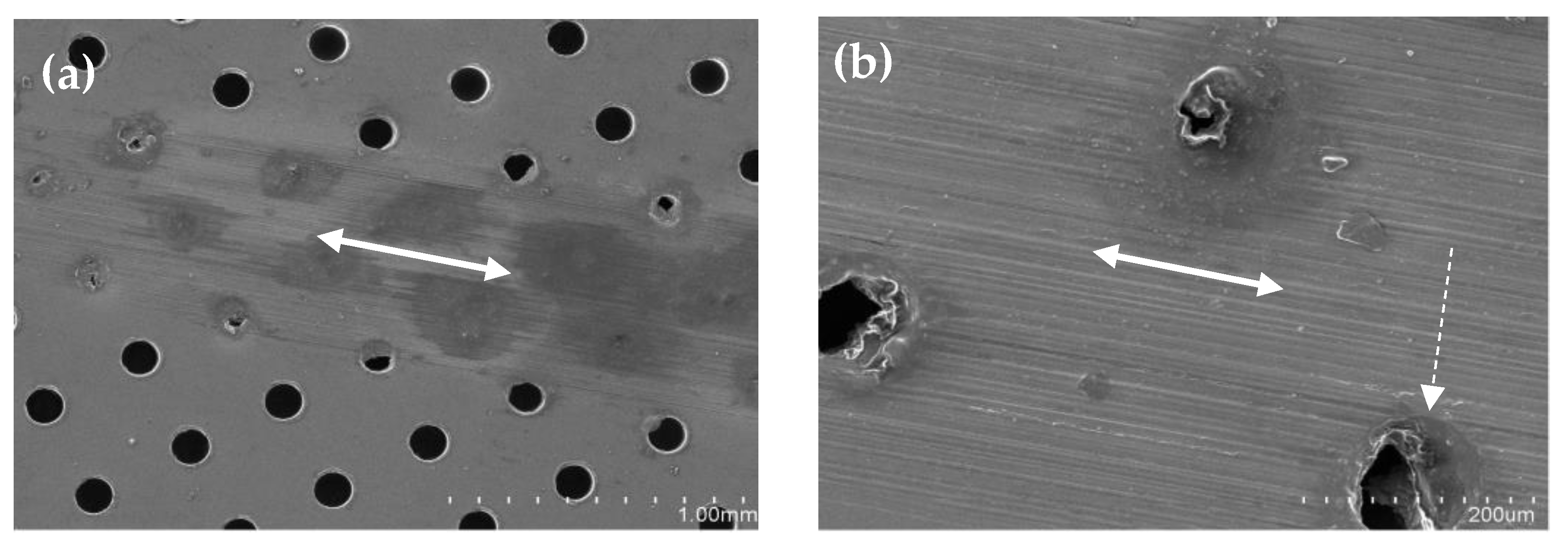
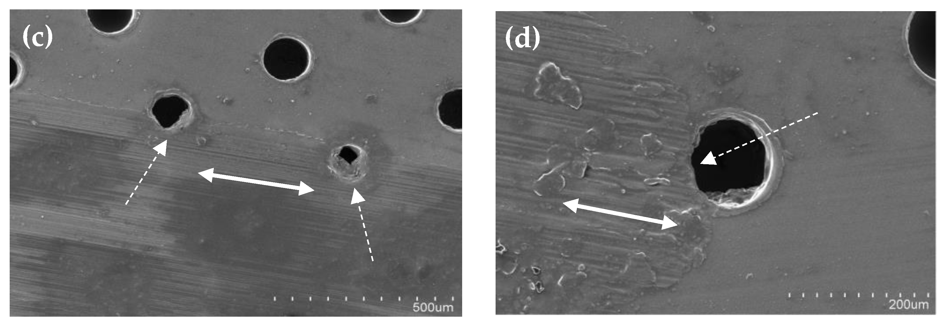
In general, the wear track of the micro-drilled surface was much smoother than that of the bare surface, although worn scratches were well developed along the micro-drilled surface. According to the Hertz contact theory, the contact radius under the ball contact is approximately 50 μm. However, the approximate width of the wear track shown in Figure 8a is definitely larger than 800 μm (that is, at least 15 times larger). This indicates a large growth in the contact area owing to wear with oscillating contact. The worn fragments may gradually fill the holes, as shown in Figure 8b, and finally the surface becomes flat with scratches. In some cases, the holes are partially covered by plastic shearing, as indicated by the dotted lines in Figure 8b–d. The lubricant retention capability is subsequently diminished. A thin sheared layer is also clearly seen along both the upper wear track and the track edge, as shown in Figure 8c,d, respectively. Compaction and attachment of the worn particles to the sled layer are clearly shown in Figure 8d.
As mentioned earlier, the contact stress exceeds the ultimate strength of Al 6061. Therefore, failure may be expected, particularly around the hole first, where stress concentrates. In conclusion, an important parameter is whether the micro-holes remain intact while the c.o.f. maintains low and stable.

3.3. Friction and Wear of Anodized Surface

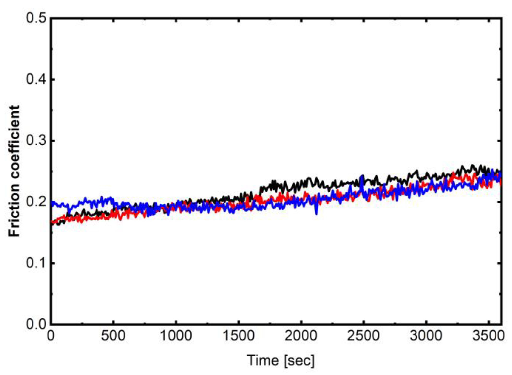
The c.o.f. of the anodized specimen as a function of the sliding time is shown in Figure 9. The c.o.f. was significantly reduced in the case of the anodization method. In addition, the variation amplitude in the friction curve during oscillating contact was reduced. These results indicate that the nanopores were remarkably effective in reducing friction, unlike the bare case. Such a remarkable reduction and stable behavior in the c.o.f. are presumed to originate from effective lubricant retention and timely supply of lubricant to the contact interface.
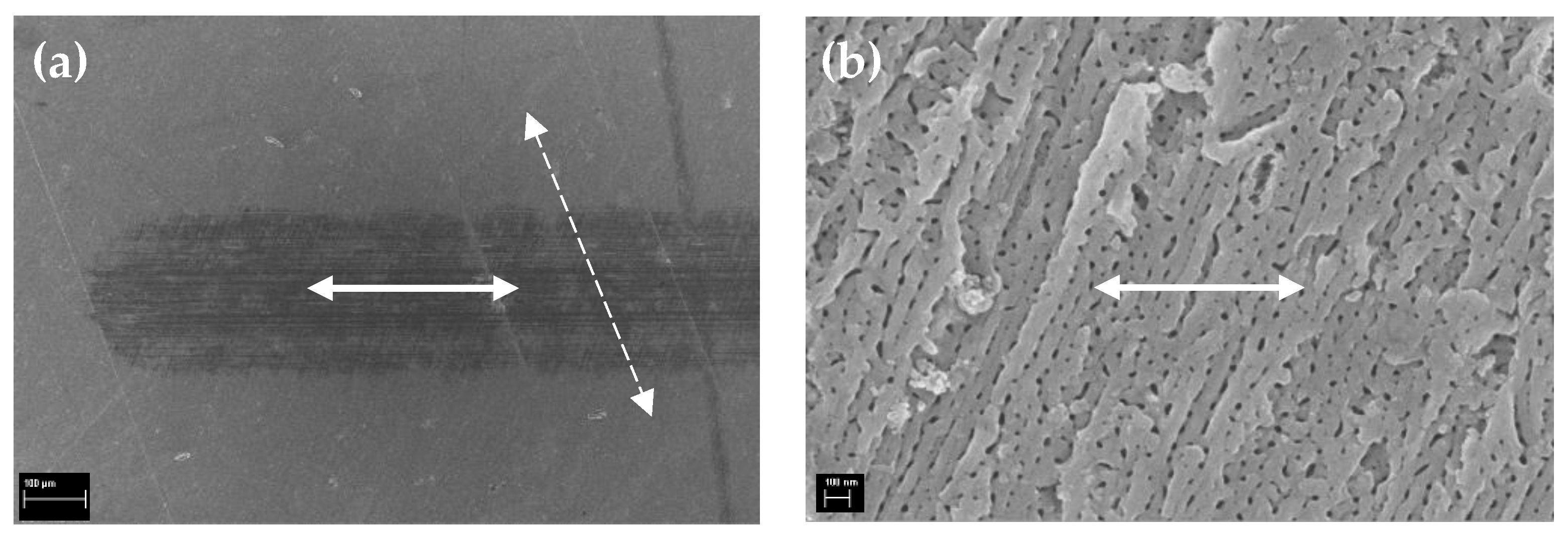
The increased hardness is expected to play an important role in maintaining the shape of the nanopores. A key advantage of anodization is the increased surface hardness owing to the formation of the Al oxide layer. It is necessary to investigate the anodized surface after oscillating to compare with the previous cases. Figure 10 shows the worn surface after the oscillating test. A dramatic change in the surface topography is observed, which appears significantly different from the pristine and micro-drilled surfaces. No deep or apparent wear scratches are observed along the wear tracks. Some furrows formed by finishing are visible behind the dark and worn area, indicating the formation of the shallow worn scratches. In addition, the width of the wear track shown in Figure 10a is approximately 250 μm, which is less than half of that of the textured case. This indicates a large reduction in wear owing to hardness enhancement. As shown in Figure 10b, an intact area of the nanopores was present even after the oscillating contact.
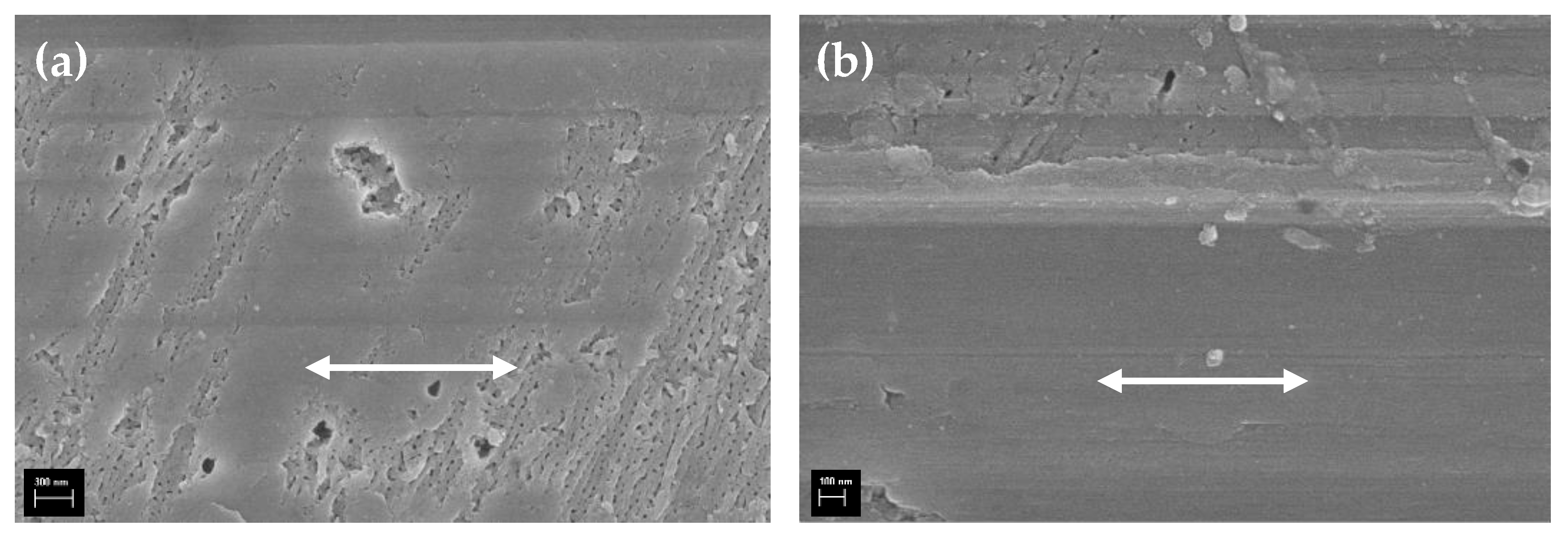
Figure 11a shows the coexistence of worn area and nanopores beneath the upper smooth layer. It clearly shows the nanopores on the surface even after a long repetitive oscillation. The lubricant can soak through the nanopores, thereby minimizing wear. These nanopores are observed throughout the worn surface. The formation of such a layered structure is because the anodized surface was not completely flat, as shown in Figure 10b. That is, the contact with the steel ball begins first at the elevated wall structures, and, as a result, the surface in Figure 11a formed. On the other hand, a highly flat and smooth surface containing the shallow worn scratches was also present, as shown in Figure 11b. These observations mean that a complicated contact interaction took place during the entire oscillation motion.
A worn surface layer formed at the track end is evident on the anodized surface, as shown in Figure 12a. It is highly likely that the worn fragments in the middle of the contact zone, where the contact pressure is the highest, were squeezed out toward the track edge that was normal and parallel to the oscillating direction. Therefore, the layer near the contact center was smoothened by repetitive compaction, while the worn debris consisting of various sizes was distributed along the wear track edge, as shown in Figure 12b. However, no large plate-like fragments as observed in Figure 6b were present, which indicates that abrasion was no longer a primary wear mechanism.

3.4. Friction and Wear of Hybrid Surface

As mentioned earlier, the hybrid surface consists of both micro-holes and nanopores on the lapped Al surface. Figure 13 shows the c.o.f. of the hybrid specimens. Unlike all the previous cases, the c.o.f. gradually decreases and reaches a steady-state value of approximately 0.15, which is slightly lower than that of the anodized specimen. It remains very stable and low, without fluctuation, until the end. This reduction in friction is presumably possible because of the synergistic behavior between the nanopores and micro-holes. The worn hybrid surface was examined to gain an insight into its excellent tribological performance.
The wear track of the hybrid specimen is shown in Figure 14a. The wear is so low that the wear track is almost invisible to the naked eye. Scratches along the wear track are rarely observed, and the holes on the wear track remain almost intact. Although an inappreciable failure is observed around some holes, the fragments do not cause third body abrasion. The fact that some debris was entrapped inside the hole, as indicated by the dotted lines in Figure 14a,b, supports our hypothesis. As shown in Figure 14c, a hole remained intact after oscillating contact. In addition, the nanostructure shown in Figure 14d is still present on the surface, although it is hidden by tiny particles.
Overall, the micro-drilled surface was anodized, and a strong oxide layer was formed on the surface, causing hardening. The early results confirmed that the non-anodized surface was weak and caused severe surface damage. In conclusion, the synergistic effect of introducing micro-holes should be accompanied by sufficient surface hardness from anodization, and then nanopores will promote the supplementary lubricating capability.

3.5. Hardness Measurement Results

Micro-Vickers hardness values were measured to investigate hardness variation owing to anodization, and the results are tabulated in Table 2. The force applied was 1 N. The hardness of the pristine Al and the anodized surface were approximately 112 HV and 193 HV, respectively, showing about 75% improvement. It should be noted, however, that the micro-drilled surface exhibited a lightly lower HV value than that of the pristine surface. This reduction in hardness is attributed to the easier and broader failure caused by the hard pyramidal indenter.

4. Discussion

The purpose of the surface texturing in this study was to demonstrate a synergistic effect by combining the micron-size texturing with the nanopores formed by anodization. Each element plays a distinct role: anodization contributes to hardness increase and lubricity improvement, while surface texturing helps lubricant storage capability and reduces third body abrasion. This study revealed that the coefficient of friction during early oscillation was low and stable. However, it increased as the textured holes were rubbed and eventually disappeared. Therefore, to achieve low and stable friction and wear behavior, the surface should be strong and hard enough. For this reason, the micro-Vickers hardness (DAM-315, DONG-AH Testing Machine, Seoul, Korea) of all specimens was measured to substantiate our hypothesis regarding wear resistance resulting from the hardening. Consequently, it can be concluded that the micro-texturing pattern alone is not correlated with the reduced wear of the Al surface. Instead, it is linked to the lubricant capture capability.

5. Conclusions

In this study, the synergistic effect of nanopores formed during anodization of Al when surface texturing is applied has been experimentally investigated. Anodizing Al can make its surface hard and strong, leading to wear resistance improvement. However, hard worn particles at the same time can cause severe abrasion. Therefore, reduction in third body abrasion was required in advance, and in that respect, surface texturing was adapted before anodizing Al to combine both nanopores and micron-sized holes. Reciprocating tests were carried out, and the following conclusions can be drawn from the present study.
  • The pristine Al 6061 alloy alone was highly vulnerable when exposed to light contact load conditions. The wear was very high, and a typical abrasive wear phenomenon was observed despite the lubricated oscillating environment. The coefficient of friction was significantly unstable throughout oscillating motion.
  • Micro-holes as a means of micro-texturing showed a substantial reduction in friction compared with that of the bare specimen. In addition, the friction behavior of the textured surface became stable. However, one of major drawbacks is the collapse of the micro-holes during oscillating, leading to the loss of lubricant retention capability. Thus, it is concluded that the increase in friction is closely related to the collapse of the micro-holes. If an area contact instead of a ball contact is introduced, the textured holes would be highly efficient in reducing friction and wear of the Al alloy.
  • Anodization of Al was found to be significantly effective in reducing friction and wear by forming a hard and strong alumina layer on its surface. These results were consistent with those of other relevant studies. The friction decreased and maintained stability throughout the entire oscillation duration.
  • Furthermore, the best enhancement of tribological performance was achieved by combining both nanopores and micro-holes. The surface hardness was effectively increased by anodization, and, consequently, the wear significantly decreased. Based on the hardened surface, the micro-holes can contain more lubricant and effectively supply it to the interface. In conclusion, a synergistic advantage in terms of tribology is possible only when the wear-resistive surface prepared by anodization is well lubricated with the help of nano- and micro-surface structures.
  • Although tribological characteristics of the hybrid surface were considerably improved, the results shown in this work are based on a limited sliding condition and texturing fraction. To broaden its applicability, additional experimental work is currently underway, in particular exploring a wider range of texturing fractions, loads, and oscillating frequencies.

Funding

This research received no external funding.

Data Availability Statement

No new data were created or analyzed in this study. Data sharing is not applicable to this article.

Acknowledgments

The author would like to thank Jeong, Junho in Kumho Tire Co. for performing the experiments mentioned in this manuscript.

Conflicts of Interest

The author declares no conflict of interest.

References

  1. Masuda, H.; Fukuda, K. Ordered metal nanohole arrays made by a two-step replication of honeycomb structures of anodic alumina. Science 1995, 268, 1466–1468. [Google Scholar] [CrossRef] [PubMed]
  2. Takaya, M.; Hashimoto, K.; Toda, Y.; Maejima, M. Novel tribological properties of anodic oxide coating of aluminum impregnated with iodine compound. Surf. Coat. Technol. 2003, 169–170, 160–162. [Google Scholar] [CrossRef]
  3. Lee, G.S.; Choi, J.H.; Choi, Y.C.; Bu, S.D.; Lee, Y.Z. Tribological effects of pores on an anodized Al alloy surface as lubricant reservoir. Curr. Appl. Phys. 2011, 11, S182–S186. [Google Scholar] [CrossRef]
  4. Tu, J.P.; Jiang, C.X.; Guo, S.Y.; Fu, M.F.; Zhao, X.B. Friction and wear properties of aligned film of amorphous carbon nanorods on anodic aluminum oxide template in vacuum. Surf. Coat. Technol. 2005, 198, 464–468. [Google Scholar] [CrossRef]
  5. Tu, J.P.; Jiang, C.X.; Guo, S.Y.; Zhao, X.B.; Fu, M.F. Tribological properties of aligned film of amorphous carbon nanorods on AAO membrane in different environments. Wear 2005, 259, 759–764. [Google Scholar] [CrossRef]
  6. Poznyak, A.; Knornschild, G.; Karoza, A.; Norek, M.; Pligovka, A. Peculiar Porous Aluminum Oxide Films Produced via Electrochemical Anodizing in Malonic Acid Solution with Arsenazo-I Additive. Materials 2021, 14, 5118. [Google Scholar] [CrossRef] [PubMed]
  7. Rawian, N.A.M.; Akasaka, H.; Liza, S.; Fukuda, K.; Zulkifli, N.A.; Tahir, N.A.M.; Yaakob, Y. Surface and tribological characterization of anodic aluminum oxide coating containing diamond-like carbon flakes. Diam. Relat. Mater. 2023, 132, 109674. [Google Scholar] [CrossRef]
  8. Sundararajan, M.; Devarajan, M.; Jaafar, M. A novel sealing and high scratch resistant nanorod Ni-P coating on anodic aluminum oxide. Mater. Lett. 2021, 289, 129425. [Google Scholar] [CrossRef]
  9. Kim, Y.J.; Kim, H.J. Study on tribological behavior of porous anodic aluminum oxide with respect to surface coating. J. Korean Soc. Tribol. Lubr. Eng. 2017, 33, 275–281. [Google Scholar]
  10. Zhou, Y.; Zhu, H.; Tang, W.; Ma, C.; Zhang, W. Development of the theoretical model for the optimal design of surface texturing on cylinder liner. Tribol. Int. 2012, 52, 1–6. [Google Scholar] [CrossRef]
  11. Wang, X.; Kato, K.; Adachi, K.; Aizawa, K. Loads carrying capacity map for the surface texturing design of SiC thrust bearing sliding in water. Tribol. Int. 2003, 36, 189–197. [Google Scholar] [CrossRef]
  12. Ryk, G.; Etsion, I. Testing piston rings with partial laser surface texturing for friction reduction. Wear 2006, 261, 792–796. [Google Scholar] [CrossRef]
  13. Li, J.; Xiong, D.; Dai, J.; Huang, Z.; Tyagi, R. Effect of surface laser texture on friction properties of nickel-based composite. Tribol. Int. 2010, 43, 1193–1199. [Google Scholar] [CrossRef]
  14. Petterson, U.; Jacobson, S. Influence of surface texture on boundary lubricated sliding contacts. Tribol. Int. 2003, 36, 857–864. [Google Scholar] [CrossRef]
  15. Anderson, P.; Koskinen, J.; Varjus, S.; Gerbig, Y.; Haefke, H.; Georgiou, S.; Zhmud, B.; Buss, W. Microlubrication effect by laser-textured steel surfaces. Wear 2007, 262, 369–379. [Google Scholar] [CrossRef]
  16. Cho, M.H. Friction and wear of a hybrid surface texturing of polyphenylene sulfide-filled micropores. Wear 2016, 346–347, 158–167. [Google Scholar] [CrossRef]
  17. Costa, H.L.; Hutchings, I.M. Hydrodynamic lubrication of textured steel surfaces under reciprocating sliding conditions. Tribol. Int. 2007, 40, 1227–1238. [Google Scholar] [CrossRef]
  18. Wang, X.; Kato, K.; Adachi, K.; Aizawa, K. The effect of laser texturing of SiC surface on the critical load for the transition of water lubrication mode from hydrodynamic to mixed. Tribol. Int. 2001, 34, 703–711. [Google Scholar] [CrossRef]
  19. Mourier, L.; Mazuyer, D.; Lubrecht, A.A.; Donnet, C. Transient increase of film thickness in micro-textured EHL contacts. Tribol. Int. 2006, 39, 1745–1756. [Google Scholar] [CrossRef]
  20. Moshkovith, A.; Perfiliev, V.; Gindin, D.; Parkansky, N.; Boxman, R.; Rapport, L. Surface texturing using pulsed air arc treatment. Wear 2007, 263, 1467–1469. [Google Scholar] [CrossRef]
  21. Wakuda, M.; Yamauchi, Y.; Kanzaki, S.; Yasuda, Y. Effect of surface texturing on friction reduction between ceramic and steel materials under lubricated sliding contact. Wear 2003, 254, 356–363. [Google Scholar] [CrossRef]
  22. Borghi, A.; Gualtieri, E.; Marchetto, D.; Moretti, L.; Valeri, S. Tribological effect of surface texturing on nitriding steel for high-performance engine applications. Wear 2008, 265, 1046–1051. [Google Scholar] [CrossRef]
  23. Vilhena, L.M.; Sedlacek, M.; Podgornik, B.; Vizintin, J.; Babnik, A.; Mozina, J. Surface texturing by pulsed Nd:YAG laser. Tribol. Int. 2009, 42, 1496–1504. [Google Scholar] [CrossRef]
  24. Rumiche, F.; Wang, H.H.; Hu, W.S.; Indacochea, J.E.; Wang, M.L. Anodized aluminum oxide (AAO) nanowell sensors for hydrogen detection. Sens. Actuators B Chem. 2008, 134, 869–877. [Google Scholar] [CrossRef]
  25. Preston, C.K.; Moskovits, M. Optical characterization of anodic aluminum oxide films containing electrochemically deposited metal particles. 1. Gold in phosphoric acid anodic aluminum oxide films. J. Phys. Chem. 1993, 97, 8495–8503. [Google Scholar] [CrossRef]
  26. Brevnov, D.A.; Barela, M.J.; Brooks, M.J.; Lopez, G.P.; Atanassov, P.B. Fabrication of anisotropic super hydrophobic/hydrophilic nanoporous membranes by plasma polymerization of C4F8 on anodic aluminum oxide. J. Electrochem. Soc. 2004, 151, B484–B489. [Google Scholar] [CrossRef]
  27. Li, F.; Zhang, L.; Metzger, R.B. On the growth of highly ordered pores in anodized aluminum oxide. Chem. Mater. 1998, 10, 2470–2480. [Google Scholar] [CrossRef]
  28. Jeong, J.H.; Cho, M.H. Tribological characteristics of anodized Al 6061 under deionized water lubricated reciprocating condition. J. Korean Soc. Tribol. Lubr. Eng. 2017, 33, 59–64. [Google Scholar]
  29. Cho, M.H.; Park, S.I. Micro CNC surface texturing on polyoxymethylene (POM) and its tribological performance in lubricated sliding. Tribol. Int. 2011, 44, 859–867. [Google Scholar] [CrossRef]
Figure 1. (a) Al disk surface after lapping. (b) Three-dimensional surface topography: 0.01–0.02 μm Ra. Scan area: 620 × 464 μm.
Lubricants 11 00533 g001
Figure 2. Observation of micro-holes formed by a micro-drill on the lapped surface. The diameter and depth are 120 μm and 300 μm, respectively.
Lubricants 11 00533 g002
Figure 3. FE-SEM image of (a) nanopores and wall structure formed by anodization; (b) collapse of the nanostructure after widening treatment.
Lubricants 11 00533 g003
Figure 4. Reciprocating friction test setup and its configuration. Oscillation test conditions: frequency 2 Hz, travel distance 5 mm, normal load F = 2 N, and duration 1 h.
Lubricants 11 00533 g004
Figure 5. Variation in the c.o.f. of the pristine Al alloy specimen as a function of the sliding time. Oscillating test conditions are given in Figure 4. Red, blue, and black denote each test result throughout the friction vs. time plots.
Lubricants 11 00533 g005
Figure 6. FE-SEM image of (a) an edge of the oscillating end and (b) small flat and plate-like worn debris. The solid double-arrow indicates the oscillating direction. Oscillating test conditions are given in Figure 4. The scale bars correspond to 100 μm and 10 μm, respectively.
Lubricants 11 00533 g006
Figure 7. Variation in the c.o.f. of the micro-drilled specimen as a function of the sliding time. Oscillating test conditions are given in Figure 4. Red, blue, and black denote each test result.
Lubricants 11 00533 g007
Figure 8. SEM image of worn surface after the oscillating test. (a) Wear track, (b) worn and filled holes, (c) sheared layer along the upper wear track, (d) compaction of worn particles at the track edge. The solid double-arrow indicates the oscillating direction. The dotted lines indicate the partially covered holes.
Lubricants 11 00533 g008aLubricants 11 00533 g008b
Figure 9. Variation in the c.o.f. of the anodized specimen as a function of the sliding time. Oscillating test conditions are given in Figure 4. Red, blue, and black denote each test result.
Lubricants 11 00533 g009
Figure 10. FE-SEM image of worn surface of the anodized specimen after oscillating. (a) Wear track and (b) nanopores over the wear track. The solid double-arrow indicates the oscillating direction. The dotted arrow corresponds to the finishing direction. The scale bars correspond to 100 μm and 100 nm, respectively.
Lubricants 11 00533 g010
Figure 11. FE-SEM image of worn surface of the anodized specimen after oscillating. (a) The coexistence of worn area and the nanopores and (b) a highly rubbed and pressed surface. The solid double-arrow indicates the oscillating direction. The scale bar corresponds to 300 nm and 100 nm, respectively.
Lubricants 11 00533 g011
Figure 12. FE-SEM image of (a) right edge of the wear track and (b) nanopores and wear debris near the wear track, which are from the white rectangle in the (a) image. The solid double-arrow indicates the oscillating direction. The scale bar corresponds to 10 μm and 100 nm, respectively.
Lubricants 11 00533 g012
Figure 13. Variation in the c.o.f. of the hybrid surface as a function of the sliding time. Oscillating test conditions are given in Figure 4. Red, blue, and black denote each test result.
Lubricants 11 00533 g013
Figure 14. Fe-SEM image of worn surface of the hybrid surface. (a) Wear track, (b) a hole filled with worn fragments, (c) a hole in intact state, and (d) nanopores underneath the wear debris. The solid double-arrow indicates oscillating direction. The dotted arrows indicate partially filled holes. The scale bars correspond to 100 μm, 20 μm, 10 μm, and 100 nm, respectively.
Lubricants 11 00533 g014
Table 1. The chemical constituents of the Al 6061 alloy by weight percent.
ElementComposition, wt.%
Silicone04–0.8
Iron~0.7
Copper0.15–0.4
Manganese~0.15
Magnesium0.8–1.2
Chromium~0.25
Zinc0.04–0.35
Titanium~0.15
AluminumRemainder
Table 2. Vickers hardness measurement results. The measurements were conducted in triplicate, and the average values are also presented. Applied load 1 N, the dwell time 15 s.
TypeBare SurfaceAnodized Surface
1st107.7199.3
2nd108.9189.2
3rd121.2189
Avg.112.6192.5
Disclaimer/Publisher’s Note: The statements, opinions and data contained in all publications are solely those of the individual author(s) and contributor(s) and not of MDPI and/or the editor(s). MDPI and/or the editor(s) disclaim responsibility for any injury to people or property resulting from any ideas, methods, instructions or products referred to in the content.