Article

Study on Sealing Characteristics of Compliant Foil Face Gas Seal under Typical Hypervelocity Gas Effects

1
College of Mechanical Engineering, Zhejiang University of Technology, Hangzhou 310032, China
2
College of Mechanical and Electrical Engineering, China Jiliang University, Hangzhou 310018, China
*
Author to whom correspondence should be addressed.
Lubricants 2023, 11(2), 46; https://doi.org/10.3390/lubricants11020046
Submission received: 14 December 2022 / Revised: 15 January 2023 / Accepted: 19 January 2023 / Published: 28 January 2023
(This article belongs to the Special Issue Dynamics of Lubricated Interfaces)

Abstract

:
In order to investigate the influence of typical hypervelocity gas effects on the gas lubrication performance of compliant foil face gas seal (CFFGS) end surfaces, the gas–elastic coupling lubrication theory model of CFFGS is modified by considering the choked flow and inertia effect, and the lubrication performance is solved using the finite difference method. Based on the choking effect, the effect of hypervelocity choked flow on the pressure field and velocity field of the seal is analyzed, and the influence of operating parameters on the choked flow and the mechanism of choked flow on the change in dynamic lubrication and sealing performance are explored. Furthermore, based on the inertia effect, the effect of gas inertia force on the flow field, and the correlation law between the pressure field and velocity field under the influence of operating parameters are studied. Then, the relationship between the inertia effect and sealing performance are analyzed. The results show that choked flow increases sealing outlet pressure significantly, from 0.1 MPa to a maximum of 14.25 MPa, and the sealing outlet flow velocity decreases by up to 50 times. The increase in medium pressure and balance film thickness aggravate the choking effect, resulting in a 20% maximum increase in opening force and a 99.6% maximum decrease in leakage rate. In addition, the inertia effect causes obvious centrifugal movement of the gas flow. As result, the radial flow velocity reduces by up to 50%, and the pressure distribution varies widely. Especially under high rotational speed and high medium pressure, the inertia effect is enhanced to clearly reduce the opening force (max. decrement of 3.5%) and leakage rate (max. decrement of 23%).

Graphical Abstract

1. Introduction

End face gas seal is based on the principle of the dynamic and static pressure of gas, forming a layer of micron-thick gas film at the dynamic sealing interface, to realize the non-contact operation of the dynamic seal and achieve the effect of sealing and lubrication [1]. At present, end face gas seal is widely used in the shaft end seal of turbomachinery by virtue of its low leakage, long life, and wear-free characteristics [2]. However, with the development of turbine mechanical power transmission systems to high speed, sealing technology has been pushed to the limit of performance [3]. Under extreme operating conditions such as high rotating speed and high medium pressure, the rigid surface of end face gas seal is prone to rubbing and crushing. Compliant foil face gas seal (CFFGS) with gas as the lubricating medium shows important application value in the shaft end seal of centrifugal compressors, aero-engines, and other turbomachinery, with its significant advantages such as high temperature resistance, impact resistance, excellent leakage control, and strong adaptability [4,5].
Gas foil bearing is a kind of aerodynamic bearing characterized by foil as the elastic support, which realizes non-contact bearing and lubrication by generating gas film through smooth top foils [6]. It has important application value in high-speed turbomachinery owing to its higher reliability, lower operating costs, and soft failure, etc. [7]. In 1982, Heshmat [8] proposed the design structure of the compliant gas foil thrust bearing, and verified its performance experimentally. Subsequent scholars continued to carry out in-depth theoretical and experimental research on this bearing, and applied it to engineering practice, showing significant performance advantages under high-speed and wide temperature-range conditions. Therefore, at the beginning of the 21st century, Heshmat [9] and Agrawal [10] put forward the structural design of compliant foil cylindrical and face gas seals with flexible foil support based on the successful application technology experience of gas foil bearing. Muson et al. [11,12] verified that CFFGS has excellent adaptability and leakage control performance under extremely highspeed and high-temperature conditions. The test results of Heshmat et al. [4,13] based on aircraft air circulation machines and hydrogen centrifugal compressors show that CFFGS is a high-efficiency gas sealing technology with low leakage and low wear. Research by Muson [5] shows that CFFGS has important applications in turbine shaft-end seals. Bai [14] and Zhao [15] also analyzed the mechanical properties of compliant foil cylindrical gas seal. Based on the gas–elastic coupling analysis method, Chen et al. [16,17] carried out sealing performance evaluation and structural optimization of CFFGS. Wang et al. [18] applied the small perturbation method for dynamic performance prediction and dynamical structure optimization of CFFGS. Based on the fluid–solid coupling analysis method, Sun et al. [19] explored the static characteristics of compliant foil gas seal and the mechanical properties of its supporting structures under different operating parameters. Wang et al. [20,21] studied the effects of structural and operating parameters on steady-state sealing performance and gas film dynamic characteristics of compliant foil gas seal.
At present, the research system and experimental system of gas foil bearing tend to be perfected and have been widely used in high-end rotating power equipment. CFFGS has similar geometry and operating principles to gas foil bearing, thus, the research in the field of gas foil bearing can provide corresponding reference theory for CFFGS. However, the operating characteristics of CFFGS are different from those of gas foil bearing in some aspects, so their own characteristics should be taken into account rather than copying the research model of gas foil bearing. Firstly, CFFGS needs to withstand the medium pressure difference between the inner and outer radius, which will have an impact on the lubrication flow field and the mechanical properties of the foil. Secondly, the gas film floating range of the gas foil bearing can reach several tens of microns, while CFFGS needs to consider the sealing. Thus, in order to control the leakage, the fluctuation range of the gas film thickness needs to be strictly controlled, so it has high requirements in terms of stability and sealing. As a new type of end face gas seal, the patented structure of CFFGS was first published just over ten years ago. Currently, although some scholars have carried out experiments to verify its good application value, there is still little literature available for reference. Additionally, in recent years, some scholars have carried out analysis of CFFGS’s flow field and the evaluation of foil mechanical properties, but few scholars have carried out hypervelocity gas effect research on CFFGS. However, with the development of turbomachinery to ultra-high speed and high-pressure conditions, the choked flow and inertia effect of hypervelocity gas flow between CFFGS’s seal faces has become prominent, which will have an impact on the design of high-parameter CFFGS. Therefore, it is of great significance to carry out research on the hypervelocity gas effects of CFFGS to improve the CFFGS research system. At present, research related to the hypervelocity choked flow and inertia effect of dry gas seal and gas thrust bearing has been carried out by scholars. In 1971, Zuk et al. [22,23] studied the phenomenon of high-speed gas flow in smooth surface pump-out face seal. The results showed that the supersonic flow of gas under high pressure had a choking effect, leading to the leakage rate not changing with the pressure. Arghir et al. [24] analyzed the static characteristics of annular seal under the condition of choked flow, revealing that the seal outlet is prone to choking and the static stiffness of the gas film will change. Thomas et al. [25,26] carried out research based on a conical face gas seal, which revealed that choked flow makes the pressure at the sealing outlet higher than the ambient pressure, and the leakage rate reaches its maximum at the same time. Thatte et al. [27] studied the flow field distribution of DGS based on the choked flow condition. Pinkus et al. [28] found that the inertia effect will lead to cavitation in the lubricating gas film of thrust bearing and face seal, resulting in reduced performance, and structural designs have been proposed to reduce the negative effects of inertia force. Yu et al. [29] pointed out that the gas inertia force will change the flow trend and reduce the load-carrying performance. Thomas et al. [21,22] studied the thermal elastohydrodynamic lubrication characteristics of high-pressure gas face seal based on the inertia effect and choking effect. Garrat et al. [30] analyzed the flow field distribution characteristics of incompressible flow based on the gas inertia effect, and the results show that the inertia force is the most prominent at the wedge gap. The research of Fariuz et al. [31] shows that the inertia effect will significantly reduce DGS’s load-carrying capacity and leakage rate. Xu [32], Shen [33], and Yang [34] have also carried out relevant research on the influence of gas inertia force on the stability and dynamic performance of the DGS. In summary, for dry gas seals and gas thrust bearings, the above results show that the supersonic gas flow caused by high rotating speed and high pressure will generate choked flow, which makes the seal outlet pressure higher than the ambient pressure. At this time, the leakage rate and opening force obtained by using the mandatory outlet pressure boundary will deviate from the actual situation. Moreover, the inertia effect of hypervelocity gas flow will change the flow field distribution of the end face, and then affect the seal’s load-carrying performance and leakage control performance. However, for CFFGS, the sealing characteristics considering the choked flow and inertia effect remain unclear, which restricts the research and design of high-parameter CFFGS. Therefore, further research on the choked flow and inertia effect of CFFGS is indispensable. This paper aims to study the gas choking effect and inertia effect of high speed and high pressure CFFGS, to clarify the operating conditions under which the choking and inertia effect should be considered, to investigate the mechanism of the choking and inertia effect on the pressure distribution and velocity distribution of the end face gas, and to analyze the variation law of sealing performance under different degrees of the choking and inertia effect by the relevant mechanism. Finally, it will provide a reference for the theoretical research and engineering design of CFFGS.
In this paper, a CFFGS gas–elastic coupling lubrication theoretical model is established, and the lubrication theoretical model is modified by considering the choked flow and inertia effect of hypervelocity gas flow. The distribution law of the pressure field and velocity field of the sealing face under the ignorance and consideration of choked flow is compared and analyzed, the relationship between operating parameters and choked flow is explored, and the impact of choked flow on the dynamic lubrication and sealing performance under the influence of operating parameters is explored. Under the condition of considering choked flow, the influence of the inertia effect on the flow trend of the flow field is further explored based on the inertia effect of hypervelocity gas flow. The mechanism of the inertia effect on the pressure field and velocity field and the change law of sealing performance under different operating conditions are analyzed to provide a reference for the theoretical research and engineering design of CFFGS. The above study is of great significant and can provide a theoretical reference for the establishment of CFFGS’s fluid lubrication and numerical solution model modified by the hypervelocity gas effects. In addition, this study reveals the mechanism of the choked flow and inertia effect on the lubrication flow field and sealing performance, filling the gap in the study of hypervelocity gas effects on CFFGS. Furthermore, it will provide theoretical guidance for the research, design, and performance prediction of high-parameter CFFGS.

2. Theoretical Model

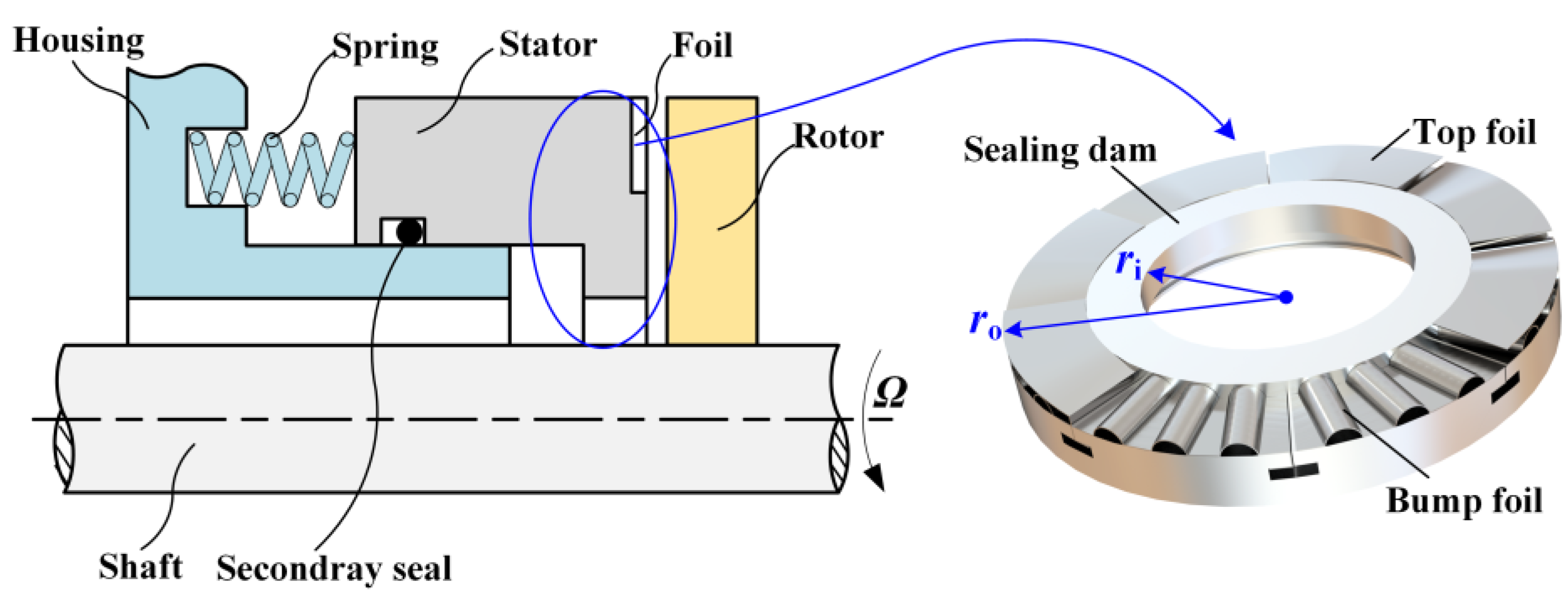
2.1. Structure of CFFGS

Figure 1 is a structural diagram of compliant foil face gas seal (CFFGS) [17]. As is shown, the elastic supporting structure of CFFGS is evenly arranged on the outside of the stator by the bump foil and the top foil along the circumferential direction. The inclined section of the top foil forms a convergent gap with the rotor, and the inside of the stator is a sealing dam. When the rotor rotates at high speed, the rotor and stator move relative to the direction of convergent gap reduction. Then, the gas between the end faces is squeezed into the convergent gap to produce a hydrodynamic effect so that the rotor and stator are pushed apart and a layer of micron-thick lubricating gas film is formed. Moreover, in response to changes in the operating environment, the elastic supporting structure of CFFGS can be adjusted through elastic deformation to achieve high stability and adaptive operation [18].

2.2. Control Equation of Film Pressure

It is assumed that the lubricating fluid is an ideal isothermal and isoviscous gas, and is in a laminar flow state. The steady-state Reynolds equations neglecting and considering the inertia effect correction in cylindrical coordinates are shown in Equations (1) and (2), respectively [32,34].
θ ( p h 3 p θ ) + r r ( r p h 3 p r ) = 6 μ Ω r 2 ( p h ) θ
θ ( p h 3 p θ ) + r r ( r p h 3 p r ) = 6 μ Ω r 2 ( p h ) θ + 3 Ω 2 r 10 R g T ( p 2 r 2 h 3 ) r
where p is film pressure, h is film thickness, r is radius, θ is circumferential angle, μ is gas viscosity, Ω is angular velocity of shaft, Rg is gas constant, and T is temperature.
To facilitate analysis, dimensionless variables are defined as follows:
P = p p a ; H = h h d ; R = r r i ; Λ 1 = 6 μ Ω r i 2 p a h d 2 ; Λ 2 = 3 Ω 2 r i 2 10 R g T
where P is dimensionless film pressure, H is dimensionless film thickness, R is dimensionless radius, Ʌ1 is compressibility number, and Ʌ2 is the coefficient of inertia term.
Then, dimensionless steady-state Reynolds equations neglecting and considering the inertia effect correction are shown in Equations (4) and (5), respectively.
R θ ( H 3 R P 2 θ ) + R R ( R H 3 P 2 R ) = 2 Λ 1 ( P H ) θ
R θ ( H 3 R P 2 θ ) + R R ( R H 3 P 2 R ) = 2 Λ 1 ( P H ) θ + 2 Λ 2 1 R ( P 2 R 2 H 3 ) R

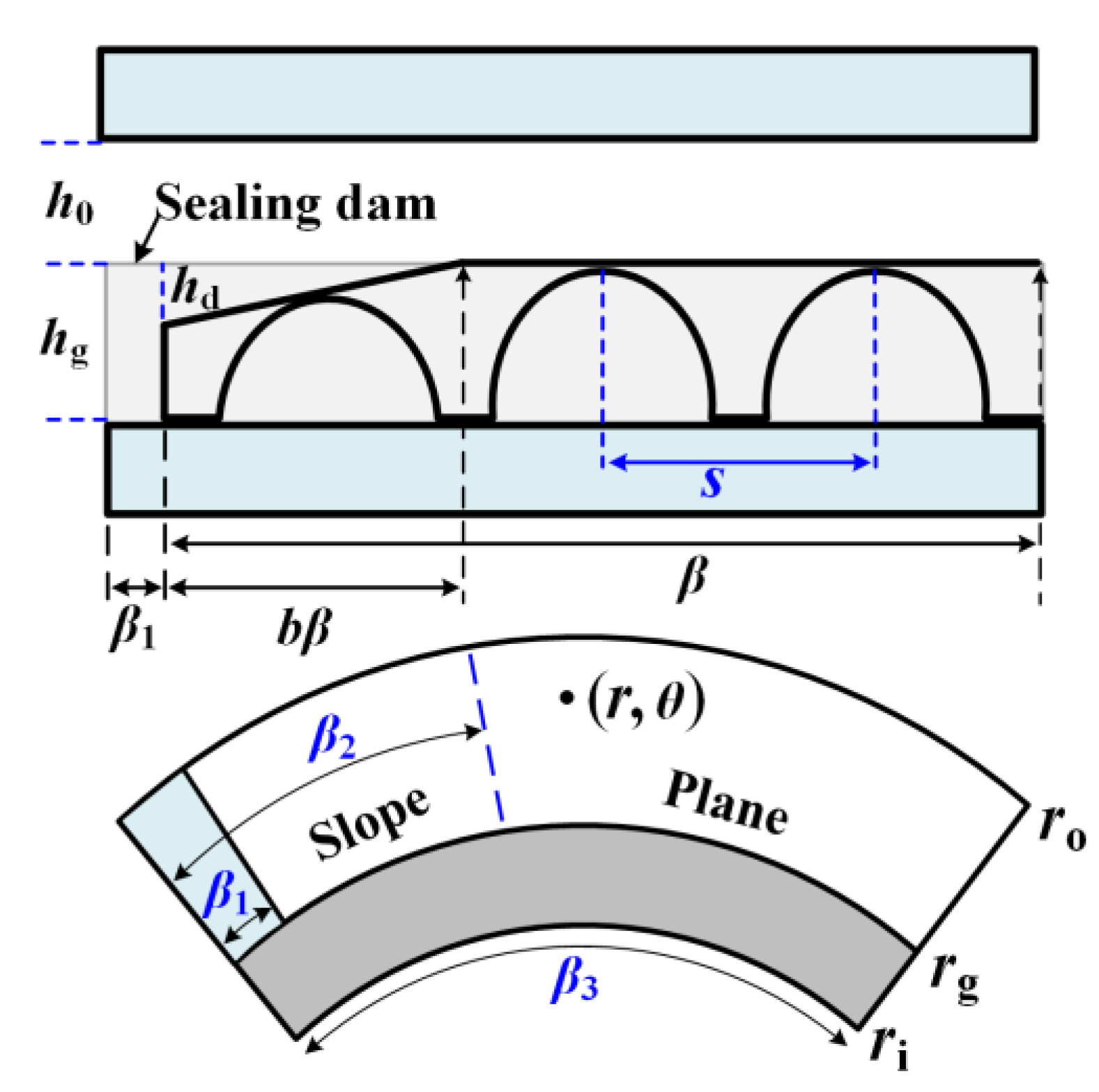
2.3. Control Equation of Film Thickness

2.3.1. Establishment of Film Thickness Equation

The elastic supporting structure of CFFGS is composed of multiple fan-shaped foils with the same structure and shape arranged sequentially. Under the condition that the rotor and stator are not tilted, the film thickness of each foil surface is the same [17]. As shown in Figure 2, the plane section of the top foil is always flush with the sealing dam before the foil is deformed. Neglecting the rigid surface deformation of the rotor and stator, according to the structure and deformation characteristics of the foil, the film thickness equation of lubricating gas film is established [17].
According to the geometry and film thickness distribution in Figure 2, the dimensionless steady-state film thickness equation of CFFGS can be expressed as:
H = H 0 + G ( r , θ ) + U ( r , θ )
The dimensionless definition of each variable in Equation (6) is as follows:
H 0 = h 0 h d ; U = u ( r , θ ) h d ; G ( r , θ ) = g ( r , θ ) h d
In Equation (7), g(r,θ) represents the height difference between the foil surface and the sealing dam, and u(r,θ) represents the circumferential deformation of the foil, as follows:
g ( r , θ ) = { h g r g r r o , 0 θ < β 1 h d ( 1 θ β 1 b β ) r g r r o , β 1 θ < β 2 0 r g r r o , β 2 θ β 3 0 r i r < r g u ( r , θ ) = { 0 r g r r o , 0 θ < β 1 ( p p o ) s k b r g r r o , β 1 θ β 3 0 r i r < r g
In the above equations, b is the slope ratio, which is defined as the proportion of the slope section to the single fan-shaped foil.

2.3.2. Mechanical Model of Foil Deformation

As shown in Figure 3, the elastic bump foil is equated to a linear stiffness spring model. That is, the bump foil is regarded as a linear spring with a certain axial deformation stiffness. Neglecting the stiffness of the top foil, and neglecting the coulomb friction between the top foil and the bump foil, and between the bump foil and the sealing ring. Currently, the deformation of the foil is linear to the surface force of the foil. Then, the relationship between the deformation of the bump foil and the film pressure is shown in Equation (9) [35]. The film pressure p will change with the change in working conditions, resulting in foil deformation u changes.
( p p o ) = k b s u
The dimensionless form is:
P P o = K b U
where:
P o = p o p a ; K b = k b h d p a s ; U = u h d
The compliance coefficient α characterizes the axial deformation ability of the foil, which is defined as the reciprocal of the dimensionless stiffness [31], and is expressed as:
α = 1 K b = p a s k b h d

2.4. Pressure Boundary Conditions

Periodic pressure boundary conditions:
P ( r , θ ) = P ( r , θ + 2 π / N )
To improve the calculation efficiency, 1/N of the sealing face is selected as the calculation field. The inlet of the sealing dam and boundary of the foil adopt the mandatory pressure boundary condition of Equation (14).
P = { p o p a R = R o = r o r i p o p a R = R g = r g r i p o p a R g < R < R o , θ = β 1 p o p a R g < R < R o , θ = β 3
Due to the large pressure difference between the inner radius and outer radius of the sealing dam, the radial velocity of the gas flow under the action of the pressure difference is higher. However, when the gas flow is choked by exceeding the speed of sound, the outlet pressure at the inner radius of the sealing dam is no longer equal to the environmental pressure. The mandatory outlet pressure boundary is currently no longer applicable. Therefore, different outlet pressure boundary conditions should be adopted at the inner radius of the sealing dam when neglecting and considering the choked flow.
Neglecting the outlet choked flow of the sealing dam, the outlet pressure of the sealing dam adopts a mandatory outlet pressure boundary condition:
P ( R = R i = 1 ) = p i p a
Considering the outlet choked flow of the sealing dam, the outlet pressure of the sealing dam adopts a choked outlet pressure boundary condition. Neglecting the influence of the circumferential velocity of the gas flow [25,36], and the choked flow can be judged using the outlet Mach number Maexit (Maexit = vr/c, where vr is the radial velocity of the gas flow and c is the speed of sound). Specifically, if the outlet gas flow is choked (Maexit > 1), the outlet pressure needs to be corrected until the outlet radial velocity drops to the sound velocity. If the outlet radial flow velocity is less than or equal to the speed of sound, there is no or just-right choking (Maexit ≤ 1) at this time. The outlet pressure is equal to the environmental pressure and does not need to be corrected at this time. The choked outlet pressure boundary condition is set as follows:
P ( R = R i = 1 ) = { p i p a M a e x i t 1 p i p a + Δ p i p a M a exit > 1
where Δpi is the outlet pressure correction amount.

2.5. Calculation of Sealing Performance Parameters

In this paper, the steady-state Reynolds equations are solved using the finite difference method, and the computational flow is shown in Figure 4. In the figure, m1 and m2 are the number of circumferential and radial grids, respectively, i and j denote the positions of the circumferential and radial grid points, respectively, d is the number of solution iterations, and the convergence residual err = 10−6. When the outlet choking pressure needs to be corrected, the pressure correction Δpi is continuously adjusted by the dichotomy method until the choking criterion (Maexit = 1) is satisfied. Finally, the sealing performance parameters are calculated according to the final film pressure and film thickness as follows.
Opening force characterizes the bearing capacity of the CFFGS, and the expression is:
F o = 0 2 π r i r g p r d r d θ + 0 2 π r g r o ( p p o ) r d r d θ
According to the principle of flow conservation, the leakage rate does not change with radius [37]. The medium leakage of CFFGS occurs on the surface of the sealing dam. Under the condition that the gas viscosity and the width of the sealing dam are unchanged, the leakage rate is determined by the pressure difference between the inner and outer radius of the sealing dam and the balance film thickness. The inertia effect will change the radial flow velocity of the gas, which, in turn, affects the leakage rate. Therefore, this paper needs to study the inertia effect on the volume leakage rate. The volume leakage rate when neglecting and considering inertia is shown in Equations (18) and (19) [38,39].
Q = 0 2 π r h 3 12 μ p p i p r d θ
Q = 0 2 π Ω 2 r 2 h 3 p 40 μ R g T p p i r h 3 12 μ p p i p r d θ

3. Results and Discussion

The basic calculation parameters are given in Table 1. The selection of sealing structural parameters in Table 1 refers to the classic literature of dry gas seal and foil bearing. The basic operating parameters are set according to normal temperature, high speed, and high pressure. In the calculations, all parameters are set according to Table 1 except for the studied variable parameters and special description parameters.

3.1. Correctness Verification of Calculation Program

In this paper, MATLAB calculation software is used to solve the gas–elastic coupling lubrication model of CFFGS with the finite difference method. This section focuses on verifying the accuracy of the lubrication theory model and numerical calculation method.
The calculation results of this paper are compared with the literature values to verify the correctness of the calculation program considering choked flow and inertia effect. Figure 5a is the literature value [38] and the calculated value of the outlet pressure of the dry gas seal under the condition of considering choked flow. Figure 5b is the literature value [26] and the calculated value of the radial pressure distribution of the mechanical gas face seal under the condition of considering choked flow. Figure 6 is the literature value [39] and the calculated value of the opening force of the dry gas seal under the condition of considering the inertia effect, where ΔFo represents the difference in opening force between neglecting and considering inertia effect.
It can be seen from Figure 5a that under the condition of considering choked flow, the literature value of outlet pressure under different medium pressures is in good agreement with the calculated value, and the average relative error is 3.2%. The choked flows both occur at the pressure of 2.75 MPa. In addition, as is shown in Figure 5b, under the condition of considering choked flow, the literature values of film pressure at different radial positions are close to the calculated values and the average relative error is 4.8%. All the above average relative errors are within 5%, which verifies the correctness and accuracy of the calculation program considering choked flow.
It can be seen from Figure 6 that under the condition of considering the inertia effect, the average relative error of the opening force calculated in this paper and that in the literature is 0.8%. The average relative error of ΔFo is 0.19%, which verifies the correctness of the calculation program of the inertia correction lubrication model.

3.2. Influence of Choked Flow on Sealing Characteristics

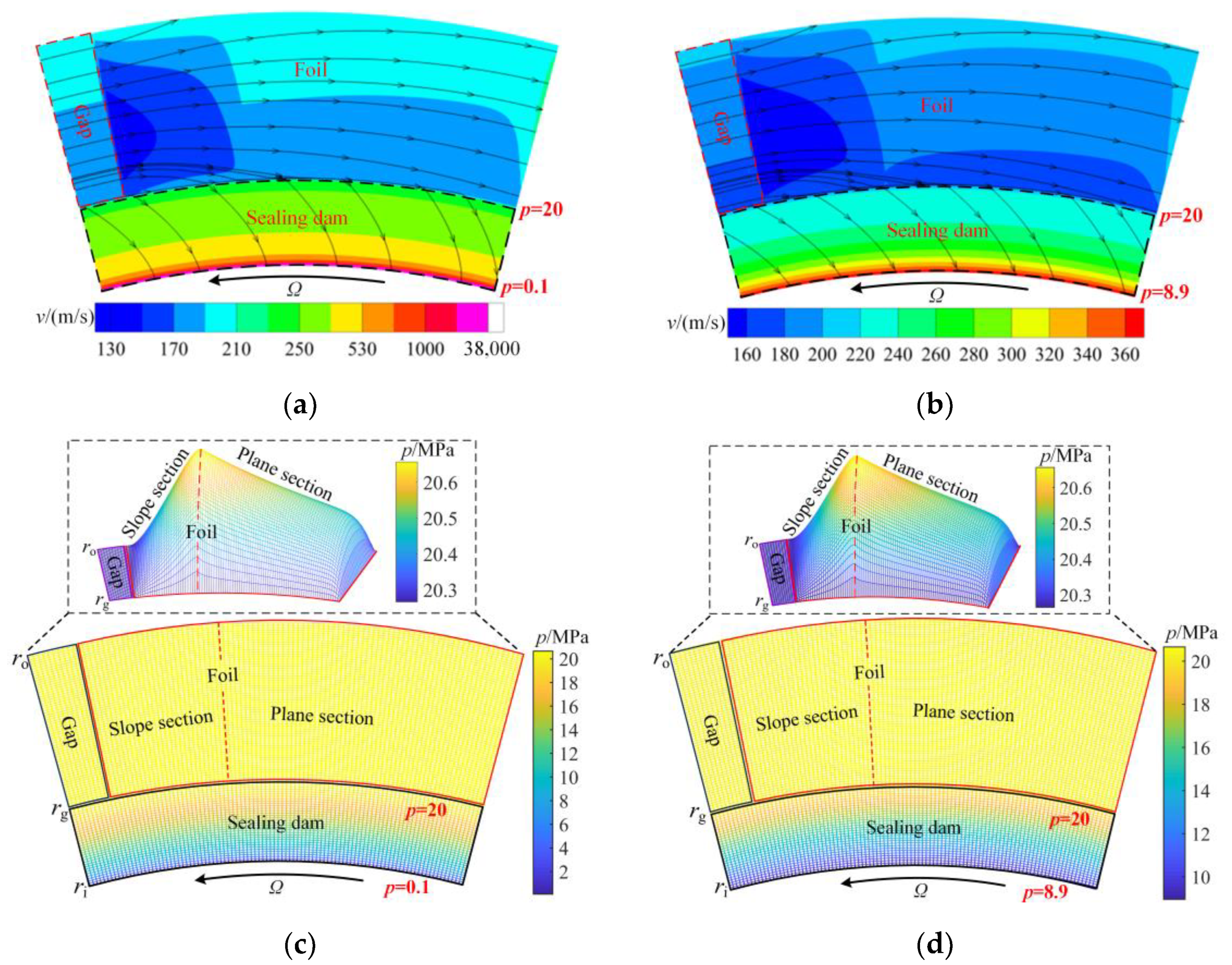
3.2.1. Influence of Choked Flow on Flow Field of Dynamic Lubrication

Figure 7 shows the spatial distribution of fluid velocity and film pressure when neglecting and considering choked flow. It can be seen from Figure 7a,b that the shear flow is prominent under the high-speed operation of the seal, and the radial differential pressure flow in the foil area is weak, which causes the gas flow in the foil area to be mainly circumferential. Additionally, the gas in the middle of the foil tends to diffuse to the inside and outside under the extrusion of the high-pressure medium. However, the gas on the surface of the sealing dam is mainly in radial flow. The reasons are as follows. The outer radius of the sealing dam is the high-pressure medium, the inner radius is the atmospheric environment, and the effect of the radial differential pressure flow is much greater than the circumferential shear flow, resulting in radial leakage flow of the medium on the surface of the sealing dam. In addition, the flow velocity continues to increase when the high-pressure medium flows along the sealing dam to the atmospheric side of the inner radius. It is worth noting that when neglecting the choked flow, the flow velocity at the outlet of the sealing dam is much higher than the flow velocity considering the choked flow. This is because when the choked flow is neglected, the flow velocity in the radial convergent micro gap is not limited. When the choked flow is considered and the maximum flow velocity in the convergent micro gap reaches the local speed of sound, this results in the choked flow at the outlet and the flow velocity reaches its maximum at this time.
According to the above analysis, the choked flow in Figure 7a,b occurs only on the surface of sealing dam, thus, the choked flow has no effect on the flow velocity and film pressure in the gap and foil areas. As shown in Figure 7c,d, when the gas flows through the convergent gap formed by the inclined foil, the film pressure continues to increase due to the generation of the hydrodynamic effect, and the film pressure reaches the maximum at the junction of the slope section and the plane section. Moreover, the gas flow in the plane section is affected by the end leakage, which causes the film pressure to decrease gradually. However, film pressure distribution on the surface of the sealing dam in Figure 7c,d is different. Specifically, the outlet pressure of the sealing dam is equal to the atmospheric environmental pressure of 0.1 MPa when the choked flow is neglected, and the outlet pressure of the sealing dam reaches 8.9 MPa when considering the choked flow. Combined with Figure 7a,b to analyze the above phenomenon, when neglecting the choked flow, the high-pressure medium flows along the surface of the sealing dam towards the inner radius of the atmospheric side and connects with the atmospheric environment at the inner radius of the sealing dam. Therefore, the outlet pressure of the sealing dam is the same as the ambient pressure. However, when considering the choked flow, if the flow velocity of the high-pressure medium is greater than or equal to the local speed of sound, the choked flow will contribute to the increase in film pressure. Accordingly, the outlet pressure of the sealing dam is much higher than the ambient pressure. In summary, under high-pressure conditions, the choked flow has a great influence on the outlet flow velocity and outlet pressure of the sealing dam, and it is crucial to consider the choked flow to improve the accuracy of flow field calculation.
To explore the correlation between operating parameters and choked flow, the effects of medium pressure, rotational speed, and balance film thickness on the choked outlet pressure are studied, respectively. Figure 8a shows the variation in choked outlet pressure under different medium pressure and balance film thickness. It can be seen from Figure 8a that when the balance film thickness is unchanged, the outlet pressure increases with the increase in medium pressure, indicating that the choked flow is more and more obvious. This is because the increase in medium pressure will significantly enhance the radial pressure differential flow. When the flow velocity reaches the local speed of sound, the flow velocity cannot be increased, but the flow trend continues to increase at this time, resulting in more serious choked flow, and then raising the outlet pressure. In addition, when the medium pressure is unchanged, the larger the balance film thickness, the higher the outlet pressure, indicating more obvious choked flow. This is because the increase in the balance film thickness will reduce the obstruction of gas flow, which leads to the increase in radial flow velocity. When the flow velocity reaches the critical speed of choked flow, the increase in balance film thickness will aggravate the choked flow, which brings higher film pressure. Therefore, when the flow velocity reaches the critical speed of choked flow, increasing the balance film thickness or increasing the medium pressure will lead to the aggravation of the choking effect and the increase in the outlet pressure.
The balance film thickness of CFFGS during stable operation is generally maintained at 3~8 μm. In Figure 8a, when the medium pressure is higher than 2 MPa, the choked flow will have a certain impact on the flow field. The outlet pressure is no longer the same as the atmospheric environment, and it is necessary to consider the choked flow to modify the outlet pressure currently. Figure 8b shows the influence of rotational speed and balance film thickness on the outlet pressure pi. It is worth noting that the outlet pressure is independent of the rotational speed. This is because the radial flow velocity is the direct factor affecting the choked flow on the surface of the sealing dam. However, when the rotational speed increases or decreases, there is no hydrodynamic effect on the face of the horizontal and smooth sealing dam, the pressure field of the sealing dam does not change accordingly, and there is no change in the radial flow velocity caused by the varied pressure field. Therefore, in the case of a certain medium pressure and balance film thickness, changing the rotational speed alone does not affect the radial flow velocity and the sealing outlet pressure remains unchanged. Thus, the influence of rotational speed on the choked flow will not be studied below.

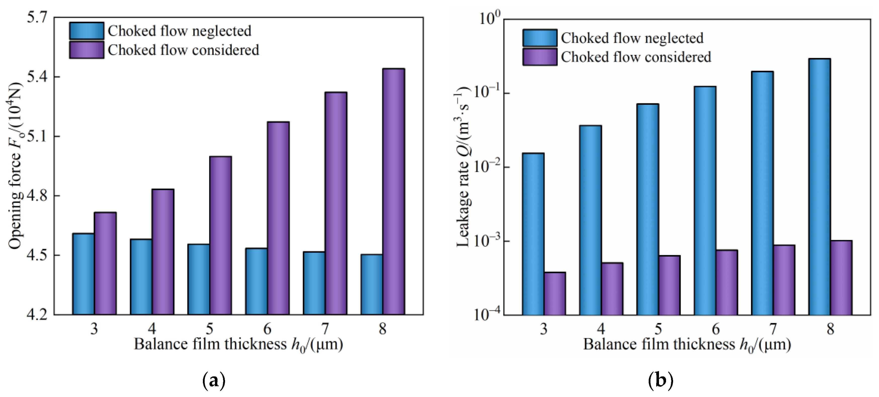
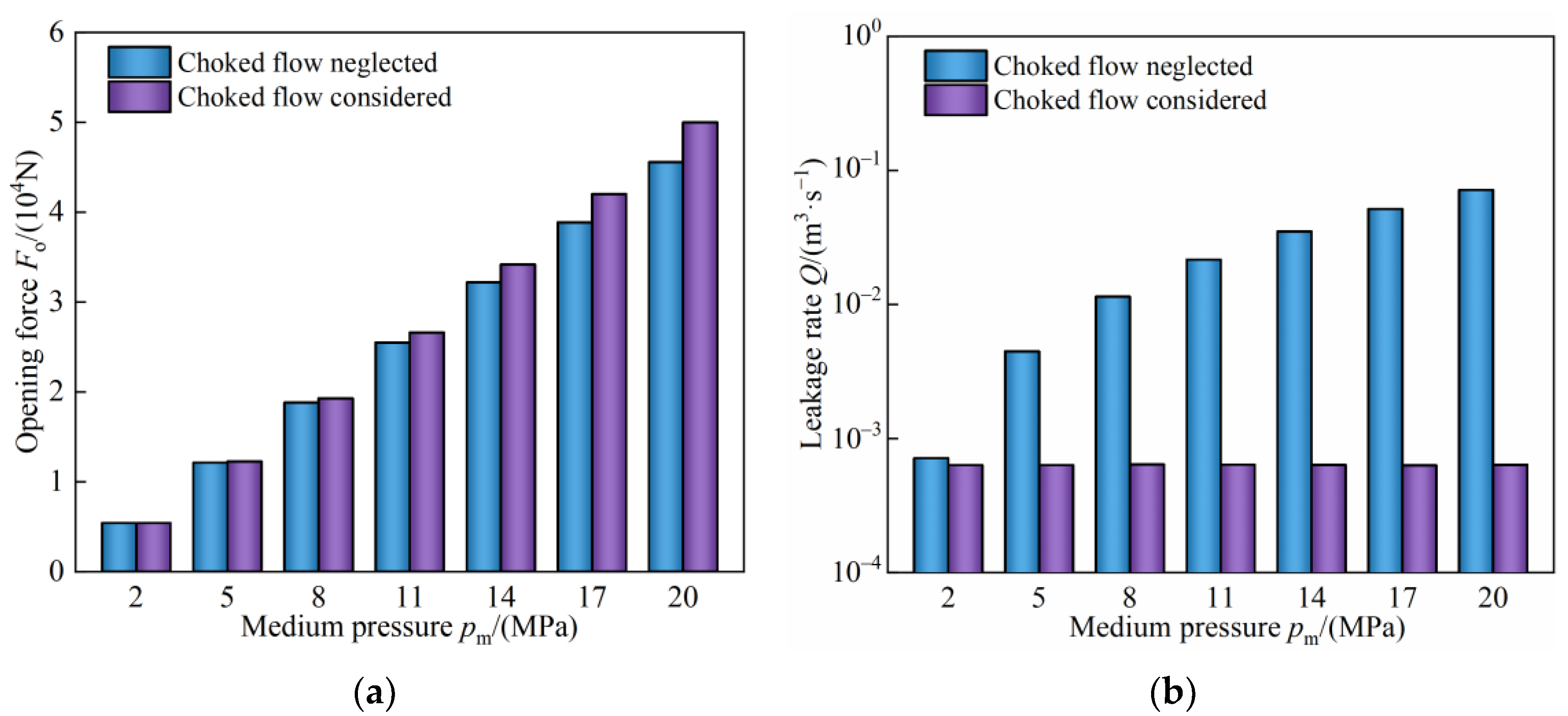
3.2.2. Influence of Choked Flow on Sealing Performance

From the analysis of Section 3.2.1, choked flow has a significant impact on the flow field of CFFGS. Meanwhile, the change in the flow field will further affect the sealing performance. Therefore, in order to explore the influence of choked flow on sealing performance, the variation in sealing performance with balance film thickness and medium pressure when neglecting and considering choked flow is compared.
Figure 9 shows the influence of choked flow on sealing performance under different balance film thicknesses. As can be seen from Figure 9a, with the increase in balance film thickness, the opening force gradually decreases when neglecting the choked flow. This is because the increase in balance film thickness will weaken the hydrodynamic and hydrostatic effect of the lubricating gas, resulting in reduced film pressure and opening force. However, the opening force increases with the increase in balance film thickness when considering the choked flow. The reasons are as follows, although the increase in balance film thickness will weaken the hydrodynamic and hydrostatic effect and reduce the film pressure of the foil surface. However, when the choking effect occurs, the increase in the balance film thickness will aggravate the choked flow on the surface of the sealing dam and then increase the film pressure. Moreover, the opening performance improvement brought by the increase in the film pressure of the sealing dam area is enough to make up for the decrease in the opening performance caused by the decreased film pressure of the foil area. Hence, the opening force is ultimately improved.
In Figure 9b, the leakage rate increases with the increased balance film thickness when neglecting and considering choked flow, because the increase in balance film thickness leads to an increase in flow velocity and volume flow of the sealing medium. The difference lies in the leakage rate, which is much higher with choked flow neglected than that with choked flow considered. Analysis of the above phenomena from the perspective of flow field is as follows. When considering the choked flow, the maximum flow velocity on the surface of the sealing dam is unable to exceed the local speed of sound. However, the sealing outlet pressure with choked flow neglected is always the atmospheric environment pressure, hence the strong pressure differential flow causes the flow velocity on the surface of the sealing dam to be much higher than the local speed of sound. Consequently, the leakage volume per unit of time when neglecting choked flow is much higher than that when considering choked flow. In summary, when the gas flow on the sealing face is choked due to the change in the balance film thickness, neglecting the choked flow will deviate the sealing performance from the actual calculation value, which is a smaller opening force and larger leakage rate.
Figure 10 shows the influence of choked flow on sealing performance under different medium pressures. The higher the medium pressure, the stronger the hydrostatic effect of the end gas, thus, the opening force in Figure 10a increases with the increased medium pressure. However, the opening force with choked flow considered is higher than that with choked flow neglected, and the higher the medium pressure, the more obvious the difference. The reason is that when considering the choked flow, the pressure field is not only affected by the medium pressure, but also affected by the choked flow caused by the change in medium pressure, and the higher the medium pressure, the greater the impact of the choked flow. Therefore, the film pressure of the sealing dam with choked flow considered is higher than that with choked flow neglected, and the opening performance is outstanding. As shown in Figure 10b, when neglecting the choked flow, the leakage rate increases with the increased medium pressure, but the leakage rate considering the choked flow is essentially not affected by the medium pressure. The above phenomenon is explained as follows. When the choked flow is neglected, the increase in medium pressure will strengthen the pressure difference flow on the surface of the sealing dam. Additionally, the radial flow velocity increases at this time, increasing the leakage rate. In contrast, when the choked flow is considered, the maximum gas flow velocity on the surface of the sealing dam is unable to exceed the local speed of sound. Hence, the flow velocity of the sealing outlet under different medium pressures is essentially the same, and, accordingly, the leakage rate is essentially unchanged. In summary, under high medium pressure, the choked flow has an important impact on the opening force and leakage rate of CFFGS, and, especially in the calculation of leakage rate, choked flow should not be neglected.

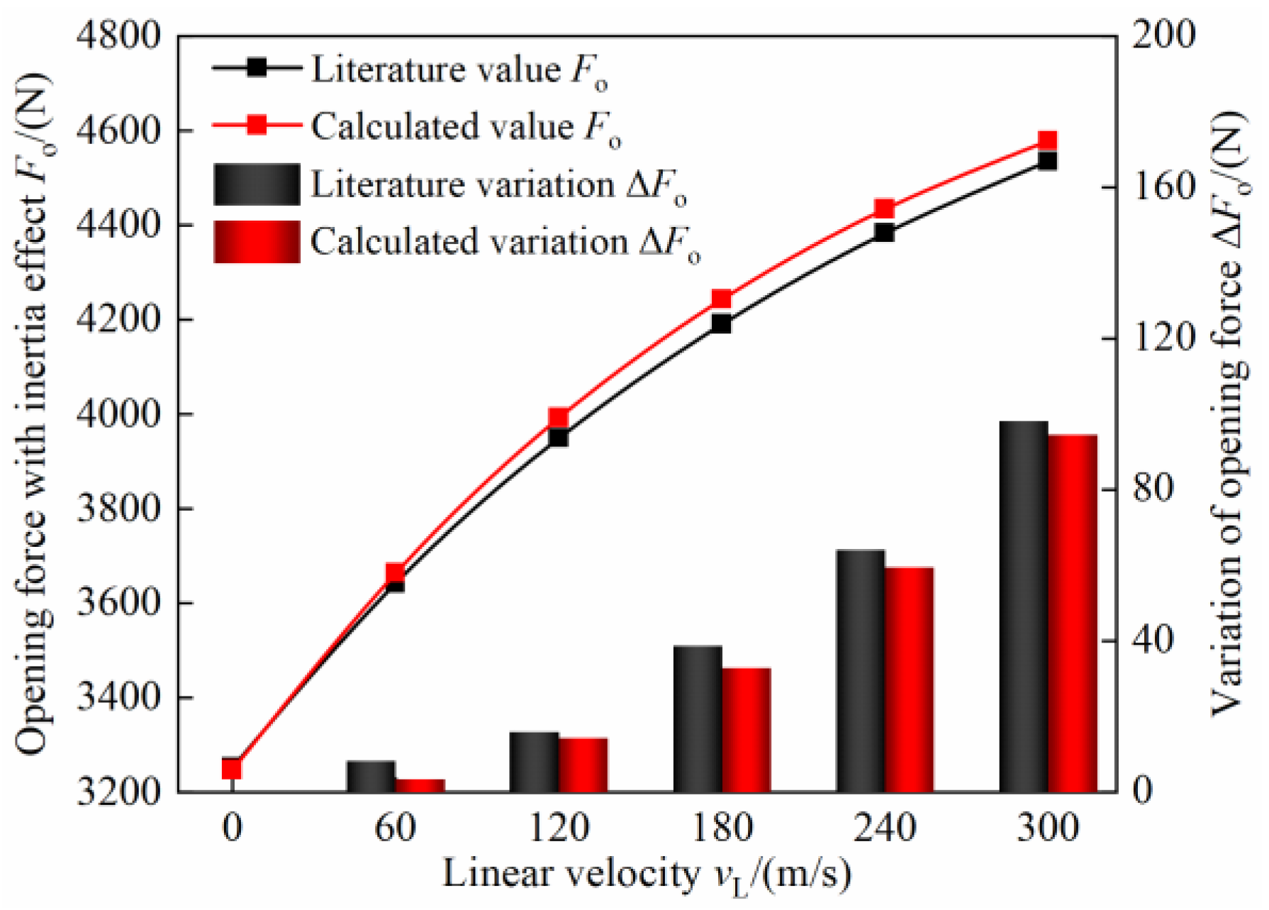
3.3. Influence of Inertia Effect on Sealing Characteristics

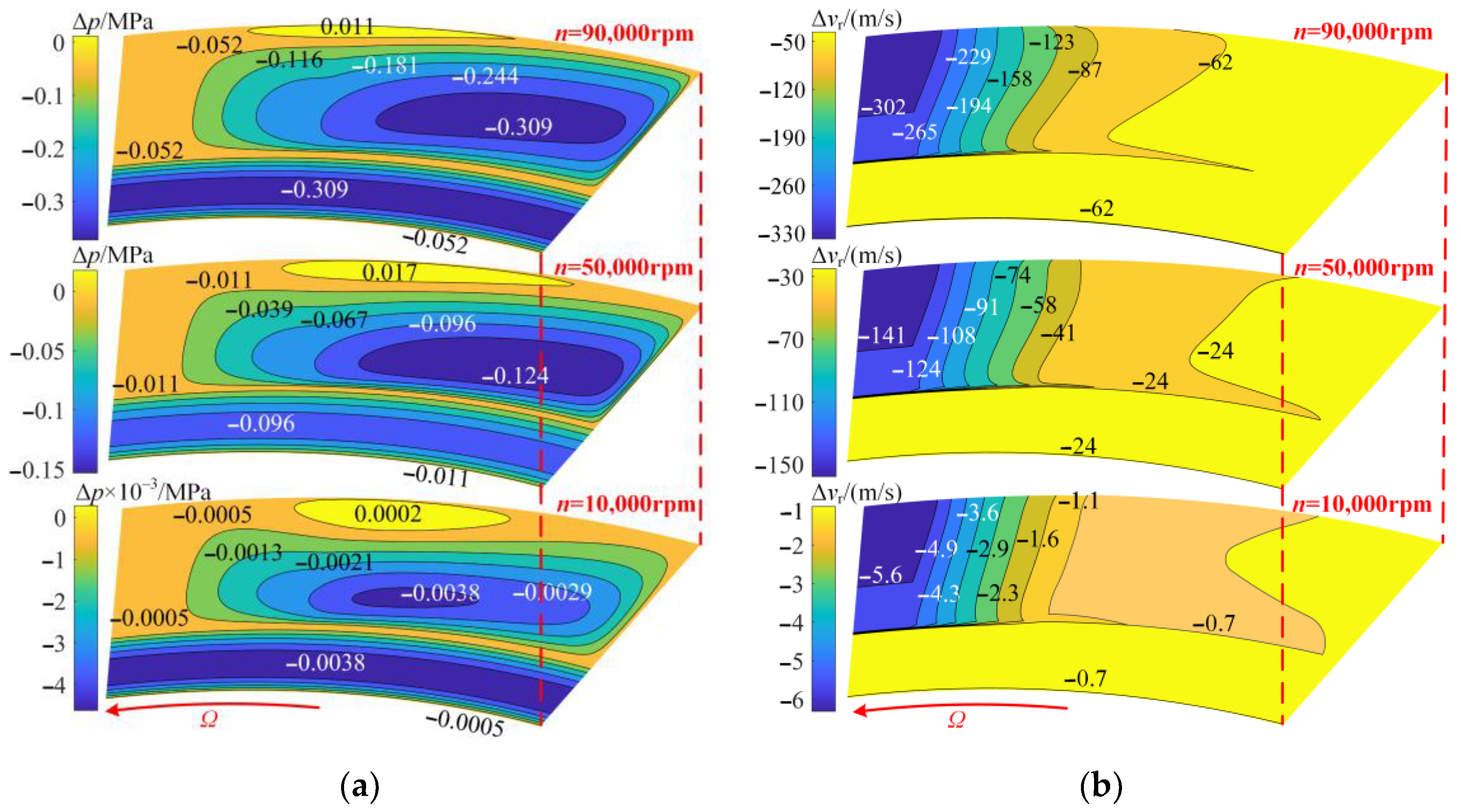
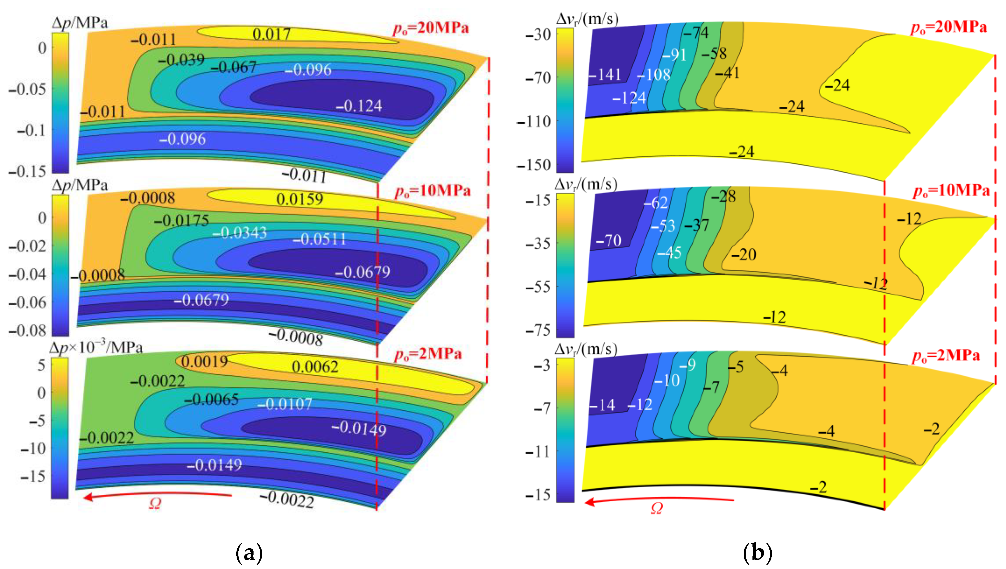
3.3.1. Influence of Inertia Effect on Flow Field of Dynamic Lubrication

The results in Section 3.2 show that the choked flow has a significant impact on the flow field and sealing performance of CFFGS. Therefore, to ensure that the calculation and analysis of gas inertia effect are more realistic, the following studies with inertia effect considered are based on the outlet pressure boundary modified by considering choked flow.
Figure 11 shows the flow velocity field when neglecting and considering inertia effect. It can be seen from Figure 11a,b that the gas flow in the foil area is dominated by circumferential flow, and the difference is that the above gas flow in Figure 11a tends to spread to the inner and outer sides under the extrusion of high-pressure gas film, while the above gas flow in Figure 11b flows to the outer radial side. The reasons are as follows. On the one hand, the lubricating medium in Figure 11b is subjected to inertia force to produce centrifugal motion, resulting in the radial flow direction on the inner side of the foil area changing from inward to outward. On the other hand, under the action of inertia force in Figure 11b, the tendency of the lubricating medium on the outer side of the foil area to flow to the outside is further strengthened. Thus, the superposition of the above phenomena leads to the gas flow of the foil area in Figure 11b flowing to the outer radius side of the seal. However, under the action of a strong pressure difference between the inner and outer radius, the gas on the surface of the sealing dam has a more pronounced radial flow than in the foil area. In addition, it can be found that the flow velocity of the sealing dam considering inertia effect is significantly lower than that without the inertia effect, which is also because inertia force weakens the tendency of gas to flow radially.
In summary, the pressure differential flow in the foil area is weaker, and the inertia effect will have a significant impact on both the velocity and direction of the gas flow. Additionally, the pressure difference flow on the surface of the sealing dam is forceful, and although the inertia force cannot change the direction of the gas flow, it will cause the radial flow velocity of the gas to change. Consequently, the influence of the high-speed gas inertia effect on the flow field of CFFGS needs to be further analyzed.
The pressure difference Δp is defined as the pressure considering the inertia effect minus the pressure neglecting inertia effect, and the radial flow velocity difference Δvr is the radial flow velocity considering the inertia effect minus the radial flow velocity neglecting inertia effect. The influence of inertia effect on the flow field is analyzed using the above pressure difference and radial flow velocity difference, where the direction of the radial flow velocity is from the outer radius to the inner radius.
Figure 12 shows the influence of the inertia effect on the pressure field and velocity field at different rotational speeds. It can be seen from Figure 12b that the inertia effect will reduce the radial flow velocity (Δvr < 0) at different rotational speeds, and the higher the rotational speed, the greater the decrease. It can be seen from Figure 11 that this is caused by the centrifugal movement of the gas under the action of inertia force. In Figure 12a, the film pressure of the sealing dam decreases after considering the inertia effect (Δp < 0). This is because the radial velocity of the gas flow on the surface of the sealing dam decreases under the action of inertia force, resulting in the weakening of the hydrodynamic effect of the gas of the sealing dam. Compared with neglecting the inertia effect, the film pressure of the inner radius of the foil decreases when considering the inertia effect, and the film pressure of the outer radius increases (Δp > 0). The reasons are shown in Figure 11; compared with the flow field neglecting the inertia effect, the gas inside and in the middle of the foil after considering the inertia effect is significantly shifted to the outer radius, resulting in a decrease in the film pressure of the above area. Meanwhile, the inner and middle high-pressure gases accumulate on the outer radius, which increases the film pressure of the outer radius. In addition, the inertia force of the gas increases with the increase in the rotational speed, which directly leads to the enlargement of the pressure difference between neglecting and considering inertia. It is worth noting that the pressure drop area of the foil section increases with the increasing rotational speed, and the pressure rise area decreases. The reasons are as follows. The higher the rotational speed, the stronger the tendency of gas in the foil section to flow outward under the action of inertia force, and the wider the pressure drop area affected on the inside. At high rotational speed, the inertia effect is obvious, which leads to it being hard for the gas flow to accumulate on the outer radius, and it finally flows out of the sealing surface, resulting in a decrease in the pressure rise area.
As shown in Figure 13, the influence trend of inertia force on the pressure field and velocity field under different medium pressure is essentially the same as that of Figure 12. To be specific, compared with neglecting the inertia effect, considering the inertia effect will reduce the radial flow velocity of the gas, reduce the film pressure inside the sealing face, and increase the film pressure outside the sealing face. In addition, the higher the medium pressure, the greater the influence of inertia force on the film pressure difference Δp and radial flow velocity difference Δvr. This is because the inertia force is mainly affected by circumferential motion speed and the mass of the lubricating gas. The gas circumferential pressure differential flow is prominent and the unit volume mass is larger at high pressure, resulting in a stronger inertia effect. Furthermore, as the medium pressure increases from 2 MPa to 20 MPa, the area of the Δp < 0 continues to increase, and the area of the Δp > 0 decreases, which indicates that the increase in medium pressure will enhance the inertia effect and have a significant impact on the flow field distribution as well.
In summary, the rotational speed and medium pressure are the pivotal factors affecting the gas inertia effect, which, in turn, has a significant impact on the pressure field and velocity field of the CFFGS. Consequently, the inertia effect should be considered in the calculation and analysis under high speed and high medium pressure.

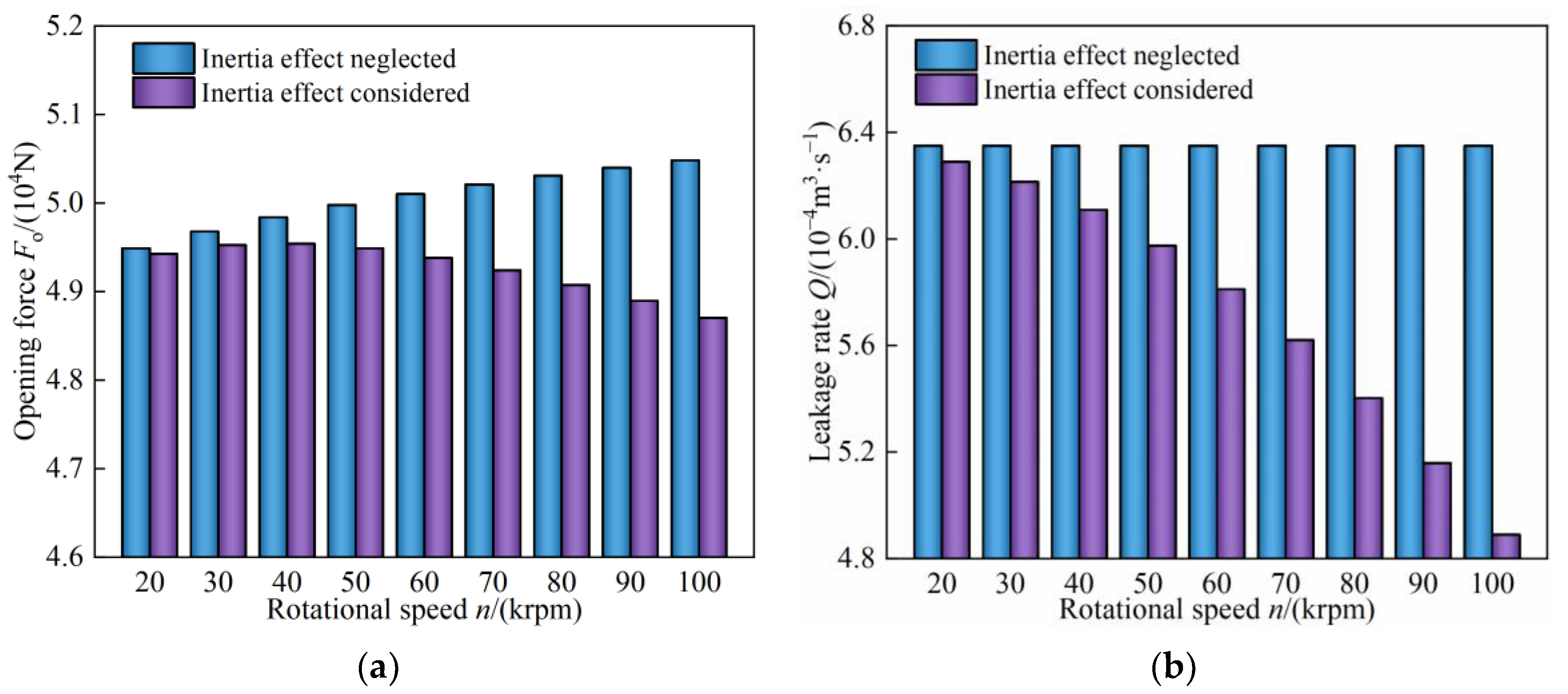
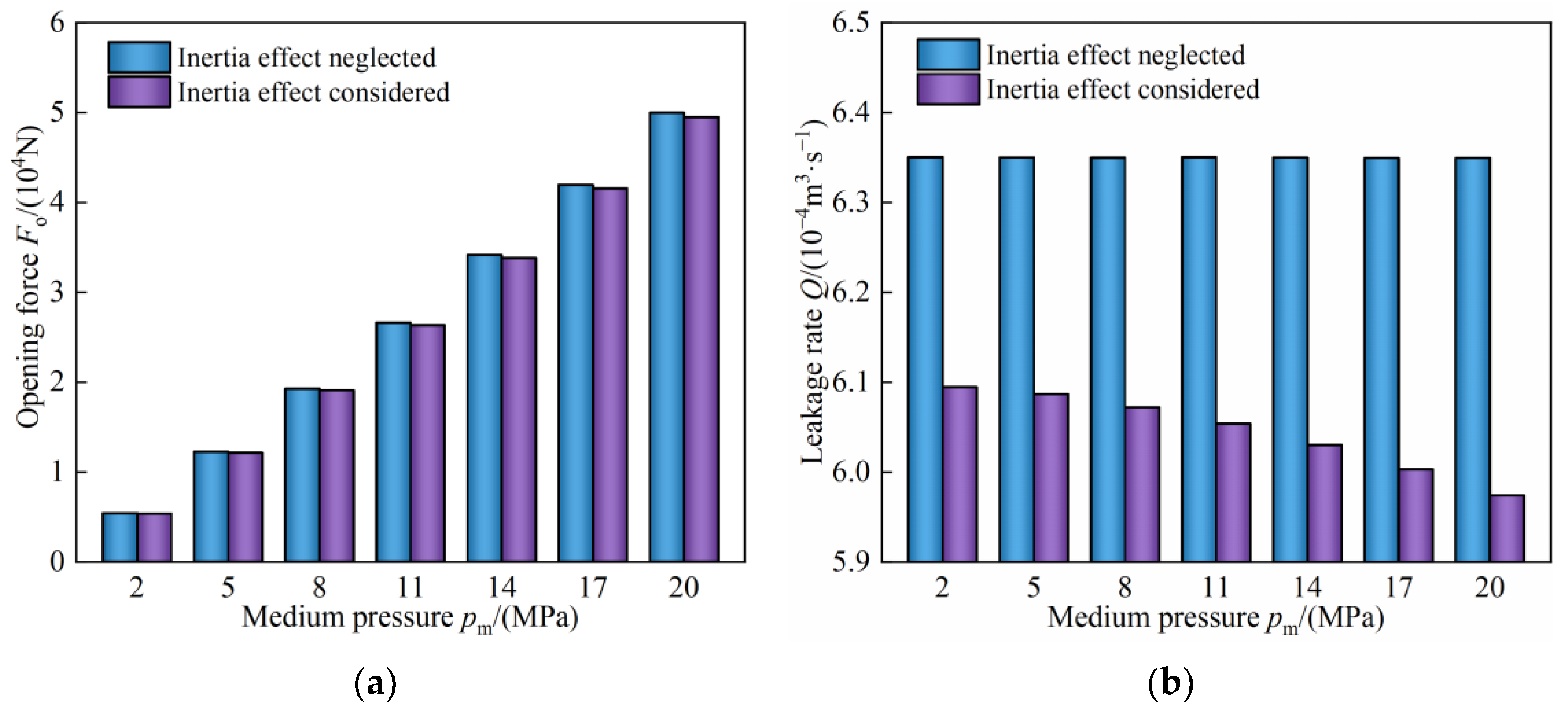
3.3.2. Influence of Inertia Effect on Sealing Performance

From the analysis of Section 3.3.1, the inertia effect has a significant effect on the flow field distribution of the CFFGS, which will further affect the sealing performance. To explore the influence of the inertia effect on sealing performance, the change law of sealing performance with rotational speed and medium pressure when neglecting and considering inertia is compared.
The influence of the inertia effect on sealing performance under different rotational speeds is shown in Figure 14. It can be seen from Figure 14a that when inertia effect is neglected, the hydrodynamic effect of the lubricating gas increases continuously with the increase in rotational speed from 20 krpm to 100 krpm, and the opening force increases accordingly. However, the opening force considering the inertia effect first increases and then decreases gradually. It can be seen from Section 3.3.1 that the inertia force at different rotational speeds will cause the pressure drop, thereby weakening the opening performance. When the rotational speed is less than 40 krpm, the inertia effect is weak, and the hydrodynamic effect caused by the increasing rotational speed is enough to make up for the loss of opening performance caused by the enhancing inertia effect. Opening force is, therefore, improved to a certain extent. However, when the rotational speed is greater than 40 krpm, the impact of the inertia effect is highlighted, and the gas flow is more affected by the inertia effect than the hydrodynamic effect. As a result, the opening force of the end face is continuously reduced. In Figure 14b, the leakage rate neglecting the inertia effect remains unchanged at different speeds. Because there is no hydrodynamic effect on the horizontal and smooth surface of the sealing dam, the change in rotational speed does not affect the pressure field of the sealing dam. Thus, the pressure difference between the inner and outer radius of the sealing dam is unchanged, which leads to the radial flow velocity and leakage rate being unchanged. The leakage rate considering the inertia effect continues to decrease with the increase in rotational speed and is lower than that neglecting the inertia effect. The reasons for this can be seen in Figure 12b. The radial flow velocity considering the inertia effect is smaller than that of neglecting the inertia effect, which explains the lower leakage rate. In addition, the inertia effect increases with the increasing rotational speed, resulting in a continuous decrease in the radial flow velocity of the gas on the surface of the sealing dam, and the leakage rate decreases accordingly.
The inertia effect on sealing performance under different medium pressures is shown in Figure 15. It can be seen from Figure 15a that as the medium pressure increases from 2 MPa to 20 MPa, the hydrostatic pressure effect is enhanced, and the opening force increases accordingly. The opening force considering inertia effect at different speeds is slightly lower than that neglecting the inertia effect. The reason can be seen in Figure 13a. Under different rotational speeds, the film pressure considering the inertia effect is lower than that neglecting the inertia effect, hence the hydrostatic effect is weaker and the opening performance is worse. Moreover, on the one hand, the leakage rate neglecting the inertia effect in Figure 15b does not vary with the changing medium pressure. This is because the maximum flow velocity of the choked flow on the surface of the sealing dam is extremely close to the local sound velocity, so the leakage rate essentially remains unchanged. On the other hand, the leakage rate considering the inertia effect is obviously lower than that neglecting the inertia effect, and the difference increases with the increasing medium pressure. Figure 13b explains that this is because the radial flow velocity considering the inertia effect is lower than that neglecting the inertia effect, and the larger the medium pressure, the greater the difference between the two.
In summary, changes in rotational speed and medium pressure will have an obvious impact on the inertia force, which, in turn, leads to changes in sealing opening performance and leakage control performance. Meanwhile, the larger the rotational speed, the higher the medium pressure and the greater the change amplitude of the above performance. Consequently, under high rotational speed and high medium pressure, the influence of gas inertia effect on sealing performance should not be ignored.

4. Scientific Contribution

Few papers have studied the hypervelocity gas effects of foil seals. In this paper, a numerical solution model of gas–elastic coupling considering choked flow and inertia effect correction is established. It is necessary for us to analyze the effects of hypervelocity gas on sealing characteristics. In addition, the results of this study reveal the importance of the choked flow and inertia effect to compliant foil face gas seal. It is an essential supplement to the fundamental research on the gas effects of foil seals, and will provide theoretical guidance for the research, design, and performance prediction of high-parameter CFFGS.

5. Conclusions

a. Hypervelocity choked flow has a significant impact on the flow field and sealing performance of CFFGS, resulting in higher film pressure and lower flow velocity when the gas flow velocity on the surface of the sealing dam exceeds the sound velocity, especially obvious when the medium pressure is higher than 8 MPa. The increase in the medium pressure and balance film thickness are the key factors leading to the aggravation of the choked flow at the outlet of the sealing dam. In addition, the opening force is increased by up to 20% and the leakage rate is decreased by up to 99.6% when considering choked flow compared to ignoring choked flow.
b. The gas inertia effect causes obvious centrifugal movement of the gas flow, resulting in a 50% maximum decrease in the radial gas flow velocity and an increase in the overflowing trend. Eventually, the film pressure on the inside of the sealing face decreases, and the film pressure on the outside increases. Moreover, the inertia effect will lead to a maximum decrease of 3.5% in opening force and 23% in leakage rate, and this phenomenon is prominent under high rotational speed and high medium pressure, which means the rotational speed and medium pressure are the pivotal factors affecting the gas inertia effect.
c. Under ultra-high-speed (n > 50 krpm) and high-pressure (pm > 8 MPa) working conditions, the sealing outlet choked flow and the inertia effect are vital factors that cannot be ignored in the flow field analysis and seal performance prediction of CFFGS.

Author Contributions

Conceptualization, Y.C. and Q.W.; Methodology, Y.C. and Q.W.; Software, Q.W.; Validation, Q.W.; Formal Analysis, Y.C. and Q.W.; Investigation, Y.C. and Q.W.; Resources, Y.C.; Y.L. and X.L.; Data Curation, B.W. and J.J.; Writing—Original Draft Preparation, Y.C. and Q.W.; Writing—Review and Editing, Y.C. and Q.W.; Visualization, B.W. and J.J.; Supervision, Y.L. and X.L.; Project Administration, Y.C. and B.W.; Funding Acquisition, Y.C. and B.W. All authors have read and agreed to the published version of the manuscript.

Funding

This research was funded by the National Natural Science Foundation of China (51905513, 52005470), the Postdoctoral Science Foundation of Zhejiang Province, China (ZJ2020084), and the Fundamental Research Funds for the Provincial Universities of Zhejiang (2021YW77).

Data Availability Statement

Not applicable.

Conflicts of Interest

The authors declare no conflict of interest.

Nomenclature

bSlope ratio
FoOpening force
h, h0, hg, hdFilm thickness, balance film thickness, depth of gap section, wedge height
kb, KbUnit transverse stiffness, dimensionless axial deformation stiffness of bump foil
n, NRotational speed of shaft, number of foil
p, pa, pmFilm pressure, atmospheric pressure, pressure of high-pressure medium
pi, poPressure at inner radius, pressure at outer radius
PθDimensionless film pressure at the end of top foil
QSteady-state volume leakage rate
r, rg, ri, roRadius, outer radius of sealing dam, inner radius, and outer radius of seal face
RgGas constant
sLength of bump foil unit
TTemperature
uAxial deformation
v, vrFluid velocity and radial velocity of fluid
αCompliance coefficient
β, β1, β2, β3Angle of single foil and gap section, angle of slope section and plane section
θAngle
µGas viscosity
Λ1Compressibility number
Ω Angular velocity of shaft

References

  1. He, Q.; Huang, W.F.; Hu, G.Y.; Li, Y.J.; Liu, Y.; Wang, Y.M. Research status of the film-riding gas seal technologies in aeroengine. Aeroengine 2021, 4, 106–113. [Google Scholar]
  2. Chen, Y.; Jiang, J.B.; Peng, X.D.; Yan, T.H.; Li, Y.T.; Li, X.L.; Li, J.Y. Analysis of the interaction between the dynamic performance of the dry gas seal mechanical system and its influencing factors. Tribology 2019, 3, 269–278. [Google Scholar]
  3. Keller, D.; Jacobs, G.; Neumann, S. Development of a low-friction radial shaft seal: Using cfd simulations to optimise the microstructured sealing lip. Lubricants 2020, 8, 41. [Google Scholar] [CrossRef] [Green Version]
  4. Heshmat, H.; Ren, Z.; Hunsberger, A.; Walton, J.; Jahanmir, S. The emergence of compliant foil bearing and seal technologies in support of 21st century compressors and turbine engines. In Proceedings of the ASME 2010 International Mechanical Engineering Congress & Exposition, Vancouver, BC, Canada, 12–18 November 2010; pp. 95–103. [Google Scholar]
  5. Munson, J.H. Foil face seal testing. In Proceedings of the NASA Seal/Secondary Air System Workshop, Indianapolis, IN, USA, 1 November 2009; pp. 131–137. [Google Scholar]
  6. Li, C.; Du, J.; Li, J.; Xu, Z. Investigations on the frictional hysteresis effect of multi-leaf journal foil bearing: Modeling, predictions and validations. Lubricants 2022, 10, 261. [Google Scholar] [CrossRef]
  7. Liu, X.; Li, C.; Du, J. The fluid-structure-thermal performance analysis of gas foil thrust bearing by using computational fluid dynamics. Lubricants 2022, 10, 294. [Google Scholar] [CrossRef]
  8. Heshmat, H. Advanced development of air-lubricated foil thrust bearings. Lubr. Eng. 1984, 1, 21–26. [Google Scholar]
  9. Heshmat, H. Compliant Foil Seal. U.S. Patent 6,505,837, 14 January 2003. [Google Scholar]
  10. Agrawal, G.L.; Patel, K.H.; Munson, J.H. Hydrodynamic Foil Face Seal. U.S. Patent 7,261,300, 28 August 2007. [Google Scholar]
  11. Munson, J.H.; Grant, D.; Agrawal, G.L. Foil face seal development. In Proceedings of the 37th AIAA/ASME/SAE/ASEE Joint Propulsion Conference & Exhibit, Salt Lake City, UT, USA, 8–11 July 2001; p. 3483. [Google Scholar]
  12. Munson, J.H.; Grant, D.; Agrawal, G.L. Foil film riding face seal proof-of-concept testing. In Proceedings of the 38th AIAA/ASME/SAE/ASEE Joint Propulsion Conference & Exhibit, Indianapolis, IN, USA, 7–10 July 2002; p. 3791. [Google Scholar]
  13. Heshmat, H.; Walton, J. Innovative High-temperature compliant surface foil face seal development. In Proceedings of the 44th AIAA/ASME/SAE/ASEE Joint Propulsion Conference & Exhibit, Hartford, CT, USA, 21–23 July 2008; p. 4505. [Google Scholar]
  14. Bai, C.B.; Liu, M.H.; Sun, J.F.; Dai, D. Research on support structure performance of cylindrical gas film seal based on fluid-structure interaction. Lubr. Eng. 2020, 9, 64–70. [Google Scholar]
  15. Zhao, C.Y.; Liu, M.H.; Sun, J.F.; Wei, Q.F.; Xu, D.W. Research on mechanical properties of cylindrical gas film sealed bubbling supporting structure. Agric. Equip. Veh. Eng. 2021, 9, 32–37. [Google Scholar]
  16. Chen, Y.; Chen, K.; Peng, X.D.; Wang, B.; Li, X.; Jin, J. Research on the operation mechanism and performance of bump-type compliant foil face gas seal. J. Braz. Soc. Mech. Sci. Eng. 2022, 44, 325. [Google Scholar] [CrossRef]
  17. Chen, Y.; Wang, Q.G.; Peng, X.D.; Li, Y.; Wang, B.; Jin, J. Flow field and sealing performance analysis of compliant foil face gas seal. Adv. Mech. Eng. 2022, 6, 1–16. [Google Scholar] [CrossRef]
  18. Wang, Q.G.; Chen, Y.; Peng, X.D.; Li, Y.; Li, X.; Wang, B.; Jin, J. Analysis on dynamic characteristics of compliant foil face gas seal with three degrees of freedom perturbation. China Mech. Eng. 2022, 15, 1828–1840. [Google Scholar]
  19. Sun, J.F.; Liu, M.H.; Xu, Z.; Liao, T.; Hu, X.; Li, Y.; Wang, J. Coupled fluid–solid numerical simulation for flow field characteristics and supporting performance of flexible support cylindrical gas film seal. Aerospace 2021, 4, 97. [Google Scholar] [CrossRef]
  20. Wang, X.L.; Liu, M.H. The seal performance of compliant foil gas seal based on multi-scale analysis. Processes 2022, 6, 1123. [Google Scholar] [CrossRef]
  21. Wang, X.L.; Liu, M.H.; Kao-Walter, S.; Hu, X. Numerical evaluation of rotordynamic coefficients for compliant foil gas seal. Appl. Sci. 2020, 11, 3828. [Google Scholar] [CrossRef]
  22. Zuk, J.; Ludwig, L.P.; Johnson, R.L. Compressible flow across shaft face seals. In Proceedings of the Fifth International Conference on Fluid Sealing, Coventry, UK, 8–12 September 1971. [Google Scholar]
  23. Zuk, J. Analysis of face deformation effects on gas film seal performance. ASLE Trans. 1973, 4, 267–275. [Google Scholar] [CrossRef]
  24. Arghir, M.; Defaye, C.; Frêne, J. The lomakin effect in annular gas seals under choked flow conditions. J. Eng. Gas Turbines Power 2007, 4, 1028–1034. [Google Scholar] [CrossRef]
  25. Thomas, S.; Brunetière, N.; Tournerie, B. Numerical modeling of high pressure gas face seals. J. Tribol. 2006, 128, 396–405. [Google Scholar] [CrossRef]
  26. Thomas, S.; Brunetière, N.; Tournerie, B. Thermoelasto-hydrodynamic behavior of mechanical gas face seals operating at high pressure. J. Tribol. 2007, 129, 841–850. [Google Scholar] [CrossRef]
  27. Thatte, A.; Zheng, X. Hydrodynamics and sonic flow transition in dry gas seals. In Proceedings of the ASME Turbo Expo, Fairfield, CT, USA, 16–20 June 2014. [Google Scholar]
  28. Pinkus, O.; Lund, J.W. Centrifugal effects in thrust bearings and seals under laminar conditions. J. Tribol. 1981, 1, 126–136. [Google Scholar] [CrossRef]
  29. Yu, T.; Sadeghi, F. Groove effects on thrust washer lubrication. J. Tribol. 2001, 2, 295–304. [Google Scholar] [CrossRef]
  30. Garratt, J.E.; Hibberd, S.; Cliffe, K.A.; Power, H. Centrifugal inertia effects in high-speed hydrostatic air thrust bearings. J. Eng. Math. 2012, 1, 59–80. [Google Scholar] [CrossRef]
  31. Fairuz, Z.; Jahn, I. The influence of real gas effects on the performance of supercritical CO2 dry gas seals. Tribol. Int. 2016, 102, 333–347. [Google Scholar] [CrossRef] [Green Version]
  32. Xu, H.J.; Song, P.Y.; Mao, W.Y.; Deng, Q.; Sun, X. Analysis on inertia effect of carbon dioxide dry gas seal at high speed and pressure under laminar condition. CIESC J. 2018, 10, 4311–4323. [Google Scholar]
  33. Shen, W.; Peng, X.D.; Jiang, J.B.; Li, J.Y.; Zhao, W.J. The influence of inertia effect on steady performance and dynamic characteristic of super high-speed tilted gas face seal. Tribology 2019, 4, 452–462. [Google Scholar]
  34. Yang, Q.; Sun, X.H.; Hao, M.M.; Mei, B.; Li, Z.; Ren, B. Study on dynamic characteristics of supercritical carbon dioxide dry gas seal considering inertia effect. Lubr. Eng. 2022, 1, 44–52. [Google Scholar]
  35. Heshmat, C.A.; Xu, D.S.; Heshmat, H. Analysis of gas lubricated foil thrust bearings using coupled finite element and finite difference methods. J. Tribol. 2000, 122, 199–204. [Google Scholar] [CrossRef]
  36. Xu, H.J.; Song, P.Y.; Mao, W.Y.; Deng, Q. The performance of spiral groove dry gas seal under choked flow condition considering the real gas effect. Proc. Inst. Mech. Eng. Part J J. Eng. Tribol. 2020, 4, 554–566. [Google Scholar] [CrossRef]
  37. Jiang, J.B.; Zhao, W.J.; Peng, X.D.; Li, J. A novel design for discrete surface texture on gas face seals based on a superposed groove model. Tribol. Int. 2020, 147, 106269. [Google Scholar] [CrossRef]
  38. Xu, H.J. Dynamic Characteristics of DRY Gas Seal Influenced by the Real Gas, Choked Flow and Inertia Effects; Kunming University of Science and Technology: Kunming, China, 2019. [Google Scholar]
  39. Shen, W. Surface Groove Design and Inertia Effect and Turbulent Effect Analysis of High Parameter Dry Gas Seal; Zhejiang University of Technology: Hangzhou, China, 2019. [Google Scholar]
Figure 1. Structure of CFFGS.
Lubricants 11 00046 g001
Figure 2. Schematic of geometry and film thickness distribution.
Lubricants 11 00046 g002
Figure 3. Mechanical model of foil deformation.
Lubricants 11 00046 g003
Figure 4. Flow chart of numerical calculation.
Lubricants 11 00046 g004
Figure 5. Comparison of results considering choked flow: (a) sealing outlet pressure under different medium pressures and (b) film pressure at different radial positions.
Lubricants 11 00046 g005
Figure 6. Comparison of opening force considering inertia effect.
Lubricants 11 00046 g006
Figure 7. Influence of choked flow on the spatial distribution of flow field: (a) fluid velocity neglecting choked flow; (b) fluid velocity considering choked flow; (c) film pressure neglecting choked flow; (d) film pressure considering choked flow.
Lubricants 11 00046 g007
Figure 8. Influence of operating parameters on the choked outlet pressure of the sealing dam: (a) influence of medium pressure and balance film thickness and (b) influence of rotational speed and balance film thickness.
Lubricants 11 00046 g008
Figure 9. Influence of choked flow on sealing performance under different balance film thicknesses: (a) opening force and (b) leakage rate.
Lubricants 11 00046 g009
Figure 10. Influence of choked flow on sealing performance under different medium pressures: (a) opening force and (b) leakage rate.
Lubricants 11 00046 g010
Figure 11. Influence of inertia effect on the spatial distribution of flow velocity: (a) neglecting inertia effect and (b) considering inertia effect.
Lubricants 11 00046 g011
Figure 12. Influence of inertia effect on the flow field under different rotational speeds: (a) the distribution of film pressure and (b) the distribution of radial flow velocity.
Lubricants 11 00046 g012
Figure 13. Influence of inertia effect on the flow field under different medium pressures: (a) the distribution of film pressure and (b) the distribution of radial flow velocity.
Lubricants 11 00046 g013
Figure 14. Influence of inertia effect on sealing performance under different rotational speeds: (a) opening force and (b) leakage rate.
Lubricants 11 00046 g014
Figure 15. Influence of inertia effect on sealing performance under different medium pressures: (a) opening force and (b) leakage rate.
Lubricants 11 00046 g015
Table 1. Initial parameters of CFFGS.
ParametersSymbolValues
Inner radius of sealri58.42 mm
Outer radius of sealro77.78 mm
TemperatureT298 K
Gas viscosityµ0.018 mPa·s
Atmospheric pressurepa0.1 MPa
Sealed medium pressurepm20 MPa
Rotational speed of shaftn50,000 rpm
Length of bump foil units5 mm
Depth of gap sectionhg0.5 mm
Balance film thicknessh05 µm
Wedge heighthd10 µm
Slope ratiob0.3
Compliance coefficientα0.1
Number of foilsN12
Disclaimer/Publisher’s Note: The statements, opinions and data contained in all publications are solely those of the individual author(s) and contributor(s) and not of MDPI and/or the editor(s). MDPI and/or the editor(s) disclaim responsibility for any injury to people or property resulting from any ideas, methods, instructions or products referred to in the content.

