Article

Experimental Investigation of Oil Transport during Low Load to High Load Transient in Internal Combustion Engines

Department of Mechanical Engineering, Massachusetts Institute of Technology, 77 Massachusetts Ave, Cambridge, MA 02139, USA
*
Author to whom correspondence should be addressed.
Lubricants 2023, 11(2), 76; https://doi.org/10.3390/lubricants11020076
Submission received: 31 January 2023 / Revised: 8 February 2023 / Accepted: 9 February 2023 / Published: 11 February 2023
(This article belongs to the Special Issue Gear Load-Independent Power Losses)

Abstract

:
Reducing the Lubricating Oil Consumption (LOC) has been a critical focus for engine manufacturers. LOC not only depends on engine operating condition but also the history of the operating condition variations. This work seeks to understand the oil transport in the ring pack during the low load to high load transient through experimental investigations. An optical engine with 2D Laser Induced Fluorescence (2D-LIF) technique, equipped with a modern low-tension Three-Piece Oil Control Ring (TPOCR), was applied to investigate the oil transport in the ring pack. It was found that, after the engine stayed under the blowby separation line long enough, a sudden increase to high load can result in a huge increase of oil ejection to the liner from the top ring groove in the expansion strokes. The mechanism behind it is that, when the load is increased, the oil accumulated inside the top ring groove during the low load condition is pushed out by the gas flow after the peak cylinder pressure is reached. Different combinations of load, speed, rate of change in load and time duration at low load were tested to examine their influence on this leakage mechanism. An operation with a gradual increase of engine load was found to be able to reduce the amount of oil leaked to the liner by releasing more oil to the second land. These findings can help the effort to reduce the oil emission (OE) generated from Spark Ignited (SI) engines equipped with TPOCR in the real-world transient driving conditions as well as the emission tests.

1. Introduction

The Lubrication Oil Consumption (LOC) in internal combustion engines has been a major concern for manufacturers for a long time. Harmful emission gases such as NOx, CO [1] and particulates (PM and PN) [2] can be directly generated from LOC and affect the environment as well as human health [3,4]. With a shift to non-carbon-based fuel such as hydrogen, the lubrication oil can be the only contribution to emission gases. In particular, the metal additives in oil can result in large amount of PM and PN [5]. Furthermore, as time goes by, the LOC can increase carbon deposits in the combustion chamber and ash accumulation in Gasoline Particulate Filter (GPF) or Diesel Particulate Filter (DPF) [6], reducing the overall engine performance [7]. With the current trend to shift from a lab-controlled test to real-world driving (RDE) [8], the regulations are putting forth a stricter requirement on LOC in constant changing engine working conditions. In addition, the application of engines in hybrid vehicles can introduce more start-stop operations. Thus, it is critical to understand the oil transport in the ring pack during transient engine operations especially throttled conditions, and further reduce the LOC.
This is a continued work with previous study [9]. A blowby separation line was defined as the engine load that has zero blowby. Running the engine at a load lower than the blowby separation line for a long enough time can result in drastic LOC. An increase of load is needed to end this scenario, which can introduce strong downwards blowby gas to reduce the oil accumulation inside the groove of Three-Piece Oil Control Ring (TPOCR). However, the transition to high load can cause problems as well.
In previous studies, Przesmitzki [10,11] used a U-flex oil control ring (OCR) design and found that an extreme transient from closed throttle to wide open throttle (WOT) can result in drastic increase of both LOC and downwards blowby at the same time. When running at closed throttle, it can transport more oil into the top ring groove and prevent the high cylinder pressure from entering the groove to push the ring against the liner. This causes the top ring to collapse, which introduces enormous blowby and can damage the engine. Ahling [12] performed a similar operation with a modern TPOCR design. With a better oil control ability, the top ring collapse is less likely and needs a much longer time to happen, typically 300 to 600 s, which is hard to reach in real-world driving situations. For a more common scenario, Yilmaz [13] tested a ramp transient from low load to high load and observed an increase of LOC. It indicates that the oil accumulated inside top ring groove can be carried upwards by the reverse flow.
Similarly, this trend was also observed in studies using OE measurement to indicate LOC [14] that the oil emission (OE) can increase during the transient. In addition, the studies tested complex driving cycles [15,16] found that occasional spikes of OE increase can happen when switching from low to high load and these spikes, although lasting not long, contribute significantly to the total OE. Furthermore, Berthome [17] shows that the measured particulate emission from engine can increase three times when idled 22 s before acceleration when compared to 0 s idle time. It indicates the low load running time can store oil in the ring pack and leak out when increasing the load.
Although the previous works described the phenomena that an increase from low load to high load can transport more oil into the combustion chamber, the mechanisms and oil paths remain unclear. In this work, an optical engine equipped with a modern TPOCR design was used to study the oil transport in the ring pack during low load to high load transient. The top ring has a barrel shape, and the second ring has a Napier hook chamfer, representing a ring pack commonly used in modern spark ignition (SI) engines. It was observed that even without ring collapse, a spike of oil leakage can happen at the first several expansion strokes after changing to high load. In the following it will first introduce the experimental setup used to conduct the engine test. The phenomena of oil leakage to combustion chamber will be described with the optical image results. Then, different running parameters such as load, speed, time duration and load changing rate were tested aiming at analyzing the mechanism. Lastly, different engine operations were used to eliminate or at least reduce the spike.

2. Experimental Setup

2.1. Engine and Optical Setup

The engine setup and ring pack is the same as the experiments in previous study [9], with a barrel shape top ring profile, Napier hook chamfer second ring and low tension TPOCR. The engine configuration is shown in Table 1 and ring pack configuration is shown in Figure 1a. On the liner, there is a sapphire optical window located in the thrust side. The width is 12 mm converting to 16 degrees of the whole circumferential bore, and the length is 98.5 mm ranging from the Bottom Dead Center (BDC) of all three rings to the Top Dead Center (TDC) of the TPOCR. The oil was mixed with a specific dye which can be induced to fluorescence by a laser. An SA-X2 high speed camera was used to capture the optical view as the piston moves up and down in the cylinder. The camera frame and laser pulse were synchronized. Figure 1b is showing the optical window and camera configuration and Figure 2 shows the example range of view when the piston is located at TDC and BDC. A detailed description of this optical theory and setup can be found in [18,19] and the engine control system is described in [20].

2.2. Test Procedure

The engine was operated at 1200 rpm, 2000 rpm and 3000 rpm motored condition. The coolant and oil temperature were controlled at 50 °C ± 1° C and 80 °C ± 1 °C, respectively. Motored condition can maintain a relatively constant temperature on the piston and liner across different speed and throttle conditions. As such, comparison of oil film thickness between different operating conditions can be qualitatively made with the images of fluorescence intensity without calibration. Between each set of tests, a fired condition at 700 mbar (highest load for firing) for 5 min was performed to provide both high blowby and high cylinder temperature to clean the oil in the ring pack.
In order to examine the oil transport characteristics when engine switching from low load to high load, a steady low load condition was performed before the start of recording. The change of load and trigger of camera was synchronized in the field-programmable gate array (FPGA) system. The camera was able to be triggered at a specific time before the change of load happened to compare the oil behavior before and after the transient.
In this work, the absolute intake pressure and duration of low load condition as well as the ramping rate of the engine load were changed to help understand the oil-transport mechanisms and identify ways to reduce the upward flow after ramp transient (Figure 3). The reaction time of control system is within 0.05 s, making it possible to finish the change of load within one engine cycle at all three engine speeds. Each test condition was performed for three times to maintain the repeatability.

3. Results: Spike of LOC When Changing from Low Load to High Load

Previous study in [9] found that when the engine running under the blowby separation line for a long time, oil can gradually climb up and result in massive LOC. In order to end this situation, increasing the load is required. When changing from low load to high load, intuitively the increased downwards blowby gas can push the oil in the ring pack into the crankcase. However, a huge increase of oil leakage from ring pack to the liner was observed. Figure 4a shows a transient from 120 mbar to wide open throttle (WOT) at 2000 rpm. Before the transient happened, the engine was stayed at 120 mbar for 90 s, providing the most extreme and worst condition regarding LOC. The top ring collapse described in [11] was never observed in all the tested conditions.
The most significant change happened at the first expansion stroke after switching to WOT. A very wide and thick layer of oil was left on the liner as the piston moved down. From the Figure 4a, it can be seen that these oils come both from inside the top ring groove through the top ring gap. Clear oil streaks from the groove can be left on the liner as the top ring moves down. Then, at the continued exhaust stroke, the oil on the liner can be up-scraped by the top ring (Figure 4b), accumulated on the upper flank and can re-enter the second land through the top ring gap. The same procedure can repeat in the next cycles till the oil accumulated in the top ring groove and second land being mostly cleaned. In this test, the oil film observed on liner lasted for around 40 cycles. This indicates the time needed for LOC to stabilize to a normal low level after the transient.
As a result, the LOC in the transient from 120 mbar to WOT test can firstly introduce a spike increase, starting from the first expansion stroke after the transient happened, then gradually drop to a low level when the cyclic oil leakage cleans most of the oil in the ring pack. The oil source of this spike leakage is the oil accumulated inside the top ring groove and the second land.

4. Discussion

4.1. Mechanism of Spike Oil Leakage

During the low load running condition, the oil leaked from OCR can be pumped up through the top two rings. Thus, oil can be accumulated in both second land and top ring groove. When changing to high load, the raised pressure is the key to induce oil release which can generate LOC after being left in combustion chamber. There are three major mechanisms that result from this change. In addition to experimental data, a 2d ring dynamics and gas flow model developed by Tian [21] was applied to calculate the pressure at each piston land and inside the ring grooves.

4.1.1. Bridging Oil in the Second Land to the Liner

As the engine load suddenly rises from low to high load, in the late compression stroke, there will be an increased cylinder pressure as well as the pressure difference between crown land and the second land, as shown in Figure 5. So, a very strong gas flow blowing downwards through the top ring gap can be generated. When filled with oil mist, this strong gas flow can induce oil bridging towards the liner in the second land.
It can be seen that the gas flow can firstly penetrate the second land and hit the second ring, where a clear path without oil can be generated. The vertical gas velocity cannot dissipate immediately at the stagnation point, so the gas flow continued horizontally and spread to both sides of the gap, resulting in a vortex before the piston reached top dead center (TDC). This vortex can carry the oil mist flow towards the liner [22] and result in high pressure induced bridging (Figure 6). Since the top ring has a barrel shape with low scraping ability, some of the oil bridged to liner can pass through the interface between the top ring and liner.

4.1.2. Oil Pushed to Liner through the Gap

Figure 7a is showing the section view of top ring. With the top ring gap pinned in the window area, it is easier to observe oil transport character around the top ring gap. At the expansion stroke after the peak cylinder pressure, which is zero at TDC in this case, since the pressure inside top ring groove is higher than both second land and cylinder pressure, the top ring gap can serve as a path to release the pressure in both upwards and downwards directions. Under this circumstance, this release of high pressure can be accompanied by large amount of oil from inside top ring groove. With the piston moved down in the expansion stroke, it can be observed in Figure 7b that oil shoots in both directions. This is the major oil source for the top ring gap, left a long and wide oil path on the liner.

4.1.3. Opened Upper Flank of Ring Groove Interface

In addition, apart from the top ring gap region, oil release directly from the top ring groove was also observed (Figure 8). This is because the clearance of the top ring and groove is not open during the low load condition. The upward inertia force is able to overcome the low cylinder pressure and keep the top ring contact the upper flank. When the load is not high enough, the top ring can lift to the upper flank of the ring–groove interface. The increased load can apply high cylinder pressure at the early expansion which can push the top ring downwards to sit on the bottom. Figure 9 shows the ring lift character at 2000 rpm. As the load increases to 300 mbar, the top ring can sit on the bottom at around TDC and open the interface between ring groove and the upper flank.
Even though the high cylinder pressure can apply a force to push the oil down, when the top ring groove is almost full of oil, the piston motion from anti-thrust side to thrust side can squeeze the oil inside the groove out. With the upper flank of the ring–groove interface open, it allows the oil stored in the top ring groove to be leaked even far away from the gap.

4.2. Dependency of Speed and Load

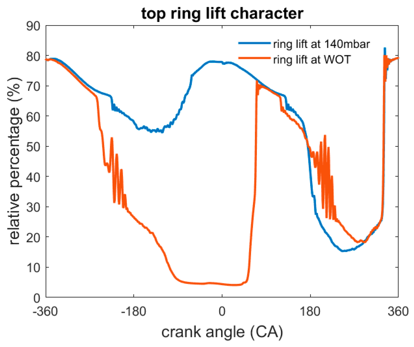
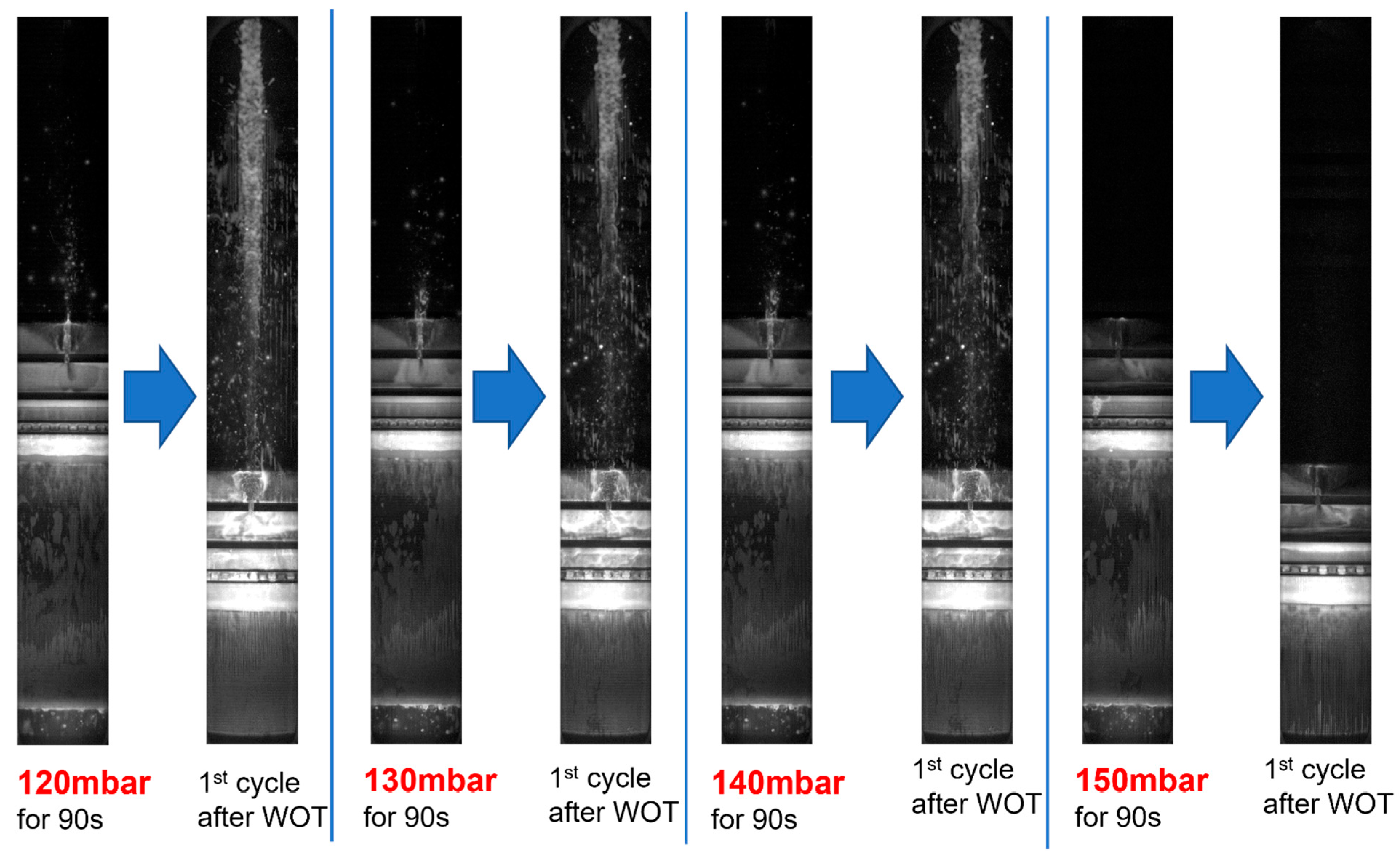
4.2.1. The Character Change across the Blowby Separation Line

Similar to the massive oil upwards transport at low load, the blowby separation line is also the regulating factor of the drastic change of oil behavior when changing from low to high load (Figure 10). The intake pressure of 150 mbar is the blowby separation line at 2000 rpm. Running under this load can result in massive oil upwards transport to even generate oil droplets through the top ring gap. The experiment maintained same 90 s time duration of low load before switching to WOT. With the increase of intake pressure, both the spike of oil release at the first expansion cycle and oil droplets during low load suddenly disappeared when reaching the 150 mbar blowby separation line. For the three tests with the spike oil release, the amount of oil released has no significant different in the visual observation.
The oil accumulated in the top ring groove and second land is actually the oil source for the spike leakage. Given 90 s, enough time, it has already reached equilibrium and provide similar oil source available to leak out. When running above the blowby separation line, suppressed oil upwards transport cannot feed enough oil into the top ring groove region. So, even though the pressure and ring lift mechanisms stated above when changing to high load still exists, the lack of oil source eliminated the spike increase of LOC.

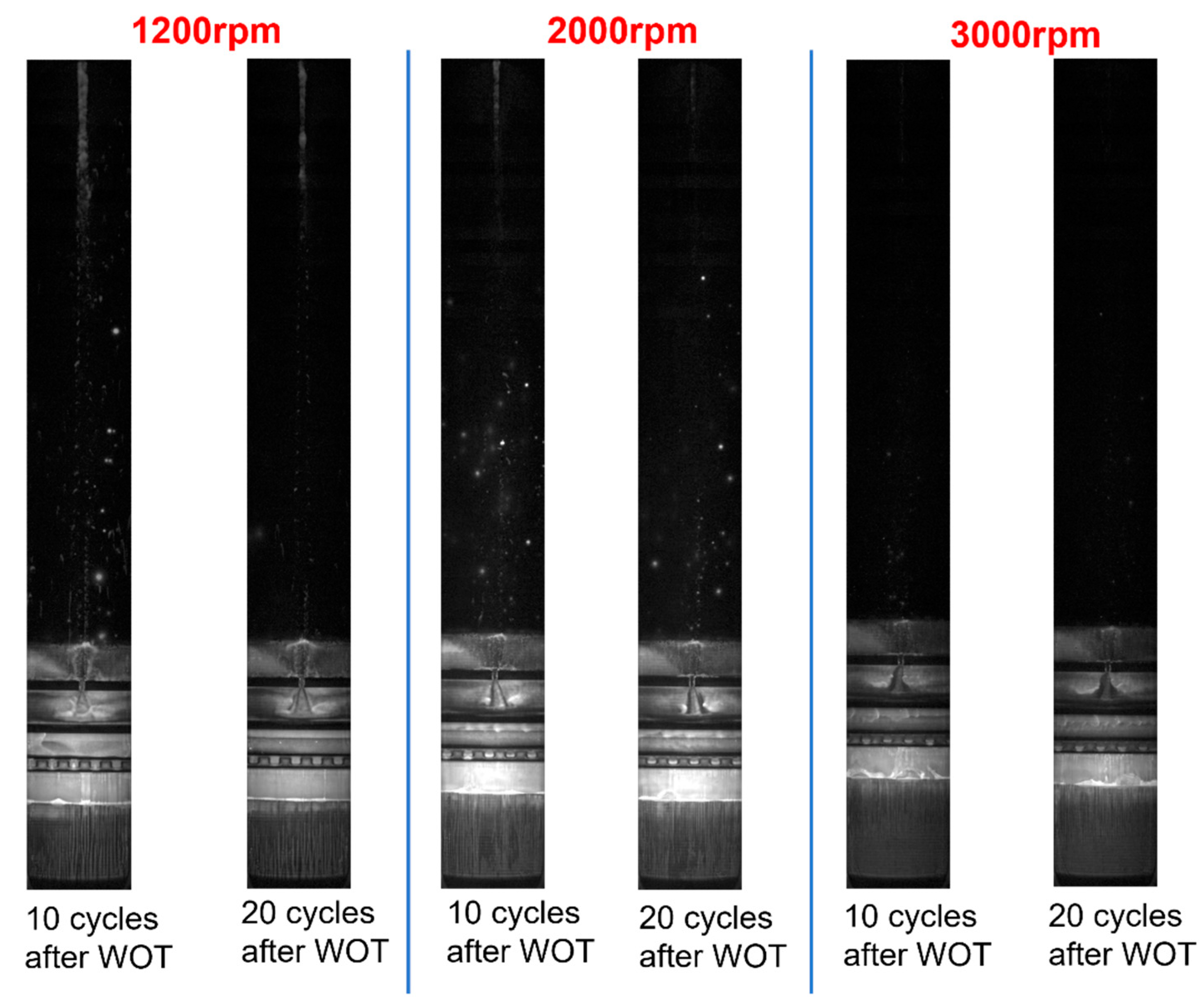
4.2.2. The Effect of Engine Speed

Knowing the blowby separation line’s importance, the experimental study focused on the engine speed’s effect was carried out at 140 mbar under this separation line for all the tested engine speeds. Time duration of low load was 90 s for all the tests. This time duration can guarantee the oil upwards transport already reached equilibrium in all the piston lands and grooves.
The overall trend with the change of speed is very clear that, the increase of engine speed can reduce both the oil upwards transport at low load and the spike of oil release after changing to WOT. Even though a lower engine speed can introduce fewer engine cycles to transport oil in the same time, after reaching equilibrium, a lower engine speed can result in more oil accumulated on each piston land [23]. As shown in Figure 11, after changing to the same load for 90 s, more oil droplets through the top ring gap as well as more oil in the second land can be observed at lower engine speeds. This provides more oil source to be released and explained an increased oil amount observed on liner when changing to WOT.
Furthermore, the increased oil source results in longer time to be cleaned when running at high load. Shown in Figure 12, at the 10th and 20th expansion cycle after WOT, the 1200 rpm’s test can still have much oil left on the liner, indicating still some oil accumulated around the top ring groove needs to be cleaned. At 3000 rpm, when the engine running 10 cycles after WOT, it can be seen there is already little oil attached on liner and almost no oil left at the 20th cycle.
Thus, the worst case would be concluded as running at the closed throttle condition at a lower engine speed for long time, and then suddenly change to high load high speed at the same time. When running under the blowby separation line at a lower speed, the increased oil accumulation is providing more sources for the leakage when changing to high load. If increasing the speed at the same time, the reduced oil accumulation can expand the amount of oil available to leak out. With the mechanism leaking oil unchanged with the change of speed, this operation can suffer from the worst LOC.

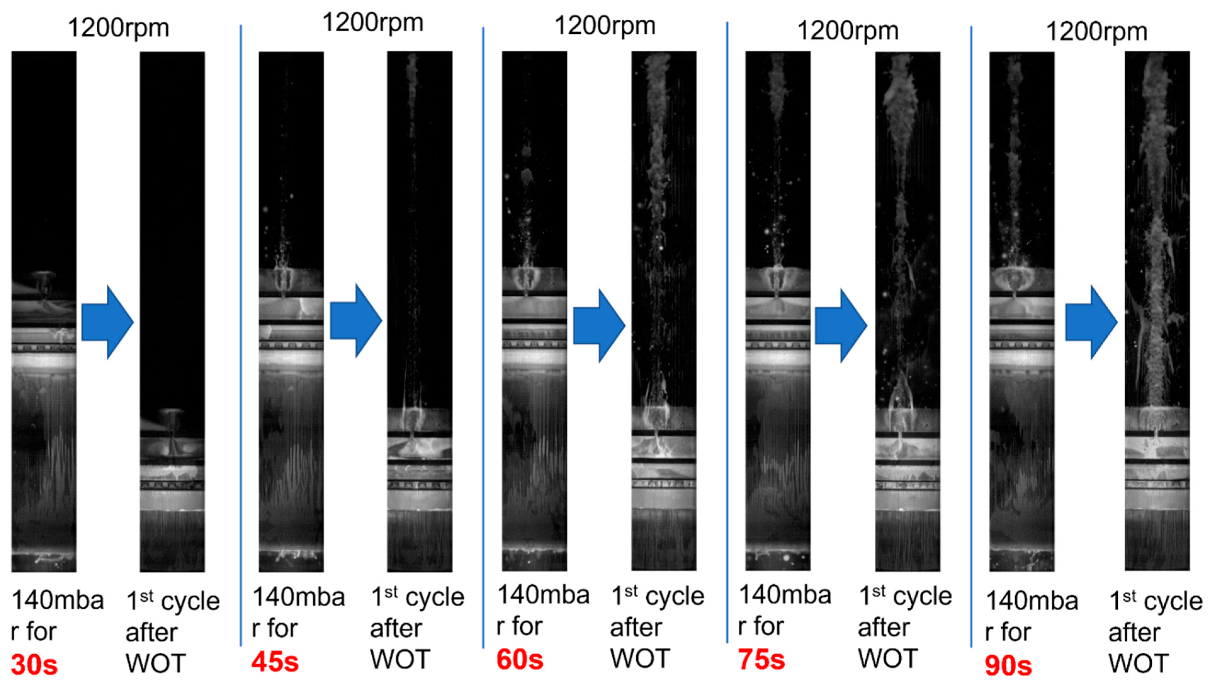
4.3. Time Duration at Low Load

In the test stated above, the time duration of low load period was all set as 90 s, making sure the oil upwards transport reaching equilibrium. However, in real world operation, the length of time operating under low load varies. This section shows the result of running the engine at low load for different time duration, ranging from 30 s to 90 s, and then switched to WOT.
As shown in Figure 13, with the increased time running at 1200 rpm 140 mbar condition, more oil can be transported into top ring groove. After decreasing the load for 30 s, even though the leakage from OCR can hit the second ring, the pumping effect has not experienced enough time to fill the upper regions, with no oil droplets can be observed through top ring gap. Furthermore, the second land is relatively clean of oil. At this moment, without oil source, the transient to WOT cannot result in the spike oil leakage.
As a result, running at negative blowby for longer time can transport more oil to the top ring groove and second land [9]. This oil served as the source to be leaked and resulted in a higher spike of oil leakage when changing to WOT. Figure 14 at a different engine speed 2000rpm shows the similar trend.

4.4. The Elimination of Spike Oil Leakage

4.4.1. Operation: Gradually Increase the Engine Load

Instead of suddenly increasing the engine load from under the blowby separation line to the highest available within one engine cycle, a gradual increase of engine load was studied as well. This operation was found effective to reduce the spike of oil leakage.
Figure 15a,b show the result of two operations to increase engine load with the same boundary conditions, running at 140 mbar for 90 s. At the first cycle after 90 s, the load was increased to an absolute intake pressure of 350 mbar instead of WOT. In this expansion stroke, only a small amount of oil was observed left on the liner. Moreover, no vortex below the top ring gap was observed in the late compression stroke. In the continued time, this oil leakage only continued for three engine cycles and disappeared in the 5th expansion stroke. After that, the engine load was further increased to WOT at a rate of 100 mbar per cycle. This is a safe operation as no oil left on liner was observed. In addition, after the engine was running at 350 mbar for five cycles, even directly increasing the load to WOT within one cycle can neither result in oil left on liner, as observed in the experiment as well.
In this engine operation, the oil leakage was reduced to a much smaller amount and lasted for only 3 cycles (Figure 15a), compared to more than 20 cycles when changing to WOT within one cycle (Figure 15b). This is mainly achieved by recycling oil back into lower regions instead of shooting oil to the liner, which is a bad path and leaked into combustion chamber.

4.4.2. Path to the Liner and Piston Land

Discussed in Section 4.1, the direct oil shooting from inside top ring groove to the liner is a major path for the oil leakage. It can be prevented through a gradual increase of load. Figure 16 shows the different oil behavior at early expansion stroke. With a high pressure inside top ring groove, the force applied on oil can push it into hitting the liner and even spread in the nearby region. When the pressure reduced, the force is only able to push the oil back into second land without travelling far enough to reach the liner. In addition, the oil pushed back into second land is not able to bridge to the liner either without vortex gas flow at a relatively low load. This is a good path to recycle the oil back into lower regions. Figure 17 is using a cartoon to demonstrate this phenomenon.
The high pressure can generate strong vortex below top ring gap. When this region is filled with oil mist, bridging oil to the liner can happen. Figure 18 shows the comparation of a magnification view at TDC at late compression. When the pressure only reached 350 mbar, even though the pressure through top ring gap is higher than the second ring, the gas flow is not strong enough to generate a vortex, as it stopped when reaching the second ring without horizontal movement. Thus, even though there is large amount of oil pushed from the top ring groove into the second land, the elimination of vortex can prevent a strong bridging to the liner. At the same time, as a load above the blowby separation line, this positive blowby can recycle oil back into lower regions, providing a much safer condition for further increasing the load.
Lastly, as the load is not high enough to push the top ring sitting down to the lower flank, the interface between the ring and groove at the upper flank will not open either. Even though the secondary motion can still move the piston towards thrust side, the oil squeezed out from the groove was not observed. Thus, all the three paths for oil to leak out can be reduced.

5. Conclusions

After the engine running under the blowby separation line for a long enough time, typically around 30 s, a sudden switch to high load can result in a spike oil leakage on the liner in the first several expansion strokes. The source is the oil accumulated inside top ring groove during the low load condition. When increasing the load, it can be triggered to leak out through three major paths: directly pushed out to the liner through the gap, high pressure induced bridging in second land and oil squeezed out due to the secondary motion. It can result in a spike increase of LOC and then gradual drop back to a relatively low level, when the oil inside top ring groove becomes clean of oil.
When increasing the load slowly, it can reduce the amount of oil leakage effectively by pushing the oil back into the second land instead of touching the liner. This is a better path to recycle the oil back into crankcase which can reduce the spike of LOC consequently.
A practical implication of this work is on the calibration of the engines. To reduce transient LOC, always maintaining a positive blowby is the key to avoid excessive oil leakage into the ring pack. If a zero blowby condition is unavoidable, one solution to prevent elevated LOC is to reduce the time running under the blowby separation line. Finally, a gradual increase of load can help reduce the spike of OE increase when compared with a sudden change.

Author Contributions

Design and preparation of the experiment, M.L.; Experimental investigation and modeling calculation, M.L.; writing the manuscript, M.L.; Supervising and revising the manuscript, T.T. All authors have read and agreed to the published version of the manuscript.

Funding

This work was sponsored by Mercedes-Benz and the Consortium on Lubrication in Internal Combustion Engines in the Sloan Automotive Laboratory, Massachusetts Institute of Technology. The consortium members were Mahle, Shell, Rolls-Royce Solutions, Toyota, Volkswagen Group, Volvo Trucks and Weichai Power.

Data Availability Statement

Not applicable.

Acknowledgments

This work was sponsored by Mercedes-Benz and the Consortium on Lubrication in Internal Combustion Engines in the Sloan Automotive Laboratory, Massachusetts Institute of Technology. The consortium members were Mahle, Shell, Rolls-Royce Solutions, Toyota, Volkswagen Group, Volvo Trucks and Weichai Power. The authors greatly thank all the member for the corporation.

Conflicts of Interest

The authors declare no conflict of interest.

Nomenclature

LOCLubricating Oil Consumption
2D-LIF2D Laser Induced Fluorescence
OCROil Control Ring
TPOCRThree-Piece Oil Control Ring
OEOil Emission
SISpark Ignited
PMParticulate Mass
PNParticulate Number
GPFGasoline Particulate Filter
DPFDiesel Particulate Filter
RDEReal Driving Emission
WOTWide Open Throttle
BDCBottom Dead Center
TDCTop Dead Center
FPGAField-Programmable Gate Array

References

  1. Cheng, W.K.; Hamrin, D.; Heywood, J.B.; Hochgreb, S.; Min, K.; Norris, M. An Overview of Hydrocarbon Emissions Mechanisms in Spark-Ignition Engines. SAE Technical Paper 932708. 1993. [Google Scholar] [CrossRef]
  2. Mayer, A.; Czerwinski, J.; Kasper, M.; Ulrich, A.; Mooney, J.J. Metal Oxide Particle Emissions from Diesel and Petrol Engines. Technical Paper 2012-01-0841. 2012. [Google Scholar] [CrossRef]
  3. Leach, F.; Chapman, E.; Jetter, J.J.; Rubino, L.; Christensen, E.D.; John, P.C.S.; Fioroni, G.M.; McCormick, R.L. A Review and Perspective on Particulate Matter Indices Linking Fuel Composition to Particulate Emissions from Gasoline Engines. SAE Int. J. Fuels Lubr. 2021, 15, 3–28. [Google Scholar] [CrossRef]
  4. Jonson, J.E.; Borken-Kleefeld, J.; Simpson, D.; Nyíri, A.; Posch, M.; Heyes, C. Impact of excess NO x emissions from diesel cars on air quality, public health and eutrophication in europe. Environ. Res. Lett. 2017, 12, 094017. [Google Scholar] [CrossRef]
  5. Premnath, V.; Khalek, I.; Morgan, P.; Michlberger, A.; Sutton, M.; Vincent, P. Effect of Lubricant Oil on Particle Emissions from a Gasoline Direct Injection Light-Duty Vehicle. SAE Technical Paper 2018-01-1708. 2018. [Google Scholar] [CrossRef]
  6. Schwanzer, P.; Schillinger, M.; Mieslinger, J.; Walter, S.; Hagen, G.; Märkl, S.; Haft, G.; Dietrich, M.; Moos, R.; Gaderer, M.; et al. A Synthetic Ash-Loading Method for Gasoline Particulate Filters with Active Oil Injection. SAE Int. J. Engines 2021, 14, 493–505. [Google Scholar] [CrossRef]
  7. Turnbull, R.; Dolatabadi, N.; Rahmani, R.; Rahnejat, H. An assessment of gas power leakage and frictional losses from the top compression ring of internal combustion engines. Tribol. Int. 2020, 142, 105991. [Google Scholar] [CrossRef]
  8. A Technical Summary of Euro 6/VI Vehicle Emission Standards. Available online: https://theicct.org/publication/a-technical-summary-of-euro-6-vi-vehicle-emission-standards/ (accessed on 1 July 2016).
  9. Li, M.; Tian, T. Effect of Blowby on the Leakage of the Three-Piece Oil Control Ring and Subsequent Oil Transport in Upper Ring-Pack Regions in Internal Combustion Engines. Lubricants 2022, 10, 250. [Google Scholar] [CrossRef]
  10. Przesmitzki, S.; Tian, T. Oil Transport Inside the Power Cylinder During Transient Load Changes; SAE Technical Paper 2007-01-1054. SAE Trans. 2007, 652–667. [Google Scholar] [CrossRef]
  11. Przesmitzki, S.; Tian, T. An Experimental Study of the Time Scales and Controlling Factors Affecting Drastic Blow-by Increases during Transient Load Changes in SI Engines. SAE Technical Paper 2008-01-0794. 2008. [Google Scholar] [CrossRef]
  12. Ahling, S.; Tian, T. Oil Transport Phenomena during extreme load transients inside the power cylinder unit as investigated by HS-2DLIF (High-Speed 2D Laser-Induced Fluorescence). SAE Technical Paper 2019-01-2363. 2019. [Google Scholar] [CrossRef]
  13. Yilmaz, E.; Thirouard, B.; Tian, T.; Wong, V.W.; Heywood, J.B.; Lee, N. Analysis of Oil Consumption Behavior during Ramp Transients in a Production Spark Ignition Engine. SAE Technical Paper 2001-01-3544. 2001; 1828–1837. [Google Scholar] [CrossRef]
  14. Papadopoulos, I.; Becker, S.; Ehnis, H.; Kunzel, R.; Frommer, A. Influence of Oil Drain Holes on Oil Emission of a Turbocharged Gasoline Engine. SAE Int. J. Engines 2017, 10, 1948–1953. [Google Scholar] [CrossRef]
  15. Uhlig, B.P.; Kirner, C.; Preuss, A.-C.; Wachtmeister, G. Real-Time Measurement of the Piston Ring Gap Positions and Their Effect on Exhaust Engine Oil Emission. SAE Technical Paper 2018-01-5006. 2018. [Google Scholar] [CrossRef]
  16. Adelmann, J.; Becker, S.; Rabute, R.; Bruno, R. Optimized oil control ring design for emission reduction. Zylinderlaufbahn Kolben Pleuel 2018, 91–103. [Google Scholar]
  17. Berthome, V.; Chalet, D.; Hetet, J.-F. Consequence of Blowby Flow and Idling Time on Oil Consumption and Particulate Emissions in Gasoline Engine. Energies 2022, 15, 8772. [Google Scholar] [CrossRef]
  18. Zanghi, E. Analysis of Oil Flow Mechanisms in Internal Combustion Engines via High Speed Laser Induced Fluorescence ( LIF ) Spectroscopy. Master’s Thesis, Massachusetts Institute of Technology, Cambridge, MA, USA, 2014. [Google Scholar]
  19. Zanghi, E.; Tian, T. Development of a High Speed Laser Induced Fluorescence (HSLIF) System in a Single Cylinder Engine for Oil Transport Studies. SAE Technical Paper 2016-01-0642. 2016; 1. [Google Scholar] [CrossRef]
  20. Ahling, S. Elements of Lubricant Transport Critical to Piston Skirt Lubrication and to Leakage into the Piston Ring Pack in Internal Combustion Engines. Ph.D. Thesis, Massachusetts Institute of Technology, Cambridge, MA, USA, 2021. [Google Scholar]
  21. Tian, T. Modeling the Performance of the Piston Ring-Pack in Internal Combustion Engines. Ph.D. Thesis, Massachusetts Institute of Technology, Cambridge, MA, USA, 1997. [Google Scholar]
  22. Zhong, X.; Li, M.; Tian, T. Hybrid digital twin for conditional lubricant oil transport simulation and oil consumption prediction in internal combustion engines. J. Eng. Tribol. 2023, 13506501221144697. [Google Scholar] [CrossRef]
  23. Przesmitzki, S. Characterization of Oil Transport in the Power Cylinder of Internal Combustion Engines during Steady State and Transient Operation. Ph.D. Thesis, Massachusetts Institute of Technology, Cambridge, CA, USA, 2018. [Google Scholar]
Figure 1. Ring pack and test bench configuration: (a) demonstration of ring pack in the piston; (b) engine and optical configuration
Lubricants 11 00076 g001
Figure 2. Range of optical view.
Lubricants 11 00076 g002
Figure 3. Engine transient cycles in the experiments.
Lubricants 11 00076 g003
Figure 4. Oil transport in engine transient operations: (a) the expansion strokes before the transient, 1st, 2nd, 5th, 10th cycles after the transient; (b) oil on the liner up-scraped by the top ring.
Lubricants 11 00076 g004
Figure 5. Pressure distribution in WOT and 140 mbar.
Lubricants 11 00076 g005
Figure 6. Oil distribution pattern generated by the vortex induced by high speed jet flow from the top ring gap; red spiral is added to illustrate the vortex
Lubricants 11 00076 g006
Figure 7. Oil behavior around the top ring: (a) cross section of the top ring with a twist chamfer; (b) oil pushed out of top ring gap into the second land and combustion chamber.
Lubricants 11 00076 g007
Figure 8. Oil leakage from top ring groove at early expansion: (a) Wide open throttle with oil streaks from the ring–groove interface. The red box shows additional oil from the groove; (b) closed throttle no oil from the groove.
Lubricants 11 00076 g008
Figure 9. Top ring lift character.
Lubricants 11 00076 g009
Figure 10. Oil leakage at 2000 rpm different load.
Lubricants 11 00076 g010
Figure 11. Oil leakage at 140 mbar different engine speed.
Lubricants 11 00076 g011
Figure 12. Oil leakage at 10th and 20th cycles after WOT.
Lubricants 11 00076 g012
Figure 13. Oil transient behavior for different time length at 1200 rpm.
Lubricants 11 00076 g013
Figure 14. Oil transient behavior for different time length at 2000 rpm.
Lubricants 11 00076 g014
Figure 15. Oil leakage pattern between ramp and step transient: (a) The oil leakage from 1st cycle to 20th cycle during ramp transient; (b) The oil leakage from 1st cycle to 20th cycle during step transient.
Lubricants 11 00076 g015
Figure 16. Oil and gas interaction from the top ring gap during early expansion stroke for different loads: (a) WOT; (b) 350 mbar.
Lubricants 11 00076 g016
Figure 17. Demonstration of high pressure inside top ring groove push oil to the liner: (a) section view at the gap area. The red color is showing WOT condition. The green color is showing a 350 mbar low-load condition; (b) top view. The blue arrow represents high pressure inside groove.
Lubricants 11 00076 g017
Figure 18. Oil gas interaction in the second land of 350 mbar and WOT condition: (a) 350 mbar condition no vortex generated; (b) WOT condition strong vortex bridge oil to the liner.
Lubricants 11 00076 g018
Table 1. Engine Specifications.
TypeSpark Ignition 4 Valves
Bore86.6 mm
Stroke88.0 mm
Displacement0.511 L
Max specific power37.3 kW/L@5400 rpm
Max specific torque80 Nm/L@4200 rpm
LubricantSAE 0W20
Disclaimer/Publisher’s Note: The statements, opinions and data contained in all publications are solely those of the individual author(s) and contributor(s) and not of MDPI and/or the editor(s). MDPI and/or the editor(s) disclaim responsibility for any injury to people or property resulting from any ideas, methods, instructions or products referred to in the content.

