Article

Tribological Properties of Nano-ZrO2 and PEEK Reinforced PTFE Composites Based on Molecular Dynamics

1
Mechanical and Electronical Engineering College, Gansu Agricultural University, Lanzhou 730070, China
2
State Key Laboratory of Solid Lubrication, Lanzhou Institute of Chemical Physics, Chinese Academy of Sciences, Lanzhou 730000, China
*
Author to whom correspondence should be addressed.
Lubricants 2023, 11(5), 194; https://doi.org/10.3390/lubricants11050194
Submission received: 29 March 2023 / Revised: 23 April 2023 / Accepted: 24 April 2023 / Published: 27 April 2023

Abstract

:
Polytetrafluoroethylene (PTFE) is a polymeric material with excellent self-lubricating properties. In this study, in order to improve the wear resistance of PTFE, the PTFE matrix was filled with soft-phase polyetheretherketone (PEEK) particles and hard-phase nano-ZrO2 particles in varying volume ratios. A linear reciprocating friction tester was used to test the tribological properties of the PTFE composites. Optical microscopy (OM) and scanning electron microscopy (SEM) were utilized to observe the formation and evolution of the transfer film on the surface of the counterpart metal during the friction process. Molecular dynamics simulation software (Materials Studio MS) was used to simulate and analyze the frictional behavior between the molecular structures of PTFE composites and the counterpart iron atoms on a microscopic scale. The results showed that the uniformity and firmness of the transfer film had an important influence on the wear resistance of the material. PEEK and ZrO2 nanoparticles were able to improve the firmness and formation rate of the transfer film, respectively, resulting in significant improvement in the wear resistance of PTFE (volume wear rate reduced from 7.7 × 10⁻⁴ mm3/Nm for pure PTFE to 1.76 × 10⁻⁶ mm3/Nm for nano-ZrO2/PEEK/PTFE). Molecular dynamics simulations revealed that the poor wear resistance of PTFE was due to significant interlayer slippage within its molecular chains. PEEK molecular chains could effectively adsorb PTFE molecular chains and formed a strong bond. ZrO2 nanoparticles also contributed to the overall stability of the PTFE matrix. Both soft and hard fillers significantly inhibited interlayer slippage between PTFE molecular chains, enhancing the shear deformation resistance of the material and thus improving the wear resistance of PTFE composites.

1. Introduction

Polytetrafluoroethylene (PTFE) is a polymer composed of -[-CF2-CF2-]-n molecular chains that exhibit remarkable properties, such as resistance to high temperatures, chemical corrosion, and biocompatibility, as well as excellent self-lubricating properties. As a result, PTFE is widely used as a solid lubricant in various industries, including aerospace, marine equipment, medical devices, and other areas [1,2]. However, PTFE’s limited wear resistance presents a considerable barrier to the material’s use in a wider variety of applications. Because of this, researchers have focused on improving the wear resistance of PTFE by incorporating improved fillers, such as graphite, molybdenum disulfide, fibers, and other similar materials, into the PTFE matrix. The abrasion resistance of PTFE composites has seen substantial advancement due to decades’ worth of research and development efforts [3,4,5,6,7,8,9,10,11]. In recent years, nanofillers have received more attention from researchers due to the large specific surface area and small size effect of nanoparticles compared to conventional fillers [12,13,14,15]. Burris et al. [12] investigated the use of PTFE composites containing 5% α-Al2O3 nanoparticles. They found that adding nanoparticles resulted in a four-order-of-magnitude reduction in volumetric wear rate compared to pure PTFE. Fei Li et al. [16] investigated the enhancement effect of ZnO nanoparticles on PTFE and showed that PTFE composites filled with 15% ZnO nanoparticles had the lowest volumetric wear rate.
As studies on this field have progressed, researchers have concluded that the surface energy and hardness of the polymer material are lower than those of the corresponding metal material with which it rubs against and that the microscopic concave and convex vertices of the metal surface continuously scraps the polymer surface and forms abrasive chips during the friction process. The debris detached from the polymer matrix temporarily rests on the friction interface. It makes a “three-body friction” motion with the friction of the specimen, where part of the debris is thrown out from the friction interface. In contrast, another part of the debris is gathered and adhered to the counterpart metal surface, forming a film called “transfer film”. Transfer films are crucial in friction systems because they act as a protective layer to prevent direct contact between the polymer and the metallic material. Many studies have been conducted on the properties of transfer films and their mechanism of action on the tribological properties of polymeric materials. There is a consensus that a thin and uniform layer of transfer film helps enhance the wear resistance of polymeric materials [17,18,19,20,21,22,23]. Urueña et al. [20] found that the volumetric wear rate of fluoropolymer during the stable friction phase was proportional to the cube of the thickness of the transfer film using an optical profilometer. Using atomic force microscopy, Gosvami et al. [21] found that zinc dioctyl phosphate could form a thick phosphorus oxide film on the metal surface during the friction process, which acted as an antiwear agent, and that the film gradually thickened and formed more complex structures, including branching, columnar, and blocky ones, as the contact time increased. Ye et al. [22,23] found that nanoalumina fillers enhanced the mechanical and thermal conductivity of the PTFE matrix and promoted the formation of a dense transfer film between the PTFE matrix and metal surface, thus improving the wear resistance of the composite. Schwartz [24] measured the bond strength of transfer films using cyanoacrylate bonded to copper plates, and the results showed that the wear resistance increased with the increase in the bond strength of the transfer film. In recent years, some scholars have applied molecular dynamics theory to the field of polymer tribology and achieved some theoretical results [25,26,27,28,29,30,31]. Onodera [26,27,28] used computational chemistry to simulate the process of transfer film formation. It was found that during friction, reactive gas molecules in the environment (e.g., oxygen) reacted chemically with hydrocarbons on the PTFE surface to produce new compounds, which, together with the polymer chains, formed the transfer film. In addition, the size and activity of the molecules were also found to have an essential effect on the formation and structure of the transfer film. Current researchers agree that a thin, uniform, and firmly adhered transfer film is beneficial for improving the wear resistance of polymeric materials.
In this study, PTFE composites were prepared by co-filling with soft-phase PEEK and hard-phase nano-ZrO2, and the tribological properties of the resulting composites were tested using a reciprocating sliding friction tester. The wear rate development and morphological characteristics of the transfer film during the friction process of the composites were analyzed and studied, and the synergistical enhancement effect of the two soft and hard particles on the PTFE matrix and the formation process of the transfer film was simulated at a microscopic scale using molecular dynamics methods. The mechanism of the effect of soft and hard fillers on the friction behavior and the transfer film properties of PTFE composites is discussed and summarized to provide a theoretical basis for the design and manufacture of polymer friction materials.

2. Materials and Methods

2.1. Preparation of PTFE Composites

The PTFE powder used in this study was POLYFLON M-18F (produced by Daikin Industries, Ltd., Osaka, Japan) with a density of 2.16 g/cm3 and an average particle size of 25 μm. The PEEK particles were Victrex PEEK 450 PF (manufactured by Victrex Ltd., Lancashire, UK) with a density of 1.3 g/cm3 and an average particle size of 50 μm. The nano-ZrO2 particles were XFI01 (produced by Jiangsu Xianfeng Nano Material Technology Co., Ltd., Nanjing, China) with a density of 5.89 g/cm3, an average particle size of 20–40 μm, and a specific surface area of 12.31 m2/g. The PTFE powder, PEEK particles, and nano-ZrO2 particles were formulated according to the recipe proportions shown in Table 1 using an electronic balance with an accuracy of 0.1 mg. To ensure that the fillers were fully and uniformly dispersed in the PTFE matrix, the prepared material powders were mechanically mixed using a high-speed airflow mixer and then sieved through a 150-mesh screen to remove large particle impurities formed by agglomeration. The material powders were cold-pressed into cylindrical specimens with a diameter of 6 mm using a hydraulic press at a pressure of 45 MPa in a dedicated mold. A pre-established temperature control program was used to sinter the pressed material into cylindrical specimens measuring 6 mm in diameter inside a furnace. The sintering temperature was set at 375 °C with a heating rate of 2 °C/min and a hold time of 120 min. Afterwards, the specimens were allowed to cool naturally to room temperature. To ensure adequate contact with the counterpart metal’s friction surface, the friction surface of the specimens was polished using 800-grit metallographic sandpaper. The specimens were then cleaned with acetone solvent in an ultrasonic cleaner, dried in a drying oven, and weighed using an electronic balance. All data were recorded to facilitate analysis. Steel materials of ASTM 1045 grade were selected for friction tests against the PTFE composites. In order to minimize the influence of surface roughness on the friction test results, the surface of the metal was polished and finished to an average surface roughness of 0.005 μm.

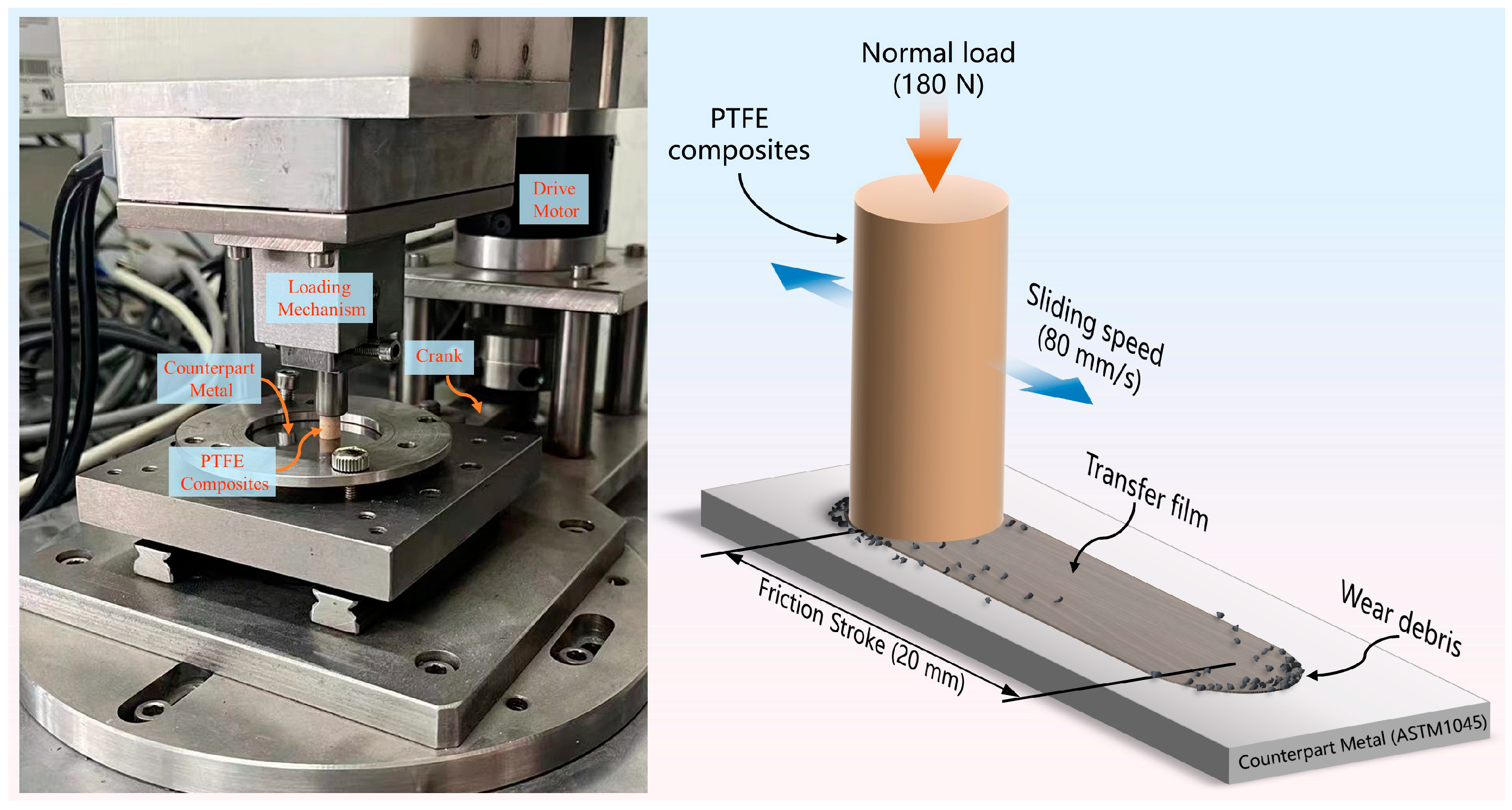
2.2. Friction and Wear Test

To examine the tribological characteristics of the PTFE composite, a linear reciprocating friction and wear tester (Model LSM-200, ZKKH Technology Development Co., Lanzhou, China) was employed, as shown in Figure 1. Before testing, the sample and counterpart metal surfaces were cleaned with acetone-soaked cotton balls. The specimens were loaded with a normal load of 180 N for a nominal contact pressure of around 6.3 MPa with an average linear velocity of 80 mm/s, and the ambient temperature was maintained at 25 °C. The total duration of the friction wear test for each specimen was 458.5 min (with a total stroke of 2200.8 m), and the test was split into seven separate trial phases (30 s, 1 min, 2 min, 5 min, 30 min, 2 h, or 5 h) to examine the progression of the PTFE composite’s tribological properties and the evolution of the morphological characteristics of the transfer film, as shown in Figure 2. After each independent stage of the friction test was completed, the specimen and the counterpart metal were carefully removed from the friction test machine. The specimen was weighed first to obtain the mass loss before and after the test, and the average volumetric wear rate K of the specimen in this stage was calculated according to Equation (1).
K = Δ m ρ N L
where Δm is the wear weight, ρ is the specimen’s actual density, N is the normal load applied to the sample, and L is the total sliding distance.
Then, the transfer film’s morphological characteristics on the counterpart metal’s surface were observed using an optical microscope (Axio Imager M2m, ZEISS, Jena, Germany), and its high-resolution digital image was obtained. After completing the above tests, the specimen and the counterpart metal were reinstalled in situ onto the friction test machine, and the next stage of the friction and wear test was continued. It was ensured that the specimen and counterpart metal surfaces were not damaged or contaminated during the disassembly, testing, and installation processes. After each specimen had completed a total of 458.5 min friction test, the final morphology of the specimen’s wear surface and the transfer film was observed using a scanning electron microscope (Quanta FEG450, FEI, Eindhoven, The Netherlands).

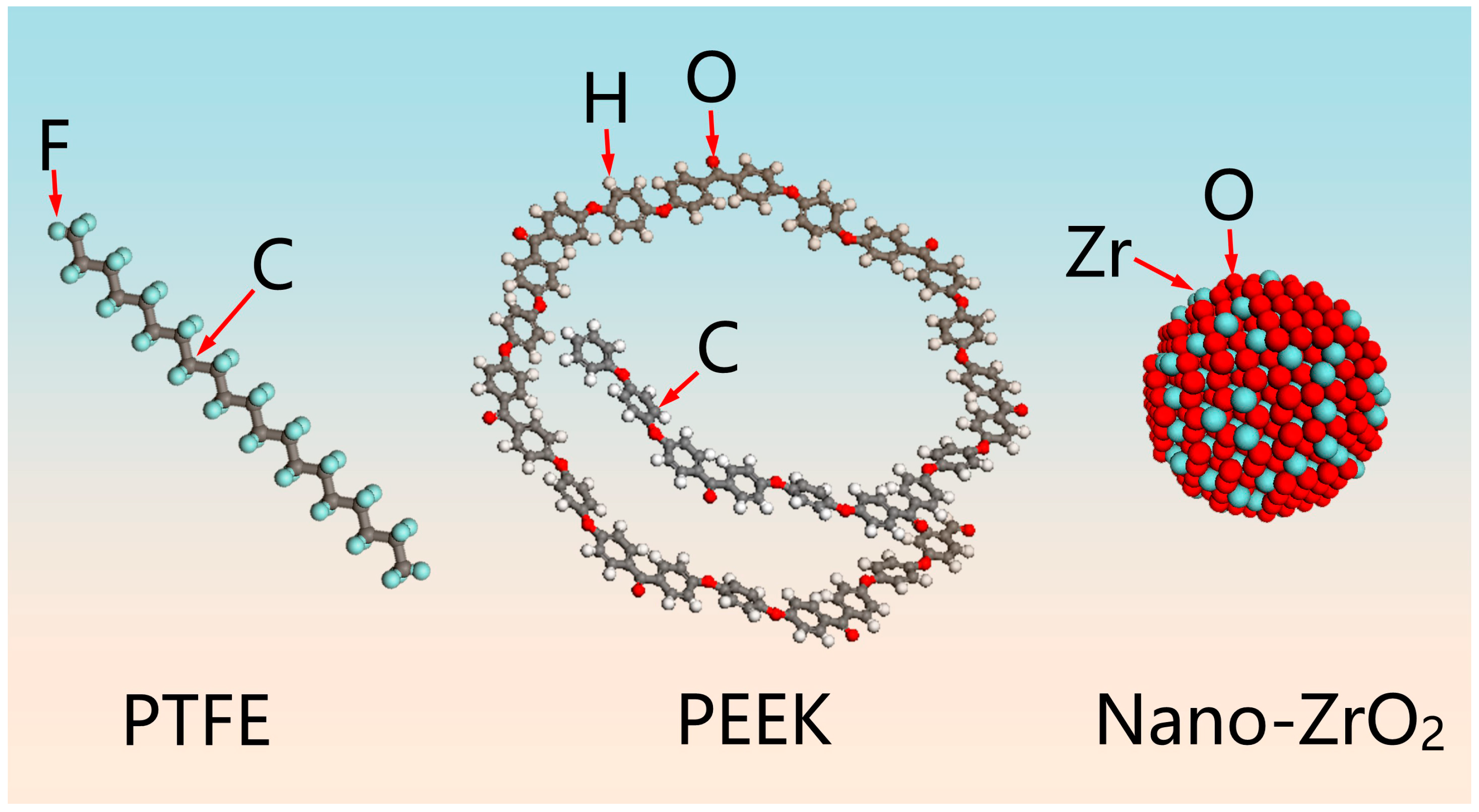
2.3. Construction Method of Molecular Dynamics Model for PTFE Composites

Molecular dynamics (MD) simulations provided a powerful tool to establish PTFE molecular chains containing different numbers of tetrafluoroethylene (CF2=CF2) units and computer their cohesion energy density. The results indicated that PTFE molecular chains with 10 -CF2-CF2- units exhibited a more stable cohesion energy value, as shown in Figure 3. The COMPASS force field was employed to optimize the structure of the PTFE molecular chain with 10 -CF2-CF2- units. The COMPASS force field includes intramolecular interactions (bonded energy Evalence) and intermolecular interactions (nonbonded energy Enon-bond). The sum of these two parts constitutes the total potential energy, where the nonbonded energy includes van der Waals energy and electrostatic energy. The overall potential energy of the molecular chain model was minimized using the conjugate gradient method, which reduces the excessive internal energy in the initial state and stabilizes the conformation [32]. The optimized PTFE molecular chains were used to construct the amorphous structure model of PTFE. A total of 30 pre-established PTFE polymer chains were randomly filled into a periodic lattice of size 6.0 nm × 6.0 nm × 12 nm according to Monte Carlo rules to form a PTFE amorphous model with a target density of 2.2 g/cm3. The optimization process eliminated intermolecular singular forces and unreasonable conformations. The amorphous cell calculation module is designed to calculate the properties of amorphous structures, such as the density and structure factor, and is helpful for simulating systems with disordered structures. This simulation utilized a canonical ensemble (with a fixed number of particles, volume, and temperature (NVT)) with a simulation temperature of 298 K, standard atmospheric pressure, and a simulation duration of 10 ps.
The PEEK molecular chain model containing 30 benzene ring structures was constructed using the same method described earlier, and the resulting structures were optimized, as depicted in Figure 3. The optimized PTFE and PEEK molecular chain models were then utilized to construct an amorphous copolymer model consisting of one PEEK molecular chain and 30 PTFE molecular chains. The intrinsic density of the model was determined by the ratio of total mass to the volume of the simulation box (20 Å × 20 Å × 20 Å), and the simulated temperature was set to 298 K.
A molecular dynamics model of ZrO2 nanoparticles was constructed using the supercell structure of ZrO2 nanoparticles as the precursor with a particle diameter of 1 nm, as shown in Figure 3. The ZrO2 nanoparticle models were placed in optimized PTFE and PEEK/PTFE box structures, and the energy of the hybrid structure was minimized through optimization. The models were then subjected to structural relaxation under the NVT system until the whole system reached equilibrium. Finally, three-layer structure-limited shear molecular dynamics models of the nano-ZrO2/PEEK/PTFE and nano-ZrO2/PTFE composites were developed based on their respective mass ratios.

3. Results and Discussion

3.1. Effect of ZrO2 Nanoparticles and PEEK on the Tribological Properties of PTFE Composites

Four specimens were tested for frictional wear using a reciprocating friction tester. Figure 4 illustrates the variation of the volumetric wear rate and friction coefficient of the four materials during the friction process. Figure 4a shows that the volumetric wear rate of PTFE was initially as high as 7.7 × 10⁻⁴ mm3/Nm within the first 30 s of the friction experiment, which decreased to 2.9 × 10⁻⁴ mm3/Nm in the second stage. This indicated that pure PTFE had a straightforward process of fitting to the counterpart metal surface in the initial stage of the friction experiment. Therefore, the volumetric wear rate during this period was exceptionally high and unstable. During the steady friction phase, the volumetric wear rate of pure PTFE remained above 3 × 10⁻⁴ mm3/Nm. As a result, the pure PTFE specimens completed only six stages of friction wear testing (total friction time of 158.5 min and total friction distance of 760.8 m). A large volume of PTFE flake abrasive chips was continuously extruded from the friction interface during the friction process, as shown in Figure 5a. This phenomenon indicated an apparent interlayer slip motion between the molecular chains inside the PTFE matrix. This slip motion was caused by the repulsive force between the fluorine atoms surrounding the carbon–carbon molecular chain of PTFE and the fluorine atoms on other molecular chains. The volumetric wear rate of the PTFE composite filled with 10% PEEK exceeded 1 × 10⁻⁴ mm3/Nm in the first two stages. However, the volume wear rate decreased significantly thereafter, accompanied by the formation of filamentary abrasive chips, as shown in Figure 5b. Upon entering the stable friction stage, the volume wear rate of PEEK/PTFE decreased to less than 1 × 10⁻⁵ mm3/Nm. The addition of 8% ZrO2 nanoparticles significantly improved the wear resistance of the composites. During the initial friction stage, the volume wear rate of nano-ZrO2/PTFE was even lower than that of PEEK/PTFE, and at the stable friction stage, the volume wear rate of nano-ZrO2/PTFE was reduced to less than 1 × 10⁻⁵ mm3/Nm, slightly higher than that of PEEK/PTFE. The debris of both composites exhibited a powder-like morphology in the late friction stage, as depicted in Figure 5c. This indicated that PEEK and nano-ZrO2, dispersed in the PTFE matrix and acted as a skeleton support, improving the creep resistance, compressive strength, and hardness of the composites and thereby effectively inhibiting the interlayer slip between the PTFE molecular chains in the late friction stage.
The PTFE composites with the addition of 10% PEEK and 8% ZrO2 nanoparticles exhibited significant reduction in the volume wear rate during the friction process, particularly in the stable friction stage, which showed the best wear resistance among the four materials. Its volume wear rate was only 1.76 × 10⁻⁶ mm3/Nm, which was 204 times lower than that of pure PTFE in the final friction stage (3.6 × 10⁻⁴ mm3/Nm), 204 times lower than PEEK/PTFE (3.53 × 10⁻⁶ mm3/Nm), and 2.6 times lower than nano-ZrO2/PTFE (4.56 × 10⁻⁶ mm3/Nm). The abrasive chips produced by nano-ZrO2/PEEK/PTFE friction also exhibited powder-like morphology and smaller size than the nano-ZrO2/PTFE abrasive chips, as shown in Figure 5d. This indicated that the soft PEEK and hard nano-ZrO2 particles synergistically improved the antiwear performance of PTFE composites.
Figure 4b displays the average friction coefficients of the specimens at various friction stages. Due to the need for the friction surface of the specimen and the counterpart metal surface to rub together, all four specimens initially exhibited high friction coefficients and sharp fluctuation. After entering a stage of steady friction, the average coefficients of friction of the specimens gradually stabilized. PTFE had the lowest average coefficient of friction at 0.18. Compared to pure PTFE, the average friction coefficients of the other three composites increased to varying degrees. PEEK/PTFE demonstrated a stable average friction coefficient of approximately 0.2, whereas nano-ZrO2/PTFE exceeded 0.24. The average friction coefficient of nano-ZrO2/PEEK/PTFE was 0.22, which was between those of PEEK/PTFE and nano-ZrO2/PTFE. This indicated that both PEEK and ZrO2 nanoparticles increased the friction coefficient of PTFE composites to varying degrees. Hard debris produced by composites containing nanoparticles is more likely to have a scraping effect on the friction surface of the material and transfer film, resulting in an increase in the friction coefficient [18,33].

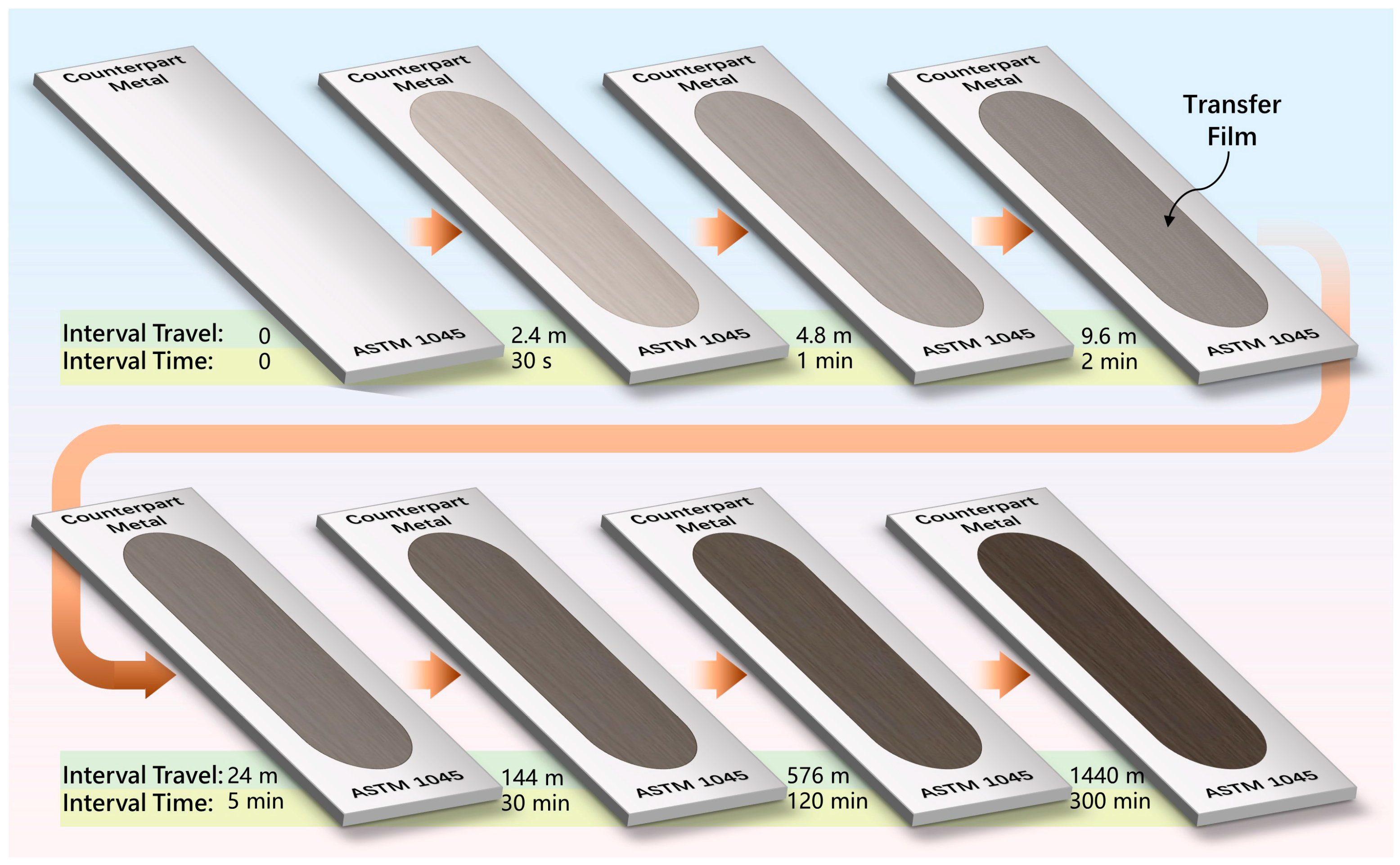
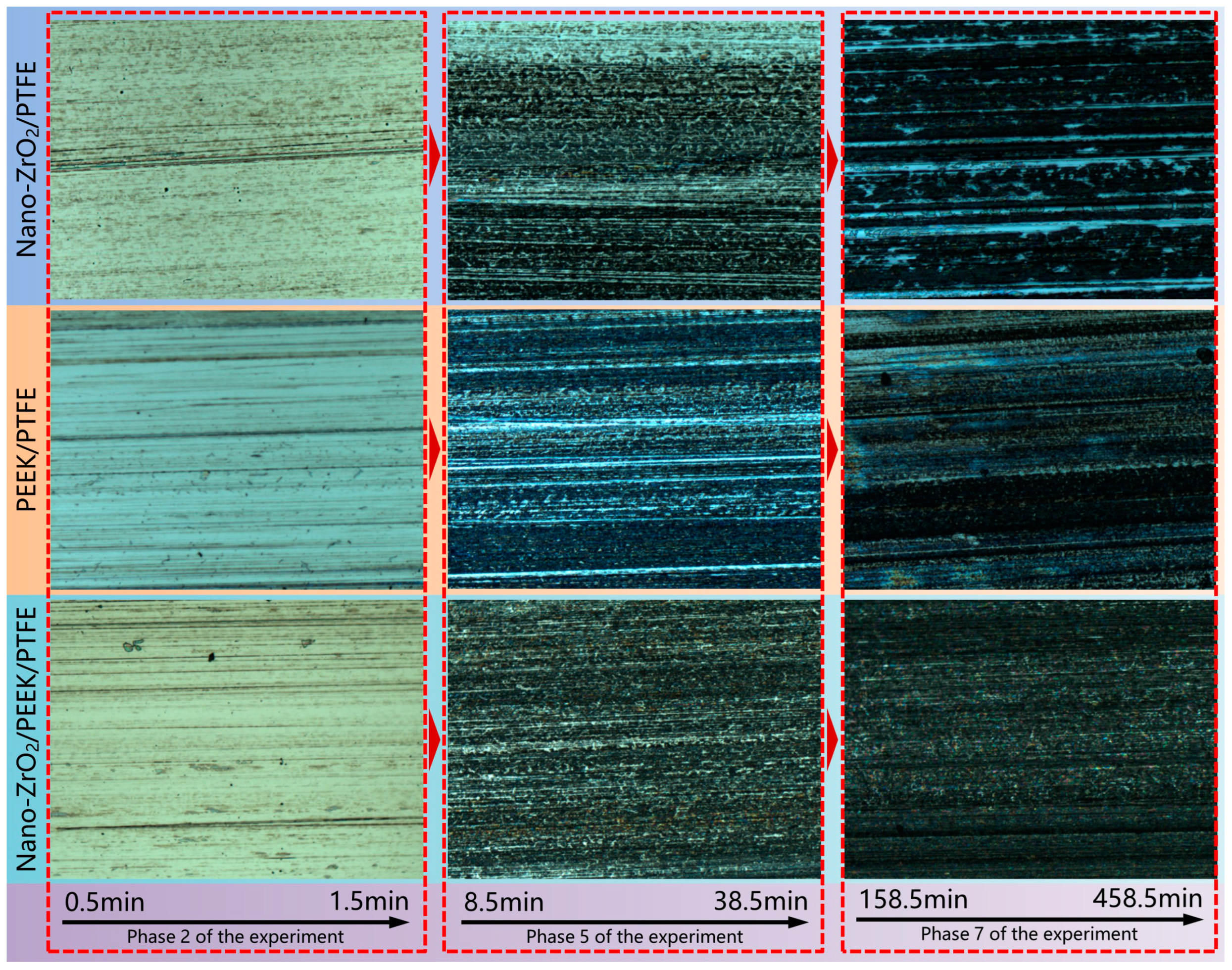
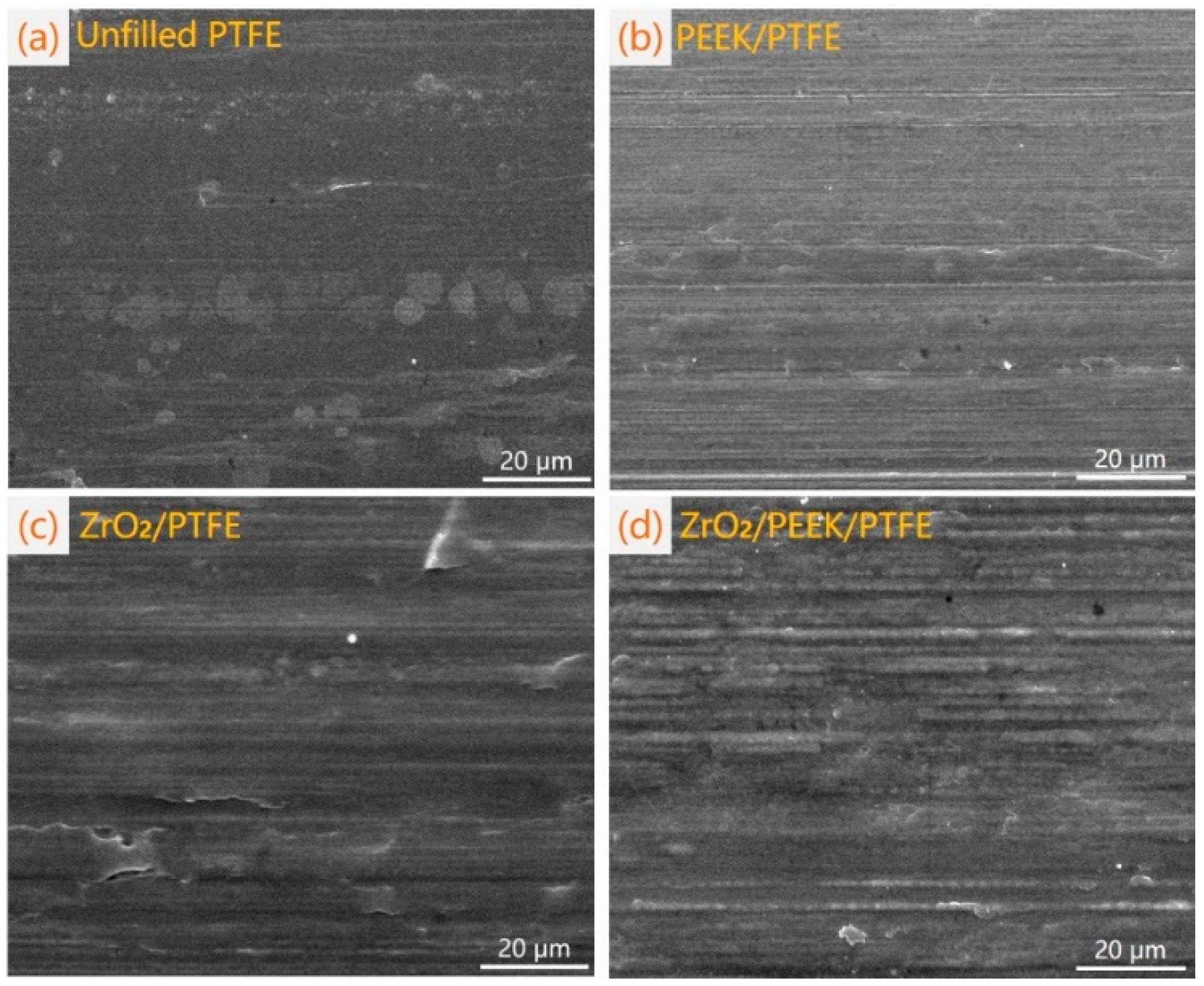
3.2. Effect of ZrO2 Nanoparticles and PEEK on Morphological Characteristics of PTFE Composite Transfer Films

During the friction process of polymers, some of the material near the friction surface of the specimen is transferred to the surface of the counterpart metal, with a portion deposited and adhered to the surface of the counterpart metal to form a thin film-like transition layer known as the “transfer film” [23,24]. The properties of the transfer film play a critical role in the tribological properties of polymeric materials, and various reinforced filler modifications significantly influence its development and properties. As shown in Figure 6, this study obtained optical images of the transfer film of PTFE composites filled with PEEK and ZrO2 nanoparticles adhering to the surface of the counterpart metal at different friction stages.
As can be seen in Figure 6, the transfer films formed by the three PTFE composites at the same friction stage exhibited different morphological characteristics. Even the morphological characteristics of the transfer film of the same PTFE composite sample evolved and changed as the friction test process progressed.
In the initial rubbing stage (0–1.5 min), a fine and uniformly distributed transfer film adhered to the surface of the counterpart metal rubbed with ZrO2/PTFE nanoparticles, and no large-size abrasive debris adhered to the entire counterpart metal surface. This indicated that the hard nanoparticles were beneficial in improving the film formation rate of the transfer film. This may be because the hard nanoparticles can effectively cut the larger-size debris at the early stage of friction, and these mechanically interlocked nanoparticles on the surface of the counterpart metal can anchor the moving debris at the friction interface, thus contributing to the rapid adhesion of the tiny debris to form the transfer film. There was a certain amount of banded abrasive debris on the surface of the counterpart metal rubbed with PEEK/PTFE in the same period. The long-axis direction of this banded abrasive debris showed a certain angle with the direction of friction motion, indicating that the reciprocal friction motion had a rolling and tearing effect on the abrasive debris, which made the size of the abrasive debris gradually decrease with the progress of the friction test. After the nano-ZrO2/PEEK/PTFE completed the stage 2 friction test, a small amount of abrasive debris was retained on its counterpart metal surface, while a relatively fine transfer film was formed in the local area, as shown in Figure 6. The volume wear rate of nano-ZrO2/PTFE in this period was lower than the other two composites.
In the transition friction stage (8.5–38.5 min), a transfer film completely covering the friction area was formed on the surface of the counterpart rubbed with nano-ZrO2/PEEK/PTFE, and the uniformity and continuity of the transfer film were better than those of the other two composites in the same period. At this stage, the transfer film formed by nano-ZrO2/PTFE also exhibited better uniformity and consistency. In contrast, the transfer film of PEEK/PTFE had not completely covered the entire counterpart metal surface. The volumetric wear rate of nano-ZrO2/PEEK/PTFE was the lowest within the transition friction stage, followed by nano-ZrO2/PTFE and then PEEK/PTFE.
During the stable friction phase (158.5–458.5 min), there were obvious scratch traces on the complete and homogeneous transfer film previously formed by the nano-ZrO2/PTFE composite. Newly generated abrasive debris could be observed in the groove area where the metal substrate was exposed. This was due to the accumulation and agglomeration of the hard debris detached from the friction surface of the specimen and the rolling motion of these debris on the friction interface as a friction body in the “three-body friction” system, which had a scraping effect on the transfer film and destroyed the integrity and uniformity of the formed transfer film. The disruption of the transfer film also led to a higher volumetric wear rate of the nano-ZrO2/PTFE composite than the other two materials during this phase. In contrast, the integrity and homogeneity of the PEEK/PTFE composite transfer film gradually increased during this period, suggesting that the PEEK particles were beneficial in enhancing the firmness of the transfer film. The transfer films of the nano-ZrO2/PEEK/PTFE composites maintained excellent integrity and uniformity during the stable friction phase, and the volumetric wear rate was the lowest among the three composites. This was because soft PEEK particles as the transition medium could effectively wrap the hard ZrO2 nanoparticles and connect with PTFE. Therefore, PEEK and nanoparticles enhanced the transfer film solidity and improved the film formation rate, respectively. Figure 7 shows the SEM images of the surfaces of the counterpart metal rubbed with each of the four materials at the end of the friction test. Figure 7a shows that the counterpart metal surface rubbed with pure PTFE did not form a transfer film at the end of the friction experiment. However, some flakes of abrasive debris were attached to the surfaces of the counterpart metal along the frictional sliding direction. PEEK/PTFE formed a complete transfer film on the surface of the counterpart metal at the end of the friction experiment, as shown in Figure 7b. Figure 7c,d shows that the surfaces of the counterpart metal after rubbing with nano-ZrO2/PTFE and nano-ZrO2/PEEK/PTFE were covered with a thicker transfer film but were also accompanied by a large number of plow traces, which were attributed to the scraping action of the hard nanoparticles.

3.3. Molecular Dynamics Simulation of Tribological Behavior of PEEK and Nano-ZrO2 Reinforced PTFE Composites

3.3.1. Restricted Three-Layer Structural Shear Friction Model of Fe Atomic Layer and Polymer

ASTM 1045 steel was chosen as the material for the counterpart metal that rubs against the PTFE composite during the friction process. Therefore, Fe was selected as the contact surface for the model when constructing the molecular dynamics friction system. Two rectangular supercell models of Fe atoms with identical dimensions (7 nm × 7 nm × 3 nm) were built in the friction system and placed at the top and bottom of the friction structure. The molecular dynamics models of PTFE, PEEK/PTFE, nano-ZrO2/PTFE, and nano-ZrO2/PEEK/PTFE were placed in the center of the lattice between the top and bottom Fe atomic structural models, forming a restricted shear friction model of Fe–polymer–Fe with a three-layer structure, as illustrated in Figure 8. Subsequently, the initial model of the established three-layer friction structure was optimized to reduce nonphysical contact between Fe atoms and the polymer and achieve dynamic equilibrium and energy optimization of the model [34]. The model was optimized through 100 simulation cycles using annealing temperatures ranging from 298 to 500 K under NVT system conditions, resulting in an equilibrium state for the entire system and acquiring a globally optimal structural model. The bottom layer of Fe atoms was fixed in place and was in contact with the underlying surface of the polymer model. The top layer of Fe atoms was then moved horizontally to the right at a speed of 5 m/s, resulting in a frictional motion between the bottom surface of the top Fe layer and the top surface of the polymer model. The simulation was conducted using the universal force field, and the three-layer friction system was subjected to continuous molecular dynamics simulations for 250 ps.

3.3.2. Molecular Dynamics Simulation of the Friction Behavior of PTFE Molecular Chains with Fe Atomic Layers

The frictional behavior between pure PTFE and the Fe atomic layer was simulated using molecular dynamics, as shown in Figure 9. During the first 200 ps, the upper structure of the PTFE matrix gradually moved to the right with the motion of the top Fe atomic layer, resulting in significant interlayer slippage. As the simulation progressed to 200 ps, the central structure of the PTFE matrix started to undergo shearing and tearing, leading to gradual delamination. Eventually, at 250 ps, the matrix was completely split into upper and lower parts. As shown in Figure 10, the distribution of atomic concentrations in the PTFE matrix revealed a high relative atomic concentration in the upper and lower regions of the matrix within 10 and 40 Å near the Fe atomic layer, while the concentration in the middle region was relatively lower. This phenomenon was attributed to the repulsion between the fluorine atoms that encased the carbon–carbon molecular chain backbone of PTFE, which resulted in inadequate capacity within the matrix to resist the shear forces generated by friction. As a consequence, the PTFE molecular chains experienced interlayer slip motion, leading to the aggregation of chains towards the friction region at the upper and lower ends of the matrix. Molecular dynamics simulations confirmed that this slip motion caused high volumetric wear rates and the generation of large abrasive debris.
Figure 11 shows the trend of the atomic temperature within the PTFE matrix along the model height. It was observed that the atomic temperature exceeded 315 K in the region from 15 to 33 Å within the matrix, forming a temperature plateau. The highest temperature of 320 K occurred near 29 Å within the matrix. The significant temperature increase in the PTFE matrix’s middle was due to the strong frictional interaction between the PTFE molecular chains and the resulting interlayer movement within the matrix. At the same time, the increase in the frictional temperature between the molecular chains enhanced the viscoelastic properties of the PTFE matrix. This manifested itself on a macroscopic scale as the pure PTFE materials were prone to adhesive wear during friction.

3.3.3. Molecular Dynamics Simulation of Tribological Properties of PEEK Particle Reinforced PTFE Composites

The molecular dynamics simulation process of the friction between the PEEK/PTFE composite model and Fe atomic layer is illustrated in Figure 12. The addition of 10% PEEK to the PTFE matrix significantly enhanced the composite material’s antishear deformation ability. Although the middle of the PEEK/PTFE matrix exhibited shear deformation later in the friction process, the overall structure remained stable without severe interlayer slip and delamination. By examining the distribution trend of atomic concentration within the PEEK/PTFE matrix along the model height, we discovered that the atomic concentration of PEEK/PTFE was 18% lower than that of PTFE at the same location in the region close to the Fe atomic layer within the matrix, as shown in Figure 10. However, in the middle region of the matrix, the atomic concentration of PEEK/PTFE was 13% higher than that of PTFE. During the simulated friction process, the highest internal temperature in the PEEK/PTFE matrix was 310 K, which was lower than that in the PTFE matrix, as illustrated in Figure 11. This is because, on the one hand, van der Waals and Coulomb forces resulted in stable adhesion forces between the PEEK and PTFE molecular chains. On the other hand, PEEK obstructed the repulsive forces between fluorine atoms on different PTFE molecular chains, effectively suppressing interlayer slip and mutual friction between PTFE molecular chains within the matrix, thereby reducing the friction temperature in the PEEK/PTFE matrix and weakening the tendency of molecular chains to aggregate from the middle region towards the upper and lower friction regions to some extent. Consequently, the addition of PEEK significantly improved the mechanical and tribological properties of the PTFE composite material.

3.3.4. Molecular Dynamics Simulation of Tribological Properties of Nano-ZrO2 Particle-Reinforced PTFE Composites

Figure 13 and Figure 14 depict the friction process between the Fe atomic layer and two nanocomposites, namely nano-ZrO2/PTFE and nano-ZrO2/PEEK/PTFE, simulated using molecular dynamics. The ZrO2 nanoparticles embedded within the polymer matrix were tightly wrapped by the PTFE and PEEK/PTFE molecular chains, respectively. Acting as a rigid skeleton, the nanoparticles supported the surrounding polymer molecular chains, anchoring them and enhancing the rigidity of the composite materials. Consequently, when subjected to the sliding and shearing effects of the Fe atomic layer on top, there was no interlayer slip of molecular chains within the matrix. The overall structure maintained excellent stability and integrity throughout the 250 ps friction process. Figure 11 demonstrates the effect of adding ZrO2 nanoparticles on the internal temperature of the matrix. The simulated temperature within the nano-ZrO2/PTFE and nano-ZrO2/PEEK/PTFE matrices was significantly lower than at corresponding positions within pure PTFE and PEEK/PTFE, with the internal temperature of the nano-ZrO2/PTFE matrix being below 300 K. The simulation results indicated that the addition of ZrO2 nanoparticles significantly enhanced the antishear deformation ability of the PTFE composite, effectively suppressing intermolecular friction and interlayer slip within the matrix and significantly improving the tribological properties of the PTFE composites. These results were consistent with those obtained from reciprocating friction and wear tests on PTFE composites filled with ZrO2 nanoparticles.

4. Conclusions

This study investigated the effects of soft-phase PEEK and hard-phase nano-ZrO2 particles on the frictional performance of PTFE composites. Molecular dynamics simulations were employed to investigate the microscopic frictional behavior of four polymer materials. Several conclusions were drawn as follows.
  • Adding soft-phase PEEK particles and hard-phase ZrO2 nanoparticles into the PTFE matrix could significantly enhance the wear resistance of the PTFE composites. However, the friction coefficient might also increase to varying degrees. During the steady friction stage, the nano-ZrO2/PEEK/PTFE composite exhibited the lowest volume wear rate of only 1.76 × 10⁻⁶ mm3/Nm, which was 204 times higher than the wear resistance of pure PTFE.
  • Both PEEK and nano-ZrO2 played essential roles in the morphological characteristics of the transfer film and its development behavior. The hard-phase ZrO2 nanoparticles could rapidly cut and minimize the debris and anchor them on the counterpart metal, thereby increasing the formation rate of the early transfer film. In the later friction stage, the ZrO2 nanoparticles could also scratch the already-formed transfer film, destroying its integrity. On the other hand, the soft-phase PEEK particles could wrap around the hard-phase nanoparticles, effectively reducing the damage of the hard-phase nanoparticles to the transfer film. Therefore, the nano-ZrO2/PEEK/PTFE simultaneously exhibited the dual advantages of quickly forming a transfer film in the early stage of friction and maintaining a complete, uniform, and firm transfer film in the stable friction stage.
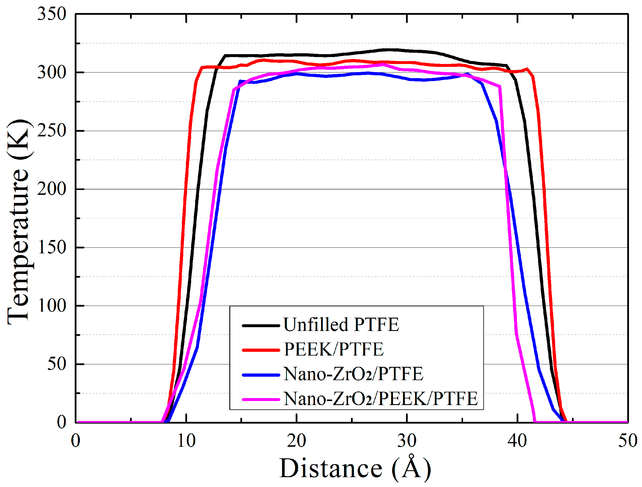
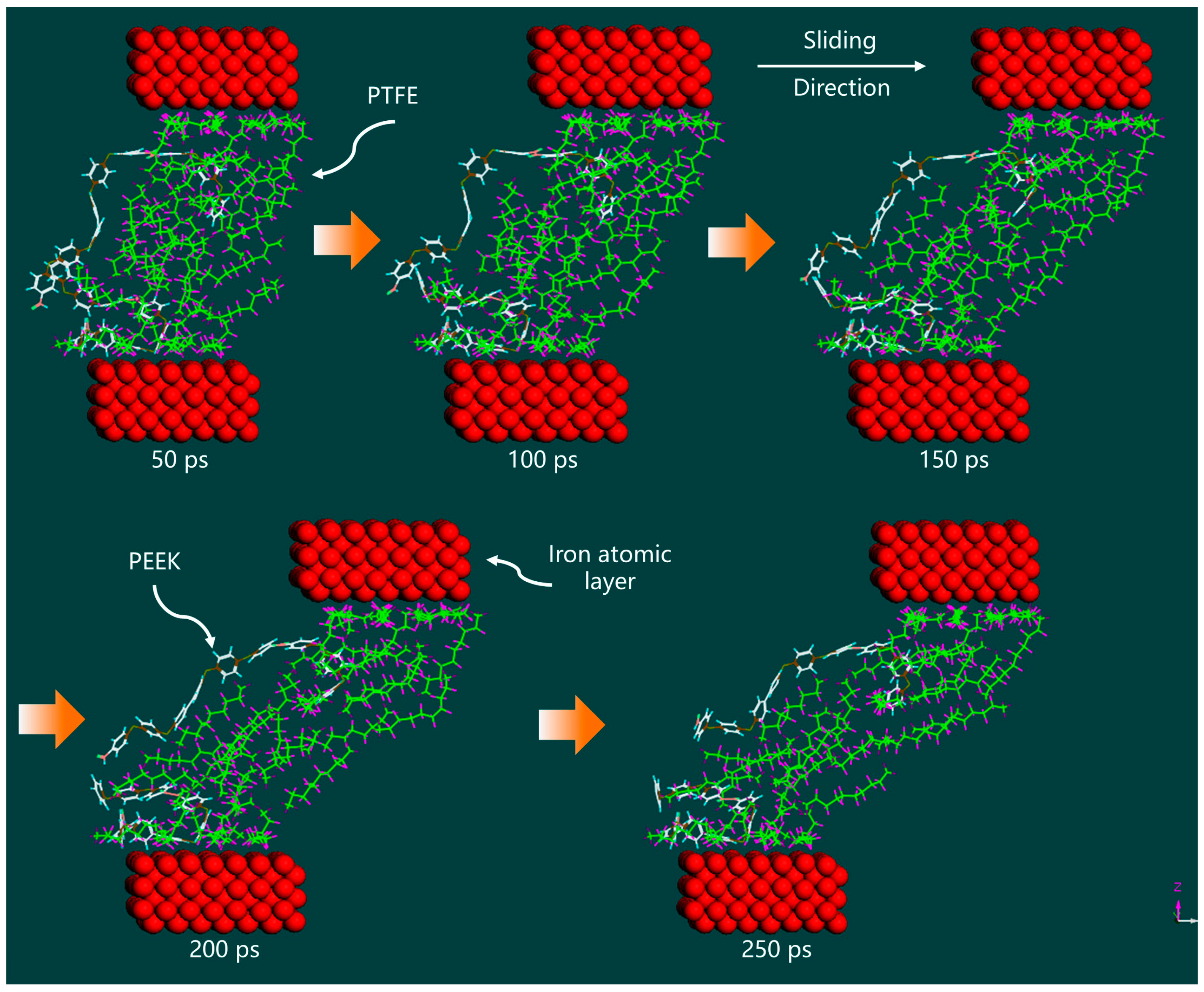
  • Molecular dynamics simulations were employed to investigate the frictional behavior of four PTFE composites at the microscopic scale. It was found that pure PTFE exhibited significant intermolecular frictional sliding between polymer chains within the matrix during friction, and the -[-CF2-CF2-]-n chains migrated towards the frictional region from the middle of the matrix. The simulated friction temperature in the middle of the matrix reached 320 K, which corresponded well with the occurrence of large-scale sheet-like debris and extremely high volumetric wear rate in PTFE observed in friction experiments. Adding PEEK and nano-ZrO2 particles significantly suppressed intermolecular frictional sliding between polymer chains within the matrix, reducing the friction temperature in the middle of the matrix, improving the material’s resistance to shear deformation and overall stability, and enhancing the frictional performance of the PTFE composite.

Author Contributions

Conceptualization, Y.Q.; methodology, Y.Q.; software, Y.Q. and Y.Z.; validation, P.Z., G.G. and X.Z.; formal analysis, Y.Q. and B.S.; data curation, G.G. and X.Z.; writing—original draft preparation, Y.Q.; writing—review and editing, Y.Q. and B.S.; funding acquisition, Y.Q., B.S. and Y.Z. All authors have read and agreed to the published version of the manuscript.

Funding

This research was funded by the Research Start-Up Projects Foundation of Gansu Agricultural University, grant number GAU-KYQD-2020-2; the National Natural Science Foundation of China, grant number 51965002; the Gansu Province Major Science and Technology Program Project, grant number 21ZD4FA010; the Young Doctor Fund of Gansu Provincial Department of Education, grant number 2022QB-073; and the Innovation Star Projects for Graduate Students of Gansu Province, grant number 2023CXZX-639.

Data Availability Statement

Not applicable.

Conflicts of Interest

The funders had no role in the design of the study; in the collection, analyses, or interpretation of data; in the writing of the manuscript; or in the decision to publish the results.

References

  1. Speerschneider, C.J.; Li, C.H. Some observations on the structure of polytetrafluoroethylene. J. Appl. Phys. 1962, 33, 1871–1875. [Google Scholar] [CrossRef]
  2. Bunn, C.W.; Cobbold, A.J.; Palmer, R.P. The fine structure of polytetrafluoroethylene. J. Polym. Sci. 1958, 28, 365–376. [Google Scholar] [CrossRef]
  3. Zhang, Z.Z.; Liu, W.J.; Xue, Q.J. Effects of various kinds of fillers on the tribological behavior of polytetrafluoroethylene composites under dry and oil–lubricated conditions. J. Appl. Polym. Sci. 2001, 80, 1891–1897. [Google Scholar] [CrossRef]
  4. Wan, Y.Y.; Xie, T.; Yu, J.W.; Dong, M. Behavior of interface migration of polymer matrix composites during friction. Mater. Rep. 2010, 24, 75. [Google Scholar]
  5. Lv, M.; Wang, L.; Liu, J.; Kong, F.; Ling, A.; Wang, T.; Wang, Q. Surface energy, hardness, and tribological properties of carbon-fiber/polytetrafluoroethylene composites modified by proton irradiation. Tribol. Int. 2019, 132, 237–243. [Google Scholar] [CrossRef]
  6. Gweon, J.H.; Joo, B.S.; Jang, H. The effect of short glass fiber dispersion on the friction and vibration of brake friction materials. Wear 2016, 362, 61–67. [Google Scholar] [CrossRef]
  7. Song, F.; Wang, Q.; Wang, T. Effects of glass fiber and molybdenum disulfide on tribological behaviors and PV limit of chopped carbon fiber reinforced polytetrafluoroethylene composites. Tribol. Int. 2016, 132, 237–243. [Google Scholar] [CrossRef]
  8. Trabelsi, M.; Kharrat, M.; Dammak, M. On the friction and wear behaviors of PTFE based composites filled with MoS2 and/or bronze particles. Trans. Indian Inst. Met. 2016, 69, 1119–1128. [Google Scholar] [CrossRef]
  9. Lin, Z.; Qu, T.; Zhang, K.; Zhang, Q.; Wang, S.; Wang, G. Modeling of contact temperatures and their influence on the tribological performance of PEEK and PTFE in a dual-pin-on-disk tribometer. Friction 2023, 11, 546–566. [Google Scholar] [CrossRef]
  10. Amenta, F.; Bolelli, G.; D’Errico, F.; Ottani, F.; Pedrazzi, S.; Allesina, G.; Lusvarghi, L. Tribological behaviour of PTFE composites: Interplay between reinforcement type and counterface material. Wear 2022, 510, 204498. [Google Scholar] [CrossRef]
  11. Wang, H.; Qi, X.; Zhang, W.; Dong, Y.; Fan, B.; Zhang, Y. Tribological properties of PTFE/Kevlar fabric composites under heavy loading. Tribol. Int. 2020, 151, 106507. [Google Scholar] [CrossRef]
  12. Burris, D.L.; Sawyer, W.G. Improved wear resistance in alumina–PTFE nanocomposites with regular shaped nanoparticles. Wear 2006, 260, 915–918. [Google Scholar] [CrossRef]
  13. Yuan, Q.; Gong, J.; Cao, W.H.; Wang, H.G.; Ren, J.F.; Gao, G. Tribological behaviour of PTFE composites filled with PEEK and nano-Al2O3. Tribol. Trans. 2018, 61, 694–704. [Google Scholar] [CrossRef]
  14. Yue, W.; Gong, J.; Yang, D.Y.; Gao, G.; Wang, H.G. Tribological behavior of nano-Al2O3-reinforced PPS-PTFE composites. Tribol. Trans. 2014, 57, 173–181. [Google Scholar] [CrossRef]
  15. Wang, Q.H.; Xue, Q.J.; Shen, W.C. The friction and wear properties of nanometre SiO2 filled polytetrafluoroethylene. Tribol. Int. 1997, 30, 193–197. [Google Scholar] [CrossRef]
  16. Lei, F.; Hu, K.A.; Li, J.L.; Zhao, B.Y. The friction and wear characteristics of nanometer ZnO filled polytetrafluoroethylene. Wear 2001, 249, 877–882. [Google Scholar] [CrossRef]
  17. Khare, H.S.; Moore, A.C.; Haidar, D.R.; Gong, L.; Ye, J.; Rabolt, J.F.; Burris, D.L. Interrelated Effects of Temperature and Environment on Wear and Tribochemistry of an Ultralow Wear PTFE Composite. J. Phys. Chem. C 2015, 119, 16518–16527. [Google Scholar] [CrossRef]
  18. Harris, K.L.; Curry, J.; Pitenis, A.A.; Rowe, K.G.; Sidebottom, M.A.; Sawyer, W.G.; Krick, B.A. Wear Debris Mobility, Aligned Surface Roughness, and the Low Wear Behavior of Filled Polytetrafluoroethylene. Tribol. Lett. 2015, 60, 2. [Google Scholar] [CrossRef]
  19. Nunez, E.E.; Polycarpou, A.A. The effect of surface roughness on the transfer of polymer films under unlubricated testing conditions. Wear 2015, 326–327, 74–83. [Google Scholar] [CrossRef]
  20. Urueña, J.M.; Pitenis, A.A.; Harris, K.L.; Sawyer, W.G. Evolution and wear of fluoropolymer transfer films. Tribol. Lett. 2015, 57, 9. [Google Scholar] [CrossRef]
  21. Gosvami, N.N.; Bares, J.A.; Mangolini, F.; Konicek, A.R.; Yablon, D.G.; Carpick, R.W. Mechanisms of antiwear tribofilm growth revealed in situ by single-asperity sliding contacts. Science 2015, 348, 102–106. [Google Scholar] [CrossRef] [PubMed]
  22. Ye, J.; Khare, H.; Burris, D. Quantitative characterization of solid lubricant transfer film quality. Wear 2014, 316, 133–143. [Google Scholar] [CrossRef]
  23. Ye, J.; Khare, H.; Burris, D. Transfer film evolution and its role in promoting ultra-low wear of a PTFE nanocomposite. Wear 2013, 297, 1095–1102. [Google Scholar] [CrossRef]
  24. Schwartz, C.J.; Bahadur, S. Studies on the tribological behavior and transfer film–counterface bond strength for polyphenylene sulfide filled with nanoscale alumina particles. Wear 2000, 237, 261–273. [Google Scholar] [CrossRef]
  25. Bai, S.; Onodera, T.; Nagumo, R.; Miura, R.; Suzuki, A.; Tsuboi, H.; Hatakeyama, N.; Takaba, H.; Kubo, M.; Miyamoto, A. Friction reduction mechanism of hydrogen- and fluorine-terminated diamond-like carbon films investigated by molecular dynamics and quantum chemical calculation. J. Phys. Chem. C 2012, 116, 12559–12565. [Google Scholar] [CrossRef]
  26. Onodera, T.; Park, M.; Souma, K.; Ozawa, N.; Kubo, M. Transfer–film formation mechanism of polytetrafluoroethylene: A computational chemistry approach. J. Phys. Chem. C 2013, 117, 10464–10472. [Google Scholar] [CrossRef]
  27. Onodera, T.; Kawasaki, K.; Nakakawaji, T.; Higuchi, Y.; Ozawa, N.; Kurihara, K.; Kubo, M. Effect of tribochemical reaction on transfer–film formation by polytetrafluoroethylene. J. Phys. Chem. C 2014, 118, 11820–11826. [Google Scholar] [CrossRef]
  28. Onodera, T.; Nunoshige, J.; Kawasaki, K.; Adachi, K.; Kurihara, K.; Kubo, M. Structure and function of transfer film formed from PTFE/PEEK polymer blend. J. Phys. Chem. C 2017, 121, 14589–14596. [Google Scholar] [CrossRef]
  29. He, E.; Wang, S.; Li, Y.; Wang, Q. Enhanced tribological properties of polymer composites by incorporation of nano-SiO2 particles: A molecular dynamics simulation study. Comput. Mater. Sci. 2017, 134, 93–99. [Google Scholar] [CrossRef]
  30. Chawla, R.; Sharma, S. A molecular dynamics study on Young’s modulus and tribology of carbon nanotube reinforced styrene-butadiene rubber. J. Mol. Model. 2018, 24, 96. [Google Scholar] [CrossRef]
  31. Deng, P.; Fan, B.; Qi, X.; Yang, Y.; Hao, X. Investigation of ptfe tribological properties using molecular dynamics simulation. Tribol. Lett. 2019, 67, 28. [Google Scholar] [CrossRef]
  32. Swope, W.; Andersen, H.; Berens, P.; Wilson, K. A computer simulation method for the calculation of equilibrium con-stants for the formation of physical clusters of molecules: Application to small water clusters. J. Chem. Phys. 1982, 76, 637–649. [Google Scholar] [CrossRef]
  33. Cherif, K.; Gueroult, B.; Rigaud, M. Al2O3–ZrO2 debris life cycle during wear: Effects of the third body on wear and friction. Wear 1997, 208, 161–168. [Google Scholar] [CrossRef]
  34. Tang, L.; Li, Y.; He, E.; Hao, M.; Ren, S. Molecular simulation of tribology behavior of nano ZnO/nitrile-butadiene rubber composites. Acta Mater. Compos. Sin. 2020, 37, 690–695. [Google Scholar]
Figure 1. Schematic diagram of the reciprocating friction structure.
Lubricants 11 00194 g001
Figure 2. Schematic diagram of segmented friction experiment.
Lubricants 11 00194 g002
Figure 3. Molecular dynamics model structures of PTFE, PEEK, and nano-ZrO2.
Lubricants 11 00194 g003
Figure 4. Tribological behaviors of PTFE composites filled with different volumes of PEEK and nano-ZrO2 particles: (a) the wear rate, (b) the friction coefficient.
Lubricants 11 00194 g004
Figure 5. The morphological characteristics of abrasive chips produced by PTFE composites: (a) unfilled PTFE, (b) PEEK/PTFE, (c) nano-ZrO2/PTFE, (d) nano-ZrO2/PEEK/PTFE.
Lubricants 11 00194 g005
Figure 6. Morphological characteristics of PTFE composite transfer film at different friction stages.
Lubricants 11 00194 g006
Figure 7. SEM images of the surfaces of the counterpart metal: (a) unfilled PTFE, (b) PEEK/PTFE, (c) nano-ZrO2/PTFE, (d) nano-ZrO2/PEEK/PTFE.
Lubricants 11 00194 g007
Figure 8. Molecular dynamics model of the three-layer friction structure of PTFE composites.
Lubricants 11 00194 g008
Figure 9. Molecular dynamics simulation of the friction process between unfilled PTFE and Fe atomic layers.
Lubricants 11 00194 g009
Figure 10. Distribution of the relative concentration of atoms within unfilled PTFE and PEEK/PTFE matrix.
Lubricants 11 00194 g010
Figure 11. Friction temperature distribution within the PTFE composite matrix.
Lubricants 11 00194 g011
Figure 12. Molecular dynamics simulation of the friction process between PEEK/PTFE and Fe atomic layers.
Lubricants 11 00194 g012
Figure 13. Molecular dynamics simulation of the friction process between nano-ZrO2/PTFE and Fe atomic layers.
Lubricants 11 00194 g013
Figure 14. Molecular dynamics simulation of the friction process between nano-ZrO2/PEEK/PTFE and Fe atomic layers.
Lubricants 11 00194 g014
Table 1. Formulation ratio of PTFE composites.
TitlePTFE (vol.%)PEEK (vol.%)Nano-ZrO2 (vol.%)
Pure PTFE10000
PEEK/PTFE90100
Nano-ZrO2/PTFE9208
Nano-ZrO2/PEEK/PTFE82108
Disclaimer/Publisher’s Note: The statements, opinions and data contained in all publications are solely those of the individual author(s) and contributor(s) and not of MDPI and/or the editor(s). MDPI and/or the editor(s) disclaim responsibility for any injury to people or property resulting from any ideas, methods, instructions or products referred to in the content.

