Article

The Effect of Steel Electropolishing on the Tribological Behavior of a Steel–Bronze Pair in the Mixed and Boundary Lubrication Regimes

1
Faculty of Mechanical Engineering and Naval Architecture, University of Zagreb, Ivana Lučića 5, 10000 Zagreb, Croatia
2
Metal Centre Čakovec, Bana Josipa Jelačića 22 D, 40000 Čakovec, Croatia
*
Author to whom correspondence should be addressed.
Lubricants 2023, 11(8), 325; https://doi.org/10.3390/lubricants11080325
Submission received: 6 July 2023 / Revised: 26 July 2023 / Accepted: 28 July 2023 / Published: 1 August 2023
(This article belongs to the Special Issue Advances in Surface Engineering and Tribology)

Abstract

:
Electropolishing at high current densities without agitation of the electrolyte results in a pitting phenomenon that produces dimple-like surface features. Although pitting is unfavorable in the electropolishing process, its effect on surface modification, such as surface texturing, has not been thoroughly investigated. Surface topography and chemical composition analyses of electropolished steel revealed surface pits and an oxide surface layer, indicating the presence of surface texture and coating. The resulting surface is characterized by negative skewness and high kurtosis values. The tribological behavior of the electropolished steel-bronze pair is investigated by evaluating coefficients of friction and bronze wear using sliding tests conducted in mixed and boundary lubrication regimes. The results are compared to those of the ground steel-bronze pair. In the mixed and upper range of the boundary lubrication regime, coefficients of friction reduction up to 30% and shorter running-in phases are observed for electropolished steel (electropolished steel μavg = 0.019 vs. ground steel μavg = 0.028). In contrast, the coefficient of friction increased in the lower range of boundary lubrication regime by 50% (electropolished steel μavg = 0.098 vs. ground steel μavg = 0.065). Electropolishing, as a cost- and time-effective method applicable to complex geometries, presents an alternative method for achieving surface modifications aimed at friction reduction and improved tribological behavior for non-conformal contacts in the boundary and mixed lubrication regimes.

1. Introduction

Surface modification of metal surfaces is often conducted to reduce wear and friction. Surfaces are usually modified by employing surface coatings or by altering surface topography. The change in surface topography is frequently achieved by producing a surface texture. Common techniques used for surface texturing include laser surface texturing (LST), electrochemical etching, and micro-machining [1,2]. Surface textures are characterized by micro-cavities with multiple beneficial functions: entrapment of wear debris, secondary oil effect, friction reduction, and an increase in the oil film thickness [3]. The influences of surface textures have been frequently investigated with the aim of friction and wear reduction in boundary and mixed lubrication regimes. Ali et al. [4] explored the use of textured surfaces in high-load boundary lubrication conditions. Textured surfaces reduced friction and contributed to the creation of an extra hydrodynamic lift effect. Vrbka et al. [5,6] investigated the effect of surface texturing in mixed lubricated non-conformal contacts. The authors observed that shallow micro-dents and textures increased the oil film thickness and the rolling contact fatigue life. Galda et al. [7] researched surfaces textured with different shapes. The spherical oil pockets increased the oil film thickness and reduced the coefficient of friction compared to the untextured surface. Gupta et al. chemically etched [8] and laser textured [9] spur gear teeth flanks, producing a dimpled surface. Results showed reduced wear and a significant decrease in vibration amplitudes. Besides the surface texturing techniques mentioned earlier, other techniques can produce surface textures, such as shot peening (shot blasting) and electropolishing. Li et al. [10] shot-peened specimens made of gear steel. A positive influence on the friction coefficient reduction was attributed to the dimpled surface, particularly if fine particle peening is used. Nakatsuji and Mori [11,12] investigated the electropolishing of medium carbon steel gears. The produced surface had many pores/pits and shallow dimples that encouraged the creation of the oil film, consequently improving the pitting durability by 50%.
Certain surface characteristics, such as kurtosis (Rku) and skewness (Rsk), can reduce friction. The symmetrical height distribution of a roughness profile indicates zero skewness, while predominant peaks and spikes on a surface result in positive skewness (Rsk > 0). In contrast, porous and dimpled surfaces with deep valleys are reflected in negative skewness (Rsk < 0). The kurtosis coefficient describes the sharpness of the probability density of the profile. If Rku < 3, the distribution curve is characterized by relatively few high peaks and low valleys. On the other hand, if Rku > 3, the distribution curve is characterized by many high peaks and low valleys [13]. A schematic representation of kurtosis and skewness is given in Figure 1. The influence of kurtosis and skewness was a topic of many investigations regarding surface texturing. Akamatsu et al. [14] investigated rolling bearing fatigue life with several surface texture types and found that bearings with higher negative skewness had a longer life. Sedlaček et al. [15] produced the textures by LST and concluded that when skewness is more negative while kurtosis is increasing, the coefficient of friction reduces. Krupka et al. [16] observed that shallow pits work as lubricant micro-reservoirs, while deep grooves cause oil film thickness reduction in mixed lubricated non-conformal contacts. Dzierwa [17] concluded that an increase in kurtosis and more negative skewness results in lower wear volume under dry sliding conditions in steel-steel contact. Senatore et al. [18] improved the tribological properties of lead bronze coating by producing a textured surface characterized by negative skewness (Ssk = −1.42) and high kurtosis (Sku = 5.68). Based on the literature overview, it can be concluded that surface topography designated by high kurtosis and negative skewness positively contributes to friction and/or wear reduction in non-conformal contacts.
A steel-bronze pair is widely used for rolling-sliding contacts in power transmission systems. Most commonly, it can be found in journal bearings and worm gearing. While surface texturing has already been successfully applied for conformal contact, as found in journal bearings [19,20], the application of surface modifications in steel-bronze pairs for non-conformal contact, as found in worm gears, remains to be thoroughly studied. Moreover, the implementation of surface texturing in gears is challenging due to relatively complex geometry, tight tolerances, high loads, and surface roughness requirements. Additionally, many gears are case-carburized. Therefore, the impact of a certain surface texturing method, such as the laser source, may severely reduce surface hardness [21]. Based on the literature overview, laser surface texturing and etching have been applied in gear surface texturing and both methods have proven beneficial. However, these methods are relatively time consuming, especially if they must be applied to complex geometries. Therefore, a motivation to investigate a new surface modification method that is cost and time-effective, and applicable to hardened steel arises. This paper investigates the tribological behavior of gear steel (16MnCr5)–bronze (CuSn12) pairs by evaluating coefficients of friction and wear under non-conformal line contact. The comparison was conducted between ground steel-bronze and electropolished steel-bronze pairs based on tribological tests on a block-on-disc sliding experimental rig. The electropolished steel surface had many pores and pits, thus being indirectly textured through the electropolishing process. Surface topography and chemical composition analyses of electropolished steel surfaces were conducted before and after the sliding tests. The main goal of the research was to evaluate the benefits of electropolished steel surface application and its behavior under non-conformal contact in boundary and mixed lubrication regimes, as well as tackle electropolishing as an alternative surface modification technique.

2. Materials and Methods

2.1. Materials

Materials used in this study were 16MnCr5 steel and CuSn12 bronze, which are commonly used as reference materials for worm pairs [22]. Additionally, 16MnCr5 steel’s ability to be heat treated makes it suitable for other types of gears, shafts, axles, and machine components, particularly for parts that are surface hardened. Bronze CuSn12 is characterized by good wear resistance and antifriction properties suitable for high sliding speeds. Most commonly, it is used for worm wheels, bushings, and valve components. The chemical composition (wt.%) of the materials is presented in Table 1.
Steel discs were carburized and ground. The surface hardness of steel discs was 800 HV. Bronze specimens were either ground or milled. The surface hardness of bronze specimens was 110 HV. Steel discs and bronze specimens were tested under pure sliding initial line contact conditions. A detailed description of the experimental rig and specimen geometry is given in Section 2.2. The surface topography of steel discs was modified by electropolishing to produce a pitted surface. The electropolishing setup and parameters are described in detail in Section 2.3. The results of ground steel-bronze and electropolished steel-bronze specimens were compared in mixed and boundary lubrication regimes. The difference in lubrication regimes was achieved by varying the sliding speed of a steel disc and producing different surface finishes on bronze specimens due to grinding or milling. Additional details regarding the variable selection and surface finish of bronze specimens are presented in Section 2.6.

2.2. Experimental Rig

The block-on-disc experimental rig (Figure 2) consists of a housing, shaft, load cell, torque transducer, load application mechanism, and electric motor. The rig is characterized by two axes: the rotating axis and the vertical static z-axis. The rotating axis consists of an electric motor, a shaft, a torque transducer, bearings, and a steel disc. The vertical axis z consists of a static bronze specimen placed in the specimen holder connected to the load cell. The load cell is loaded via a spindle piston (not shown in Figure 2), thus producing a normal load. The torque is provided by a 0.55 kW asynchronous electric motor. The rotational speed of the motor is controlled using a frequency regulator. A compressive load cell with a maximum capacity of 2 kN and an accuracy grade of 0.2 was used. A torque transducer with a maximum capacity of 20 Nm and an accuracy grade of 0.2 was used to measure the torque. A rotating steel disc with an outer diameter ddisc = 60 mm mounted on a shaft and a static bronze specimen with a thickness b = 5 mm were used to produce initial line contact. According to Figure 2, the coefficient of friction is calculated as a ratio of the frictional and the normal force [23]:
μ = F f r i c t i o n F N = 2 · T f r i c t i o n d d i s c · F N
The lubricant employed was Castrol Alpha SP 150 mineral oil. This lubricating oil is intended for industrial gearboxes with forced circulation, splash, or bath lubrication. The quality of the employed oil complies with AGMA 9005—E02 and DIN 51517 Part 3. Lubricant properties are provided in Table 2. The lubricant was supplied through the oil inlet targeted directly at the steel disc, making lubricant entrainment in the direction of steel disc rotation.

2.3. Electropolishing Process

Electropolishing is an electrochemical process aimed at passivating, deburring, or improving the surface finish of a metal part by making it anodic in an appropriate solution. The workpiece is immersed in the electrolyte and connected to the positive polarity of a power supply, thus serving as the anode. The negative polarity is connected to the cathode. When the electric current passes from the anode to the cathode, anodic dissolution occurs, resulting in the removal of surface irregularities. The electrolyte is normally a highly viscous and conductive medium, such as concentrated phosphoric or sulfuric acid or acid mixtures. Due to its simplicity, electropolishing is often used for polishing complex geometries [24,25,26,27]. Parameters for electropolishing carburized gear steel are scarce in the literature since it is not usually considered for finishing via electropolishing. Several processing guidelines for selecting the parameters for electropolishing carburized steel can be obtained from [28], where carburized 20MnCr5 steel was electropolished. Additionally, some general information regarding the electropolishing parameters of various metals can be found in the ASTM-E1558 standard [29]. A schematic of an electropolishing setup is shown in Figure 3.
For electropolishing to be effective, the workpiece should be free of oils, grease, and other impurities. Before electropolishing, the steel discs were cleaned in an ultrasonic bath with ethanol (96%) for 10 min. After electropolishing, the discs were rinsed and dried to remove the electropolishing solution completely. The employed solution was a mixture of 34% sulfuric acid, 42% phosphoric acid, and 24% water [29]. The solution was not agitated, and its temperature was kept at 50 ± 2 °C. The cathode material was stainless steel (AISI 304). The side surfaces of the steel disc were insulated using a polytetrafluoroethylene (PTFE) mask.

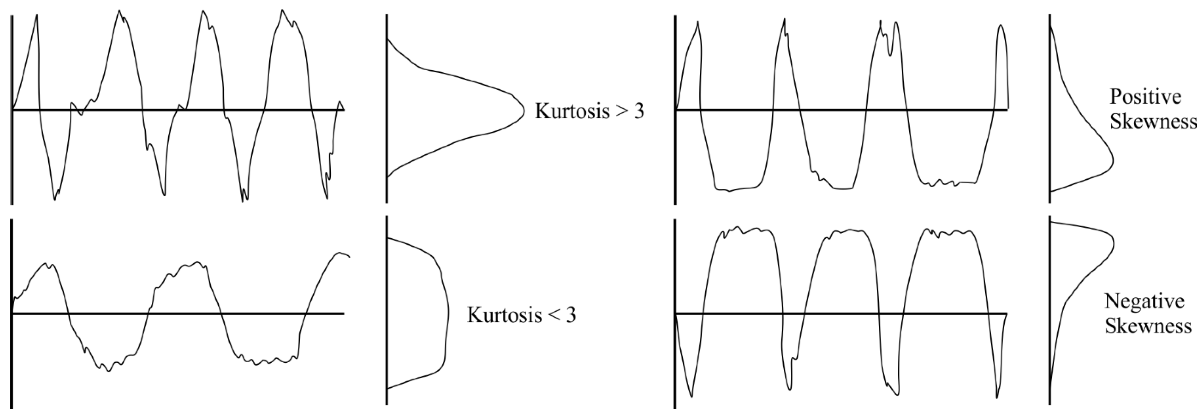
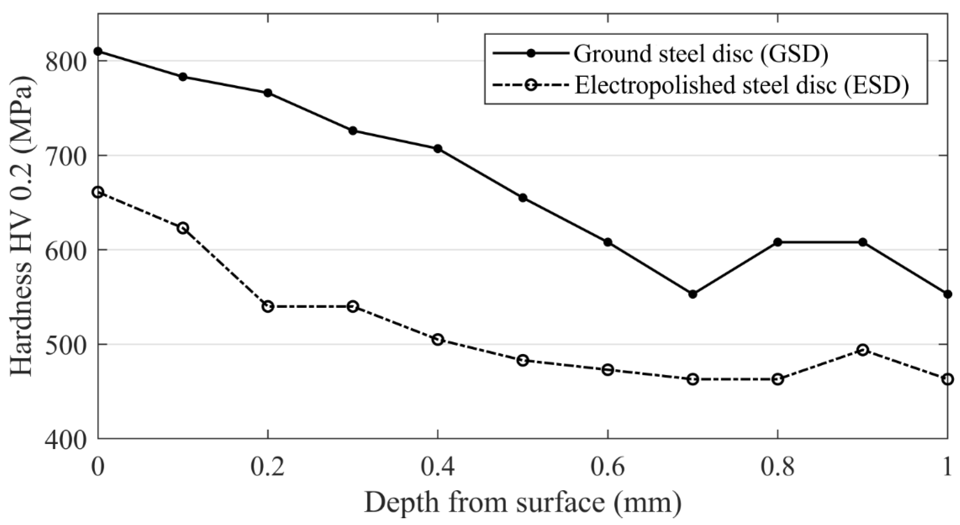
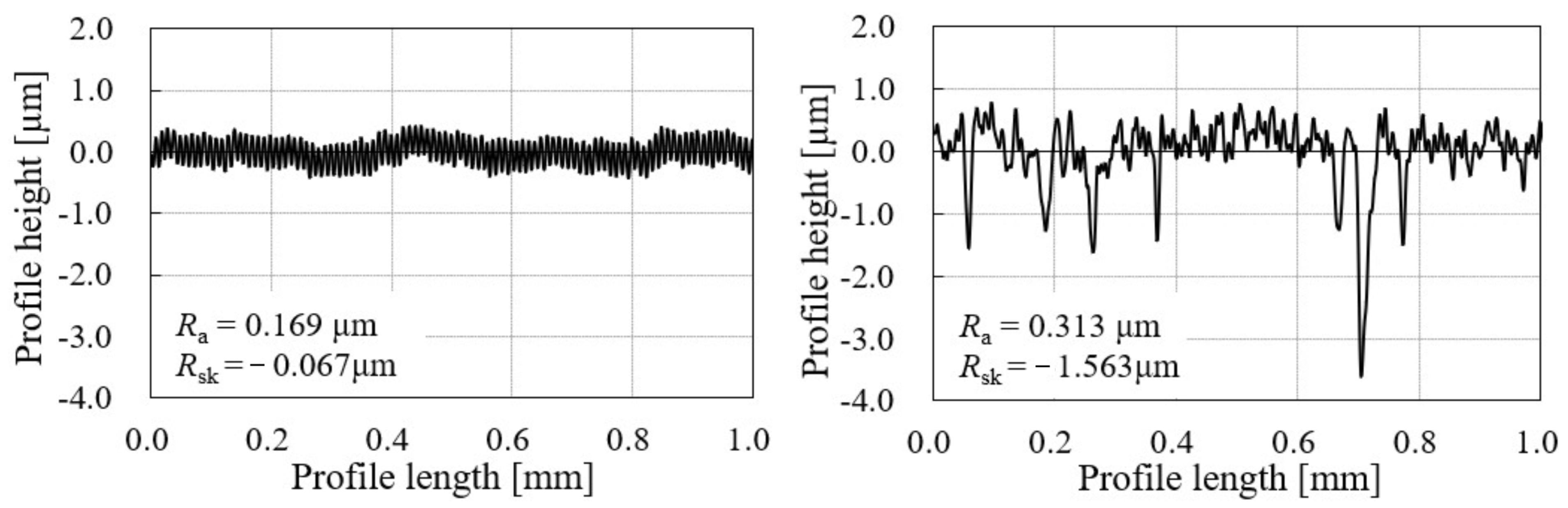
2.4. Impact of Electropolishing on Surface Profile, Topography, and Hardness

The electropolishing process aims to produce a surface with high Rku and negative Rsk values without increasing the average surface roughness Ra. The significant increase in Ra would consequently lead to higher friction and wear. The initial surface roughness of steel discs was Ra = 0.2 µm. Generally, the higher the current density and/or longer the electropolishing time, the larger the reduction in surface hardness and change in geometry that can be expected. As presented in Table 3, the current density of 15 A/dm2 produced an unacceptable surface with a high Ra value and a Rsk value near zero. Current densities of 25 A/dm2 and 30 A/dm2 produced acceptable surfaces characterized by a small increase in surface roughness Ra with high Rku and negative Rsk values. Higher values of current density (40 A/dm2 and 50 A/dm2) produced surfaces with significantly higher Ra values. After different combinations were tested, the current density of 30 A/dm2 and electropolishing time of 5 min were adopted, considering the produced surface topography and possible impact on surface hardness and geometry. The hardness profile of steel discs is given in Figure 4. Surface hardness HV 0.2 for ground and electropolished steel discs corresponded to 810 HV and 661 HV, respectively, indicating an 18% reduced surface hardness of electropolished steel. Surface hardness reduction occurs due to the removal of a thin hardened layer from the disc surface during electropolishing.
Surface profile measurements were performed using a Mitutoyo SJ-500 measuring instrument according to ISO 4287 [30]. Examples of the surface profiles of ground and electropolished steel discs are presented in Figure 5. The surface profile of ground steel exhibited a uniform shape with a lower Ra value and a Rsk value near zero. On the other hand, the surface profile of the electropolished steel had stochastically distributed pits. The pits vary in diameter from approximately 10 μm to 20 μm, while their depth ranges from 1 μm to 4 μm. Due to induced pits, the electropolished steel disc had a higher Ra value and a significantly more negative Rsk value than the ground surface. It should be noted that a higher Ra value was primarily a consequence of induced pits. For example, the Ra value for the electropolished steel disc surface profile from 0.4 mm to 0.6 mm (i.e., between two pits, Figure 5b) equals Ra = 0.194 μm, similar to the ground surface value.
Scanning electron microscope (SEM) images of steel disc surfaces are presented in Figure 6. The ground steel surface was characterized by grinding marks, Figure 6a, while the electropolished surface was characterized by pits of irregular shapes and various sizes, Figure 6b. The distribution of the pits on the electropolished surface was uneven, meaning there were regions on the surface with sparser and denser pit distributions. Using commercially available image processing software, the pit distribution was calculated. In the regions with sparser pit distribution, the pit area density was 5% of the total area. In denser regions, that value rises to 12%. On average, the calculated pit area density was 10%. Area density in the range of 5–20% was reported as beneficial in terms of friction reduction [31,32,33]. Several potential explanations for pitting formation can be found in existing research. Under higher current densities, pitting occurs due to oxygen bubbles evolving from the surface (i.e., gas evolution). Consequently, the phenomenon referred to as Broken Bubble Tunnelling Effect (BBTE) takes place. A broken bubble represents a place with a higher current density, increasing the dissolution rate and consequently generating a pitting hole [34]. Pits during electropolishing are internally polished and therefore superimposed on the polishing process and do not displace it [35]. Apart from the gas evolution, Imboden and Sibley [36] argued that pits also occur near surface inclusions and that mild agitation of the solution considerably reduces pitting. Lastly, phenomenon such as streaking due to hydrogen gas evolution can also contribute to uneven pit distribution as it affects the roughness at smaller frequencies [37].

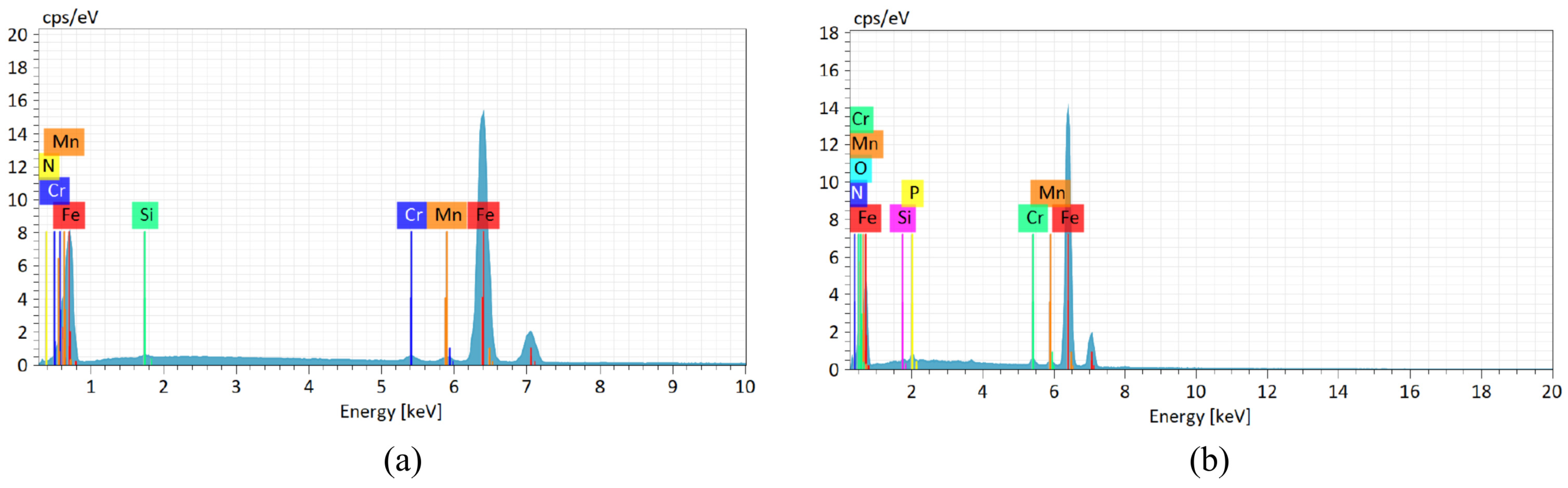
2.5. Chemical Composition of Steel Surfaces

The chemical composition of the ground and electropolished steel surfaces was investigated by Energy Dispersive Spectroscopy (EDS), and the results are presented in Figure 7. Summarized results are presented in Table 4.
Electropolishing passivates the workpiece due to the formation of the oxide surface film, which was observed by a high percentage of oxygen in the electropolished steel surface. In addition, phosphorus can be found on the electropolished surface. The generated phosphate layer acts as secondary passivation when mild steel electropolishing is conducted in phosphoric and sulfuric acid [38]. The generation of phosphate films on the steel surfaces was also reported in [12,39]. Oxide and phosphate surface films, as well as surface pits produced by electropolishing, contributed to the darker appearance of the electropolished steel disc (Figure 8).

2.6. Variable Selection

In the presented experimental setup, the steel disc and the bronze specimen produce initial line contact, and the corresponding dimensionless film thickness parameter Hmin was calculated according to [40].
H m i n = 2.65 · U 0.70 · G 0.54 · W 0.13
A detailed description of the Equation (3) can be found in [40,41,42] and in the nomenclature section at the end of the manuscript. The values of parameter Hmin ranged from 5.2 × 10⁻⁶ in the boundary lubrication regime up to 2.5 × 10⁻⁵ in the mixed lubrication regime. Some important parameters used in the calculation of the parameter Hmin are given Table 5.
The oil film thickness parameter λ is often used to classify lubrication regimes. It is defined as the ratio of the minimum oil film thickness to the composite surface roughness [42].
λ = h m i n R q 1 2 + R q 2 2
where λ < 1 indicates boundary lubrication, 1 < λ < 3 represents mixed lubrication, and λ > 3 indicates hydrodynamic lubrication [43], hmin is the minimum film thickness, while Rq1 and Rq2 represent the root mean square roughness of the bronze specimen and the steel disc, respectively. The change in the value of λ ratio was achieved by varying the sliding speed (i.e., the rotational speed of a steel disc) and the initial surface roughness of steel discs and bronze specimens. Steel discs were ground or ground and additionally electropolished. Bronze specimens were milled or ground, as these machining processes are commonly used for bronze worm wheel manufacturing. Additionally, the milled surface has increased composite surface roughness compared to the ground surface, resulting in a lower λ ratio, thus establishing a boundary lubrication regime. Average surface profile values for steel discs and bronze specimens are provided in Table 6.
The normal load of 500 N, resulting in an initial Hertzian pressure of 292 MPa, was applied in all tests. The load was chosen as a possible design working point regarding the pitting resistance for CuSn12 at 425 MPa [22]. Test setups in this work are displayed in Table 7. Each test was repeated three times to ensure the reproducibility of the results. The tests were conducted for six hours (t = 21,600 s). By conducting the tests for a longer period, it was possible to investigate the duration of the running-in phase for different experimental setups and the coefficient of friction at the start of the test, during the running-in phase, and in a steady-state operation. In Table 7, “G,” “M,” and “E” stand for “ground,” “milled,” and “electropolished,” respectively, while “SD” and “BS” stand for “steel disc” and “bronze specimen,” respectively. Three test setup comparisons were performed according to the last column in Table 7: 1 vs. 2, 3 vs. 4, and 5 vs. 6.

3. Results and Discussion

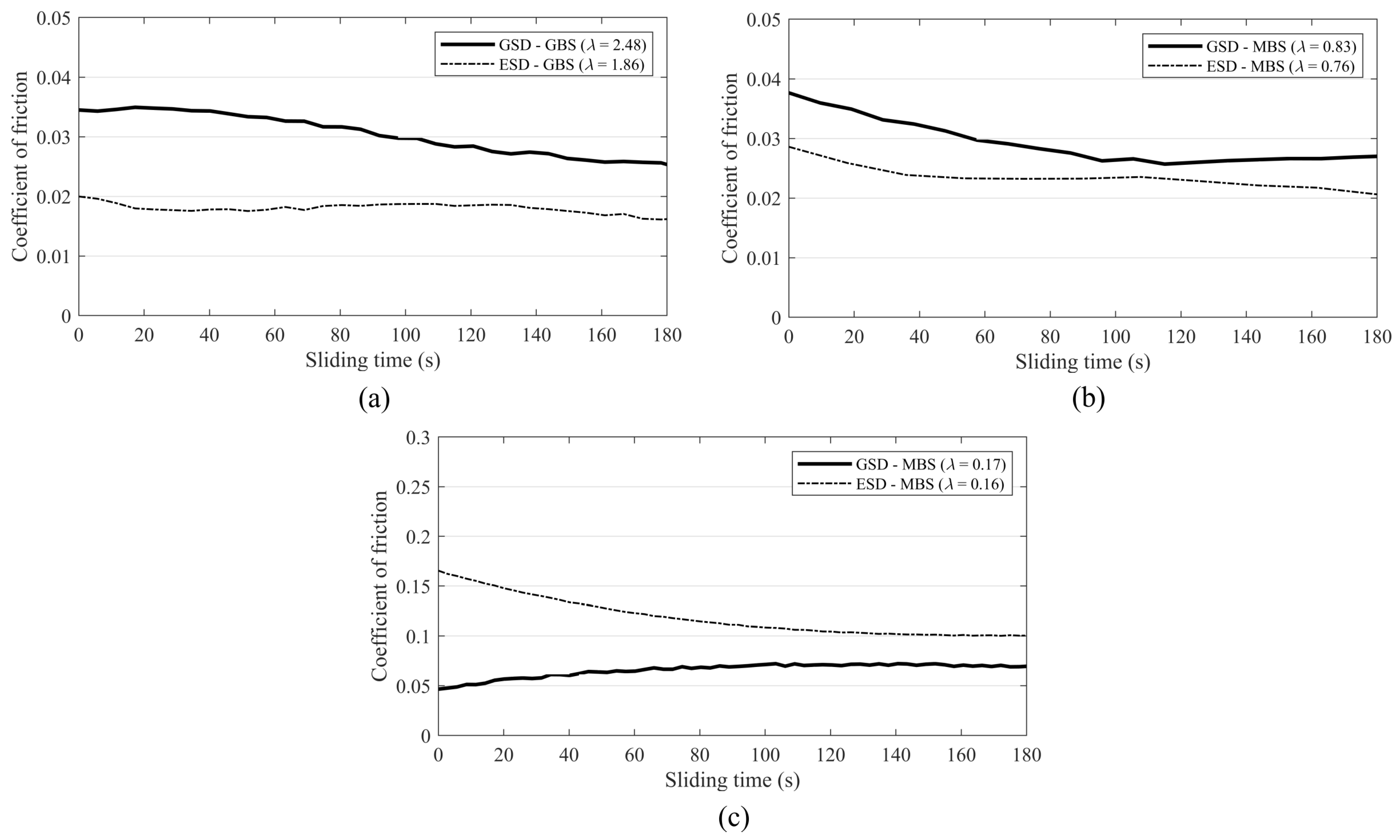
3.1. Sliding Test Results

A rotating steel disc with an outer diameter ddisc = 60 mm and a static bronze specimen with a thickness b = 5 mm were used to produce initial line contact in sliding tests. A detailed and schematic description of specimens is given in Section 2.2. Test results are reported for two sliding periods: the first three minutes of the test (t = 180 s) and the total sliding time (t = 21,600 s). For sliding time t = 180 s, initial non-conformal line contact can be assumed with no change in contact geometry, i.e., no significant bronze wear occurred. Also, λ ratios given in Table 7 are applicable. In the mixed lubrication regime and upper range of the boundary lubrication regime, the ESD-GBS pair performs with a considerably lower coefficient of friction than the GSD-GBS pair. Results with the ground bronze specimen (GBS) are presented in Figure 9a, while results with the milled bronze specimen (MBS) are presented in Figure 9b. However, in the lower range of the boundary lubrication regime, the coefficient of friction for the ESD-MBS pair was significantly higher compared to the GSD-MBS pair (Figure 9c). A comparison of average coefficients of friction for non-conformal line contact is given in Figure 10. Electropolished surfaces resulted in a significant reduction in friction in the mixed lubrication regime and the upper range of the boundary lubrication regime. ESD-GBS and ESD-MBS pairs had a 30% and 25% lower coefficient of friction compared to GSD pairs, respectively. Although the change in surface topography of electropolished steel resulted in higher surface roughness and lower λ ratios, the induced surface pits provided a friction reduction effect. This can be attributed to surface pits acting as micro-oil reservoirs and providing the functionality of micro-bearings. Consequently, a local increase in the oil film thickness occurs, which results in a lower coefficient of friction [3,44,45]. However, in the lower range of the boundary lubrication regime, the ESD-MBS pair had a 50% higher coefficient of friction compared to the GSD-MBS pair. The load in the boundary lubrication regime is greatly supported by contacting surfaces. If surfaces in contact are rougher, an increase in the coefficient of friction is expected. Surface pits induced through electropolishing consequentially increase surface roughness, as shown by higher Ra and Rq values (Table 6). Additionally, there is an increase in contact stresses on surface pit edges. If additional lubricant from pits cannot compensate for an increase in roughness and edge stresses, the coefficient of friction will increase [46].
Sliding test results for a total sliding time of 21,600 s are given in Figure 11. In sliding tests that started with a mixed lubrication regime and an upper range of boundary lubrication regimes, the coefficient of friction for ESD pairs was lower compared to GSD pairs (Figure 11a). Additionally, ESD pairs showed a faster transition to steady-state friction, particularly the ESD—MBS pair (Figure 11b). The transition to steady-state friction is caused by bronze specimen wear, resulting in a contact geometry change. At the start of the test, steel discs and bronze specimens produce line contact that gradually changes to rectangular contact patches due to bronze wear (Figure 12). In other words, contact geometry transforms from non-conformal line contact to conformal cylinder-inner cylinder contact. A change in contact geometry resulted in a lubrication regime shift from boundary or mixed to hydrodynamic, which can also be observed by the lower coefficient of friction.
The contact patch area on the bronze specimen was measured after the sliding test was completed. The results are presented in Figure 13. Bronze wear occurred at the start of the tests and during the running-in phase. The running-in phase is characterized by a gradually decreasing coefficient of friction as the contact area enlarges. It lasted until a steady state was established, characterized by a low and constant coefficient of friction. Such low values indicate a hydrodynamic lubrication regime where the fluid film fully supports contacting surfaces and no further bronze wear occurs. A larger contact patch area indicates that ESD produced more bronze wear in a mixed lubrication regime. The difference in contact patch area can be attributed to a noticeable difference in starting λ ratios. Due to the higher Ra and Rq parameters of the ESD surface, the λ ratio for the ESD-GBS pair (λ = 1.86) is considerably lower compared to the GSD-GBS pair (λ = 2.48), indicating a more severe mixed lubrication regime for the ESD-GBS pair. However, when the difference in starting λ ratios is smaller, i.e., GSD-MBS (λ = 0.83) and ESD-MBS (λ = 0.76), the difference in bronze wear is also smaller. In the tests that started from the boundary lubrication regime at λ = 0.16–0.17, bronze wear was similar for both ESD and GSD pairs, as there is practically no difference in their λ ratios. The presented data show that rougher discs, in this case, ESD, produce more wear. Similar findings on dimpled discs have been reported by Kovalchenko et al. [32]. Furthermore, wear results suggest faster running-in for ESD pairs in a mixed and upper range of boundary lubrication regimes. In practice, this may benefit components that depend on proper and efficient running-in, such as worm pairs.
Some of the limitations and drawbacks of the presented experimental research should be addressed to possibly improve further studies. Sliding tests were conducted under a pure sliding regime, while in reality many non-conformal contacts operate in rolling-sliding conditions. With the current disc-specimen configuration, the goal was to evaluate the initial line contact condition as well as the transition towards hydrodynamic lubrication due to bronze wear. A reverse configuration, i.e., bronze disc-steel specimen, would result in constant line contact, and the durability of the electropolished steel surface could be better assessed.

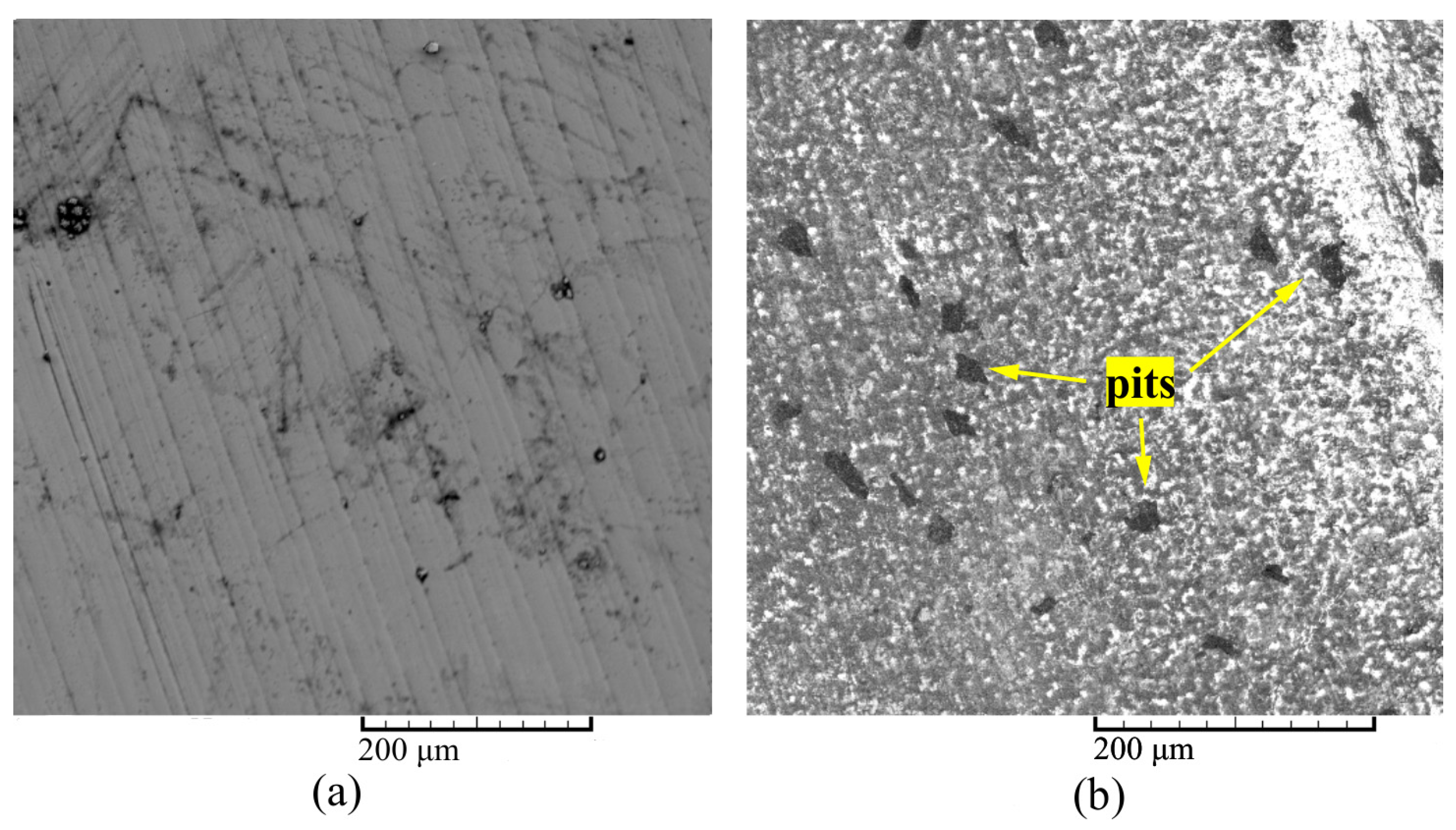
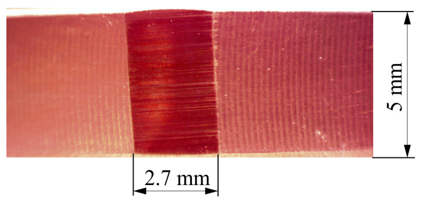
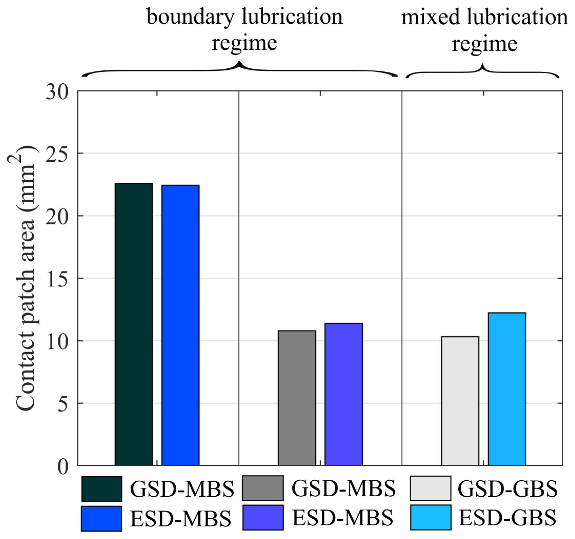
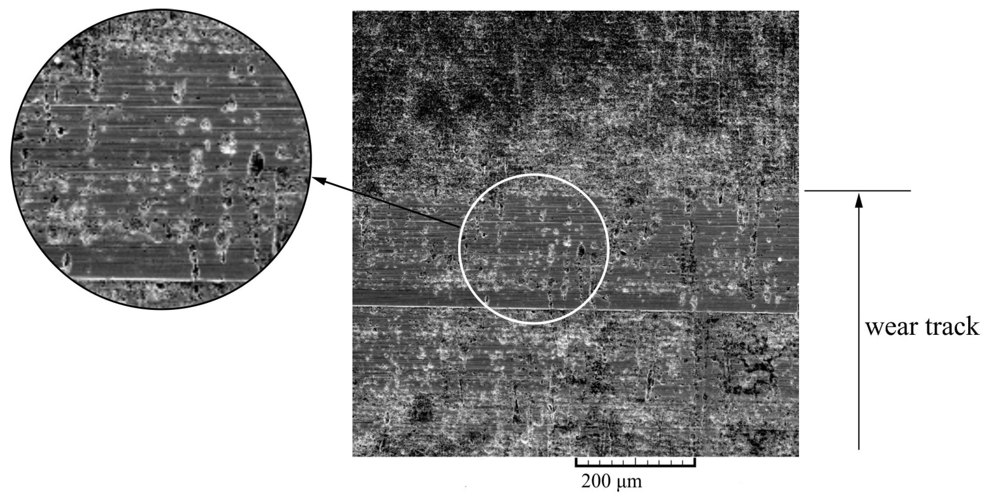
3.2. Surface Inspection after the Sliding Tests

After the sliding test, the electropolished steel surface was examined by SEM and ESD. The state of the ESD surface after the test is presented in Figure 14. EDS analyses were conducted on the marked places on the SEM micrographs shown in Figure 15: wear track (Spectrum 1) and base electropolished steel surface (Spectrum 2). The results in Table 8 point to a reduction in oxygen and phosphorus in the wear track due to the partial removal of the oxide and phosphate layers from the surface. The surface profile of ESD after the test is presented in Figure 16. Since no changes in Ra or Rsk values were detected and pits remained on the electropolished surface after the test, it can be concluded that no visible wear of the base material occurred despite the reduced surface hardness of electropolished steel.
Besides changes in surface topography, another contributing factor in the tribological behavior of electropolished steel was the oxide surface layer formed during electropolishing. Studies showed that black oxide surfaces yield a lower coefficient of friction than ground steel surfaces in lubricated rolling/sliding contacts and improve adhesive wear resistance [47]. In addition, the electropolished surface had a lower hardness (Figure 4) and enabled faster running-in, as observed from the results in Figure 11. Optimized running-in was also reported by Ueda et al. in micro-pitting tests when black oxide coating was applied to steel surfaces [48]. Another chemical element in the surface layer of electropolished steel was phosphorus, indicating phosphates derived from phosphoric acid (H3PO4). Although its content is relatively small compared to oxygen (0.65 vs. 10.11 wt.%), phosphorus is commonly used in various friction reduction additives and coatings [49,50], and its presence could also have contributed to the friction reduction observed in this research. As the results suggest, the oxide surface layer experienced significant wear during the running-in phase and, as such, fulfilled the function of coating only for a shorter period, as opposed to conventional coatings, which are more durable. Another drawback of the presented surface modification is the use of strong acids, which require proper handling and disposal due to possible negative environmental effects.

3.3. Stribeck Curve for Non-Conformal Contact

Approximated Stribeck curves for ground and electropolished steel-bronze pairs based on the coefficient of friction results for non-conformal line contact (Figure 10) are presented in Figure 17. The benefits of the electropolished surface first become evident in the boundary mixed lubrication regime defined by λ ≈ 0.5. In the mixed lubrication regime (1 < λ < 3), the coefficient of friction reduction becomes less significant as λ ratio increases. For the same sliding test conditions, ESD pairs operate in lubrication regimes defined by lower λ ratios due to surface topography and roughness changes. The electropolished surface lowered λ ratio from 2.48 to 1.86 and from 0.83 to 0.76. However, such lubrication regimes defined by lower λ ratios exhibit the most friction reduction compared to GSD pairs (Figure 11). Unlike in conformal contacts, where more successful use cases of textured surfaces have been reported [3], in non-conformal contacts, surface textures may produce both positive and negative effects. By comparing Stribeck curves for untextured and textured surfaces in non-conformal contact, Gu et al. [51] showed positive effects of surface texturing in mixed and hydrodynamic lubrication regimes. In contrast, negative effects on tribological performance occurred in the boundary lubrication regime.
As presented by the Stribeck curve in this study, positive effects should be expected for λ > 0.5, while for lower λ values, the coefficient of friction increases. These observations suggest that surface pits provide additional lubrication, which helps to reduce asperity contact for λ > 0.5, while increased surface roughness of electropolished surfaces results in increased friction in the lower range of the boundary lubrication regime for λ < 0.5, where the load is completely supported by the surface asperity-asperity contacts. To conclude, electropolishing proved to be a successful surface modification approach for non-conformal contacts in both boundary and mixed lubrication regimes. It could provide an alternative to common surface texturing techniques, such as LST, especially for complex geometries that usually operate in boundary and mixed lubrication regimes.

4. Conclusions

The tribological performance of the electropolished steel (16MnCr5)–bronze (CuSn12) pair was investigated by measuring the coefficient of friction and bronze wear in sliding tests. The results were compared to ground steel surfaces in the boundary and mixed lubrication regimes. The following conclusions can be drawn:
  • Electropolishing modifies the steel surface in two ways: by creating surface texture through surface pits and dimples and by generating a surface coating in the form of an oxide surface layer.
  • The main advantage of electropolished steel is a lower coefficient of friction, up to 30%, in a mixed lubrication regime and an upper range of boundary lubrication regimes. According to the Stribeck curve, friction reduction should be expected for λ > 0.5, while in lubrication regimes defined by λ < 0.5, the coefficient of friction increases.
  • Electropolishing enables faster running-in through an oxide surface layer on a steel surface. Faster running-in could benefit machine components that depend on proper and efficient running-in, such as worm pairs.
  • The presented findings suggest electropolishing as an alternative method for surface texturing, as it is a cost- and time-effective method applicable to complex geometries.
The limitations of the presented work should be addressed. Even though electropolishing may be applied to complex geometries, the density and geometry of the pits produced cannot be precisely controlled as in other surface texturing methods. In addition, since electropolishing parameters were empirically selected, they do not represent an optimal solution for the surface texturing of carburized steel. Further research should be conducted to define parameters for achieving different pit sizes and area densities. In future studies, electropolishing will be employed in worm pairs on carburized steel worms to increase the overall efficiency of such a gearing system through an improved running-in process and friction reduction.

Author Contributions

Conceptualization, R.M., D.M. and D.Ž.; methodology, R.M., D.M., I.Č. and D.Ž.; validation, R.M. and D.Ž.; formal analysis, R.M.; investigation, R.M., S.J. and D.Ž.; resources, S.J., M.Š. and D.Ž.; data curation, R.M.; writing—original draft preparation, R.M. and D.Ž.; writing—review and editing, R.M., I.Č., S.J., M.Š. and D.Ž.; visualization, R.M. and S.J.; supervision, D.Ž. All authors have read and agreed to the published version of the manuscript.

Funding

This research received no external funding.

Data Availability Statement

The data presented in this study are available on request from the corresponding author.

Acknowledgments

This work has been supported by Metal Centre Čakovec under project KK.01.1.1.02.0023. Also, the authors would like to thank DMB product d.o.o. for their help and assistance with specimen preparation.

Conflicts of Interest

The authors declare no conflict of interest.

Nomenclature/Abbreviations

E   1 E = 1 2 1 υ 1 2 E 1 + 1 υ 2 2 E 2 reduced Young’s modulus [MPa]
ESD-electropolished steel disc
G   G = α E dimensionless materials parameter [-]
GBS-ground bronze specimen
GSD-ground steel disc
Hmin-dimensionless film thickness parameter [-]
hmin   h m i n = H m i n · R minimum film thickness [m]
MBS-milled bronze specimen
R   1 R = 1 R 1 + 1 R 2 reduced radius of curvature [m]
Ra-average surface roughness [µm]
Rk-core roughness depth [µm]
Rku-Kurtosis [-]
Rpk-reduced peak height [µm]
Rq-root mean square roughness [µm]
Rsk-Skewness [-]
Rvk-reduced valley height [µm]
U   U = η · u E · R dimensionless speed parameter [-]
u   u = u 1 + u 2 2 entraining surface velocity [-]
W   W = w E · R dimensionless load parameter [-]
w-load per unit length [N/m]
α-pressure-viscosity coefficient [m2/N]
η-viscosity at atmospheric pressure and temperature
λ-ratio of the minimum oil film thickness to the composite surface roughness

References

  1. Kovalchenko, A.; Ajayi, O.; Erdemir, A.; Fenske, G.; Etsion, I. The Effect of Laser Texturing of Steel Surfaces and Speed-Load Parameters on the Transition of Lubrication Regime from Boundary to Hydrodynamic. Tribol. Trans. 2004, 47, 299–307. [Google Scholar] [CrossRef]
  2. Schneider, J.; Braun, D.; Greiner, C. Laser Textured Surfaces for Mixed Lubrication: Influence of Aspect Ratio, Textured Area and Dimple Arrangement. Lubricants 2017, 5, 32. [Google Scholar] [CrossRef] [Green Version]
  3. Gachot, C.; Rosenkranz, A.; Hsu, S.M.; Costa, H.L. A Critical Assessment of Surface Texturing for Friction and Wear Improvement. Wear 2017, 372–373, 21–41. [Google Scholar] [CrossRef]
  4. Ali, S.; Kurniawan, R.; Moran, X.; Ahmed, F.; Danish, M.; Aslantas, K. Effect of Micro-Dimple Geometry on the Tribological Characteristics of Textured Surfaces. Lubricants 2022, 10, 328. [Google Scholar] [CrossRef]
  5. Vrbka, M.; Šamánek, O.; Šperka, P.; Návrat, T.; Křupka, I.; Hartl, M. Effect of Surface Texturing on Rolling Contact Fatigue within Mixed Lubricated Non-Conformal Rolling/Sliding Contacts. Tribol. Int. 2010, 43, 1457–1465. [Google Scholar] [CrossRef]
  6. Vrbka, M.; Křupka, I.; Šamánek, O.; Svoboda, P.; Vaverka, M.; Hartl, M. Effect of Surface Texturing on Lubrication Film Formation and Rolling Contact Fatigue within Mixed Lubricated Non-Conformal Contacts. Meccanica 2011, 46, 491–498. [Google Scholar] [CrossRef]
  7. Galda, L.; Pawlus, P.; Sep, J. Dimples Shape and Distribution Effect on Characteristics of Stribeck Curve. Tribol. Int. 2009, 42, 1505–1512. [Google Scholar] [CrossRef]
  8. Gupta, N.; Tandon, N.; Pandey, R.K. An Exploration of the Performance Behaviors of Lubricated Textured and Conventional Spur Gearsets. Tribol. Int. 2018, 128, 376–385. [Google Scholar] [CrossRef]
  9. Gupta, N.; Tandon, N.; Pandey, R.K.; Vidyasagar, K.E.C.; Kalyanasundaram, D. Tribological and Vibration Studies of Textured Spur Gear Pairs under Fully Flooded and Starved Lubrication Conditions. Tribol. Trans. 2020, 63, 1103–1120. [Google Scholar] [CrossRef]
  10. Li, W.; Lu, L.; Zeng, D. The Contribution of Topography Formed by Fine Particle Peening Process in Reducing Friction Coefficient of Gear Steel. Tribol. Trans. 2020, 63, 9–19. [Google Scholar] [CrossRef]
  11. Nakatsuji, T.; Mori, A.; Shimotsuma, Y. Pitting Durability of Electrolytically Polished Medium Carbon Steel Gears. Tribol. Trans. 1995, 38, 223–232. [Google Scholar] [CrossRef]
  12. Nakatsuji, T.; Mori, A. Pitting Durability of Electrolytically Polished Medium Carbon Steel Gears—Succeeding Report. Tribol. Trans. 1999, 42, 393–400. [Google Scholar] [CrossRef]
  13. Gadelmawla, E.S.; Koura, M.M.; Maksoud, T.M.A.; Elewa, I.M.; Soliman, H.H. Roughness Parameters. J. Mater. Process. Technol. 2002, 123, 133–145. [Google Scholar] [CrossRef]
  14. Akamatsu, Y.; Tsushima, N.; Goto, T.; Hibi, K. Influence of Surface Roughness Skewness on Rolling Contact Fatigue Life. Tribol. Trans. 1992, 35, 745–750. [Google Scholar] [CrossRef]
  15. Sedlaček, M.; Gregorčič, P.; Podgornik, B. Use of the Roughness Parameters S Sk and S Ku to Control Friction—A Method for Designing Surface Texturing. Tribol. Trans. 2017, 60, 260–266. [Google Scholar] [CrossRef]
  16. Křupka, I.; Koutný, D.; Hartl, M. Behavior of Real Roughness Features within Mixed Lubricated Non-Conformal Contacts. Tribol. Int. 2008, 41, 1153–1160. [Google Scholar] [CrossRef]
  17. Dzierwa, A. Influence of Surface Preparation on Surface Topography and Tribological Behaviours. Arch. Civ. Mech. Eng. 2017, 17, 502–510. [Google Scholar] [CrossRef]
  18. Senatore, A.; Risitano, G.; Scappaticci, L.; D’Andrea, D. Investigation of the Tribological Properties of Different Textured Lead Bronze Coatings under Severe Load Conditions. Lubricants 2021, 9, 34. [Google Scholar] [CrossRef]
  19. Lu, X.; Khonsari, M.M. An Experimental Investigation of Dimple Effect on the Stribeck Curve of Journal Bearings. Tribol. Lett. 2007, 27, 169. [Google Scholar] [CrossRef]
  20. Wang, Y.; Jacobs, G.; König, F.; Zhang, S.; von Goeldel, S. Investigation of Microflow Effects in Textures on Hydrodynamic Performance of Journal Bearings Using CFD Simulations. Lubricants 2023, 11, 20. [Google Scholar] [CrossRef]
  21. Rosenkranz, A.; Grützmacher, P.G.; Gachot, C.; Costa, H.L. Surface Texturing in Machine Elements − A Critical Discussion for Rolling and Sliding Contacts. Adv. Eng. Mater. 2019, 21, 1900194. [Google Scholar] [CrossRef]
  22. ISO ISO/TR 14521.2; Gear—Calculation of Load Capacity of Wormgears. International Organization for Standardization: Geneva, Switzerland, 2006.
  23. Miler, D.; Hoić, M.; Domitran, Z.; Žeželj, D. Prediction of Friction Coefficient in Dry-Lubricated Polyoxymethylene Spur Gear Pairs. Mech. Mach. Theory 2019, 138, 205–222. [Google Scholar] [CrossRef]
  24. Hoar, T.P.; Mowat, J.A.S. Mechanism of Electropolishing. Nature 1950, 165, 64–65. [Google Scholar] [CrossRef]
  25. Landolt, D. Fundamental Aspects of Electropolishing. Electrochim. Acta 1987, 32, 1–11. [Google Scholar] [CrossRef]
  26. Yang, G.; Wang, B.; Tawfiq, K.; Wei, H.; Zhou, S.; Chen, G. Electropolishing of Surfaces: Theory and Applications. Surf. Eng. 2017, 33, 149–166. [Google Scholar] [CrossRef]
  27. Han, W.; Fang, F. Fundamental Aspects and Recent Developments in Electropolishing. Int. J. Mach. Tools Manuf. 2019, 139, 1–23. [Google Scholar] [CrossRef]
  28. Rangaswamy, P.; Scherer, C.P.; Bourke, M.A.M. Experimental Measurements and Numerical Simulation of Stress and Microstructure in Carburized 5120 Steel Disks. Mater. Sci. Eng. A 2001, 298, 158–165. [Google Scholar] [CrossRef]
  29. ASTM-E1558; Standard Guide for Electrolytic Polishing of Metallographic Specimens. The American Society for Testing and Materials: West Conshohocken, PA, USA, 1999.
  30. ISO 4287:1997; Geometrical Product Specifications (GPS)—Surface Texture: Profile Method—Terms, Definitions and Surface Texture Parameters. International Organization for Standardization: Geneva, Switzerland, 1997.
  31. Ronen, A.; Etsion, I.; Kligerman, Y. Friction-Reducing Surface-Texturing in Reciprocating Automotive Components. Tribol. Trans. 2001, 44, 359–366. [Google Scholar] [CrossRef]
  32. Kovalchenko, A.; Ajayi, O.; Erdemir, A.; Fenske, G. Friction and Wear Behavior of Laser Textured Surface under Lubricated Initial Point Contact. Wear 2011, 271, 1719–1725. [Google Scholar] [CrossRef]
  33. Ghaei, A.; Khosravi, M.; Badrossamay, M.; Ghadbeigi, H. Micro-Dimple Rolling Operation of Metallic Surfaces. Int. J. Adv. Manuf. Technol. 2017, 93, 3749–3758. [Google Scholar] [CrossRef]
  34. Lee, S.J.; Chen, Y.H.; Hung, J.C. The Investigation of Surface Morphology Forming Mechanisms in Electropolishing Process. Int. J. Electrochem. Sci. 2012, 7, 12495–12506. [Google Scholar] [CrossRef]
  35. Neufeld, P.; Southall, D. Gas Evolution and Pitting in Electropolishing. Trans. IMF 1976, 54, 40–44. [Google Scholar] [CrossRef]
  36. Imboden, R.L.; Sibley, R.S. Anodic Polishing of Plain Carbon Steels. Trans. Electrochem. Soc. 1942, 82, 227. [Google Scholar] [CrossRef]
  37. Pendyala, P.; Bobji, M.S.; Madras, G. Evolution of Surface Roughness During Electropolishing. Tribol. Lett. 2014, 55, 93–101. [Google Scholar] [CrossRef]
  38. Gabe, D.R. Electropolishing of Mild Steel in Phosphoric and Perchloric Acid Containing Electrolytes. Corros. Sci. 1973, 13, 175–185. [Google Scholar] [CrossRef]
  39. Nakatsuji, T.; Mori, A. Tribological Properties of Eiectrolytically Polished Surfaces of Carbon Steel. Tribol. Trans. 1998, 41, 179–188. [Google Scholar] [CrossRef]
  40. Dowson, D. Paper 10: Elastohydrodynamics. Proc. Inst. Mech. Eng. Conf. Proc. 1967, 182, 151–167. [Google Scholar] [CrossRef]
  41. Dowson, D.; Higginson, G.R. Elasto-Hydrodynamic Lubrication, 2nd ed.; Pergamon Press: Oxford, UK, 1977; ISBN 0-08-021303-0. [Google Scholar]
  42. Stachowiak, G.W.; Batchelor, A.W. Engineering Tribology; Elsevier: Amsterdam, The Netherlands, 2014; ISBN 9780123970473. [Google Scholar]
  43. Hutchings, I.; Shipway, P. Tribology—Friction and Wear of Engineering Materials, 2nd ed.; Elsevier: Amsterdam, The Netherlands, 2017; ISBN 978-0-08-100910-9. [Google Scholar]
  44. Sedlaček, M.; Podgornik, B.; Vižintin, J. Planning Surface Texturing for Reduced Friction in Lubricated Sliding Using Surface Roughness Parameters Skewness and Kurtosis. Proc. Inst. Mech. Eng. Part J. Eng. Tribol. 2012, 226, 661–667. [Google Scholar] [CrossRef]
  45. Ren, N.; Nanbu, T.; Yasuda, Y.; Zhu, D.; Wang, Q. Micro Textures in Concentrated-Conformal-Contact Lubrication: Effect of Distribution Patterns. Tribol. Lett. 2007, 28, 275–285. [Google Scholar] [CrossRef]
  46. Costa, H.L.; Hutchings, I.M. Effects of Die Surface Patterning on Lubrication in Strip Drawing. J. Mater. Process. Technol. 2009, 209, 1175–1180. [Google Scholar] [CrossRef]
  47. Hager, C.H.; Evans, R.D. Friction and Wear Properties of Black Oxide Surfaces in Rolling/Sliding Contacts. Wear 2015, 338–339, 221–231. [Google Scholar] [CrossRef]
  48. Ueda, M.; Spikes, H.; Kadiric, A. Influence of Black Oxide Coating on Micropitting and ZDDP Tribofilm Formation. Tribol. Trans. 2022, 65, 242–259. [Google Scholar] [CrossRef]
  49. Zhu, L.; Wu, X.; Zhao, G.; Wang, X. Tribological Characteristics of Bisphenol AF Bis(Diphenyl Phosphate) as an Antiwear Additive in Polyalkylene Glycol and Polyurea Grease for Significantly Improved Lubrication. Appl. Surf. Sci. 2016, 363, 145–153. [Google Scholar] [CrossRef]
  50. Liu, C.; Chen, L.; Zhou, J.; Zhou, H.; Chen, J. Tribological Properties of Adaptive Phosphate Composite Coatings with Addition of Silver and Molybdenum Disulfide. Appl. Surf. Sci. 2014, 300, 111–116. [Google Scholar] [CrossRef]
  51. Gu, C.; Meng, X.; Xie, Y.; Zhang, D. The Influence of Surface Texturing on the Transition of the Lubrication Regimes between a Piston Ring and a Cylinder Liner. Int. J. Engine Res. 2017, 18, 785–796. [Google Scholar] [CrossRef]
Figure 1. Schematic representation of kurtosis (Rku) and skewness (Rsk).
Lubricants 11 00325 g001
Figure 2. Experimental rig.
Lubricants 11 00325 g002
Figure 3. Electropolishing setup.
Lubricants 11 00325 g003
Figure 4. Hardness profile of steel discs.
Lubricants 11 00325 g004
Figure 5. Initial surface roughness of (a) a ground steel disc and (b) an electropolished steel disc.
Lubricants 11 00325 g005
Figure 6. SEM image of (a) a ground steel disc surface and (b) an electropolished steel disc surface.
Lubricants 11 00325 g006
Figure 7. EDS spectrum of (a) a ground steel disc and (b) an electropolished steel disc.
Lubricants 11 00325 g007
Figure 8. Electropolished steel disc (ESD) and ground steel disc (GSD).
Lubricants 11 00325 g008
Figure 9. Results of the sliding test (t = 180 s): (a) the ground bronze specimen in the mixed lubrication regime; (b) the milled bronze specimen in the boundary lubrication regime; (c) the milled bronze specimen in the boundary lubrication regime.
Lubricants 11 00325 g009
Figure 10. Comparison of the average coefficient of friction for non-conformal contact (t = 180 s).
Lubricants 11 00325 g010
Figure 11. Results of the sliding test (t = 21,600 s): (a) the ground bronze specimen in the mixed lubrication regime; (b) the milled bronze specimen in the boundary lubrication regime; (c) the milled bronze specimen in the boundary lubrication regime.
Lubricants 11 00325 g011
Figure 12. Contact patch on the bronze specimen after the ESD-GBS test (v = 3 m/s, t = 21,600 s).
Lubricants 11 00325 g012
Figure 13. Comparison of the contact patch area on the bronze specimen.
Lubricants 11 00325 g013
Figure 14. Electropolished steel surface after the test.
Lubricants 11 00325 g014
Figure 15. Marked places on the surface for EDS analyses after the sliding test.
Lubricants 11 00325 g015
Figure 16. Surface profile of ESD after the test.
Lubricants 11 00325 g016
Figure 17. Stribeck curve.
Lubricants 11 00325 g017
Table 1. Chemical composition of the materials, wt.%.
16MnCr5FeCSiMnPSCrNiMoAsAlCu
97.050.190.311.110.0180.011.010.080.010.0340.0330.15
CuSn12CuZnAlSiMnPbSnFePNiAs-
87.80.25<0.01<0.01<0.010.5711.050.040.17<0.010.02-
Table 2. Main properties of the Alpha SP150 lubrication oil.
Density at 20 °C
(kg/m3)
Kinematic
Viscosity
(mm2/s)
Viscosity
Index (-)
Open Flash Point
(°C)
Pour
Point (°C)
40 °C100 °C
89015014.595249−21
Table 3. Investigated electropolishing parameters.
Current Density (A/dm2)Time (min)Mass Loss (g)Ra (μm)Rq (μm)RskRkuRk (μm)Rpk (μm)Rvk (μm)
1550.0410.460.62−0.083.31.380.480.62
25150.370.270.41−0.936.130.780.300.62
3050.180.270.37−1.157.130.930.340.98
30100.350.310.44−1.256.630.800.280.93
30150.410.430.61−1.396.611.050.340.86
40150.470.340.44−0.514.441.020.380.75
50150.470.390.48−0.794.831.110.360.77
Table 4. The energy dispersion spectroscopy (EDS) analysis of the steel discs, wt.%.
ElementFeOPNSiCrMn
Ground steel96.67--0.850.250.951.35
Electropolished steel85.7810.110.651.060.191.011.19
Table 5. Parameters for calculation of the dimensionless film thickness parameter Hmin.
R0.03 m
E152,000 MPa
u0.165 m/s1.5 m/s
η5 × 10⁻³ Pas (at 60 °C)
α23 × 10−9 m2/N
U1.81 × 10−121.65 × 10⁻¹¹
G3445
W2.2 × 10−5
Table 6. Average surface profile values of steel discs and bronze specimens.
Steel DiscRa (μm)Rq (μm)RskRkuRk (μm)Rpk (μm)Rvk (μm)
Ground0.210.24−0.071.880.670.100.14
Ground + Electropolished0.270.37−1.157.130.930.340.98
Bronze specimen
Ground0.130.160.132.730.330.250.09
Milled0.690.860.372.762.090.980.63
Table 7. Test setups.
No.Steel DiscBronze SpecimenSliding Speed (m/s)λLubrication RegimeAbbreviationComparison
1GroundGround32.48MixedGSD-GBS1 vs. 2
2Ground + ElectropolishedGround31.86MixedESD-GBS
3GroundMilled30.83BoundaryGSD-MBS3 vs. 4
4Ground + ElectropolishedMilled30.76BoundaryESD-MBS
5GroundMilled0.330.17BoundaryGSD-MBS5 vs. 6
6Ground + ElectropolishedMilled0.330.16BoundaryESD-MBS
Table 8. EDS analysis of the wear track and base surface after the sliding test.
ElementFeOPNSiCrMn
Spectrum 1 (wear track)94.312.380.210.550.261.021.27
Spectrum 2 (base surface)85.7810.110.651.060.191.011.19
Disclaimer/Publisher’s Note: The statements, opinions and data contained in all publications are solely those of the individual author(s) and contributor(s) and not of MDPI and/or the editor(s). MDPI and/or the editor(s) disclaim responsibility for any injury to people or property resulting from any ideas, methods, instructions or products referred to in the content.

