Article

Research on Rolling Contact Fatigue Failure of the Bearing Used in High-Speed Electric Multiple Units’ Axle Box Based on a Damage-Coupled Elastic–Plastic Constitutive Model

1
School of Mechanical and Automotive Engineering, Qingdao University of Technology, Qingdao 266520, China
2
Key Lab of Industrial Fluid Energy Conservation and Pollution Control (Qingdao University of Technology), Ministry of Education, Qingdao 266520, China
3
CRRC Qingdao Sifang Co., Ltd., Qingdao 266111, China
*
Author to whom correspondence should be addressed.
Lubricants 2023, 11(8), 330; https://doi.org/10.3390/lubricants11080330
Submission received: 30 June 2023 / Revised: 20 July 2023 / Accepted: 2 August 2023 / Published: 4 August 2023
(This article belongs to the Special Issue Friction and Wear of Rolling-Element Bearings)

Abstract

:
The axle box bearing is a crucial component of high-speed electric multiple units (EMU) and is exposed to harsh working conditions, making it susceptible to subsurface-induced rolling contact fatigue (RCF) under long-term alternating stress. The objective of this paper is to develop a damage-coupled elastic–plastic constitutive model that can accurately predict the RCF life of EMU axle box bearings made from AISI 52100 bearing steel. The total damage is divided into elastic damage related to the shear stress range and plastic damage associated with plastic deformation. Material parameters are determined based on experimental data from the literature, and validation is conducted to ensure the validity of the model. Finally, the RCF behavior of the EMU axle box bearing, including crack initiation, crack propagation, and spalling, is simulated, and reasonable results are obtained. This study provides valuable insights into the RCF behavior of EMU axle box bearings and contributes to the accurate prediction of the fatigue life.

1. Introduction

Rolling bearings play a crucial role in various industries such as aerospace, transportation, and wind power generation, making them an essential component in equipment manufacturing. In particular, high-end precision bearings are regarded as the “crown jewel of manufacturing” by the industry. Over time, rolling bearings have undergone continuous improvement and optimization due to technological advancements. However, under optimum surface and lubrication conditions, subsurface contact fatigue has gradually become an inherent and ultimate reason of rolling bearings’ failure, which hampers their further development [1,2]. One specific area where this issue is of great concern is the axle box bearings in high-speed electric multiple units (EMU). These bearings are subjected to harsh working conditions and are prone to rolling contact fatigue caused by long-term alternating stress, posing a significant threat to the normal operation of trains. Therefore, conducting research on subsurface-induced rolling contact fatigue (RCF) and accurately predicting failure information is of paramount importance.
Since cyclic contact stresses are the primary cause of RCF [3,4], accurately describing contact stresses is of the utmost importance. Currently, the most commonly used method to determine the distribution of rolling contact stresses is Hertzian elastic contact theory.
However, an increasing number of scholars are acknowledging that local plastic deformation occurs in the contact area [5,6,7,8,9]. Although many tests have demonstrated that the compressive ultimate strength of materials is higher than their tensile ultimate strength, the stress level of micro-yield plastic deformation under compressive loading is somewhat lower than that under tensile loading [10]. Consequently, local plastic deformation is more likely to occur under compressive loading, leading to damage accumulation, material properties’ deterioration, crack initiation, and propagation until surface spalling, which ultimately results in RCF failure. Additionally, elements of bearings, such as balls, rollers, or raceways, typically experience asymmetric cyclic loading as depicted in Figure 1, which generally leads to accumulated plastic deformation known as the ratcheting phenomenon. Hence, it is more realistic to take plastic deformation into consideration when simulating the contact stress state.
Considering the complexity of contact, such as highly localized critical zone, multi-axial and non-proportional loading, and plastic deformation, it is advisable to establish a reasonable elastic–plastic constitutive model that can accurately describe the mechanical response of the material under contact.
In order to characterize the evolution process of fatigue damage and incorporate the coupling relationship between fatigue damage and stress–strain response, the continuum-damage-mechanics-based (CDM-based) approach [11,12,13,14] has been utilized to investigate the damage process. Walvekar et al. [15] embedded a fatigue damage model into a microstructure topology model with Hertzian pressure applied based on elastic deformation to study the RCF of large bearings. Similarly, Li et al. [16] also employed the same damage evolution equation and programmed it into the FE user subroutine to simulate the RCF behavior of cylindrical roller bearings. Although both studies exhibited good agreement with experimental results, they did not account for plastic deformation, despite the contact pressure exceeding the yield stress level of the material. Additionally, the coupling relationship between the fatigue damage and the stress–strain response was not considered. Warhadpande et al. [17] investigated the impact of plasticity on RCF spalling failure using a Voronoi tessellation-based FE model. The damage factor was incorporated in a bilinear elastoplastic constitutive model. He et al. [18] proposed an elastic–plastic contact fatigue model with damage to study the fatigue performance of a megawatt wind turbine gear. The contributions of elastic damage and plastic damage were differentiated using different damage laws. Analogously, Shen et al. [19,20] developed a coupled model that incorporates damage, plasticity and wear to predict fretting fatigue life. The total damage was also divided into two parts, elastic damage and plastic damage, which were associated with cyclic shear stress and accumulated plastic deformation, respectively. More recently, they further developed the model to investigate the initiation and propagation behavior of spalling in bearings under rolling contact fatigue loading [21]. This method, utilizing a damage-coupled elastic–plastic constitutive model that distinguishes elastic damage from plastic damage, considers the coupling relationship between the fatigue damage and the stress–strain response, and can accurately predict the varying subsurface stresses. This approach shows great promise in simulating the initiation and propagation processes of spalling and predicting the failure lifetime of rolling bearings in a more reasonable and reliable manner.
It is widely recognized that an accurate prediction of RCF life of railway bearings is of great significance to the railway industry. Progressive prediction can cause huge safety risks and lead to serious failure or accidents of the entire train, while conservative prediction can result in the premature replacement of the bearing, and greatly increase maintenance costs as well as the wastage of high-quality resources. Therefore, this paper aims to develop a damage-coupled elastic–plastic constitutive model to accurately predict the RCF life of EMU axle box bearings which are made from AISI 52100 bearing steel. The total damage is divided into elastic damage related to the shear stress range and plastic damage associated with plastic deformation. It is dedicated to incorporating the influence of local plastic deformation based on the classical and conventional elastic damage, determining the RCF damage accumulation rule during the repeated rolling process, and eventually simulating the RCF behavior. Various validations are conducted to evaluate the accuracy and reliability of the proposed model by comparing the results with experimental data.
This paper is outlined as follows. Section 2 describes the theoretical background of related constitutive models and CDM models, and the parameters’ determination as well as validation. Section 3 presents a rolling contact stress simulation based on the proposed constitutive model. Subsequently, the RCF failure analysis of the EMU axle box bearing is provided in Section 4. Finally, discussion and conclusions are presented in Section 5 and Section 6.

2. Damage-Coupled Elastic–Plastic Constitutive Model

2.1. Governing Equations

According to CDM theory, the damage variable D is employed to characterize the gradual deterioration of material mechanical properties when subjected to cyclic contact loading. When D reaches the threshold Dc, the material point is considered fully damaged, rendering it unable to withstand any further loading. Consequently, the first micro-crack initiates at this position. Please note that the damage variable D is scalar when the anisotropy of the material is not taken into account. Therefore, the damage-coupled elastic–plastic constitutive model is formulated as follows.
The total strain rate can be decomposed into an elastic part and a plastic part based on the assumption of finite deformation as follows:
ε ˙ = ε ˙ e + ε ˙ p
The relationship of elastic strain and stress obeys Hooke’s law, leading to the following:
σ = ( 1 D ) C : ε e
Hence, the rate form of Equation (2) can be derived as follows:
σ ˙ = ( 1 D ) C : ε ˙ e σ 1 D D ˙
where C is the elasticity tensor. The plastic part is governed by the following equation:
ε ˙ p = 3 2 S α Q p ˙
where α is the overall backstress and S is the deviatoric stress tensor. The size change of yield surface, Q, is described as follows:
Q = Q 0 + Q ( 1 e b p )
where Q 0 is the original yield stress of material without damage, Q signifies the saturation of yield surface and b indicates the rate of the size change of yield surface regarding plastic strain [22].
The yield function incorporating damage is as follows:
F = 3 2 ( S ˜ α ˜ ) : ( S ˜ α ˜ ) Q ˜
where p is the equivalent plastic strain and F is the yield function. ~ indicates the variable tensor has considered the effect of material degradation resulting from damage, defined as follows:
S ˜ = S / ( 1 D ) ,   σ ˜ = σ / ( 1 D )
The backstress α comprises several items of backstress components, as follows:
α = i = 1 M α ( i )
where α ( i ) is the ith backstress component and M is the total number of backstress components. The backstress components can be expressed as follows:
α ˙ ( i ) = ( 1 D ) 2 3 C i ε ˙ p μ γ i α ( i ) p ˙ α ( i ) 1 D D ˙
μ = μ s a t + ( 1 μ s a t ) e k p
where C i and γ i are material parameters, and μ is a parameter of controlling ratcheting deformation.

2.2. Damage Evolution Model

Rolling bearings used in high-speed EMU axle box are subjected to various load conditions due to the stochastic nature of railway operations. In cases of over-loading, plastic deformation becomes inevitable, which can accelerate the initiation of fatigue cracks. This may accelerate the fatigue crack initiation process. Therefore, both elastic damage related to shear stress range and plastic damage associated with plastic deformation should be considered [13,21,23,24]. The total damage rate can be divided into two components, as follows:
d D d N = d D e d N + d D p d N
The elastic damage evolution is given by ref. [25], as follows:
d D e d N = Δ τ τ R ( 1 D ) m
where N is the number of loading cycles, τ R and m are material constants, and Δ𝜏 is the shear stress range during a loading cycle.
The plastic damage evolution can be expressed as follows [17]:
d D p d N = σ M a x 2 2 E S ( 1 D ) 2 q p ˙
where σ M a x is the maximum von Mises stress suffered over a loading cycle, and S and q are the material parameters.

2.3. Material Parameters
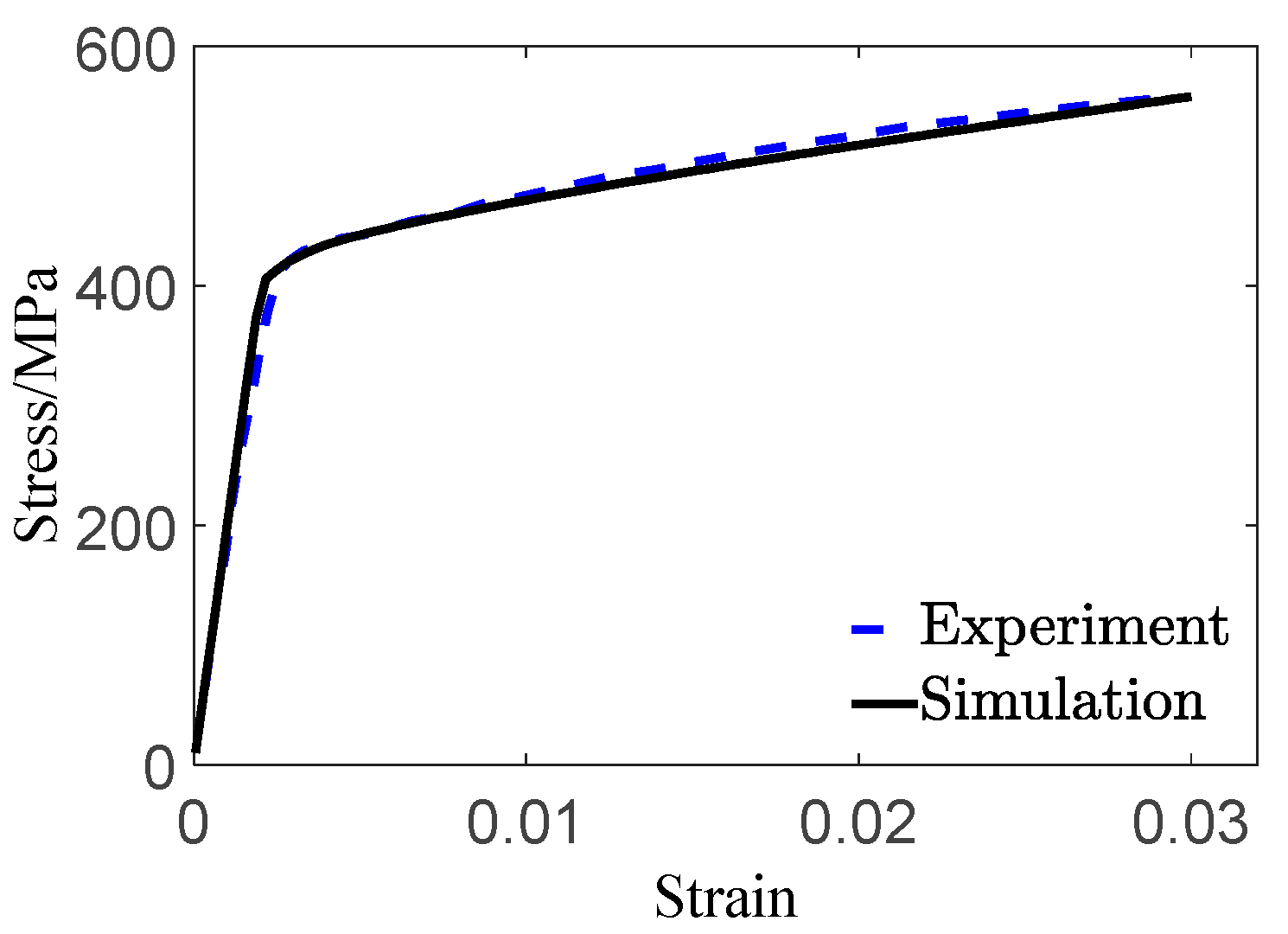
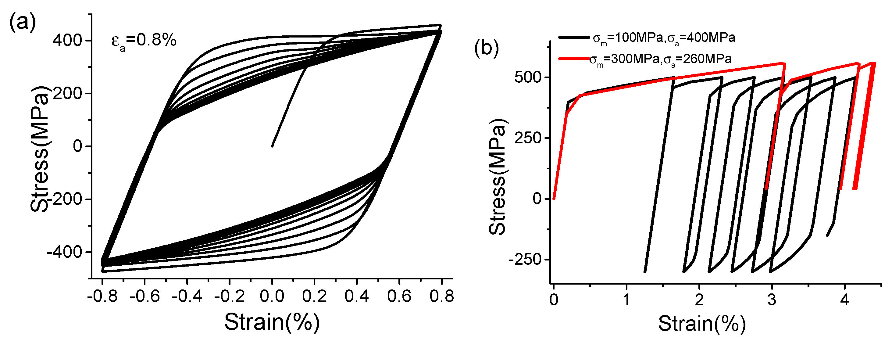
In Koo’s work [26], some mechanical tests of AISI 52100 were conducted; thus, in this work, parameters in the constitutive model are obtained based on the experimental data from their work. In addition, the parameters in the elastic damage evolution rule are obtained by combining the torsional fatigue S-N curve with the integration of damage laws according to Walvekar’s work [15]. As for parameters in the plastic damage rule, the results from Park’s work [27] were used. Therefore, all parameters in the damage-coupled constitutive model are shown in Table 1.

2.4. Validation

In order to assess the precision of the developed model, validation has been conducted. The adopted FE models are shown in Figure 2. Figure 3 presents the comparison between simulation and experimental results for the tensile test, which demonstrates a high level of agreement. Figure 4 illustrates the cyclic behavior of AISI 52100 under different loading conditions. As detailed cyclic testing data could not be found in the public domain, no comparison has been made. However, it is evident that asymmetrical loading leads to accumulated inelastic deformation and will facilitate fatigue failure. Figure 5 displays the experimentally obtained τa- N curve reported in ref. [28], with red symbols indicating the predicted fatigue lifetime using the proposed model in this work. The results show great agreement with an acceptable discrepancy. Overall, it is highly convincing that the developed model is reliable for use in RCF analysis.

3. Rolling Contact Stress Simulation

3.1. The Finite Element Contact Model

In this case, a double-row tapered roller bearing is employed in the axle box of the high-speed EMU, and the relevant parameters are presented in Table 2. Based on the measured data of the loading exerted on the axle box bearing during the normal operation of the EMU, it has been determined that the maximum radial loading borne by the axle box bearing is 66 kN, and the maximum axial loading is 12 kN, which is under the loading condition of C/P = 2.29. According to Liu’s work [29,30], the distribution relationship of the loading inside the bearing indicates that the maximum contact load between the roller and the outer ring is 12.49 kN, making it the most susceptible to RCF failure. A schematic diagram illustrating the contact between the roller and outer ring is depicted in Figure 6a.
Considering the uniformity of the loading distribution along the axial direction, the aforementioned model can be simplified as a line contact. Under the assumption of plane strain condition, it could be further simplified as two deformable circles with different radii of curvature in contact with each other, which is commonly observed in roller bearings. Based on the Hertzian contact theory, this simplified model can be represented as half a circle in contact with an infinite half plane, as illustrated in Figure 6b. In this representation, the half circle represents the roller, and the half plane represents the outer ring. Consequently, as shown in Figure 7, the plane strain element CPE3 is utilized. To strike a balance between accuracy and efficiency, an element size of 12 μm is employed in the contact region, while a relatively coarser mesh is utilized away from the contact region. Since both the roller and outer ring are made of AISI-52100 steel, the elastic–plastic constitutive model described in Section 2 is implemented through user subroutine UMAT in ABAUQS. All the displacements at the bottom of the outer ring are fixed, and a constant force p is applied at the coupling reference point along the Y-axis to simulate the contact behavior.

3.2. Simulation Results and Analysis

According to the Hertz contact theory, the maximum contact pressure between the outer ring and the roller can be calculated assuming fully elastic deformation, resulting in a value of 892.39 MPa with a half-contact width of 0.178 mm. However, for this FE analysis, plastic deformation is taken into consideration. The distribution of the contact pressure is depicted in Figure 8a, with the obtained maximum contact pressure of 817.9 MPa and a half-contact width of 0.225 mm. This corresponds to a 7% error when compared to the Hertz theoretical solution. It is noticeable that the maximum contact pressure of FE is lower than the one of the Hertz theoretical solution, which is reasonable as the FE model considers plastic deformation, resulting in a larger deformation zone and lower the maximum elastic increment, subsequently reducing the stress level. Figure 8b and Figure 9 illustrate the distribution of Mises stress and stress components σxx (S11), σyy (S22), σyy (S33) and σxy (S12), which is stereotyped in contact analysis. The normal stress components (σxx and σzz) inside the contact body decrease with increasing depth. However, σyy is slightly different as it reaches a peak value very close to the surface and then decreases with increasing depth. Additionally, the shear stress component (σxy) reaches its peak value at the subsurface of about 0.5a depth. It is noteworthy that the distribution of σxy on both sides of the y-axis is equal in magnitude but opposite in direction, causing the material to experience alternating shear stress during the rolling process, ultimately leading to fatigue failure.
In conclusion, the FE model accurately simulates the static contact between the roller and outer ring. This model will be further utilized for the RCF analysis of a high-speed EMU axle box bearing, as detailed in Section 4.1.

4. RCF Failure Analysis

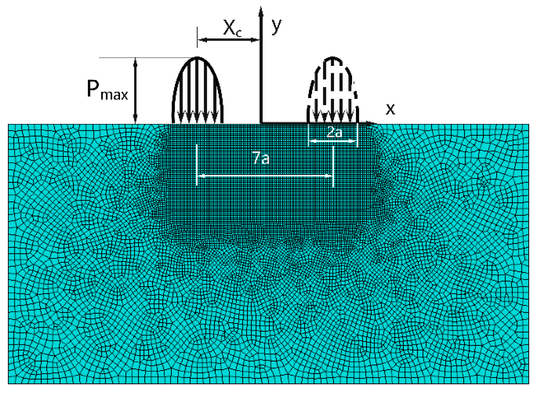
4.1. The Finite Element Contact Model

In this study, an equivalent one-body rolling contact process is utilized to simulate the RCF behavior of the high-speed EMU axle box bearing in order to reduce computational costs. This method, originally proposed by Bhargava et al. [31], is schematically illustrated in Figure 10. As a result, the contact pressure p(x), can be expressed as follows:
p ( x ) = p max 1 x x c a 2
It will be implemented as a boundary condition that transverses across the contact surface during a period stipulated in FE analysis. In Equation (14), x represents the coordinate on the surface, pmax denotes the pressure at the center xc of the contact pressure distribution, and a indicates the semi-contact width.

4.2. Results of the RCF Simulation

The simulation results of RCF are presented in Figure 11 and Figure 12. Figure 11 displays the evolution of damage at the crack initiation point. Before reaching approximately 1 ×   10 8 cycles, the damage remains relatively small. However, after approximately 2 ×   10 8 cycles, the damage rapidly increases and reaches the criterion for crack initiation.
Figure 12 demonstrates the development of the failure zone due to RCF damage as the number of rolling contact cycles increases. It can be observed that the first element to reach the damage threshold Dc = 0.95 is located at the subsurface, approximately at a depth of 0.1 mm, in the region of maximum Mises stress. This number of cycles, denoted as the initiation lifetime (Ni = 2.551 ×   10 8 cycles), signifies the time point at which the crack initiates, as shown in Figure 12a. Subsequently, and increasing number of elements suffer damage accumulation. Some elements gradually reach their limit and lose their load capacity, ultimately forming the crack. Considering D ≥ 0.2 as a significant damage value, it can be observed that the damaged region expands gradually, foreshadowing the path of the crack. As illustrated in Figure 12b–e, the crack propagates towards the deep zone as well as the surface almost simultaneously. Once the crack extends to the surface, it bifurcates, with one branch perpendicular to the surface and the other parallel to the surface, as shown in Figure 12f. Furthermore, the crack generally propagates parallel to the surface more quickly and eventually forms spalling. It is consistent with the experimental observations [32]. In this work, it is defined that once the crack reaches the surface, spalling is considered to have occurred, resulting in failure. Therefore, the corresponding number of cycles is considered to be the total RCF lifetime. The number of cycles from the crack initiation to the occurrence of surface spalling is regarded as the crack propagation life.
Although the spalling is not fully formed in the simulation, it is reasonable and acceptable to conclude the simulation at this point. There are two main reasons for this decision: Firstly, from a computational perspective, when a large number of elements lose their load capacity, it can lead to severe convergence problems and significantly increase computational costs. However, the remaining propagation lifetime compared to the overall RCF lifetime is almost negligible. Secondly, in reality, once the crack reaches the surface, lubricants will enter the crack, forming a high-pressure chamber upon re-contacting. This greatly facilitates crack propagation and results in spalling occurring rapidly.
Hence, based on the simulation results, the predicted crack initiation lifetime of the EMU axle box rolling bearing is 2.551 ×   10 8 cycles, the crack propagation life is 2.8 ×   10 7 cycles, and the total lifetime is 2.831 ×   10 8 cycles. In terms of mileage for high-speed EMU, this corresponds to approximately 6.89 ×   10 5 km, 7.56 ×   10 4 km and 7.65 ×   10 5 km, respectively. These results meet the specifications of the maintenance standard order for the EMU bearing and can be considered to be reasonable.

5. Discussion

Since the RCF analysis method proposed in this study considers both elastic damage resulting from shear stress and plastic damage arising from plastic deformation, it is necessary to discuss the individual contributions of each to the damage accumulation. Figure 13 illustrates the evolution of the elastic damage and the plastic damage of the first failed elements with an increasing number of loading cycles in FEM simulations in two cases: (a) torsional fatigue case with a semi-range stress of 106 psi, and (b) the aforementioned contact fatigue case. It is revealed that under torsional loading (Figure 13a), the stress state predominantly consists of pure shear stress; thus, elastic damage gradually accumulates and dominates. The plastic damage remains at a very low level during more than 90% of the crack initiation life, and increases dramatically near the failure point due to the deterioration of material properties. This indicates that the contribution of plastic damage is almost negligible. Therefore, many studies focusing on torsional fatigue lifetime prediction only consider elastic damage related to the shear stress range and also can achieve acceptable accuracy.
However, in the case of contact fatigue, which is well-known for its multi-axial and non-proportional stress state and highly localized plastic deformation, the situation is different. As depicted in Figure 13b, it is evident that with an increase in rolling contact cycles, plastic damage becomes dominant, while elastic damage occupies a very little portion. If plastic damage is not taken into account, the RCF life of the bearings used in high-speed EMU would be estimated to be around 2.5 ×   10 7 km. Additionally, if employing the standard of ISO 281, considering the normal operation condition of EMU, the bearing life is calculated as 8.8 ×   10 7 km. However, some relevant safety regulations of high-speed EMU state that the total mileage of bearing operation shall not exceed a fourth-level maintenance cycle, which is around 1.2 ×   10 6 km. Therefore, it can be concluded that the predictions made without incorporating plastic damage, as well as those based on the standard of ISO 281, seem highly overpredicted.

6. Conclusions

In this study, a damage-coupled elastic–plastic constitutive model for a high-speed EMU axle box bearing was developed to investigate its contact fatigue behavior. The total damage was divided into elastic damage related to shear stress range and plastic damage associated with plastic deformation. The proposed model was validated by comparing the simulation results with experimental data. The main conclusions of this study can be summarized as follows:
(1)
The maximum contact pressure obtained from the proposed constitutive model is lower than the one calculated according to Hertz contact theory. This indicates that the presence of plastic deformation affects the contact behavior and reduces the maximum contact pressure.
(2)
The crack initiation occurs at the subsurface, at a depth of around 0.1 mm, approximately in the region of maximum Mises stress. The crack primarily extends towards the contact surface and then propagates parallel to the surface. This crack propagation behavior is consistent with experimental observations.
(3)
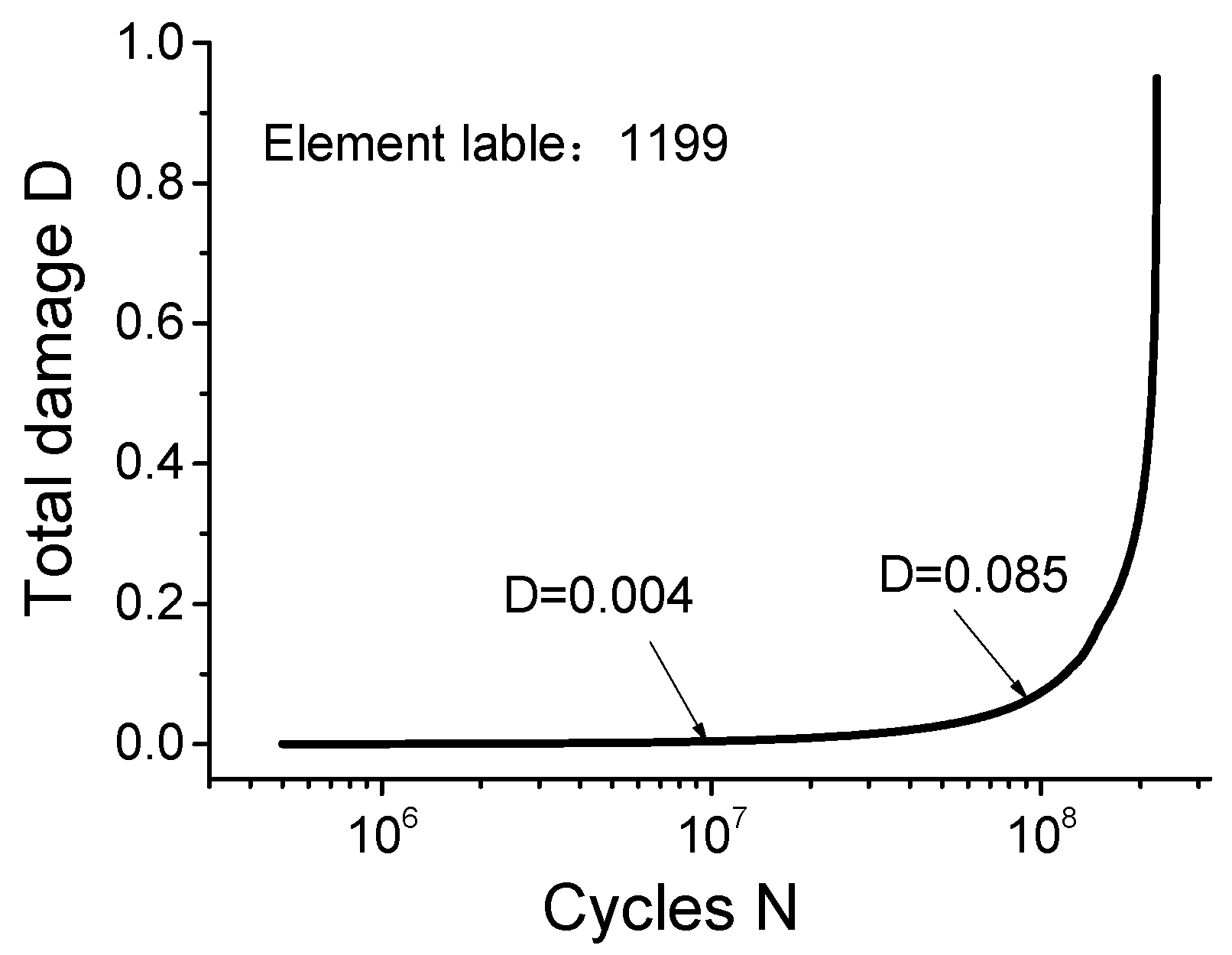
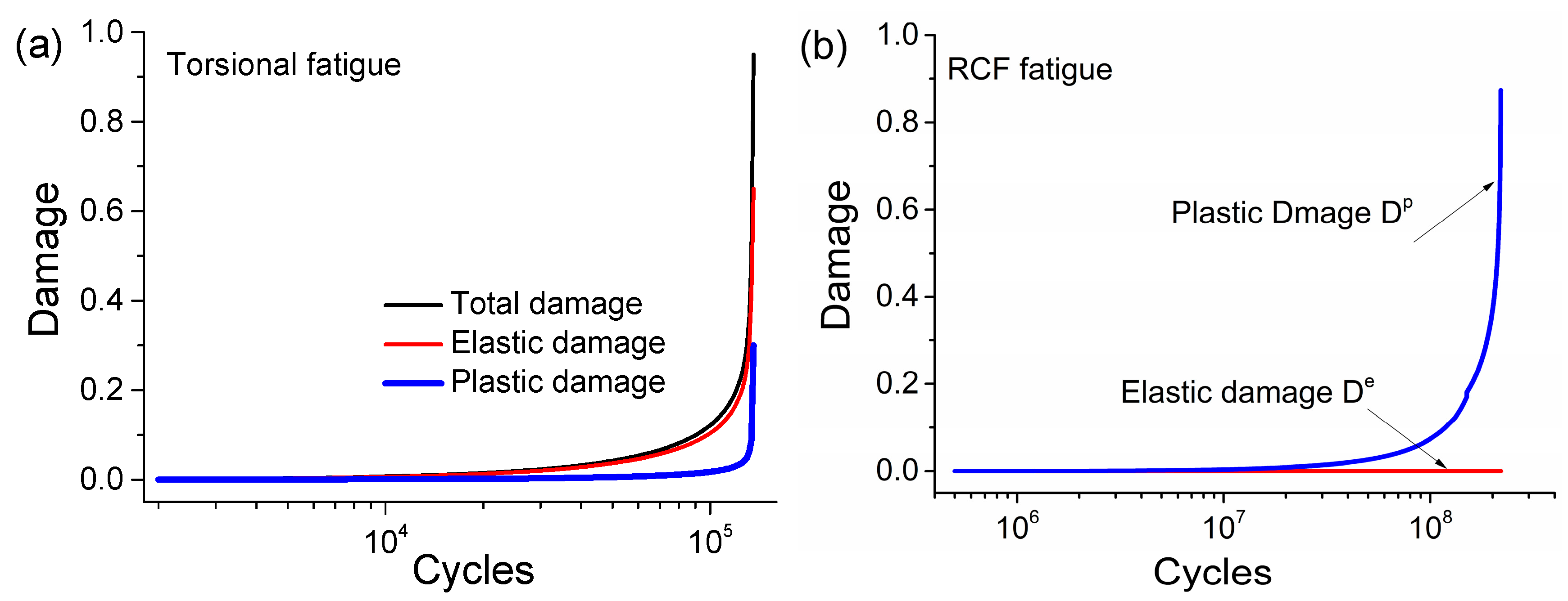
Since the contact loading is not heavy, there is only slight plastic damage generated during the early loading cycles. However, it finally becomes considerable because of the deterioration of material mechanical properties and gradual plastic deformation.
(4)
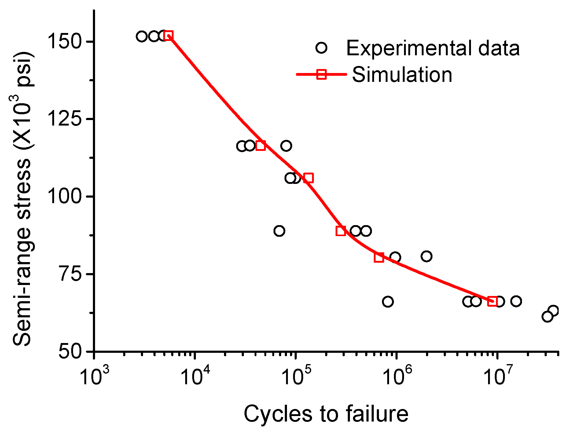
The predicted RCF life of the high-speed EMU axle box bearing using the proposed model is more reasonable. By considering both elastic and plastic damage, the model provides a more accurate estimation of the bearing’s fatigue life.
Overall, the developed damage-coupled elastic–plastic constitutive model can enhance our understanding of the contact fatigue behavior of high-speed EMU axle box bearings and improve the prediction of their fatigue life. In the future, the influence of residual stresses will be incorporated and microstructural alterations will be investigated in order to enhance the RCF analysis.

Author Contributions

Conceptualization, L.M. and J.L.; methodology, L.M. and F.G.; validation, L.M., X.L. and X.Z.; investigation, J.L.; writing—original draft preparation, L.M; writing—review and editing, L.M. and X.Z. All authors have read and agreed to the published version of the manuscript.

Funding

Supported by the Natural Science Foundation of Shandong Province (Grant No. ZR2021QE214) and the National Natural Science Foundation of China (Grant No. 52205200).

Data Availability Statement

Data are contained within the article.

Conflicts of Interest

The authors declare no conflict of interest.

References

  1. Fu, H.; Cui, Y.; Zhang, C.; Zhang, H. Research progress of rolling contact fatigue of bearing steels. China Metall. 2020, 30, 13. [Google Scholar]
  2. El Laithy, M.; Wang, L.; Harvey, T.J.; Vierneusel, B.; Correns, M.; Blass, T. Further understanding of rolling contact fatigue in rolling element bearings—A review. Tribol. Int. 2019, 140, 105849. [Google Scholar] [CrossRef]
  3. El Laithy, M.; Wang, L.; Harvey, T.J.; Vierneusel, B. Re-investigation of dark etching regions and white etching bands in SAE 52100 bearing steel due to rolling contact fatigue. Int. J. Fatigue 2020, 136, 105591. [Google Scholar] [CrossRef]
  4. Kang, J.H.; Hosseinkhani, B.; Rivera-Diaz-Del-Castillo, P.E.J. Rolling contact fatigue in bearings: Multiscale overview. Mater. Sci. Technol. 2012, 28, 44–49. [Google Scholar] [CrossRef]
  5. Bhattacharyya, A.; Subhash, G.; Arakere, N. Evolution of subsurface plastic zone due to rolling contact fatigue of M-50 NiL case hardened bearing steel. Int. J. Fatigue 2014, 59, 102–113. [Google Scholar] [CrossRef]
  6. Pandkar, A.S.; Arakere, N.; Subhash, G. Microstructure-sensitive accumulation of plastic strain due to ratcheting in bearing steels subject to Rolling Contact Fatigue. Int. J. Fatigue 2014, 63, 191–202. [Google Scholar] [CrossRef]
  7. Pandkar, A.S.; Arakere, N.; Subhash, G. Ratcheting-based microstructure-sensitive modeling of the cyclic hardening response of case-hardened bearing steels subject to Rolling Contact Fatigue. Int. J. Fatigue 2015, 73, 119–131. [Google Scholar] [CrossRef]
  8. Ruijie, Z.; Chunlei, Z.; Bo, L.; Xubiao, W.; Xiaofeng, L.; Yanguo, L.; Fucheng, Z. Research progress on rolling contact fatigue damage of bainitic rail steel. Engi. Fail. Anal. 2023, 143, 106875. [Google Scholar] [CrossRef]
  9. Arakere, N.K. Gigacycle rolling contact fatigue of bearing steels: A review. Int. J. Fatigue 2016, 93, 238–249. [Google Scholar] [CrossRef]
  10. Dong, S.; Yu, Q.; Jiang, Y.; Dong, J.; Wang, F.; Jin, L.; Ding, W. Characteristic cyclic plastic deformation in ZK60 magnesium alloy. Int. J. Plast. 2017, 91, 25–47. [Google Scholar] [CrossRef] [Green Version]
  11. Bhatti, N.A.; Pereira, K.; Abdel Wahab, M. A continuum damage mechanics approach for fretting fatigue under out of phase loading. Tribol. Int. 2018, 117, 39–51. [Google Scholar] [CrossRef]
  12. Lorenz, S.J.; Sadeghi, F.; Trivedi, H.K.; Rosado, L.; Wang, C. A continuum damage mechanics finite element model for investigating effects of surface roughness on rolling contact fatigue. Int. J. Fatigue 2021, 143, 105986. [Google Scholar] [CrossRef]
  13. Yao, Y.; He, X.; Keer, L.M.; Fine, M.E. A continuum damage mechanics-based unified creep and plasticity model for solder materials. Acta Mater. 2015, 83, 160–168. [Google Scholar] [CrossRef]
  14. Shintaku, Y.; Tsutsumi, S.; Terada, K. A CDM-like constitutive law for predicting degradation of strength and ductility of steel subjected to cyclic loading. Int. J. Plast. 2022, 153, 103237. [Google Scholar] [CrossRef]
  15. Walvekar, A.A.; Paulson, N.; Sadeghi, F.; Weinzapfel, N.; Correns, M.; Dinkel, M. A New Approach for Fatigue Damage Modeling of Subsurface-Initiated Spalling in Large Rolling Contacts. J. Tribol. 2017, 139, 011101. [Google Scholar] [CrossRef]
  16. Li, F.; Hu, W.; Meng, Q.; Zhan, Z.; Shen, F. A new damage-mechanics-based model for rolling contact fatigue analysis of cylindrical roller bearing. Tribol. Int. 2018, 120, 105–114. [Google Scholar] [CrossRef]
  17. Warhadpande, A.; Sadeghi, F.; Kotzalas, M.N.; Doll, G. Effects of plasticity on subsurface initiated spalling in rolling contact fatigue. Int. J. Fatigue 2012, 36, 80–95. [Google Scholar] [CrossRef]
  18. He, H.; Liu, H.; Zhu, C.; Wei, P.; Sun, Z. Study of rolling contact fatigue behavior of a wind turbine gear based on damage-coupled elastic-plastic model. Int. J. Mech. Sci. 2018, 141, 512–519. [Google Scholar] [CrossRef]
  19. Shen, F.; Hu, W.; Meng, Q.; Zhang, M. A new damage mechanics based approach to fatigue life prediction and its engineering application. Acta Mech. Solida Sin. 2015, 28, 510–520. [Google Scholar] [CrossRef]
  20. Shen, F.; Hu, W.; Meng, Q. A damage mechanics approach to fretting fatigue life prediction with consideration of elastic–plastic damage model and wear. Tribol. Int. 2015, 82, 176–190. [Google Scholar] [CrossRef]
  21. Shen, F.; Zhou, K. An elasto-plastic-damage model for initiation and propagation of spalling in rolling bearings. Int. J. Mech. Sci. 2019, 161–162, 105058. [Google Scholar] [CrossRef]
  22. Lemaitre, J.; Chaboche, J.L. Mechanics of Solid Materials; Cambridge University Press: Cambridge, UK, 1990. [Google Scholar]
  23. Zhao, B.; Shen, F.; Cui, Y.; Xie, Y.; Zhou, K. Damage analysis for an elastic-plastic body in cylindrical contact with a rigid plane. Tribol. Int. 2017, 115, 18–27. [Google Scholar] [CrossRef]
  24. Zhan, Z.; Meng, Q.; Hu, W.; Sun, Y.; Shen, F.; Zhang, Y. Continuum damage mechanics based approach to study the effects of the scarf angle, surface friction and clamping force over the fatigue life of scarf bolted joints. Int. J. Fatigue 2017, 102, 59–78. [Google Scholar] [CrossRef]
  25. Raje, N.; Sadeghi, F.; Rateick, R.G. A Statistical Damage Mechanics Model for Subsurface Initiated Spalling in Rolling Contacts. J. Tribol. 2008, 130, 786–791. [Google Scholar] [CrossRef]
  26. Koo, S.; Han, J.; Marimuthu, K.P.; Lee, H. Determination of Chaboche combined hardening parameters with dual backstress for ratcheting evaluation of AISI 52100 bearing steel. Int. J. Fatigue 2019, 122, 152–163. [Google Scholar] [CrossRef]
  27. Park, J.; Lee, K.; Kang, J.H.; Kang, J.Y.; Hong, S.H.; Kwon, S.W.; Lee, M.G. Hierarchical microstructure based crystal plasticity-continuum damage mechanics approach: Model development and validation of rolling contact fatigue behavior. Int. J. Plast. 2021, 143, 103025. [Google Scholar] [CrossRef]
  28. Styri, H. Fatigue strength of ball bearing races and heat-treated 52100 steel specimens. Proc. Am. Soc. Test. Mater. 1951, 51, 18. [Google Scholar]
  29. Liu, D. Life Prediction Method for EMU Axle Box Bearings Based on Actual Measured Loadings. Int. J. Mech. Eng. 2016, 52, 45. [Google Scholar] [CrossRef]
  30. Liu, D.; Li, Q.; Hu, W.; Pan, W. Fatigue life prediction of the axle box bearings for high-speed trains. DYNA 2017, 92, 7. [Google Scholar]
  31. Bhargava, V.; Hahn, G.T.; Rubin, C.A. An Elastic-Plastic Finite Element Model of Rolling Contact, Part 1: Analysis of Single Contacts. J. Appl. Mech. 1985, 52, 67–74. [Google Scholar] [CrossRef]
  32. Rosado, L.; Forster, N.H.; Thompson, K.L.; Cooke, J.W. Rolling Contact Fatigue Life and Spall Propagation of AISI M50, M50NiL, and AISI 52100, Part I: Experimental Results. Tribol. Trans. 2009, 53, 29–41. [Google Scholar] [CrossRef]
Figure 1. Asymmetric cyclic loading on the rolling bearings.
Lubricants 11 00330 g001
Figure 2. FE model for validation: (a) single element; (b) torsion specimen.
Lubricants 11 00330 g002
Figure 3. Tensile experimental and simulated data of the bearing steel AISI 52100.
Lubricants 11 00330 g003
Figure 4. Cyclic behavior simulation of the bearing steel AISI 52100: (a) for strain-controlled condition; (b) for stress-controlled condition (ratchetting occurs).
Lubricants 11 00330 g004
Figure 5. Comparison of S–N curve for AISI-52100 bearing steel in completely reversed torsion.
Lubricants 11 00330 g005
Figure 6. Schematic diagram of rolling contact between roller and outer ring: (a) 3D model; (b) 2D model.
Lubricants 11 00330 g006
Figure 7. Geometry of two-dimensional contact model for rolling contact stress analysis.
Lubricants 11 00330 g007
Figure 8. Simulation results of (a) contact pressure at the contact surface; (b) σxx, σyy and σzz at the contact center.
Lubricants 11 00330 g008
Figure 9. Distribution of contact stress: (a) Mises; (b) S12; (c) S11; (d) S22.
Lubricants 11 00330 g009
Figure 10. Illustration of the one-body FE model for RCF analysis.
Lubricants 11 00330 g010
Figure 11. Evolution of damage at crack initiation point.
Lubricants 11 00330 g011
Figure 12. Simulation of the formation of subsurface spalling.
Lubricants 11 00330 g012
Figure 13. Evolution of elastic and plastic damage of two cases: (a) torsional fatigue; (b) RCF fatigue.
Lubricants 11 00330 g013
Table 1. Material parameters for AISI 52100.
Parameters
C 1 = 28.02   G P a ,   C 2 = 2.14   G P a ,   C 3 = 1.56   G P a ,   C 4 = 3.07   G P a ; γ 1 = 1180.95 ,   γ 2 = 99.4 ,   γ 3 = 52.43 ,   γ 4 = 37.04 ; Q 0 = 400 ,   E = 200   G P a ,   ν = 0.3 ,   μ s a t = 0.1 ,   k = 25 ; M = 4 ,   Q = 150 ,   b = 15 ; m = 10.1 ,   τ R = 6113   M P a ; S = 89.9   M P a ,   q = 3.2 .
Table 2. Related parameters of the selected bearing.
Number of Roller RowsNumber of Rollers in a Single-Row BearingEquivalent Length of Roller (mm)Contact Angle between Roller and Inner Raceway (°)
21952.89
Fillet diameter of roller (mm)The maximum diameter of roller (mm)The maximum diameter of roller (mm)Contact angle between roller and outer raceway (°)
185272512
Disclaimer/Publisher’s Note: The statements, opinions and data contained in all publications are solely those of the individual author(s) and contributor(s) and not of MDPI and/or the editor(s). MDPI and/or the editor(s) disclaim responsibility for any injury to people or property resulting from any ideas, methods, instructions or products referred to in the content.

