Article

A Multi-Scale Investigation to Predict the Dynamic Instabilities Induced by Frictional Contact

by
Farouk Maaboudallah
* and
Noureddine Atalla
*
Department of Mechanical Engineering, Groupe d’Acoustique de l’Université de Sherbrooke (GAUS), Sherbrooke, QC J1K 2R1, Canada
*
Authors to whom correspondence should be addressed.
Lubricants 2023, 11(8), 344; https://doi.org/10.3390/lubricants11080344
Submission received: 13 June 2023 / Revised: 3 August 2023 / Accepted: 8 August 2023 / Published: 11 August 2023
(This article belongs to the Special Issue Advances in Contact Mechanics)

Abstract

:
We propose a new variational formulation to model and predict friction-induced vibrations. The multi-scale computational framework exploits the results of (i) the roughness measurements and (ii) the micro-scale contact simulations, using the boundary element method, to enrich the contact zone of the macroscopic finite element model of rubbing systems with nominally flat contact boundaries. The resulting finite elements at the contact interface of the macroscopic model include (i) a modified normal gap and (ii) a micro-scale description of the contact law (i.e., pressure gap) derived by solving the frictionless contact problem on a rough surface indenting a rigid half-plane. The method is applied to a disc brake system to show its robustness in comparison with classical deterministic formulations. With respect to the traditional complex eigenvalues analysis, the proposed multi-scale approach shows that the inclusion of roughness significantly improves the results at low frequencies. In this panorama, any improvement of dynamic instabilities predictions should be based on an uncertainty analysis incorporating roughness combined with other parameters such as friction coefficient and shear moduli of the pads, rather than on roughness itself.

1. Introduction

The frictional contact problem plays a major role in engineering applications, whether in studying the fretting fatigue in dovetail blade roots in aeronautics [1], valve systems for nuclear cooling [2] or braking systems in the automotive industry [3,4,5]. The mechanical behavior of frictional systems mentioned above is micro-scale dependent. Their performance is conditioned by numerous microscopic phenomena, such as roughness, progressive damage of asperities as well as resulting debris [6,7]. For instance, it was shown in [8] that the macroscopic behavior of the braking system is strongly influenced by the microscopic contact properties, which involves the roughness of the sliding interfaces. Hence, it is important to review and to overcome the assumption of perfectly flat surfaces by taking into account the statistical characteristics of rough surfaces.
In general, the modeling of rough surfaces requires the knowledge of two functions: (i) the height distribution function (HDF) [9] and (ii) the spatial function, also known by the autocorrelation function (ACF) or its Fourier transform, which is called the power spectral density (PSD) function [10]. The first one characterizes the roughness through the average height parameters [11,12], while the second describes the spacial arrangement and the variation of the asperities, which often depicts a fractal behavior [13,14]. Most rough surfaces have a self-affine property, which means that the profile remains similar under different magnification [13,15]. The latter can be decoded by a PSD having a power-law shape as a function of the wavenumber (or wavelength) with a potential plateau characterized by a longer wavelength, namely the long-distance roll-off wavevector [16,17,18].
With regard to the mechanical contact models, the first contribution goes back a century with the widely used Hertz theory [19,20]. This theory assumes perfect smooth contacting surfaces, and hence, it is not valid for rough surfaces since it failed to give a reasonable estimation for the real contact area and for the pressure-gap behavior. The strong deviation from the perfect contact assumption led researchers to develop more realistic models to take into account the roughness. The first asperity-based models, pioneered by research work [9,21], are based on a statistical method and the random process theory introduced for the first time in [10,22]. The concept of their approach is to transform the problem of two contacting rough surfaces to a deformable rough one in contact with a rigid plane. Then, the roughness is modeled by a number of isolated spherical asperities with the same radius, and their height is described randomly following a given probability density function. The asperity-based models provide a good approximate solution for the evolution of the contact area especially in the case of a small load [23]. However, their main drawback is the omission of interactions between the asperities, which can lead to an overestimation of the contact pressure. With the development of advanced analytical models [24,25,26,27], interactions between asperities can be taken into account. The coalescence of asperities is another effect that has to be considered for a realistic representation. In fact, the contact spots do not grow independently in reality. They merge and, therefore, contact patches develop. Afferante et al. [28] proposed a suitable approach to address the coalescence of two contacting spots. The concept of their approach is that the asperities with overlapping contacts spots are eliminated and corrected with a single contact patch, namely the equivalent asperity. It should be noted that the contact area of the new asperity includes the area of the suppressed contact spots. In parallel to the aforementioned analytical models, Person proposed an ingenious theory [13,14,29] to tackle the contact problem for rough surfaces. The fundamental concept of the fractal approach is to solve the contact problem at different scale by introducing the evolution of contact pressure probability density. The author mentioned in [14] that the latter satisfies a diffusion-like equation with an appropriate boundary conditions. Persson’s approach has been criticized on the pretext that the proof of the diffusion-like equation is not rigorous, since it is derived assuming full contact and used with the boundary condition on its solution to model the partial contact. In general, it provides a solution that is quantitatively inconsistent with the available solutions, which leads to somewhat smaller contact areas and, thus, greater pressures than those found in the literature [30,31].
The development of computing facilities has enabled the emergence of accurate numerical models that, unlike previous analytical models, are free of assumptions. A couple of numerical techniques can be distinguished: (i) the finite element method (FEM) [2,32], (ii) the boundary element method (BEM) [33] and (iii) Green’s function molecular dynamics (GFMD) [34,35]. The first class of methods is the most used and the most accurate technique. It is based on the optimization of the variational formulation of the contact problem [36,37]. In general, it is applied to a representative volume element (RVE) of the rough surface and requires intensive computing, since the element size should be small enough to capture the asperity waviness and the roughness [2]. The last two classes are more attractive for modeling rough contacts. This is essentially due to the fact that only the rough surface needs to be discretized, and not the bulk, as required by FEM, which allows increasing the mesh density and, hence, perform more accurate studies. Despite these advances, BEM and GFMD are based on the fundamental elasticity theory. The generalization of these approaches to take into account non-linearities is sometimes possible but is not an easy task. For a detailed review, see [32,38].
In the industrial context, FEM is mainly used to model and predict the behavior of frictional systems. In most applications, the contact interfaces are assumed to be flat and have dimensions generally much larger than the microscopic scale of the roughness. Therefore, explicit integration of the roughness in these interfaces is not possible, since it generates extremely dense meshes which, in turn, will increase the computation time. In consequence, authors in literature abandon the classical path of explicitly modeling surface roughness by proposing multi-scale embedded strategies to enhance the computational cost of the direct FEM. For instance, the authors in [39,40,41] suggested integrating the micro-mechanical contact laws in the sliding interfaces. The fundamental concept behind this approach is to derive and then integrate the constitutive contact equations using the homogenization process, which describes the microscopic behavior within the contact zone. Bonari et al. [42] also developed a novel multi-scale formulation that takes advantage of micro-scale simulations to enrich the contact interfaces of macroscopic FE models. The developed method allows taking into account any desirable topography to model efficiently and within a reasonable CPU time the frictional system. In the same spirit, Paggi et Reinoso [43] introduced a new idea that takes into account the shape of the roughness to correct the normal separation in macroscopic contact interfaces. Tison et al. [3,44] investigated the use of rough contact to model the dynamic behavior of a disc brake system. They used a multi-scale framework based on the random field theory [45,46]. The integration of the latter within the complex eigenvalues analysis (CEA) provides a remarkable prediction, which allowed for better correlation with the experimental results.
Regarding the dynamic instabilities that represent the core of this paper, it is well accepted that the frictional contact influences drastically the global dynamic behavior of a rubbing system [47,48]. Taking into account the contribution of the frictional contact to the system’s overall stiffness matrix, dynamic instabilities are predicted using two methods: (i) transient analysis and (ii) CEA. The latter is the most widely used in the industry, as it offers a very good compromise between computation time and accuracy. Indeed, CEA approach uses the mode coupling theory to evaluate the stability of the rubbing system. Thus, it will be unstable if and only if at least one predicted vibratory mode has a strictly positive real part [49]. Since the frictional contact problem is closely linked to dynamic instabilities, the contribution of the roughness should be taken into account and investigated in detail for a potential enhancement of the deterministic CEA. As pointed above, the classic FEM is time consuming since the mesh should be fine enough to capture all the physics of the rough surface. A novel strategy has therefore to be found to fulfill two main criteria: (i) an accurate prediction of the dynamic instabilities and (ii) a reasonable computational cost. In this light, the main contribution of this paper is to suggest a simple alternative approach, highly flexible, that allows accurately and reliably predicting the dynamic instabilities of an industrial braking system. The proposed multi-scale finite element formulation, presented in detail in Section 2, abandons the traditional path of explicitly introducing roughness by means of the asperities in the contacting interfaces. In fact, it considers that the contact interfaces of a large-scale FE model are perfectly flat and smooth. But each element (contact patch) is enriched by adding two contributions, namely (i) the pressure-gap contact law and (ii) the contact element activation. The first one is derived using BEM on a generated rough surface and is assigned to each patch. The use of micro-scale contact law, for each patch, will modify the penalty method and will introduce the roughness in an implicit manner. The second enhancement is introduced within the normal gap function. Indeed, a critical gap is added to the classic formulation. It is derived from HDF resulting from the topography measurement. The embedded strategy is then applied to a disc brake system in Section 3 to investigate the prediction of dynamic instabilities.

2. Governing Equation

The first section introduces the basic governing equations for the non-linear contact problem. After recalling the general framework of the boundary value problems with constraints, the variational formulation of the weak problem will be presented for the case of frictionless contact problems of two deformable solids. This is the first step of a complex eigenvalues analysis (CEA) where the equilibrium position, u e , is determined. Finally, we will present the principle of our approach, which consists of integrating roughness in macroscopic FE models in order to predict dynamic instabilities of a frictional system in a more realistic way.

2.1. General Framework

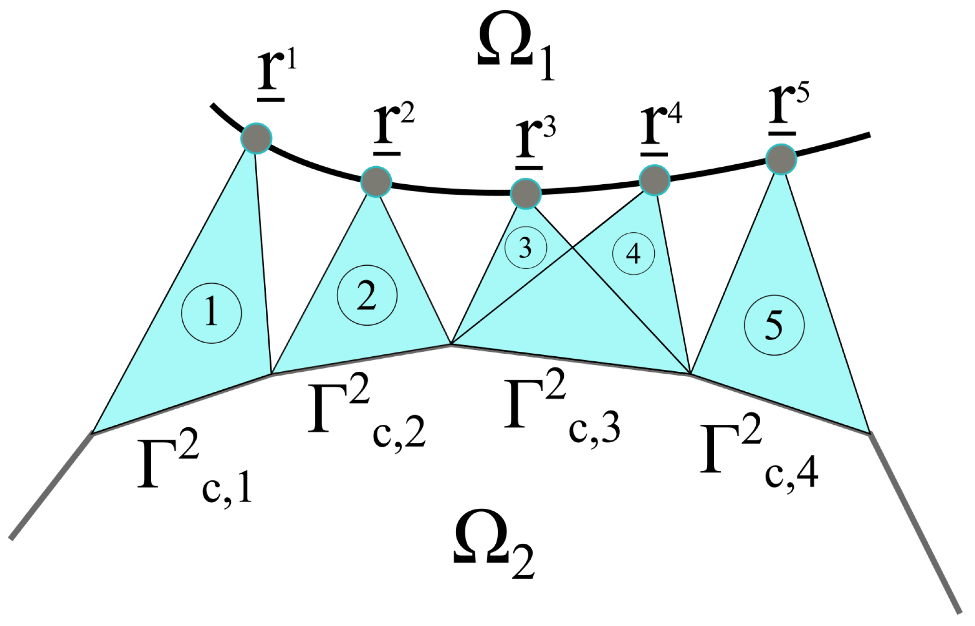
In the framework of continuum mechanics, a solid is modeled by an open domain Ω , which is assumed to be bounded and regular. The boundary of Ω is divided in two parts: (i) the first one denoted Ω u where the Dirichlet boundary conditions are applied and (ii) the second one denoted Ω f where the Neumann boundary conditions are applied. So, without any loss of generality, the formulation of the problem when two deformable bodies Ω 1 and Ω 2 (see Figure 1), with Ω = Ω 1 Ω 2 , come in contact at a single contact zone Ω c is given by a system of elliptical partial differential equations that can be categorized as follows:
  • static balance of momentum equation,
    · σ ̲ ̲ = 0 in Ω = Ω 1 Ω 2 σ ̲ ̲ . n ̲ = σ ̲ 0 at Ω f ,
  • compatibility equations,
    ε ̲ ̲ ( u ̲ ) = 1 2 ( · u ̲ + · u ̲ T ) in Ω = Ω 1 Ω 2 u ̲ = u ̲ 0 at Ω u ,
  • constitutive relation,
    σ ̲ ̲ = C ̲ ̲ 4 : ε ̲ ̲ ( u ̲ ) in Ω = Ω 1 Ω 2 ,
    where σ ̲ ̲ is the Cauchy stress tensor and ε ̲ ̲ is the so-called small strain tensor, which is related to the displacement field u ̲ . σ ̲ 0 and u ̲ 0 are the stress and the displacement field imposed on the boundaries Ω f and Ω u , respectively. C ̲ ̲ 4 is the Hook fourth-order tensor for the considered domain.
In the case of a frictionless contact between two bodies, a relevant complimentary conditions should be formulated. The latter defines the geometrical and the mechanical state of the two contacting surfaces. The complimentary conditions are called Hertz–Signorini–Moreau conditions and can be written as
g 0 , σ n 0 , g . σ n = 0 , σ ̲ t = 0 at Ω c = Γ c 1 Γ c 2 ,
where σ n and σ ̲ t refer to the normal and the tangential contact stresses, respectively. g refers to the gap function between the slave and master surfaces. Hence, the Hertz–Signorini–Moreau conditions can be read as the non-penetration–non-adhesion conditions. In other words, if the two bodies Ω 1 and Ω 2 are in contact, then the gap function g is equal to 0 and the normal contact stress σ n is below 0; otherwise, g > 0 and σ n = 0 .

2.2. Variation Formulation of the Frictionless Contact Problem

The statement of the weak formulation for the contact problem is obtained by multiplying the strong form in Equation (1) by a test function v ̲ and integrating over the domain Ω , and we write
Ω · σ ̲ ̲ · v ̲ d Ω = 0 v ̲ V .
By performing integration and applying the divergence theorem, Equation (5) becomes
Ω n ̲ · σ ̲ ̲ · v ̲ d Γ Ω σ ̲ ̲ : v ̲ d Ω = 0 ,
where: is the contraction operation of two second-order tensors and n ̲ denotes the outward normal at the slave surface Γ c 1 . We have n ̲ = ν ̲ where ν ̲ is the outward normal at master surface Γ c 2 (see Figure 1).
Note that by introducing the traction vector σ ̲ 0 , the contact boundary conditions and the virtual displacement δ u ̲ in the test function v ̲ , the first term in Equation (6) may be rewritten as the sum of two main parts: (i) the frictionless contact contribution and (ii) the Neumann boundary condition contribution. Symbolically, we write
Ω c n ̲ · σ ̲ ̲ · δ ( ρ ̲ r ̲ ) d Γ + Ω f σ ̲ 0 · δ u ̲ d Γ Ω σ ̲ ̲ : δ u ̲ d Ω = 0 ,
where ρ ̲ and r ̲ are the displacement vectors of master and slave points, respectively. Furthermore, the quantity r ̲ ρ ̲ is the gap vector describing the position of the slave point r ̲ and his projection into the master surface ρ ̲ .
In the case of a normal gap, g n n ̲ = r ̲ ρ ̲ , the variational form in Equation (7) may be written as follows:
Γ c 1 σ n δ g n d Γ Ω f σ ̲ 0 · δ u ̲ d Γ + Ω σ ̲ ̲ : δ u ̲ d Ω = 0 .
It should be noted that the mathematical constraints of the strong and weak forms are not the same. For the strong form in Equation (1), the Cauchy tensor is required to be smooth enough; i.e., σ ̲ ̲ C 1 ( Ω ) , which is not the case for the weak form in Equation (6). The order of differentiation in the weak formulation is lower than the strong one. In fact, the order of differentiability in the weak integral form is distributed between the Cauchy stress tensor and the test function.
Finally, the balance of virtual work, called also the weak form, for the frictionless contact problem can be formulated as follows:
Find u ̲ U = u ̲ H 1 ( Ω ) u ̲ = u ̲ 0 on Ω u such as
Γ c 1 σ n δ g n d Γ Ω f σ ̲ 0 · δ u ̲ d Γ + Ω σ ̲ ̲ : δ u ̲ d Ω = 0 V = δ u ̲ H 1 ( Ω ) δ u ̲ = 0 on Ω u C = δ u ̲ V ( r ̲ + δ r ̲ ρ ̲ + δ ρ ̲ ) · n ̲ g n 0 ,
where H 1 ( Ω ) denotes the Hilbert space of the first order, δ r ̲ and δ ρ ̲ refer to δ u ̲ but in the contact interface. And, finally, g n 0 represents the initial gap between contacting surfaces.

2.3. Overview of the Embedded Computational Strategy to Include the Roughness on Macro-Scale Model

Under the framework of the finite element method, the formulation in Equation (9) will be solved using the most popular scheme: the penalty method. The goal as mentioned above is to find the equilibrium position due to the frictionless contact (see Section 1 in [4] for more detail).
To approximate the Hertz–Signorini–Moreau condition, the normal contact stress arising at the contact interface will be expressed as a function of the gap using the following approximation:
σ n ( g ) = ε n ( < g > ) = 0 g > 0 , there is no contact ε n ( g ) g 0 , there is contact ,
where ε n is a non-positive, continuous and strictly decreasing function defining the evolution of the contact stresses, σ n , as a function of the gap, g, between the master and the slave surfaces. In the case of the linear penalty method, the function ε n will simply denote the classic contact stiffness (i.e., penalty coefficient). Finally, < · > refers to max { · , 0 } .
The penalty method can be seen as an approximation of the contact constraints. It leads to a small penetration between the slave and master surfaces (see the case when g < 0 in Equation (10)). It should be noted that the definition in Equation (4) will be met if the contact stress is higher for a small penetration. In other words, the penalty method does not restrict the penetration between the contacting surfaces but it resists it. If it is deeper (i.e., g < 0 ), the value of ε n ( g ) will be higher and, hence, the real contact stress (i.e., reaction) will appear.
Under the last assumption, the virtual work in Equation (9) can be divided into the classic solid mechanics part, δ W s , and the contribution from the contact problem, namely δ W c . The weak formulation of the system is obtained using the penalty method. We have
δ W c + δ W s = 0 ,
where
δ W c = Γ c 1 ε n ( < g n > ) δ g n d Γ ,
and
δ W s = Ω σ ̲ ̲ : δ u ̲ d Ω Ω f σ ̲ 0 · δ u ̲ d Γ .
In this paper, the the potential energy of the contact interaction will be formulated as follows:
Π c = 1 2 Γ c 1 ε n ( < ( g n g n c r ) > ) 2 d Γ ,
where g n c r is called the critic gap. It is a value that will be defined for each contact element and from which the latter will be activated. The first enrichment introduced in Equation (14) will allow for a non-homogeneous activation of the contact status for all nodes of the contact interface.
Considering Node-To-Surface (N2S) discretization, the slave surface Γ c 1 can be presented by nodes denoted by r ̲ i and the master one, Γ c 2 , can be discretized as set of segments denoted by Γ c , j 2 . Let us assume that we have N slave points and M master segments. One can observe from Figure 2 that for all slave nodes r ̲ i , one or more master segments Γ c , j 2 can be determined using the normal projection. Hence, the i-th contact element can be defined by a combination of one slave node r ̲ i with its correspondent master segment Γ c , j 2 . By using the last definition and the fact that we have n c contact finite elements, the discretized form of Equation (14) can be rewritten as follows:
Π c 1 2 i = 1 n c Γ c , i 2 ε n i ( < ( g n i g n c r , i ) > ) 2 d Γ ε n i ε n j i j ,
where ε n i denotes the contact law for the i-th contact element. It pairs up the normal contact stress with the gap distance. Note that the contact law from one element to another is not the same. Each contact element will have its own law constituting the second enrichment.
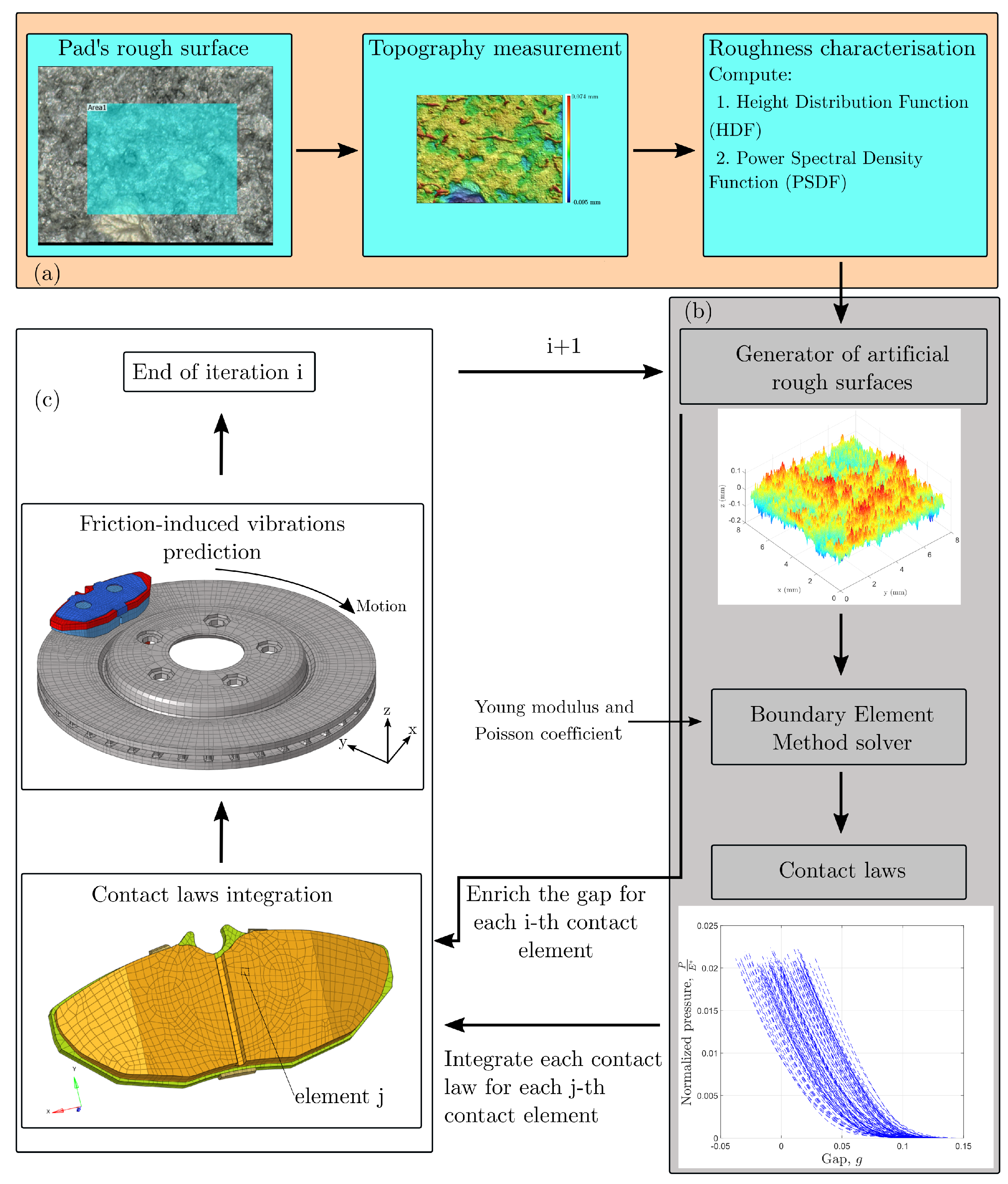
The idea behind the proposed strategy is to integrate the heterogeneity observed in the asperity scale into macroscopic models. In general, the present methodology incorporates three main steps: (i) The first one consists in characterizing the rough surface (the objective of Section 3.1). (ii) The second one aims to solve, at the roughness scale, the frictionless contact problem. This step is important as it allows deriving the pressure-gap’s contact law by taking into account the roughness. Finally, (iii) the third one consists in introducing the height distribution as well as the local behavior of the contact stiffness to enrich the gap, equivalently the contact detection, and the penalty function. The overall procedure is summarized in Figure 3.
In the first step (Figure 3a), the rough surface is characterized for example by using a confocal laser scanning microscopy (CLSM) technique in order to measure the height z of each point. Since the roughness is random [10], the height of the rough surface is considered, in this work, as a random variable (RV) with an independent Cartesian coordinates. The measured realization of the RV will be used to estimate the HDF denoted by P ( z ) . The latter will be introduced in the third step into the macroscopic FE model through the gap function. Practically, the statistics of the rough surface will be transmitted to the FE model using the new form of the normal gap in Equation (14) or (15). Hence, we write
P ( z ) P ( Δ ) ,
where Δ = g n g n c r is a RV. The realization Δ i j of Δ will be assigned for each contact element i.
In a second step (Figure 3b), several rough surfaces will be generated numerically based on the statistics and the spectral analysis of the measured surface. The objective is to apply the BEM in order to solve microscopically the contact problem of the rough surfaces. The purpose of this micro-scale simulation is to compute the micro-mechanical behavior of the contact interface involving the roughness. The latter is modeled by the pressure-gap law for each generated rough surface and injected into the weak form through the function ε n of Equation (10). It is agreed that this requires intensive computation on several rough surfaces, especially if advanced BEM solvers are used to take into account interfacial or material non-linearities such as adhesion or plasticity. Here, the crucial goal is to derive a set of local contact laws, by taking into account the roughness, for each contact element (patch).
Finally, in the last step (Figure 3c), the contact laws as well as the enriched gap function will be assigned to each patch. The integration procedure is the same for both parameters. Indeed, assuming that the contact interface is smooth and flat, the sampled results resulting from the BEM simulations and the measured surface characterization will be embedded within the contact elements. Following the logic of the embedded approach, the roughness will not be represented explicitly in the FE model. It will be included implicitly through the new formulation of the contact gap and the modified penalty function. Next, the enriched FE model can be solved using CEA to compute the dynamic instabilities. In general, the procedure falls into a fully parallelizable loop. After the surface characterization, steps 2 and 3 (Figure 3b,c) can be repeated as many times as needed in order to obtain a representative statistical prediction.

3. Application to a Disc Brake System

In this section, the previously proposed computational strategy is implemented to predict the dynamic behavior of an automotive disc brake system. First, the pad surface is measured by a CLSM. The objective is to characterize the pad surface topography by means of (i) the height distribution function (HDF) and (ii) the power spectral density (PSD) function. Second, a batch of artificial surfaces will be randomly generated based on the previously measured functions (HDF and PSD). The aim is to apply BEM, developed in [50], to predict the contact laws, i.e., the evolution of the load as a function of the gap. These elements will be integrated, toward the end, into a macroscopic FE model of a disc brake to reproduce the heterogeneity observed in the contact interfaces in order to predict the dynamic instabilities induced by friction.

3.1. Pad Surface Characterization

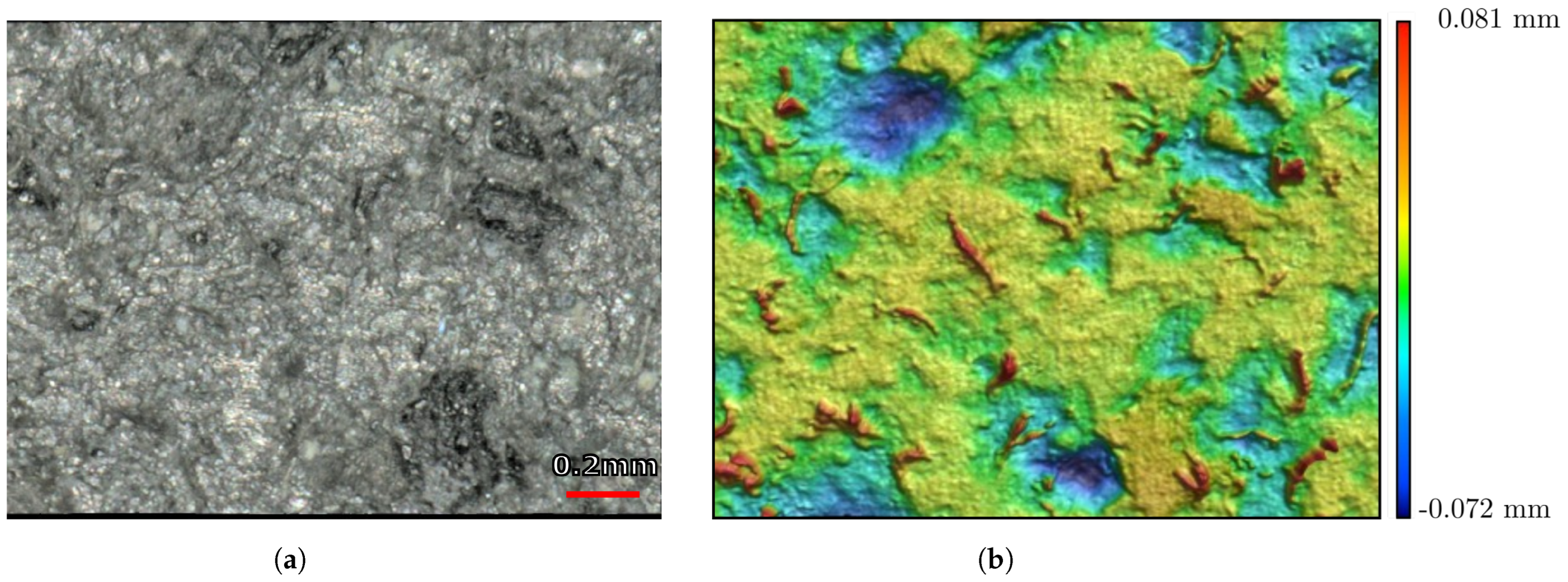
The pad’s surface is measured experimentally through a CLSM. Figure 4 shows an example of the measured topography over a scan area of 1.8 × 1.4 mm 2 with a resolution of 256 × 256 pixels. The measured topography (see Figure 4b) appears irregular and depicts characteristics of randomness. Hence, the random process theory, widely applied to analyze roughness, can be used to model accurately the probability function of the surface heights also known by the HDF. The latter holds only the out-of-plan information. To complete the characterization, the PSD is used to describe the spatial arrangement in the plane.
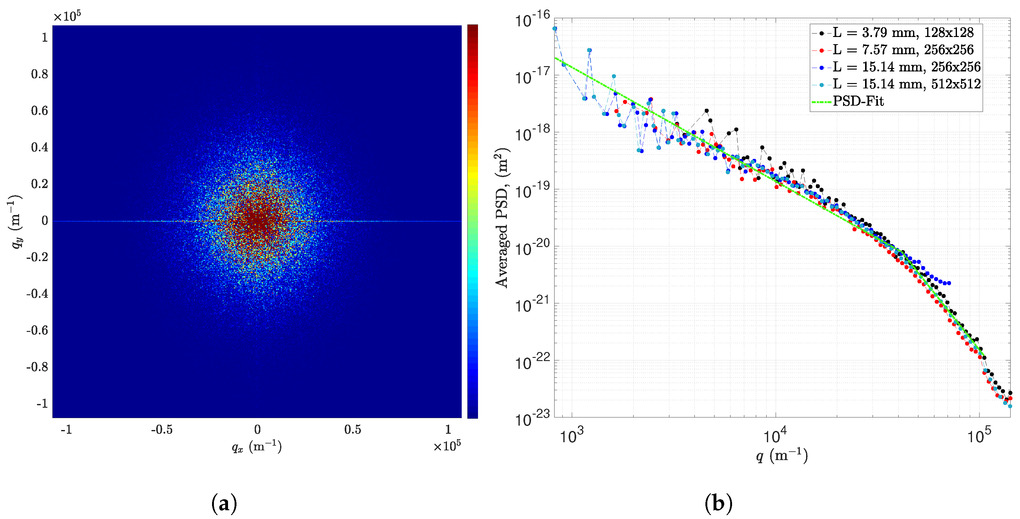
Figure 5a illustrates the computed 2D-PSD of the pad’s surface using the developments in our previous research work [18,38]. It shows clearly that the pad’s roughness is highly isotropic. Such a result allows computing the radial PSD (averaged) in order to study the effect of resolution and scan length. Moreover, it can be seen, in Figure 5b, that the behavior of the measured PSD is not sensitive to resolution or scan length. It conserves its shape despite the change of the measurement parameters. With regard to the PSD behavior, Figure 5b depicts roughly two linear regions in the log–log plot. It starts from the lower frequency, which is inversely correlated to the scan length q L = 2 π L , up to a high measured frequency, related to the short-distance cut-off wavevector, defined by q s = 2 π Δ where Δ refers to the sampling length. In fact, the radial PSD has a shape similar to the bi-fractal surfaces defined in [51]. The difference lies in the definition of the slopes of the linear regions. In fact, bi-fractal surfaces have a theoretical PSD form that can be defined as follows:
PSD ( q ) = C 0 q q L c 1 if q L < q < q c C 1 q q c c 2 if q c q < q s 0 else ,
where the exponents c i , i { 1 , 2 } (the slope of the linear regions in log–log plot) are related to the Hurst exponent H i as follows: c i = 2 ( H i + 1 ) with 0 < H i < 1 . In our case, the two regions have a slope of −2 and −4.5, which correspondents to Hurst exponents of H 1 = 0 and H 2 = 1.25 , respectively. The first region defines a borderline case of fractality, while the second is completely outside the fractal or the self-affine framework. However, the model defined in Equation (17) will be used to characterize the PSD of the pad’s surface. The parameters c 1 , c 2 , q L , q c , C 0 and C 1 are computed using a suitable optimization scheme on the radially averaged PSD exactly as defined in Equation (22) of [18].
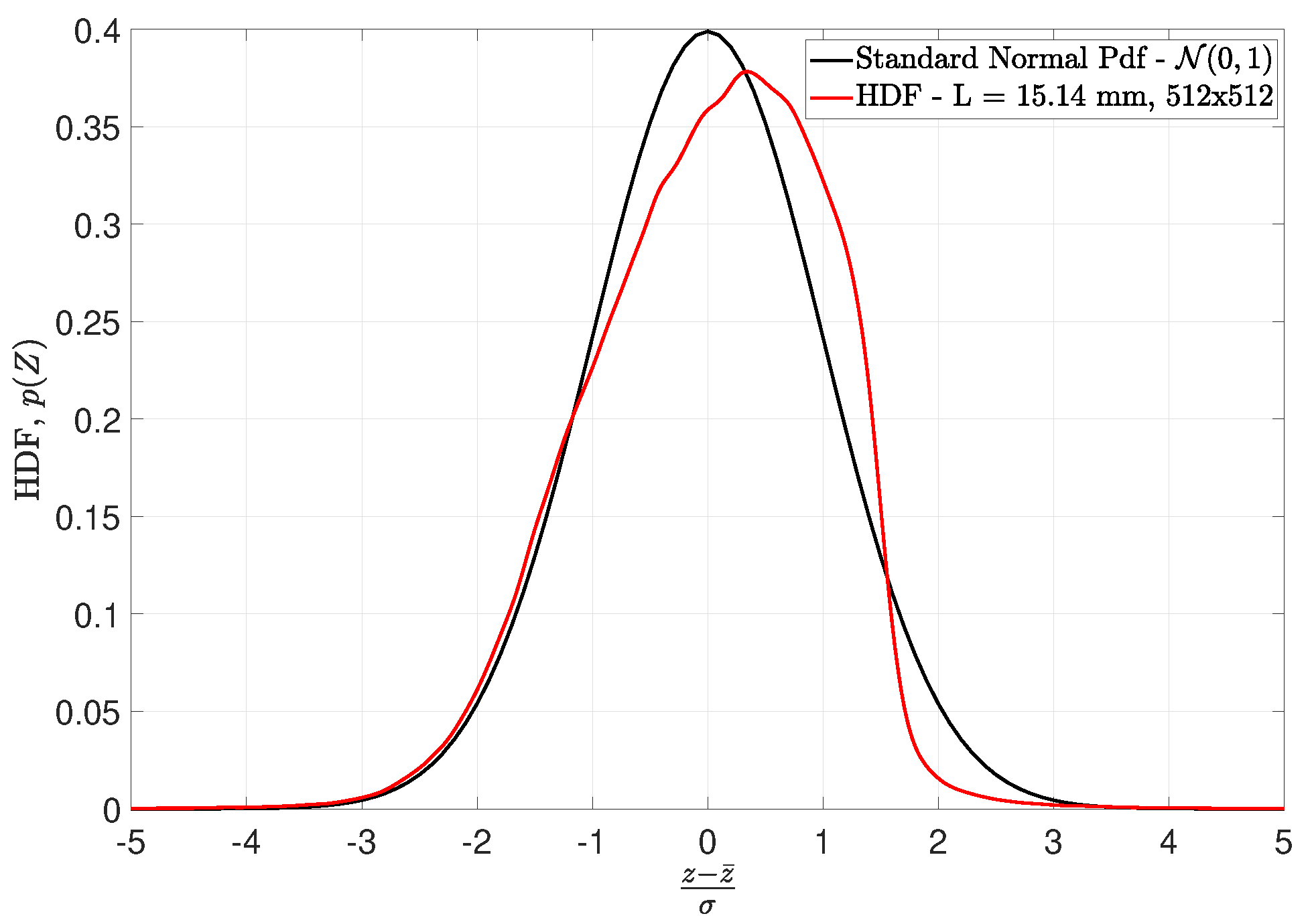
Figure 6 complements the information given by the PSD. It presents the HDF of the measured pad’s surface in a normalized manner and compares it with the centered and reduced normal law. As a first observation, one can see that the surface is approximately Gaussian. A notable difference is observed for the higher heights which makes the HDF asymmetric. This behavior was expected since automotive disc brake pads are usually compacted and ground to correct height. From Figure 6, the roughness of the pad can be defined by means of several parameters. For example, the mean (or median) plan z ¯ = 0.0256 mm, the root mean square (rms) roughness σ = 0.0331 mm, the skewness s = 0.2410 and the kurtosis κ = 3.6549 .
Note that in the following, the fitted PSD and HDF will be taken into account to numerically generate rough surfaces having the same spatial arrangement and roughness as that measured experimentally. The numerical procedure to generate artificial rough surface is inspired by Wu’s algorithm [52]. The latter is adapted to take into account PSDs with shapes similar to what has been defined in Equation (17).

3.2. Contact Law of Pad/Disc Interfaces

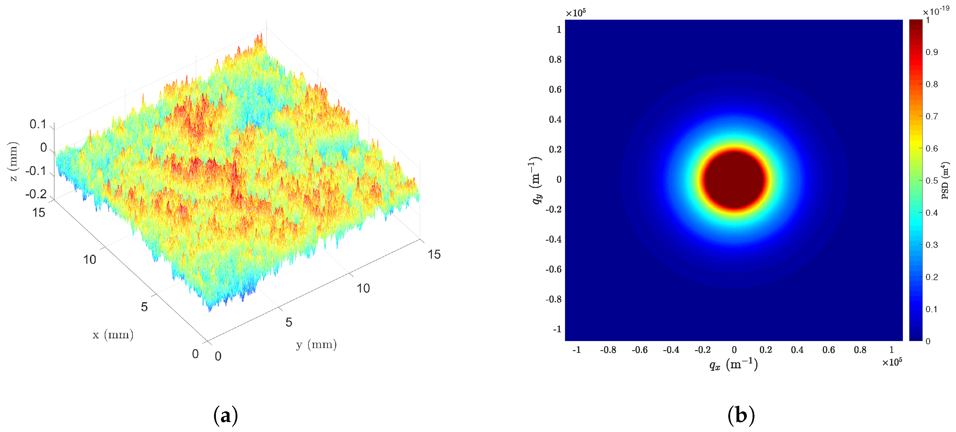
In the previous section, the surface of the pad has been fully described by two quantities: (i) PSD and (ii) HDF. These will act as an input data to artificially generate a batch of random rough surfaces. The artificial surfaces are intended to mimic the roughness behavior of the automotive disc brake pads so that they can be used to compute contact laws, i.e., load-separation curves. An example of an artificial rough surface is presented in Figure 7a. It has the same spectral and statistical specifications as the measured pad’s surface, namely (i) PSD properties (compare Figure 7b with Figure 5a) and (ii) the roughness parameters (the mean plan and the rms roughness).
After generating batch of artificial random surfaces, the next step is to compute the evolution of contact stresses against contact kinematics for each generated pad’s topography. At this stage, many models can be used. The study of the latter has been addressed in our previous research [38], where authors tried to explain the philosophy behind each theory with a comparative study. The concern here is to apply directly the result of [38] in order to solve frictionless rough contact and thus, obtain the evolution of contact stresses against the surface separation, commonly known as the gap. More precisely, BEM solver, introduced by Bemporad and Paggi [50], will be used to solve the contact problem between the artificial rough surfaces and the rigid surface of the disc. The choice of using BEM is motivated by the fact that it offers the best trade-off between FEM and semi-analytical models. Indeed, it is free of any kind of assumption unlike semi-analytical models, and it allows discretizing only the rough surface without the bulk, which can save considerably the CPU cost.
As explained above, the curve load-separation for each generated rough surface is obtained using BEM code developed in [50]. BEM simulation is performed on a generated rough surface of 2.825 × 2.825 mm 2 with a resolution of 128 pixels in both directions. This numerical setup is chosen because (i) BEM solvers show strong convergence on meshes containing at least 128 × 128 elements [38] and (ii) the single finite element (patch) of the pad’s surface has a averaged area equal to 2.825 × 2.825 mm 2 (see the element j defined in Figure 3c). Since the pad’s material involves an orthotropic behavior, only Young’s modulus, E z = 1983.3 MPa, in the most stressed direction, in this case the z-direction, and the Poisson’s ratio ν x z = 0.4054 are taken into account as inputs for BEM simulations. It should be noted that these micro-scale simulations assume a homogeneous and linearly elastic rough surface. Therefore, geometric (i.e., large deformations), material (i.e., plasticity) and contact interface non-linearities (i.e., adhesion and friction) are not considered in this computational framework.
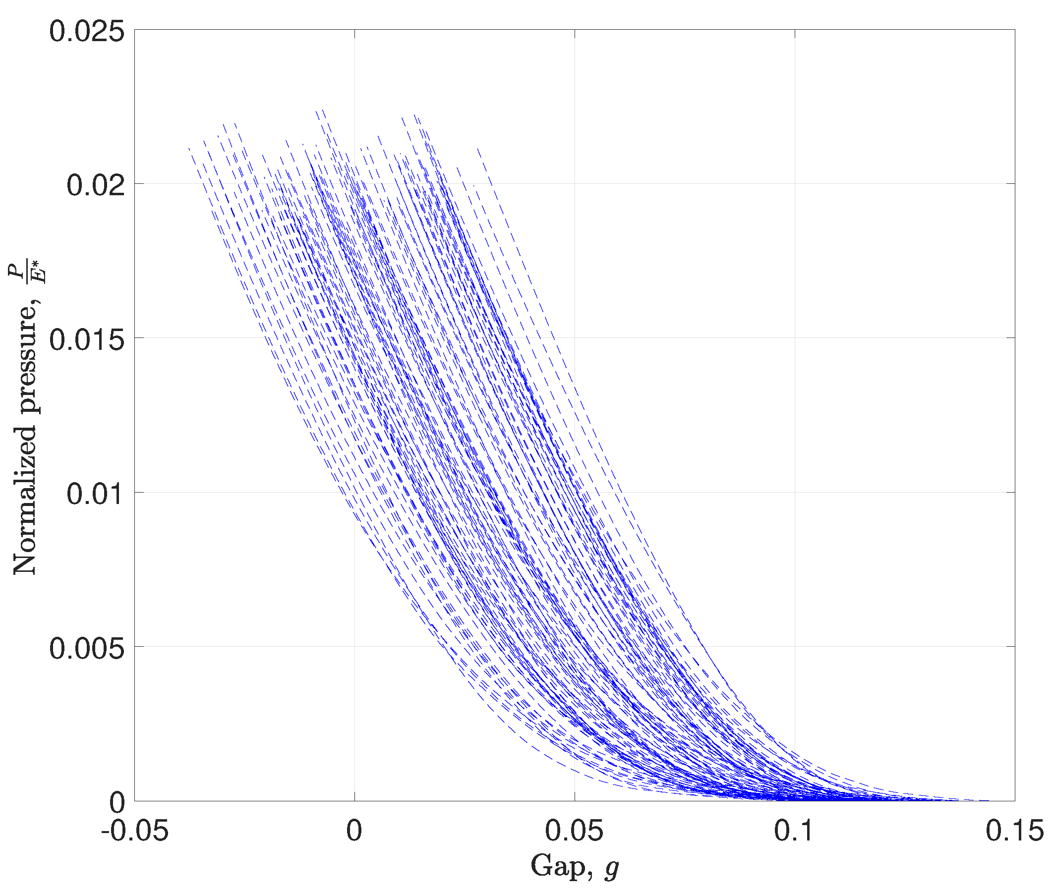
Figure 8 shows BEM results for 100 generated rough surfaces. It depicts the evolution of the normalized contact pressure, P E (where E is the composite modulus) versus the separation. The latter is defined as a distance between the imposed displacement of the rigid surface (i.e., the surface of the disc) and the median plan, z ¯ , of the rough surface. Each simulation, performed on a generated rough surface of 2.825 × 2.825 mm 2 , demonstrates a non-linear mechanical behavior of the considered set of asperities. For a small displacement, the separation between the two surfaces is large, which implies that only few asperities will be in contact, thus generating a low contact pressure. As long as the imposed displacement increases (synonymous to a decrease of the separation between the rigid surface and the midplane), the real contact area evolves, leading to an increase in contact pressure and, hence, the contact stiffness. This behavior, i.e., pressure-gap law, will be integrated into each patch (i.e., finite element) of the pad’s surface of the macroscopic FE model. Following this logic and according to the strategy defined in Figure 3, the macroscopic FE model of a disc brake system will have flat and smooth contact interfaces including the finite element patches. It should be noted that each patch will be driven by a contact law (BEM solution on single generated rough surface), instead of the classic penalty coefficient. Moreover, the gap of each patch is enriched by a threshold according to Equation (16). The new gap formulation will benefit from the HDF of Figure 6 to add a contribution (i.e., threshold) modeling the randomness of the measured height z. This enrichment is intended to ensure the activation of the contact elements in a non-uniform way just like what happens in surfaces with low-scale asperities.

3.3. Application to Dynamic Instabilities Prediction

The multi-scale approach is implemented to predict dynamic instabilities of a disc brake system model composed from three main structural subsystems (see Figure 3c): two pads and a rotating disc. The pad subsystem is broken down into three elements, namely the lining material, the backplate (lining support) and the shim that tends to reduce vibrations. The braking action is represented by a 5 bar pressure applied to the pads on a circular surface. This pressure replaces the action of the hydraulic system which tends to move the piston to squeeze pads against the rotating disc. The current FE model of the braking system has been used to conduct several numerical tests in our previous work [4,5].
The applied multi-scale analysis is divided into four major steps that are part of parallelized loop. After the pad’s topography characterization, the loop is started by:
1.
Artificial rough surface generation: The purpose of this step is to use the characterized HDF and PSD to generate a batch of artificial rough surfaces similar to the measured topography.
2.
Micro-scale contact simulations: Here, BEM solver introduced in [38,50] is used to solve the elastic contact problem considering artificial surface asperities and a rigid half-plane. The resolution is performed on the whole batch of the generated rough surfaces. Solving the micro-scale contact problem minimizes the convex quadratic program (QP) (see Equation (50) in [38]). The obtained results are the contact load (or the contact pressure) and the separation between the two contacting bodies.
3.
Enrichment of the contact element: The objective of the third step is to assign each micro-scale contact law (obtained in the second step) to each flat patch (i.e., contact element). Moreover, the gap between slave and master nodes of the macro-scale FE model (disc brake system FE model) is modified by adding a threshold to each gap in order to activate the contact elements in a non-uniform manner. As mentioned above, the added threshold depends closely on the measured HDF.
4.
Complex eigenvalues analysis: At this stage, the traditional CEA is performed. The beginning of the last step starts with a quasi-static analysis. Its goal is to solve, progressively as the load increases, the frictional contact using the enriched contact elements. At the end of this step, the well-known complex modal analysis is performed to compute both complex eigenvalues and eigenvectors and identify the unstable modes (those with negative damping). For more details, see Section 2.1 in [4].
In the studied example, 300 iterations are used to compute the dynamic instabilities of the braking system.
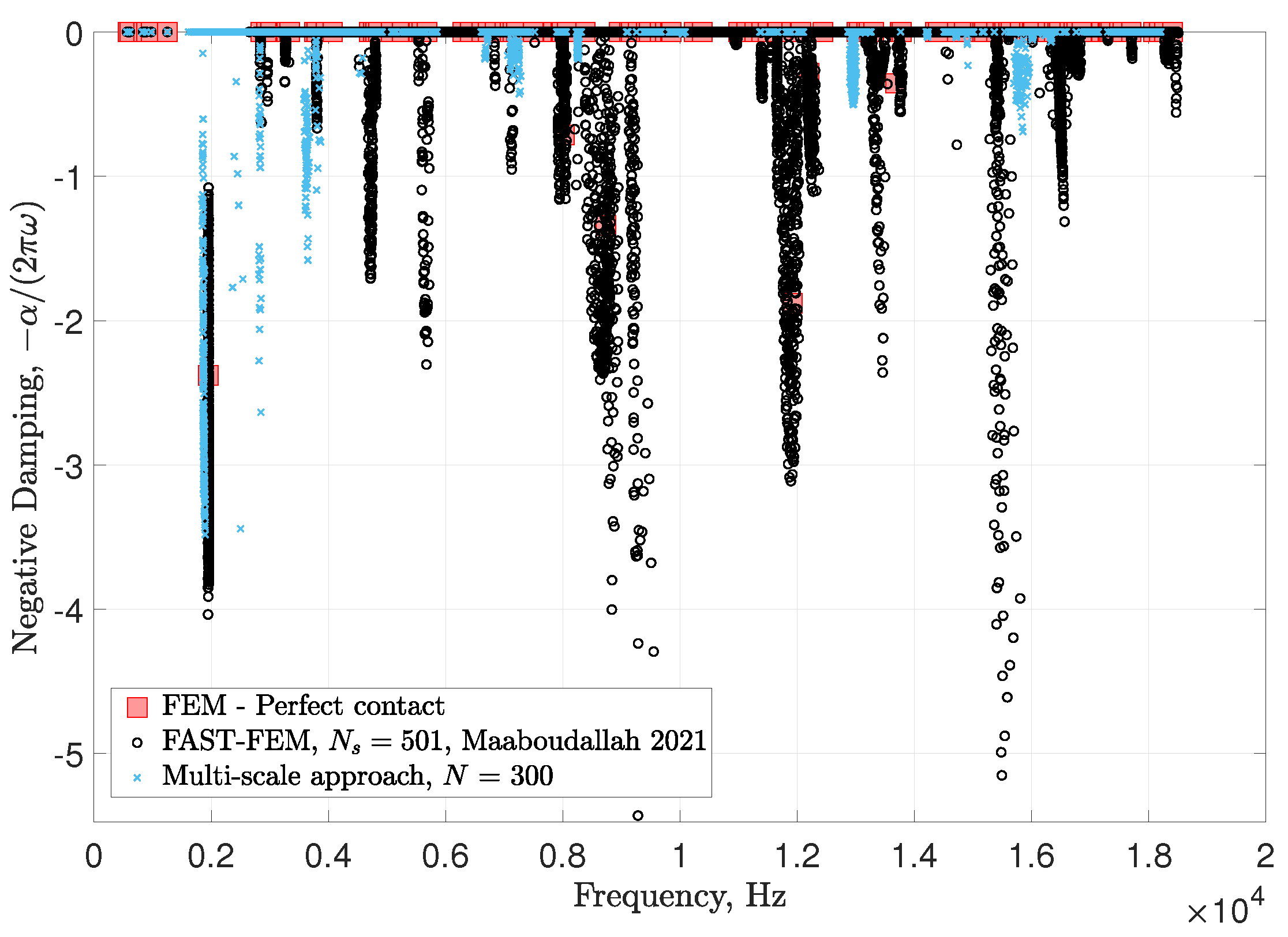
The result of the multi-scale approach is presented in Figure 9 (blue marker) where the negative damping, a ratio between the real and the imaginary part of the complex eigenvalues, is plotted as a function of the frequency. This figure shows only dynamic instabilities, which means unstable modes with a positive real part (i.e., negative damping below zero). In order to compare the robustness and limitations of the multi-scale approach, the result of FEM considering perfect contact with a pad/disc friction coefficient of 0.5 (red square marker) as well the results of a stochastic model based on a FAST-FEM solver (black marker) developed by Maaboudallah et al. [4] are added in the same figure. It is known [3,44] that stochastic modeling leads to better correlation with experimental data. At first sight, it can be seen that the introduced contact elements enrichment affects the dynamic instability predictions. In particular, the unstable modes predicted by FAST-FEM in the low frequency range are reproduced by the multi-scale approach. However, the latter fails to reproduce the instabilities predicted by FAST-FE or even by standard finite elements with perfect contact at high frequencies. Despite these observations, some unstable family modes around 13 and 15 kHz are roughly highlighted by the multi-scale approach. This unconventional behavior tends to demonstrate that the roughness affects mainly low frequencies. In other words, the addition of the roughness contribution, under the framework mentioned above, can be seen as a necessary but not sufficient condition. Indeed, a robust prediction of dynamic instabilities requires the integration of the roughness but also the randomness of the most sensitive variables like the friction coefficient of pad/disc interface and the normal Young’s modulus of the pad.

4. Conclusions

In this paper, we have presented a multi-scale computational method to predict friction-induced vibrations. The method uses micro-mechanic contact simulations on characterized rough surface to enrich the macro-scale finite element of a rubbing system. The idea behind the proposed approach lies in four essential points:
1.
Roughness characterization using the power spectral density function and the height distribution function;
2.
Micro-scale contact simulations on the characterization roughness using the boundary element method;
3.
Enrichment of the contact finite element using (i) the micro-scale contact laws (obtained from BEM) and (ii) the modified gap functions (obtained from HDF);
4.
Performing the complex eigenvalue analysis on the updated stiffness matrix.
The multi-scale method was applied to a scale model of a braking system. The results show that the proposed approach is more accurate than the classical one using a perfect contact law, based on a comparison with a stochastic model accounting for the uncertainties on several parameters such as friction. In addition, it is found that roughness has an effect on the predictions of dynamic instabilities. Indeed, taking into account the roughness brings out new unstable modes in the low frequencies. However, the effect of the integrated roughness is not clear in the high frequencies, since many stochastically predicted modes were not reproduced by the multi-scale strategy. Results of the investigation demonstrate that roughness is only one element among others that must be taken into account for a robust and accurate prediction of the dynamic instabilities. An uncertainty analysis must be conducted by varying the most important parameters including roughness to correctly model and predict the dynamic instabilities of frictional systems.

Author Contributions

Conceptualization, F.M.; methodology, F.M.; software, F.M. and N.A.; validation, F.M.; formal analysis, F.M.; investigation, F.M.; resources, N.A.; writing—original draft preparation, F.M.; writing—review and editing, F.M. and N.A.; visualization, F.M.; supervision, N.A.; project administration, F.M. and N.A. All authors have read and agreed to the published version of the manuscript.

Funding

This research received no external funding.

Acknowledgments

The authors acknowledge the financial support of Natural Sciences and Engineering Research Council of Canada (NSERC) and Fiat Chrysler Automobile Canada (FCA). This research was enabled in part by support provided by Compute Canada, Compute Quebec and SHARCNET. The first author would like to warmly thank Vladislav Yastrebov and Marco Paggi for their immense help and extremely relevant explanations during the workshops organized at Mines-Paristech France and IMT-Lucca Italy, respectively. This research work could not have been done without their help.

Conflicts of Interest

The authors declare no conflict of interest.

Abbreviations

The following abbreviations are used in this manuscript:
HDFheight distribution function
ACFautocorrelation function
PSDpower spectral density
FEMfinite element method
BEMboundary element method
GFMDGreen’s function molecular dynamics
RVErepresentative volume element
CEAcomplex eigenvalues analysis
N2SNode-to-Surface
CLSMconfocal laser scanning microscopy
RVrandom variable
RMSroot mean square
FASTFourier sensitivity amplitude test

References

  1. Sun, S.; Li, L.; Yue, Z.; Yang, W.; Zhao, Z.; Cao, R.; Li, S. Experimental and numerical investigation on fretting fatigue behavior of Nickel-based single crystal superalloy at high temperature. Mech. Mater. 2020, 150, 103595. [Google Scholar] [CrossRef]
  2. Yastrebov, V.A.; Durand, J.; Proudhon, H.; Cailletaud, G. Rough surface contact analysis by means of the Finite Element Method and of a new reduced model. Comptes Rendus Mécanique 2011, 339, 473–490. [Google Scholar] [CrossRef]
  3. Tison, T.; Heussaff, A.; Massa, F.; Turpin, I.; Nunes, R.F. Improvement in the predictivity of squeal simulations: Uncertainty and robustness. J. Sound Vib. 2014, 333, 3394–3412. [Google Scholar] [CrossRef]
  4. Maaboudallah, F.; Atalla, N. An efficient numerical strategy to predict the dynamic instabilities of a rubbing system: Application to an automobile disc brake system. Comput. Mech. 2021, 67, 1465–1483. [Google Scholar] [CrossRef]
  5. Maaboudallah, F.; Atalla, N. A “data-driven uncertainty” computational method to model and predict instabilities of a frictional system. Adv. Model. Simul. Eng. Sci. 2023, 10, 3. [Google Scholar] [CrossRef]
  6. Zhou, Q.; Luo, D.; Hua, D.; Ye, W.; Li, S.; Zou, Q.; Chen, Z.; Wang, H. Design and characterization of metallic glass/graphene multilayer with excellent nanowear properties. Friction 2022, 10, 1913–1926. [Google Scholar] [CrossRef]
  7. Ren, Y.; Huang, Z.; Wang, Y.; Zhou, Q.; Yang, T.; Li, Q.; Jia, Q.; Wang, H. Friction-induced rapid amorphization in a wear-resistant (CoCrNi)88Mo12 dual-phase medium-entropy alloy at cryogenic temperature. Compos. Part B Eng. 2023, 263, 110833. [Google Scholar] [CrossRef]
  8. Hetzler, H.; Willner, K. On the influence of contact tribology on brake squeal. Tribol. Int. 2012, 46, 237–246. [Google Scholar] [CrossRef]
  9. Greenwood, J.A.; Williamson, J.B.P.; Bowden, F.P. Contact of nominally flat surfaces. Proc. R. Soc. London. Ser. A Math. Phys. Sci. 1966, 295, 300–319. [Google Scholar] [CrossRef]
  10. Nayak, P.R. Random Process Model of Rough Surfaces. J. Lubr. Technol. 1971, 93, 398–407. [Google Scholar] [CrossRef]
  11. Abbott, E.J.; Firestone, F.A. Specifying Surface Quality—A Method Based on Accurate Measurement and Comparison. J. Mech. Eng. 1933, 55, 569–572. [Google Scholar]
  12. Bhushan, B. Solid Surface Characterization. In Introduction to Tribology; John Wiley & Sons, Ltd.: Hoboken, NJ, USA, 2013; Chapter 2; pp. 9–89. [Google Scholar] [CrossRef]
  13. Persson, B.N.J.; Albohr, O.; Tartaglino, U.; Volokitin, A.I.; Tosatti, E. On the nature of surface roughness with application to contact mechanics, sealing, rubber friction and adhesion. J. Phys. Condens. Matter 2004, 17, R1–R62. [Google Scholar] [CrossRef] [Green Version]
  14. Persson, B.N.J. Contact mechanics for randomly rough surfaces. Surf. Sci. Rep. 2006, 61, 201–227. [Google Scholar] [CrossRef] [Green Version]
  15. Majumdar, A.; Bhushan, B. Fractal Model of Elastic-Plastic Contact Between Rough Surfaces. J. Tribol. 1991, 113, 1–11. [Google Scholar] [CrossRef]
  16. Dodds, C.J.; Robson, J.D. The description of road surface roughness. J. Sound Vib. 1973, 31, 175–183. [Google Scholar] [CrossRef]
  17. Majumdar, A.; Tien, C.L. Fractal characterization and simulation of rough surfaces. Wear 1990, 136, 313–327. [Google Scholar] [CrossRef]
  18. Najah, M.; Maaboudallah, F.; Boucherit, M.; Ferguson, M.; Fréchette, L.; Charlebois, S.; Boone, F.; Ecoffey, S. Spectral analysis of the topography parameters for isotropic Gaussian rough surfaces applied to gold coating. Tribol. Int. 2022, 165, 107339. [Google Scholar] [CrossRef]
  19. Hertz, H. Ueber die Berührung fester elastischer Körper. J. Für Die Reine Und Angew. Math. 1882, 1882, 156–171. [Google Scholar] [CrossRef]
  20. Johnson, K.L. Contact Mechanics; Cambridge University Press: Cambridge, UK, 1985. [Google Scholar] [CrossRef]
  21. Archard, J.F.; Allibone, T.E. Elastic deformation and the laws of friction. Proc. R. Soc. London. Ser. A. Math. Phys. Sci. 1957, 243, 190–205. [Google Scholar] [CrossRef]
  22. Longuet-Higgins, M.S.; Deacon, G.E.R. Statistical properties of an isotropic random surface. Philos. Trans. R. Soc. London. Ser. Math. Phys. Sci. 1957, 250, 157–174. [Google Scholar] [CrossRef]
  23. Yastrebov, V.A.; Anciaux, G.; Molinari, J.F. The role of the roughness spectral breadth in elastic contact of rough surfaces. J. Mech. Phys. Solids 2017, 107, 469–493. [Google Scholar] [CrossRef] [Green Version]
  24. Ciavarella, M.; Delfine, V.; Demelio, G. A “re-vitalized” Greenwood and Williamson model of elastic contact between fractal surfaces. J. Mech. Phys. Solids 2006, 54, 2569–2591. [Google Scholar] [CrossRef]
  25. Ciavarella, M.; Greenwood, J.A.; Paggi, M. Inclusion of “interaction” in the Greenwood and Williamson contact theory. Wear 2008, 265, 729–734. [Google Scholar] [CrossRef]
  26. Paggi, M.; Ciavarella, M. The coefficient of proportionality κ between real contact area and load, with new asperity models. Wear 2010, 268, 1020–1029. [Google Scholar] [CrossRef]
  27. Zhang, S.; Song, H.; Sandfeld, S.; Liu, X.; Wei, Y.G. Discrete GreenwoodWilliamson Modeling of Rough Surface Contact Accounting for Three-Dimensional Sinusoidal Asperities and Asperity Interaction. J. Tribol. 2019, 141, 121401. [Google Scholar] [CrossRef]
  28. Afferrante, L.; Carbone, G.; Demelio, G. Interacting and coalescing Hertzian asperities: A new multiasperity contact model. Wear 2012, 278–279, 28–33. [Google Scholar] [CrossRef]
  29. Persson, B.N.J. Theory of rubber friction and contact mechanics. J. Chem. Phys. 2001, 115, 3840–3861. [Google Scholar] [CrossRef]
  30. Hyun, S.; Pei, L.; Molinari, J.F.; Robbins, M.O. Finite-element analysis of contact between elastic self-affine surfaces. Phys. Rev. E 2004, 70, 026117. [Google Scholar] [CrossRef] [Green Version]
  31. Yang, C.; Persson, B.N.J. Contact mechanics: Contact area and interfacial separation from small contact to full contact. J. Phys. Condens. Matter 2008, 20, 215214. [Google Scholar] [CrossRef] [Green Version]
  32. Yastrebov, V.A.; Anciaux, G.; Molinari, J.F. From infinitesimal to full contact between rough surfaces: Evolution of the contact area. Int. J. Solids Struct. 2015, 52, 83–102. [Google Scholar] [CrossRef]
  33. Polonsky, I.A.; Keer, L.M. A numerical method for solving rough contact problems based on the multi-level multi-summation and conjugate gradient techniques. Wear 1999, 231, 206–219. [Google Scholar] [CrossRef]
  34. Campañá, C.; Müser, M.H. Practical Green’s function approach to the simulation of elastic semi-infinite solids. Phys. Rev. B 2006, 74, 075420. [Google Scholar] [CrossRef]
  35. Campañá, C.; Müser, M.H. Contact mechanics of real vs. randomly rough surfaces: A Green’s function molecular dynamics study. Europhys. Lett. Assoc. 2007, 77, 38005. [Google Scholar] [CrossRef]
  36. Wriggers, P. Finite element algorithms for contact problems. Arch. Comput. Methods Eng. 1995, 2, 1–49. [Google Scholar] [CrossRef]
  37. Yastrebov, V.A. Numerical Methods in Contact Mechanics, 1st ed.; John Wiley & Sons, Ltd.: Hoboken, NJ, USA, 2013. [Google Scholar] [CrossRef]
  38. Maaboudallah, F.; Najah, M.; Atalla, N. A Review on the Contact Mechanics Modeling of Rough Surfaces in the Elastic Regime: Fundamentals, Theories, and Numerical Implementations; IntechOpen: Rijeka, Croatia, 2022; Chapter 5. [Google Scholar] [CrossRef]
  39. Wriggers, P.; Reinelt, J. Multi-scale approach for frictional contact of elastomers on rough rigid surfaces. Comput. Methods Appl. Mech. Eng. 2009, 198, 1996–2008. [Google Scholar] [CrossRef]
  40. Wriggers, P.; Nettingsmeier, J. Homogenization and Multi-Scale Approaches for Contact Problems. In Computational Contact Mechanics; Wriggers, P., Laursen, T.A., Eds.; CISM International Centre for Mechanical Sciences; Springer: Berlin/Heidelberg, Germany, 2007; pp. 129–161. [Google Scholar] [CrossRef]
  41. Waddad, Y.; Magnier, V.; Dufrénoy, P.; De Saxcé, G. A multiscale method for frictionless contact mechanics of rough surfaces. Tribol. Int. 2016, 96, 109–121. [Google Scholar] [CrossRef]
  42. Bonari, J.; Marulli, M.R.; Hagmeyer, N.; Mayr, M.; Popp, A.; Paggi, M. A multi-scale FEM-BEM formulation for contact mechanics between rough surfaces. Comput. Mech. 2020, 65, 731–749. [Google Scholar] [CrossRef] [Green Version]
  43. Paggi, M.; Reinoso, J. A variational approach with embedded roughness for adhesive contact problems. Mech. Adv. Mater. Struct. 2020, 27, 1731–1747. [Google Scholar] [CrossRef] [Green Version]
  44. Renault, A.; Massa, F.; Lallemand, B.; Tison, T. Experimental investigations for uncertainty quantification in brake squeal analysis. J. Sound Vib. 2016, 367, 37–55. [Google Scholar] [CrossRef]
  45. Fenton, G.A.; Griffiths, D. Random Field Generation and the Local Average Subdivision Method. In Probabilistic Methods in Geotechnical Engineering; Griffiths, D.V., Fenton, G.A., Eds.; CISM Courses and Lectures; Springer: Vienna, Austria, 2007; pp. 201–223. [Google Scholar]
  46. Li, C.C.; Der Kiureghian, A. Optimal Discretization of Random Fields. J. Eng. Mech. 1993, 119, 1136–1154. [Google Scholar] [CrossRef]
  47. Zhang, Z.; Oberst, S.; Lai, J.C.S. On the potential of uncertainty analysis for prediction of brake squeal propensity. J. Sound Vib. 2016, 377, 123–132. [Google Scholar] [CrossRef]
  48. Magnier, V.; Brunel, J.F.; Dufrénoy, P. Impact of contact stiffness heterogeneities on friction-induced vibration. Int. J. Solids Struct. 2014, 51, 1662–1669. [Google Scholar] [CrossRef]
  49. Maaboudallah, F.; Atalla, N. Beyond the main order sensitivity analysis for a frictional system: Is the eXtended FAST algorithm applicable? Nonlinear Dyn. 2022, 111, 5593–5614. [Google Scholar] [CrossRef]
  50. Bemporad, A.; Paggi, M. Optimization algorithms for the solution of the frictionless normal contact between rough surfaces. Int. J. Solids Struct. 2015, 69–70, 94–105. [Google Scholar] [CrossRef] [Green Version]
  51. Borri, C.; Paggi, M. Topology simulation and contact mechanics of bifractal rough surfaces. Proc. Inst. Mech. Eng. Part J J. Eng. Tribol. 2016, 230, 1345–1358. [Google Scholar] [CrossRef]
  52. Wu, J.J. Simulation of rough surfaces with FFT. Tribol. Int. 2000, 33, 47–58. [Google Scholar] [CrossRef]
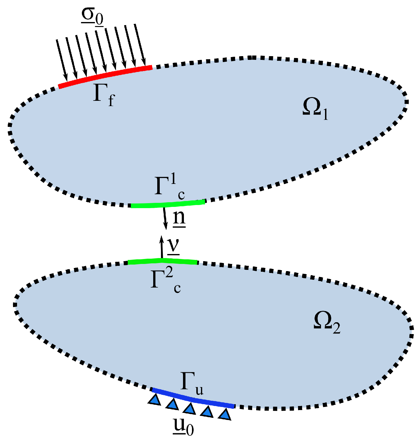
Figure 1. Contact between two deformable solids Ω 1 and Ω 2 . Ω 1 refers to the slave body and Ω 2 is the master one. The active contact interface is Γ c = Γ c 1 = Γ c 2 .
Lubricants 11 00344 g001
Figure 2. Construction of the contact finite element using Node-To-Surface (N2S) discretization. The contact element contains only one slave node attached to a master surface. The case presented in this figure contains n c = 5 contact elements.
Lubricants 11 00344 g002
Figure 3. The flowchart of the computational framework: (a) The first step aims to measure and then characterize the observed roughness. The functions deduced from the characterization, namely the height distribution function and the power spectral density function, will be used in the second step (b) to numerically generate rough surfaces similar to what has been measured. In this step (b), BEM solver is used to solve the low-scale contact problem. The results of the BEM and the characterization will enrich the contact laws and the separation between master and slave surfaces. In the third step (c), the friction-induced vibrations of an automotive disc brake system are predicted.
Lubricants 11 00344 g003
Figure 4. Confocal (a) scan and (b) measurements on the surface of a disc braking system pad.
Lubricants 11 00344 g004
Figure 5. Power spectral density functions (PSD) of the pad’s rough surface: (a) 2D-PSD of the 15 × 15 mm 2 with a resolution of 512 × 512 pixels. (b) The effect of scan length and resolution on the averaged 2D-PSD.
Lubricants 11 00344 g005
Figure 6. Comparison between the normalized height distribution function (HDF) of the pad’s rough surface (red curve) and the standard Gaussian distribution (back curve).
Lubricants 11 00344 g006
Figure 7. 3D view of the artificial rough surface generated with a resolution of 512 pixels in both directions (on the left—(a)) and its 2D-PSD (on the right—(b)).
Lubricants 11 00344 g007
Figure 8. Evolution of the normalized contact pressure, P E , as a function of the gap, g for 100 generated rough surfaces. The contact pressure is defined as P = F L 2 , where F denotes the contact load and L 2 refers to the finite element path. The gap or the surface separation is defined as a distance between the rotating disc (rigid flat surface) and the median rough surface, z ¯ .
Lubricants 11 00344 g008
Figure 9. Prediction of dynamic instabilities: comparison between (i) the proposed multi-scale approach considering 300 iterations, (ii) FAST-FEM solver [4] and (iii) the traditional FEM using perfect contact.
Lubricants 11 00344 g009
Disclaimer/Publisher’s Note: The statements, opinions and data contained in all publications are solely those of the individual author(s) and contributor(s) and not of MDPI and/or the editor(s). MDPI and/or the editor(s) disclaim responsibility for any injury to people or property resulting from any ideas, methods, instructions or products referred to in the content.