Article

Comparative Micro-Scale Abrasive Wear Testing of Thermally Sprayed and Hard Chromium Coatings

by
Georgiana Chișiu
1,
Roxana-Alexandra Gheța
2,
Alina-Maria Stoica
1 and
Nicolae-Alexandru Stoica
1,*
1
Faculty of Mechanical Engineering and Mechatronics, University Politehnica of Bucharest, 313 Splaiul Independentei, 060042 Bucharest, Romania
2
Segula Technologies Romania SRL, 010101 Bucharest, Romania
*
Author to whom correspondence should be addressed.
Lubricants 2023, 11(8), 350; https://doi.org/10.3390/lubricants11080350
Submission received: 25 July 2023 / Revised: 10 August 2023 / Accepted: 15 August 2023 / Published: 17 August 2023
(This article belongs to the Special Issue Friction and Wear of Alloys)

Abstract

:
Nowadays, due to the carcinogenic effects of chrome, replacing the hard chromium used for hydraulic components like rods and cylinders is becoming increasingly requested. Thermally sprayed coatings are a solution to the problem; however, proper understanding and characterisation of their tribological behaviour are essential for the successful exploitation of surface engineering. Thus, the main aim of this study is to evaluate the abrasive wear characteristics of two metal sprayed layers, tungsten carbide (WC) deposited through the high-velocity oxygen fuel coating (HVOF) method and Fe alloy coating deposited through thermal spraying with an electric arc with a wire-electrode G3Si1, and compare the results with those of an electrochemically deposited hard chromium layer. Their wear resistance is then related to their hardness. The results highlight the tribological performances of the thermally sprayed coatings. The HVOF WC10Co4Cr coating has a wear coefficient and a material wear volume that are hundreds of times lower than those of the other two coatings.

1. Introduction

Under the current conditions of modern industrial production, based on optimisation, efficiency, and cost-effectiveness, machines, equipment, and installations must be operated at optimum levels without accidental failure or disruptions. By default, all of these contribute, in essence, to the superior quality of the finished products. Machines, equipment, and installations are subjected to wear during operation, which may also cause part processing errors, increased consumption, and even work accidents. Extending the service life can be achieved by slowing down the physical wear of the component parts. According to the manufacturer’s prescriptions, this is ensured by operation of the machines at normal load (by avoiding overloads), continuous observation of their condition and functionality, proper maintenance, lubrication of moving parts, good quality repairs, and their timely intervention [1,2,3,4,5].
Reconditioning is recognised as a technology to treat worn parts, ensuring reliability. This is an unlimited subject in terms of the technology, installations, and materials used [2,3,4,6,7]. Wear is any loss of material on solid friction surfaces resulting in a change in dimensions, geometric shape, and clearances. This is a complex phenomenon, determined by many factors and conditions (mechanical properties, geometric features of the surfaces, operating parameters, lubrication quality, lubricants used) [8,9]. After a certain number of hours of operation of an assembly, some parts have an advanced wear condition. This makes it impossible to continue the operation of the assembly in question. In addition to wear, after a long period of running time, a machine or machine parts may be out of service due to accidental causes impacts such as overloads, misfitting, material defects, etc. [2,10,11].
Reconditioning by thermal spraying can be one of the most effective means of protecting surfaces from wear or corrosion. Restoring the dimensions of the parts, maintaining the precise clearances, and improving the physico-chemical, mechanical, and technological characteristics of the surface layer increase the service life and reduce costs [10,12,13,14]. The flame spraying metallisation consists of melting the filler material (powders, wire, and bars) into a gas-oxy flame that burns in the free atmosphere and spraying melted metal droplets onto the surface of the metallised piece [2].
In the case of high-velocity oxygen fuel (HVOF) spraying, combustion takes place in a confined space. The flame comes out of the combustion chamber through a laval profile nozzle, which ensures the spray jet convergence, and a jet speed of 1500–2000 m/s is reached. The powder is inserted perpendicular to the spray stream, and the metallizer body is intensely cooled with water. HVOF (high-velocity oxygen) is the most used technology for obtaining coatings [10,15,16,17].
Electric arc spraying metallisation technology consists of the melting of an electrode wire (adding material) by the electric arc forming between them and spraying melted drops with a jet of compressed air on the base material [2].
The factors influencing the hardness of the coating are the nature of the deposited material, the structure of the layer of deposited material, the porosity of the layer of deposited material, the thickness of the layer of deposited material, and the final processing of the layer of deposited material [2,10]. The hardness of the thermally sprayed material layer increases with the increase in the impact velocity of the particles sprayed on the material surface, the decrease in granulation, the decrease in the proportion of oxides contained in the deposited layer, and the increase in the thickness of the deposited layer. This hardness decreases with the decrease in the spraying pressure, the increase in the spray distance, the increase in the layer temperature after metallisation, and the increase in the feed speed or flow of the build-up material [2,3,10,18,19,20].
Wear resistance generally increases with metallisation and is even better than the wear resistance of the original part. This is due both to the fact that the structure of the sprayed layers is a characteristic of heat treatment, the layers have a high hardness, and the structure of the sprayed layers is characterised by the existence of pores. Consequently, all surfaces subjected to friction wear should be treated by thermal spraying even before their first use, not just when they are reconditioned after the first cycle of operation. This would extend the work life of the parts [2,10,16,21,22,23].
Wear is a tribological process that is manifested by the destruction of the surface layer of a solid body in contact with another solid body or a fluid medium with suspended solid particles. If there is relative movement between the two bodies, then friction occurs, and wear is called frictional wear. Degradation of surfaces is manifested by the loss of material and changes in size and geometric shape [8,24,25,26].
Many surface engineering applications require increased wear resistance, as is the case with hydraulic rods or cylinders. Adequate understanding and characterisation of tribological behaviour are essential for the successful exploitation of surface engineering.
Hydraulic rods and cylinders are commonly coated with electrodeposited hard chromium. An alternative to this coating technique is thermal spraying. For the research presented in this paper, in the case of a hydraulic cylinder, electrical arc-spraying metallisation with two electrode wires was selected as the coating process. The two electrode wires advance through a drive system using a small air rotor. The electrode wires are elastically deformed and directed toward each other to short-circuit and form an electric arc by two copper pads at a temperature of approximately 4000 °C. The electrical contacts shall be made at the same time, both directly on the electrode wires and on copper pads. Compressed air or inert gas coming out of the nozzle sprays material from the tip of the electrode wires, which melts in the electric arc and forms, together with the sprayed droplets, the spray jet normally oriented on the surface of the workpiece.
Tribological tests regarding abrasive wear are usually carried out in the presence of an abrasive suspension, like silicon carbide (SiC). Abrasive wear manifests in the form of traces of microchipping (scratches) on both surfaces in contact. It is specific to the active components of the machines that work in abrasive environments and to friction couplings that are poorly protected (piston-cylinder). Abrasion resistance is usually assessed using wear tests, in which mass losses or dimensional changes are monitored. The most known tribological application is a micro-scale ball abrasion test, and tribometers based on this method are available on the market. Based on the ball micro-abrasion method, a practical and simple tool has been developed to quickly measure the wear properties of thin coatings in a single test [9,24].
Taking all these factors into consideration, in recent years researchers have studied HVOF WC coatings to determine their mechanical properties and wear behaviour. Similar to our study, Castro et al. [17] compared the microstructure, roughness, hardness, and wear resistance of a WC-10Co4Cr-HVOF coating with those of hard chrome, which are used in hydraulic cylinders. To determine the wear characteristics of the coatings, they employed two different methods: the rubber and sand wheel wear test and the pin-on-disc wear test. Their results indicated superior properties for the WC-CoCr HVOF-coated steel. Bolelli et al. [23] studied the abrasive wear behaviour of WC–10Co4Cr hardmetal coatings sprayed onto carbon steel substrates using two HVOF and two HVAF spray processes. They performed rotating ball-on-disk tests and a modified version of the dry sand–rubber-wheel abrasion wear test, showing that coatings deposited from coarse feedstock powders suffer higher wear losses than those obtained from fine powders. In another study, Samodurova et al. [27] analysed the properties of a WC–10%Co–4%Cr detonation spray coating deposited on the Al–4%Cu–1%Mg Alloy. The micro-hardness values they obtained for the carbide coating (1300–1350 HV0.3) are significantly higher in comparison with tungsten carbide coatings sprayed by various methods on aluminium alloy substrates. Ksiazek et al. [28] studied the wear properties of HVOF-sprayed composite coatings (WC–Co + Cr) on ductile cast iron using abrasion resistance testing in an abrasive suspension and demonstrated that the composite coating has better (by almost 22%) resistance to abrasion than the cast iron. Wu et al. [29] performed wear tests with abrasive particles on three HVOF coatings (Ni60, WC10Co4Cr, and 316L) on a self-made NM-200 rubber wheel testing machine, and their results indicated that the WC10Co4Cr coating has the best wear resistance.
In view of the above, the main aim of the experimental work presented in this paper is to determine the abrasive wear resistance of some samples coated by thermal spraying and compare the results with those of a hard chromium coating. This is done by employing tests on a CSEM Calowear abrasion tester in the presence of a suspension of distilled water and SiC. Compared to the testing methods in other studies, this method not only allows the analysis of the wear resistance of the coatings, but also the determination of their thickness. Afterwards, the results are related to the hardness of the layers.

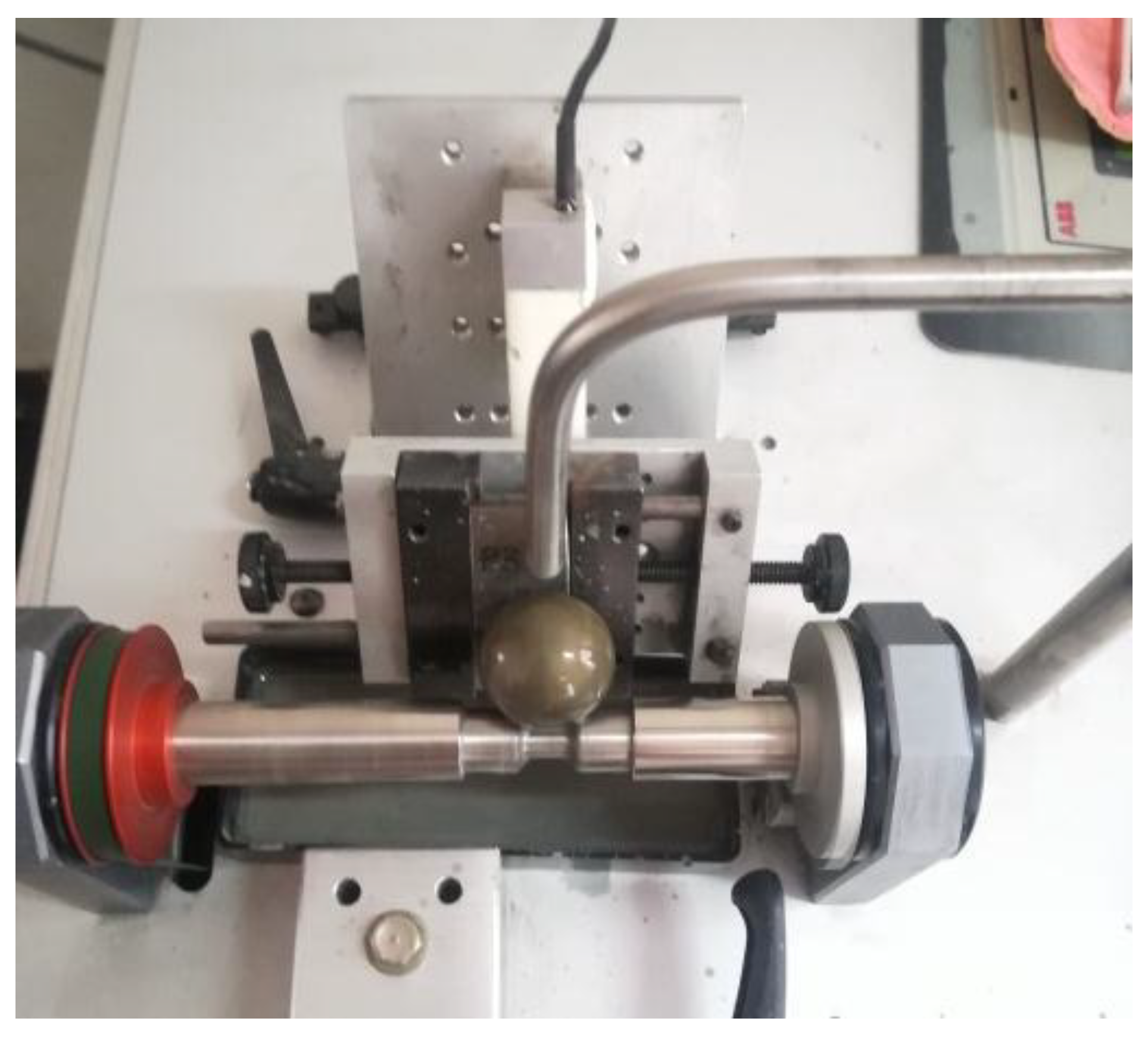
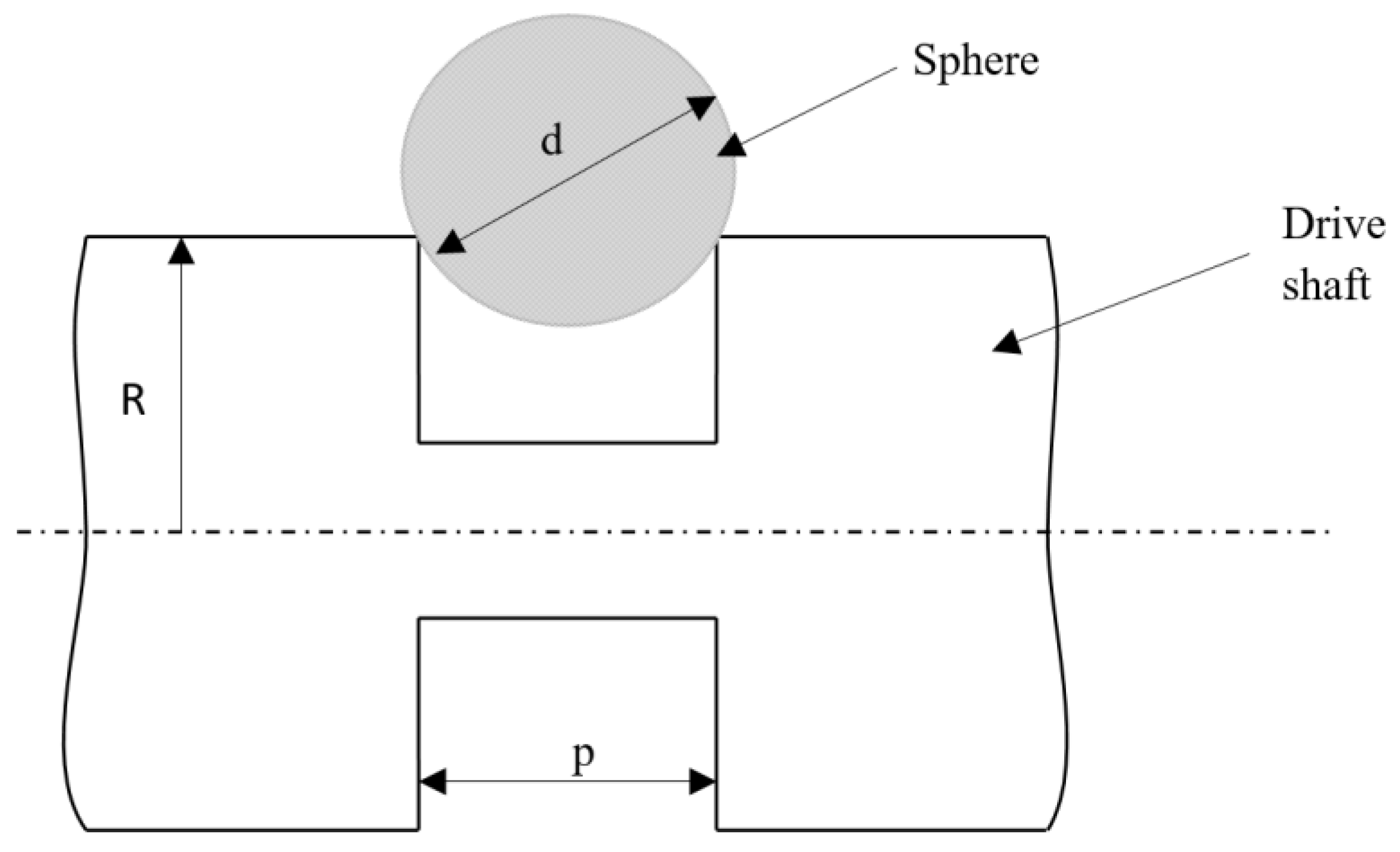
2. Materials and Methods

To determine the abrasive wear resistance of thermally sprayed samples, experimental determinations were performed on a CSEM Calowear abrasion tester.
Figure 1 shows the diagram used to obtain the abrasion imprints that resulted after the micro-abrasion test.
For the comparative research, two test specimens with layers deposited by thermal spraying and, respectively, a specimen with a layer of hard chromium deposited electrochemically were used, as follows:
-
Specimen 1 (P1)—hard chromium layer deposited electrochemically;
-
Specimen 2 (P2)—alloy layer deposited by thermal spraying with an electric arc with electrode wire G3Si1;
-
Specimen 3 (P3)—tungsten carbide (WC10Co4Cr) layer deposited through HVOF (high-velocity oxygen fuel) thermal spraying.
The experimental samples were cut at 20 × 30 × 10 mm dimensions, and the thickness of the layers was between 0.15 and 0.2 mm. The average roughness for the 3 samples was between 0.22 and 0.31 µm. The materials tested for micro-abrasion were hard chromium, G3Si1, and WC. Table 1 summarizes the information on the 3 samples.
The surface of the samples has been honed to obtain the smallest roughness possible, and the values of the roughness are given in Table 2. The device used to measure the roughness of the surfaces was the SJ301 (Mitutoyo, Japan) profilometer.
The micro-abrasion tests were performed on the CSEM Calowear abrasion tester, using a metal ball with a diameter of 25.4 mm (Figure 2). The ball rolled on the surface of the coated sample, under its own weight, at a constant speed in the presence of a suspension of distilled water and SiC, which is fed at about 1 drop per second, with an average grain size of 3.5 μm and a concentration of 0.75 g/cm3. The ball rolled on the surface of the samples with a speed of 0.2 m/s.
For each sample, 3 tests were performed, each lasting 900 s. The normal force FN on the test sample has an average value of 0.48–0.6 N. The friction length (214,982 mm) that generated the wear was determined based on the diameter of the ball, the number of rotations made by it, and the characteristics of the contact between the ball and the drive shaft [26]. The recorded data is presented in Table 3.
The sliding length of the sphere that generates the wear is influenced by the diameter of the sphere and by the values of the elements from the contact between the sphere and the drive shaft (Figure 3) [26].
The sliding length can be calculated using Equation [8]:
L = π · R · n · d ( d 2 4 p 2 4 ) = 44.44 · n = 214,982 m m ,
where d is the sphere diameter (24.5 mm), L is the sliding length, n is the drive shaft number of revolutions (4842 rot), R is the drive shaft radius (6.5 mm), and p is the length of the contact between the sphere and the drive shaft (10 mm).
The wear volume of the material is calculated with the relation [8]:
V = π b 4 32 d , i f   b < < d
The wear coefficient can be calculated with the relation:
k = π · b 4 32 · L · F N · d ,
The thickness of the deposited layer is
h = x · y d ,
where x and y are measured by means of an optical microscope.
The wear imprints that resulted on samples P1, P2, and P3, respectively, after a 900 s cycle are shown in Figure 4.
The worn surface inspections of the surfaces of the test samples were carried out by optical microscopy according to SR EN 1321:2000, STAS 7626-79, CR 12361:1996 + AC: 1997 standards, with an Olympus GX51 optical microscope, with magnification powers ranging from 50× to 1000×. This optical microscope is equipped with specialised image processing software, AnalySis.

3. Results

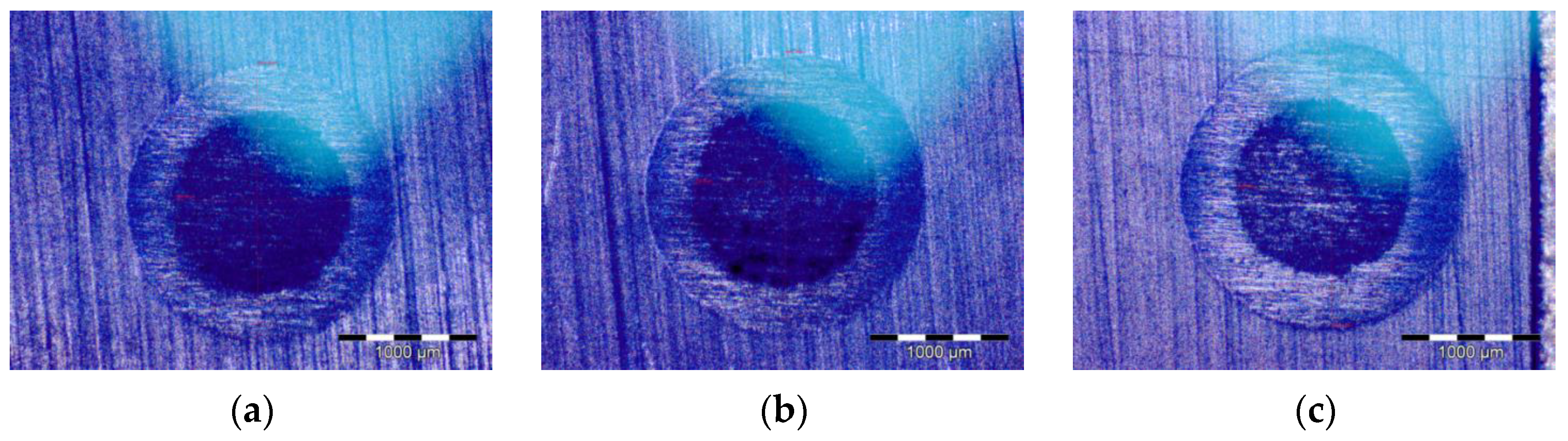
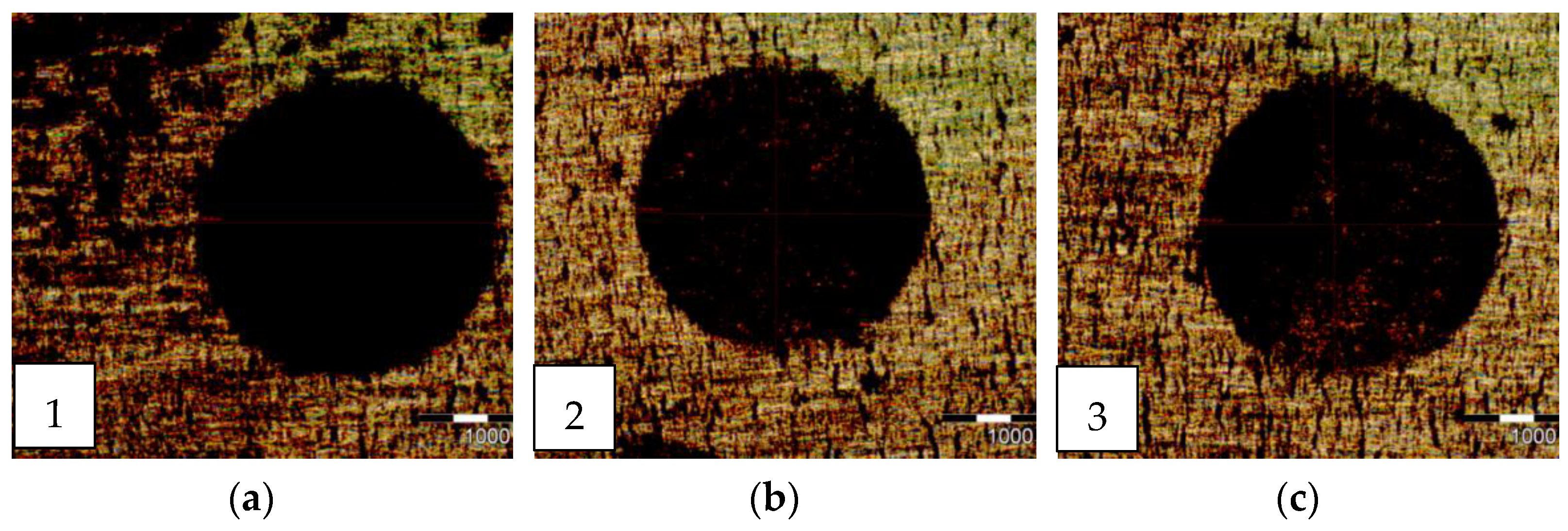
3.1. Optical Analysis of the Wear Imprints

Figure 5, Figure 6 and Figure 7 present the images of the imprints obtained on the surface of the samples taken under the optical microscope. The measured values of the diameters of the imprints on the sample surface are found in Table 4, Table 5 and Table 6. In the case of the hard chromium-coated sample (P1), after the 900 s wear test, the substrate is reached. This is visible from the wear imprint, which has two diameters. The steel substrate can be seen inside the internal diameter, while between the two diameters is the wear track for the hard chromium coating.
In the case of the other two samples, P2 and P3, the substrate was not reached at the end of the abrasive wear tests due to the thickness of the coating. Sample P2, which has a coating deposited by thermal spraying with an electric arc with electrode wire G3Si1, has a smaller wear imprint than sample P1. Sample P3, which has a tungsten carbide (WC) coating deposited through HVOF thermal spraying, has the smallest wear imprint, indicating that it has better wear performance than the other two coatings.

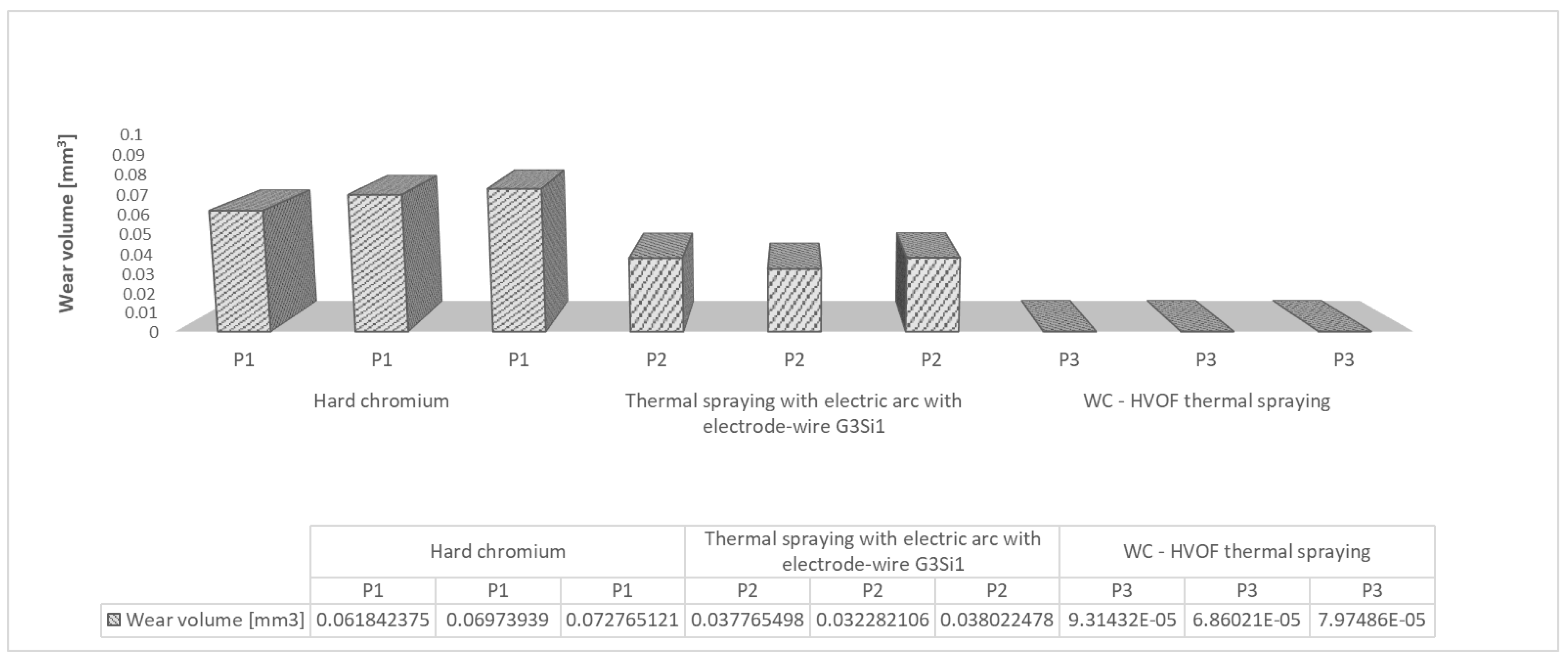
3.2. Wear Coefficient and Wear Volume
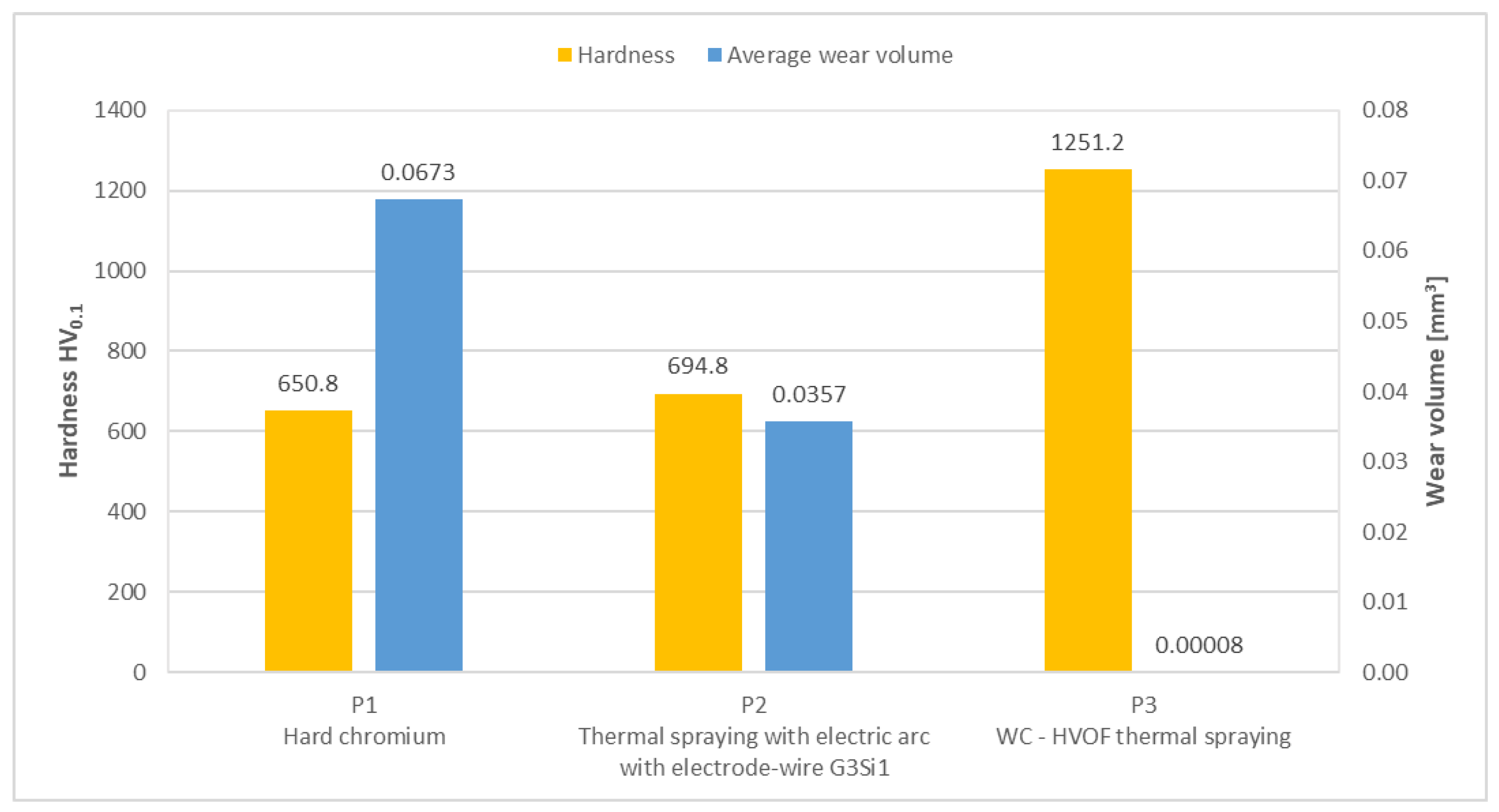
Table 7, Table 8 and Table 9 show the results obtained based on the determination of the mean diameter of the wear imprint and the application of the algorithm described in Section 2 of the paper. The results presented in Table 7, Table 8 and Table 9 are the calculated sliding length (L), mean diameter of the wear imprint (b) measured with the optical microscope, load force (FN) registered by the CSEM Calowear abrasion tester, calculated wear coefficient (k), and wear volume (V), as well as the average value of these parameters. Our results are in good agreement with those obtained by other researchers [17,23,29,30].
Compared to hard chromium, thermal spraying with an electric arc with electrode wire G3Si1 has improved wear performance (wear coefficient and wear volume are reduced by half). However, by far the best results were obtained for the tungsten carbide HVOF thermally sprayed coating. Its wear coefficient and wear volume are hundreds of times lower than those of the other two coatings. An in-depth analysis is presented in the Discussion section.

3.3. Micro-Hardness

To determine the micro-hardness of the layers of the three samples, five determinations were made for each deposited layer with a test force of 0.98 N (HV0.1) and a 5 s loading time. In-line measurements were performed, with distances between indentations of at least 500 μm. The results of these determinations are presented in Table 10, where the average value was calculated for each sample. The values are similar to those obtained by other researchers [17,23,27,29,30,31].
The hardness values measured on the surfaces of the samples coated with tungsten carbide are clearly superior to the values measured on the surfaces of the samples coated with hard chromium.

4. Discussion

4.1. Optical Analysis of the Wear Imprints

The external diameters of the wear imprints obtained on the surface of the samples after the abrasive wear tests were measured with the help of the AnalySis processing software of the optical microscope. Three wear tests were performed on each sample, and based on the measured external diameters, an average value of the diameter was calculated. For the P1 hard chromium sample, the calculated average external diameter was 2049.60 μm. For the P2 sample, which has a coating deposited by thermal spraying with an electric arc with electrode wire G3Si1, the average external diameter was lower than that of P1, with a value of 1746.47 μm. Sample P3, which has a tungsten carbide (WC) coating deposited through HVOF thermal spraying, had the smallest wear imprint, having an average external diameter of 379.67 μm. This is 5.4 times smaller than that of sample P1 and 4.6 times smaller than that of sample P2. This is the first obvious indication that the tungsten carbide (WC) layer deposited through HVOF thermal spraying has better wear performance than the other two coatings.

4.2. Wear Coefficient and Wear Volume

Figure 8 presents a comparative analysis of the resulting material wear volume, while Figure 9 compares the values of the wear coefficient of the three coatings, calculated based on the diameters of the three wear imprints for each of the three samples.
The hard chromium layer deposited electrochemically (sample P1) has an average wear coefficient of 6.58 × 10⁻⁷ mm3/Nm and a wear volume of 6811 × 10−5 mm3. On the other hand, the alloy layer deposited by thermal spraying with an electric arc with electrode wire G3Si1 (sample P2) has an average wear coefficient of 2.78 × 10⁻⁷ mm3/Nm, which is 2.37 times lower than that of the hard chromium layer. The average wear volume of sample P2 is 3602 × 10−5 mm3, 1.89 times lower than that of sample P1. This indicates that thermal spraying with an electric arc with electrode wire G3Si1 has improved wear performance compared to electrochemically deposited hard chromium. The highlighted results are those of the tungsten carbide layer deposited through HVOF thermal spraying. This type of coating outperforms the other two by hundreds of times in terms of wear resistance. Sample P3 has an average wear coefficient of 6.83 × 10⁻¹⁰ mm3/Nm (958 times lower than P1 and 405 times lower than P2) and a wear volume of 8.05 × 10⁻⁵ mm3 (846 times lower than P1 and 448 times lower than P2).
Analysing the charts shown in Figure 8 and Figure 9, it can be clearly seen that the thermally sprayed layers have a better wear resistance compared to hard chromium, but the wear volume and wear coefficient results for the tungsten carbide HVOF thermally sprayed coating (P3) stand out.

4.3. Micro-Hardness

The micro-hardness (HV0.1) of the layers of the three samples was determined at five separate points on their surface, and afterwards, the average value was calculated. To correlate the wear resistance of the coatings with their hardness, these values are presented in Figure 10, showing the interrelationship between the two characteristics.
For the hard chromium coating, the determined hardness is uniform and has an average determined value of 650.8 HV0.1. Slightly better results were obtained for the thermally sprayed G3Si1 layer, which has an average hardness of 694.8 HV0.1. As can be seen from the graph in Figure 10, the micro-hardness values measured on the surface of the tungsten carbide HVOF thermally sprayed layer are clearly higher than those determined on the hard chromium layer, with the average value being 1251.2 HV0.1.
An observation can be made regarding tungsten carbide: it is very hard, but when melted, it reacts with O2; oxides can form in this way, and the hardness can decrease.
Overlapping the results obtained for the wear volume and the values of the micro-hardness obtained in [25], it can be concluded that the wear resistance is directly related to the hardness of the coating. A higher hardness leads to a lower wear volume, which is obvious for the tungsten carbide HVOF thermally sprayed coating. Its hardness is almost twice as high as that of the other two coatings, leading to a wear volume that is hundreds of times smaller.

5. Conclusions

In this paper, the abrasive wear resistance of some samples coated by thermal spraying and hard chromium was compared. Also, correlations between the hardness of the coating and the abrasion resistance were established.
The coatings were investigated for their abrasion resistance and hardness. The results obtained show a correlation between the hardness of the coating and its abrasion resistance.
Regarding the wear coefficient and the wear volume, the following can be concluded:
-
P1—The hard chromium layer wears much faster than the layers deposited by thermal spraying, with the substrate of the sample being visible after the 900 s cycle.
-
P2—The Fe-based alloy layer deposited by electric arc thermal spraying has a much lower wear resistance than tungsten carbide, which can be explained by the lower hardness, the stresses accumulated on the worn surface, and the surface quality after mechanical processing.
-
P3—The tungsten carbide layer deposited by the HVOF process has the best wear resistance due to the surface hardness of over 1200 HV0.1.
From the point of view of the correspondence between the technological process and the properties of the layers, it results that:
-
To obtain layers with very high hardness, as required by applications such as hydraulic cylinders, it is recommended to use powdered materials in the HVOF process.
-
The advantage of higher porosity, however, is that it contributes decisively to increasing wear resistance. This is explained by the fact that pores form in the accumulators of the lubricant and contribute to the increase in resistance to crushing of the film of lubricant between the two surfaces in contact. Thus, remarkable anti-friction properties are obtained.
-
On the other hand, as in the case of sample P2, the wear resistance is affected by the porosity of the layers (approx. 10%). This can affect the coating. In addition, the pores can form microcracks, which lead to the detachment of micro-particles from the thermally sprayed layer.

Author Contributions

Conceptualisation, G.C. and R.-A.G.; methodology, G.C., R.-A.G. and N.-A.S.; software, A.-M.S.; validation, G.C., A.-M.S. and N.-A.S.; formal analysis, G.C. and N.-A.S.; investigation, G.C., A.-M.S. and N.-A.S.; writing—original draft preparation, G.C.; writing—review and editing, A.-M.S. and N.-A.S. All authors have read and agreed to the published version of the manuscript.

Funding

This research received no external funding.

Data Availability Statement

The data presented in this study are available on request from the corresponding author.

Conflicts of Interest

The authors declare no conflict of interest.

References

  1. Dumitru, G.M. Rehabilitation of Machinery and Equipment (Reabilitarea Mașinilor și Utilajelor); Bren: Bucharest, Romania, 2004. [Google Scholar]
  2. Dumitru, G.M.; Radu, C.; Dumitru, B. Reconditioning and Repairing Products (Recondiționarea și Repararea Produselor); Printech: Bucharest, Romania, 2010. [Google Scholar]
  3. Radut, M.; Coman, P.; Siteanu, E. Reconditioning Parts (Recondiționarea Pieselor); Militara: Bucharest, Romania, 1983. [Google Scholar]
  4. Huzum, N.; Rantz, G. Technological Processes, Maintenance and Repair of Machinery and Equipment (Procese Tehnologice, Intretinerea si Repararea Masinilor si Utilajelor); Didactica si Pedagogica: Bucharest, Romania, 1997. [Google Scholar]
  5. Benea, L.; Wenger, F.; Ponthiaux, P.; Celis, J.P. Improved hardness and tribocorrosion properties of nickel coatings by Co-depositing ZrO2 micro-sized dispersed phase during electroplating process. Ann. “Dunarea Jos" Univ. Galati Fascicle IX 2006, 29, 17–26. [Google Scholar]
  6. Rădoi, M.; Huzum, N.; Rantz, G.; Baciu, E.; Crivac, G.; Dinicica, C.; Dragomir, I. Reconditioning Parts (Reconditionarea Pieselor); Tehnica: Bucharest, Romania, 1986. [Google Scholar]
  7. Thompson, J.A.; Clyne, T.W. The effect of heat treatment on the stiffness of zirconia top coats in plasma-sprayed TBCs. Acta Mater. 2001, 49, 1565–1575. [Google Scholar] [CrossRef]
  8. Tudor, A. Friction and Wear of Materials (Frecarea şi Uzarea Materialelor); Bren: Bucharest, Romania, 2002. [Google Scholar]
  9. Pavelescu, D. Tribology-Friction-Wear-Lubrication (Tribologie. Frecare-Uzare-Ungere); Tribotehnica: Bucharest, Romania, 1977. [Google Scholar]
  10. Dumitru, G.M.; Radu, C.; Dumitru, B. Reconditioning Parts in Machine Construction (Recondiționarea Pieselor în Construcția de Mașini); Printech: Bucharest, Romaia, 2018. [Google Scholar]
  11. Dumitru, G.M.; Iacobescu, G. The interface characterization for ceramic layers coated by thermal spraying. UPB Sci. Bul. D Mech. Eng. 2017, 79, 115–126. [Google Scholar]
  12. Li, M.; Christofides, P.D. Multi-scale modeling and analysis of an industrial HVOF thermal spray process. Chem. Eng. Sci. 2005, 60, 3649–3669. [Google Scholar] [CrossRef]
  13. Schwetzke, R.; Kreye, H. Microstructure and properties of tungsten carbide coatings sprayed with various high-velocity oxygen fuel spray systems. J. Therm. Spray Technol. 1999, 8, 433–439. [Google Scholar] [CrossRef]
  14. Hawthorne, H.M.; Arsenault, B.; Immarigeon, J.P.; Glegoux, J.; Parameswaran, V.R. Comparison of slurry and dry erosion behaviour of some HVOF thermal sprayed coatings. Wear 1999, 225–229 Pt 2, 825–834. [Google Scholar] [CrossRef]
  15. Garfias Bulnes, A.; Albaladejo Fuentes, V.; Garcia Cano, I.; Dosta, S. Understanding the Influence of High Velocity Thermal Spray Techniques on the Properties of Different Anti-Wear WC-Based Coatings. Coatings 2020, 10, 1157. [Google Scholar] [CrossRef]
  16. Pawlowski, L. The Science and Engineering of Thermal Spray Coatings; Wiley: Chichester, UK, 2008. [Google Scholar]
  17. Castro, R.M.; Rocha, A.S.; Mercado Curi, E.I.; Peruch, F. A Comparison of Microstructural, Mechanical and Tribological, Properties of WC-10Co4Cr-HVOF Coating and Hard Chrome to Use in Hydraulic Cylinders, Am. J. Mater. Sci. 2018, 8, 15–26. [Google Scholar]
  18. Paraschiv, D. Technologies for Reconditioning and Processing Metal Surfaces (Tehnologii de Recondiţionare şi Procesări ale Suprafeţelor Metalice); Junimea: Iasi, Romania, 2005. [Google Scholar]
  19. Rajendran, P.R.; Duraisamy, T.; Chidambaram Seshadri, R.; Mohankumar, A.; Ranganathan, S.; Balachandran, G.; Murugan, K.; Renjith, L. Optimisation of HVOF Spray Process Parameters to Achieve Minimum Porosity and Maximum Hardness in WC-10Ni-5Cr Coatings. Coatings 2022, 12, 339. [Google Scholar] [CrossRef]
  20. Lou, M.; Alpas, A.T. Characterization of Lubricated Friction Behavior of Thermal Spray Steel Coatings in Comparison with Grey Cast Iron. Lubricants 2020, 8, 9. [Google Scholar] [CrossRef]
  21. Ding, X.; Wang, Q.; Tian, Y.; Yang, C.; Yuan, C.; Ramachandran, C.S. Microstructure and Wear Performance of CeO2-Modified Micro-Nano Structured WC-CoCr Coatings Sprayed with HVOF. Lubricants 2023, 11, 188. [Google Scholar] [CrossRef]
  22. Flitney, B. Alternatives to Chrome for Hydraulic Actuators. Seal. Technol. 2007, 10, 8–12. [Google Scholar] [CrossRef]
  23. Bolelli, G.; Berger, L.-M.; Borner, T.; Koivuluoto, H.; Lusvarghi, L.; Lyphout, C.; Markocsan, N.; Matikainen, V.; Nylen, P.; Sassatelli, P.; et al. Tribology of HVOF- and HVAF-sprayed WC-10Co4Cr hardmetal coatings: A comparative assessment. Surf. Coat. 2015, 265, 125–144. [Google Scholar] [CrossRef]
  24. Tudor, A.; Vlase, M. Material Wear (Uzarea Materialelor); Bren: Bucharest, Romania, 2010. [Google Scholar]
  25. Gheta, R.A. Research on the Reconditioning by Thermal Spraying of Some Components of Hydraulic Equipment. Ph.D. Thesis, University Politehnica of Bucharest, Bucharest, Romania, 2019. [Google Scholar]
  26. Petrescu, A.M.; Tudor, A.; Chişiu, G.; Stoica, N.A.; Cihak Bayr, U. Tribological characteristics of the cooper layer deposit on the electronic circuit boards and of the soldering alloy SAC 307 deposit on the cooper-PCB assembly used in electronic industry. IOP Conf. Ser. Mater. Sci. Eng. 2017, 174, 012–026. [Google Scholar]
  27. Samodurova, M.; Shaburova, N.; Samoilova, O.; Moghaddam, A.O.; Pashkeev, K.; Ul’yanitckiy, V.; Trofimov, E. Properties of WC–10%Co–4%Cr Detonation Spray Coating Deposited on the Al–4%Cu–1%Mg Alloy. Materials 2021, 14, 1206. [Google Scholar] [CrossRef] [PubMed]
  28. Ksiazek, M.; Nejman, I.; Boron, L. Investigation on Microstructure, Mechanical and Wear Properties of HVOF Sprayed Composite Coatings (WC–Co + CR) On Ductile Cast Iron. Materials 2021, 14, 3282. [Google Scholar] [CrossRef] [PubMed]
  29. Wu, M.; Pan, L.; Duan, H.; Wan, C.; Yang, T.; Gao, M.; Yu, S. Study on Wear Resistance and Corrosion Resistance of HVOF Surface Coating Refabricate for Hydraulic Support Column. Coatings 2021, 11, 1457. [Google Scholar] [CrossRef]
  30. Keshavamurthy, R.; Sudhan, J.M.; Kumar, A.; Ranjan, V.; Singh, P.; Singh, A. Wear Behaviour of Hard Chrome and Tungsten Carbide-HVOF Coatings. Mater. Today Proc. 2018, 5, 24587–24594. [Google Scholar] [CrossRef]
  31. Ma, W.; Ge, Y.; Zhang, L.; Chen, F.; Zheng, Y.; Qi, Z. Study on the Friction Performance of Cerium Oxide on Supersonic Flame-Sprayed WC-10Co-4Cr Coating. Coatings 2021, 11, 24. [Google Scholar] [CrossRef]
Figure 1. Diagram with the micro-abrasion test wear imprints.
Lubricants 11 00350 g001
Figure 2. CSEM Calowear tribometer.
Lubricants 11 00350 g002
Figure 3. Contact between the sphere and the drive shaft [26].
Lubricants 11 00350 g003
Figure 4. Wear imprints on the three samples after the micro-abrasion tests: (a) sample P1, (b) sample P2, (c) sample P3.
Lubricants 11 00350 g004
Figure 5. Imprint images obtained on the P1 sample surface: (a) imprint no. 1, (b) imprint no. 2, (c) imprint no. 3.
Lubricants 11 00350 g005
Figure 6. Imprint images obtained on the P2 sample surface: (a) imprint no. 1, (b) imprint no. 2, (c) imprint no. 3.
Lubricants 11 00350 g006
Figure 7. Imprint images obtained on the P3 sample surface: (a) imprint no. 1, (b) imprint no. 2, (c) imprint no. 3.
Lubricants 11 00350 g007
Figure 8. Wear volumes for the three coatings.
Lubricants 11 00350 g008
Figure 9. Wear coefficients for the three coatings.
Lubricants 11 00350 g009
Figure 10. Material wear volume in relation to the hardness value of the layer.
Lubricants 11 00350 g010
Table 1. Characteristics of the samples.
SampleProcedure For Obtaining Hard CoatingsLayer Thickness [μm]Support MaterialDeposited Material
P1Hard chromium~20 Steel alloy with approx. 2% Cr Gadolinium chromium
P2Thermal spraying with electric arc with electrode wire G3Si1100—hard layer
75—adhesion surface
Structural Steel S235G3Si1 wear layer wire and Ni layer of adhesion (intermediate)
P3HVOF thermal spraying~200 Structural Steel S275WC10Co4Cr powder
(Participation 10—4)
Table 2. Test surface roughness values.
Roughness [μm]
SampleDetermination 1Determination 2Determination 3MEAN
P10.310.270.230.27
P20.330.250.370.31
P30.230.190.250.22
Table 3. Values recorded for the three samples.
SampleExperiment NumberFN
[N]
Time
t [s]
P110.480900
20.482900
30.483900
P210.602900
20.605900
30.600900
P310.553900
20.538900
30.543900
Table 4. Measured values of the imprint diameters on the P1 sample.
Imprint No.External Diameter [μm]Internal Diameter [μm]
12003.291282.50
22061.781324.66
32083.721259.68
Average2049.601288.95
Table 5. Measured values of the imprint diameters on the P2 sample.
Imprint No.External Diameter [μm]Mean [μm]
Determination 1Determination 2
11768.00-1768.00
21724.491675.521700.01
31761.201781.611771.41
Average1751.231728.571746.47
Table 6. Measured values of the imprint diameters on the P3 sample.
Imprint No.External Diameter [μm]Mean [μm]
Determination 1Determination 2
1394.40-394.40
2394.40335.92365.16
3379.44-379.44
Average389.41389.41379.67
Table 7. Wear coefficient (k) and wear volume (V) from the abrasive wear test results for sample P1.
Imprint No.Time
[s]
Sliding Length
L [mm]
Mean Diameter of the Imprint
b [mm]
Load Force
FN [N]
Wear Coefficient
k [mm3/Nm]
Wear Volume
V [mm3]
1900214,9822.0030.4805.99 × 10−76184 × 10−5
29002.0610.4826.73 × 10−76974 × 10−5
39002.0830.4837.01 × 10−77277 × 10−5
Average 2.0490.4826.58 × 10−76811 × 10−5
Table 8. Wear coefficient (k) and wear volume (V) from the abrasive wear test results for sample P2.
Imprint No.Time
[s]
Sliding Length
L [mm]
Mean Diameter of the Imprint
b [mm]
Load Force
FN [N]
Wear Coefficient
k [mm3/Nm]
Wear Volume
V [mm3]
1900214,98217680.6022.92 × 10−73777 × 10−5
29001700.0050.6052.48 × 10−73228 × 10−5
39001771.4050.62.95 × 10−73802 × 10−5
Average 1746.470.6022.78 × 10−73602 × 10−5
Table 9. Wear coefficient (k) and wear volume (V) from the abrasive wear test results for sample P3.
Imprint No.Time
[s]
Sliding Length
L [mm]
Mean Diameter of the Imprint
b [mm]
Load Force
FN [N]
Wear Coefficient
k [mm3/Nm]
Wear Volume
V [mm3]
1900214,9820.3940.5537.83 × 10−109.31 × 10⁻⁵
29000.3650.5385.93 × 10−106.86 × 10⁻⁵
39000.3790.5436.83∙× 10−107.97 × 10⁻⁵
Average 0.3790.5456.83 × 10−108.05 × 10⁻⁵
Table 10. Micro-hardness results.
DeterminationP1P2P3
HV0.1HV0.1HV0.1
16435861415
26626301179
36607891106
46488111183
56416581373
Average650.8694.81251.2
Disclaimer/Publisher’s Note: The statements, opinions and data contained in all publications are solely those of the individual author(s) and contributor(s) and not of MDPI and/or the editor(s). MDPI and/or the editor(s) disclaim responsibility for any injury to people or property resulting from any ideas, methods, instructions or products referred to in the content.

