Article

Predicting Friction of Tapered Roller Bearings with Detailed Multi-Body Simulation Models

1
Chair of Machine Elements, Gears and Tribology, RPTU Kaiserslautern-Landau, 67663 Kaiserslautern, Germany
2
Faculty of Engineering, Free University of Bozen-Bolzano, 39100 Bolzano, Italy
*
Author to whom correspondence should be addressed.
Lubricants 2023, 11(9), 369; https://doi.org/10.3390/lubricants11090369
Submission received: 21 July 2023 / Revised: 28 August 2023 / Accepted: 30 August 2023 / Published: 1 September 2023
(This article belongs to the Special Issue Friction and Wear of Rolling-Element Bearings)

Abstract

:
In the presented work, a parametric multibody simulation model is presented that is capable of predicting the friction torque and kinematics of tapered roller bearings. For a highly accurate prediction of bearing friction, consideration of solid and lubricant friction is mandatory. For tapered roller bearings in particular, the friction in the contact between the rolling element and raceway is of importance. Friction forces in the contact between the rolling element end face and inner ring rib as well as roller cage pocket contacts are also considered in the model. A large number of tests were carried out to validate the model in terms of the simulated frictional torque. Influencing variables such as speed, axial load, radial load, and temperature were investigated. The simulation results show good agreement with the measured friction torque, which confirms that the model is well suited to predict frictional torques and therefore the kinematics of tapered roller bearings.

1. Introduction

As part of the ongoing efforts to increase drive train efficiency, there is a general trend to minimize frictional losses in gearboxes. Besides gear teeth, one of the main aspects is the rolling contact of bearings [1,2]. By reducing preload forces in adjusted bearing arrangements, friction losses are often reduced. A disadvantage of this approach is that when it comes to axial operating clearance, the bearing arrangement is subjected to one-sided loads, or in the case of an O arrangement, the overall system experiences heating. The clearance has a significant impact on the operational behavior of one or both bearings. It is particularly noticeable in applications where the bearing is subjected to low loads and insufficient lubrication throughout its life cycle and where the rollers are relatively large and heavy. Under these conditions, there is an increased sliding component in the motion of the rolling elements. Combined with rapid speed and load changes, this increases the risk of bearing damage caused by slippage [3,4,5].
For the calculation of bearing losses, there are many approaches available. Over the past years, numerous studies have been carried out and precise contact models developed in order to make the friction losses in highly loaded contacts calculable [6,7,8,9,10,11,12,13,14,15,16]. The first empirical equations for bearing friction calculation were formulated by Stribeck [17], Sjovall [18], Lundberg and Palmgren [19,20,21,22]. Soon, more complex computer-based models had been developed. Jones [23] and Harris [24] were two of the drivers of the growth in bearing modeling theory. With the continuous increase in demand for higher efficiency and lower power loss, the optimization of rolling bearings has become more and more important. Analytical studies on bearings were often accompanied by experimental investigations to validate the analysis, as is also performed in this work.
The most accurate friction calculation can be carried out with dynamic simulation models of roller bearings. A brief overview of the development of dynamics models can be found in [25,26,27]. Nowadays, the most accurate models are the dedicated calculation tools developed by the bearing manufacturers. These detailed dynamic simulation models are also capable of predicting and analyzing conditions in which damages caused by the dynamics of the bearing components, as mentioned above, can occur. Among the best-known tools are BEAST (BEAring Simulation Tool) of the SKF company (Goteborg, Sweden) [28,29,30,31], BRAIN (BeaRing Analysis In NSK) of the NSK company (Maidenhead, England) [32,33], Caba3D (Computer Aided Bearing Analyzer 3D) of the Schaeffler company (Herzogenaurach, Germany) [34], CAGEDYN of the Timken company (North Canton, OH, USA) [35,36,37] and IBDAS used by NTN (Osaka, Japan) [38]. Since these models are part of the company’s know-how, the information regarding them is scarce or lacking in detail. Moreover, these models are not accessible for general research. In addition to the above-mentioned programs, there are a large number of models for the dynamic simulation of rolling bearings capable of taking into account both dynamic and contact in a single program. Most of these models have been developed for specific problems [39,40,41,42,43,44,45]. Other studies using dynamic simulation models use simplified friction calculations and focus on structural deformation or vibration analysis [45,46,47,48,49,50,51,52,53,54,55,56,57]. Therefore, their use in general problems could lead to unreliable results.

2. Materials and Methods

As described in Section 1, the reduction of preload forces in adjusted bearing arrangements can be used to minimize frictional losses in gearboxes. In order to predict the frictional losses of Tapered Roller Bearings (TRBs) and prevent critical operational conditions, a Multi-Body Simulation (MBS) model is needed. Due to the fact that there are no publicly available models that are generally applicable, sufficiently accurate, and validated, a highly detailed MBS model for TRB has been developed in the present paper. The MBS model runs under the program name LaMBDA (Lager MehrkörperBerechnung und DynamikAnalyse). It is described in Section 2.1.
To compare the simulated results with experimentally measured ones and validate them under different operating conditions, friction torque measurements have been performed. The experimental setup used is described in Section 2.2. Simulation results and measurements are presented in Section 3 and discussed in Section 4.

2.1. Multi Body Simulation Model

The MBS model was developed based on an approach that has been established for model development at MEGT (Chair of Machine Elements, Gears and Tribology). It is parameterized and modular and uses self-developed routines for calculation. Routines for such calculations to be used in MBS models have been developed and improved over the past 20 years at MEGT [58,59,60,61].
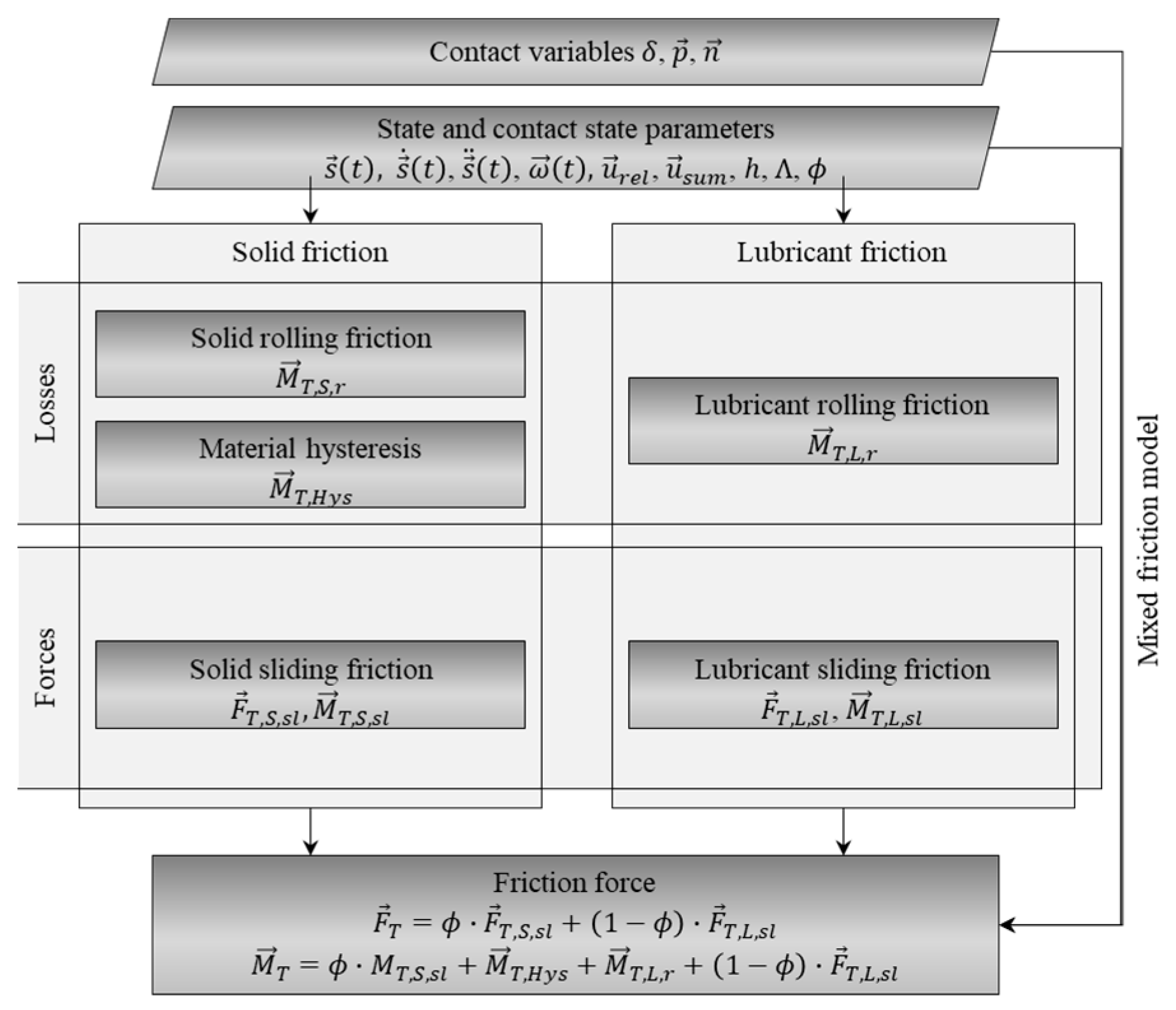
Within the model, a combination of commercial software and self-programmed calculation routines is used. Depending on the level of detail, all bodies of a rolling bearing are modeled with their real geometries. In this work, the most detailed model structure available is described. In order to define the bodies, markers, forces, and boundary conditions, a graphical user interface is used. It was also developed in this work and can access a database of selected bearings and lubricants. This allows for user-friendly model generation. The force elements of the model use the self-written routines to calculate the individual force components in the contact (normal force, damping, and friction). The flow chart in Figure 1 shows a simplified diagram of the procedure followed within the MBS model to calculate contact forces between the single elements by means of roller and ring raceway contact.
In the MBS model geometry, material data and lubricant properties are defined. Together with the state parameters, this data is retrieved from the calculation core. In this case, state parameters mean, for example, the distance s t between the coordinate systems of the individual bodies and their velocities s ˙ t . Based on these, the contact between the rolling element and raceway is determined (see Section 2.1.1). The result values of the contact routine are contact point p , contact normal vector n and penetration δ . With a load-deformation relationship, the effective contact normal force F N . is determined from the penetration. In the next step, the time-dependent contact state parameters are calculated. These are the relative velocities u r e l and sum velocities u s u m in the contact point. The relative velocity is further used to calculate the damping forces F D as described in Section 2.1.2. The normal forces, velocities, and lubricant data are used to determine the lubricant film height h in contact, the specific lubricant film height Λ and the solid load-bearing ratio ϕ . On their basis frictional forces F T and resulting torques M T are calculated. The calculation of frictional forces for each contact in the model is presented in detail in Section 2.1.3. In the last step, the three components of the contact force F Σ are summed up and given back to the MBS solver for iteration of the force equilibrium.

2.1.1. Contact Calculation

In order to correctly represent the contact between two bodies, the area of contact must be discretized. Depending on the type of contact, the discretization used in this model can be one- or two-dimensional. In the case of a roller ring raceway contact, where there is line contact, disc models are the state of the art and are also used here. Depending on the geometry pairing, the contact between the rolling element face and the ring rib deviates greatly from the idealized point or line contact. Therefore, a cell model is used to calculate this contact.

Slice Model

A conventional slice model is described in [62]. In this work, the Alternative Slicing Technique (AST) is used. It was first presented by Teutsch in [63] and subsequently implemented by Kiekbusch for different types of bearings in [26]. The AST model allows radial deformation of the slices toward each other. However, the discs cannot twist against each other. Thus, the deformation of each slice can be determined by its penetration into the contour of the opposite slice of the raceway. Conventional slice models neglect the influence that neighboring slices have on each other. As a result, they do not adequately represent the pressure distribution under bearing loads, especially with tilting. The disk model (AST) used here allows the calculation of excess pressure in the case of edge bearing or strong angular misalignments.

Cell Model

Contact geometries that cannot be reduced to a point or a line are calculated with cell models. One example is the contact between the rolling element’s end face and the inner ring rib. Depending on the profile at the rolling element end face and the ring rib, the contact area can take a crescent shape. For contact calculation, a limited area of the ring and the rolling element end face is divided into squares. Based on the body geometry, the penetration between the contact partners is calculated. For this purpose, the contact problem as described in Polonsky and Keer is solved [64]. The surface deformation is described by an influence matrix. It can be determined according to the Boussinesq equation [65]. Kiekbusch shows in [60] that the problem can be solved most effectively in dynamics simulation with a combination of FFT (Fast Fourier Transformation) and CG (Conjugate Gradient) solver methods. Accordingly, the method described there is used in this work.

2.1.2. Damping

In dynamics simulation, parametric damping models are often used since a variety of influencing factors make it difficult to determine the exact damping values of the contact points. Material damping occurs as a result of deformations and the non-linear elastic properties of contact partners. An additional damping effect is lubricant film damping, which occurs in the run-in zone of the Elasto-Hydrodynamic Lubrication (EHL) contact between the rolling element and raceway [66]. In this study, a parametric model is also used to model the damping force between the rolling element and the other bearing components—the ring raceway, ring ribs, and cage pocket. It is determined by two parameters, the maximum damping coefficient d m a x and the penetration δ m a x , above which maximum damping is reached. Thus, it represents an easily adjustable modeling variant of the damping.
F D v N , δ m a x , d m a x = v N · d
The direction of the damping force is opposite to the impact velocity, which can be understood as the relative velocity of the two touching bodies in the normal direction v N . The damping value d is calculated as a function of the penetration depth δ .
d = 0   f o r   δ < 0 f d δ m a x , d m a x , δ   f o r   0 δ < δ m a x d m a x   f o r   δ δ m a x
It is described in the range 0 δ < δ m a x with a continuous cubic function.
d = 2 · d m a x δ m a x 3 · δ 3 + 3 · d m a x δ m a x 2 · δ 2
The damping model is applied to each disc or cell of the contact, depending on the contact point in the bearing.

2.1.3. Friction

The mathematical and physical principles for describing friction at the contact points in rolling bearings are complex since different friction phenomena occur depending on the contact geometry and relative motion. Rolling and sliding friction are essential for the contact between the rolling element and raceway. Pure rolling occurs when the surface velocities of the contact partners are equal in terms of magnitude and direction. If there is a tangential relative movement between the two contact partners in the contact area, sliding occurs. Both forms of friction are present in the developed model. Losses resulting from non-linear elastic material behavior are here shown as hysteresis moments. Figure 2 gives an overview of the friction components considered. These are calculated for each slice in the discretized contact.
In the following, the implemented approaches to describing the friction components are explained.

Lubricant Friction (Sliding)

In EHL contact, a distinction can be made between a rolling and a sliding component of the frictional force [67]. The sliding component results from the shear of the lubricant. The relative movement (sliding) between the rolling element and the ring raceway shears the lubricant. The resulting shear stresses τ E H L work against the movement of the rolling element. The force acting on the roler can be written as the integral of the shear stresses over A, which is the contact area between the rolling element and ring raceway.
F T , L , s l = ± τ E H L d A
If a constant equivalent shear stress τ E H L is taken as a basis, the relationship can be formulated as follows [67].
F T . L , s l = ± τ E H L · A H e r t z
For the contact area A, the Hertzian contact area A H e r t z is used as a basis. This approach can also be formulated in discrete time if τ E H L and A H e r t z are known at each time step. The two models described below are available in LaMBDA for estimating the equivalent shear stress.
Bair and Winer assume that the shear stresses that a lubricant can carry are limited to a certain value, a limiting shear stress τ L . This value is a characteristic of the lubricant. The viscous component of the shear gradient γ ˙ can be calculated from the quotient of the lubricants limiting shear stress τ L . and η as a logarithmic function [68].
γ ˙ = τ L η · ln 1 τ E H L τ L
The dynamic viscosity η is described by the modulus equation according to Dicke [69].
η = η 0 · e p a 1 + a 2 · ϑ + b 1 + b 2 · ϑ · p
The parameters a 1 , a 2 , b 1 and b 2 of the equation must be determined for each oil from viscosity measurements. The lubricant viscosity η 0 at ambient pressure is calculated according to Vogel with the lubricant-dependent parameters K, B, and C [69]. The parameters describe the temperature dependence of the viscosity. The contact pressure is assumed to be p.
η 0 = K · e B ϑ + C
The temperature ϑ is given in °C in this equation. For the calculation of the heat of compression in the contact area, Gold et al. [70] propose the following relation:
T = T 0 1 2 · C 2 C 1 + C 2 2 · C 1 2 + p C 1
The constants C 1 and C 2 are lubricant dependent. The relative velocity in contact u r e l and the lubricant film height h 0 are used to calculate the shear rate γ ˙ [71].
γ ˙ = u r e l h 0
The relative velocity is calculated from the surface velocities of the two bodies, the roller and the ring. The equations presented by Moes are used to calculate the lubricant film height. The numerical implementation of these equations is presented in [14] and is also used here. In addition, lubricant viscosity is considerably influenced by thermal effects [44]. To take these into account, correction factors ϕ ϑ are used.
h t h = ϕ ϑ · h 0
The relationship according to Zhu and Cheng takes into account not only the relative motion in the contact but also the influence of the maximum Hertzian pressure [72].
ϕ ϑ = 1 13.2 · p 0 E · Γ Z C 0.42 1 + 0.213 · 1 + 2.23 · s Z C 0.83 · Γ Z C 0.64
E is the reduced Young’s modulus of both contacting bodies and p 0 is relative pressure. Deviations from perfect rolling, slippage is included as follows.
s Z C = 2 · u r e l u s u m
For the thermal load parameter Γ Z C , Zhu and Cheng [73] take the temperature gradient of the viscosity as a basis in addition to the average conveying velocity u a v and the thermal conductivity λ ϑ .
Γ Z C = η ϑ · u a v 2 λ ϑ
This can be calculated by differentiating the equation according to Vogel [74].
η ϑ = B V C V + ϑ 2 · A V · e B V C V + ϑ
The parameters A V , B V and C V are pressure- and temperature-dependent quantities that must be determined for each lubricant from viscosity measurements [74].

Lubricant Friction (Rolling)

Rolling resistance results from compressing and overrolling the lubricant in EHL contact. It is calculated according to Biboulet and Houpert [75]
F T , L ,   r = E · R · L · 1.4 · 2 · U 0.5 · W 0.5 0.985 · 1 + 1.4 1.45 · W 2 · U 10 1 10
E and R are the reduced Young’s modulus and the reduced radii of the contacting bodies and L the effective contacting length. The dimensionless parameters of these approaches are defined as follows:
Velocity   parameter U = η 0 · u a v E · R '
Load   parameter W = Q L · E · R
The load parameter W is calculated on the basis of the load Q imposed on one slice of the rolling element.

Solid Rolling Friction

Rolling friction losses due to contact point displacement in the rolling direction caused by elastic deformation of the contact partners are taken into account as a function of normal force, as in Scheuermann [76].
M T , S , r = c r · F N e r
The rolling resistance exponent e r and the rolling friction coefficient c r are material-dependent and can be taken from the literature on the subject or experiment.

Material Hysteresis

Hysteresis refers to a contact that does not take place ideally elastically. The deformation energy is not completely returned. Part of the deformation energy dissipates into heat [61,77]. For the rolling contact between the rolling element and raceway, this means that the contact pressure is asymmetrical. When rolling under load, the contact elements deflect on the run-in side. However, due to the processes described, the deflection does not occur to the same extent. The force Q resulting from the compression is offset relative to the axis of rotation. It therefore causes a moment M T , H y s , which is directed in the opposite direction to the rotary motion of the two bodies. The resulting moment is independent of the velocity. According to Johnson, it can be described as a function of a hysteresis loss factor a v and is only proportional to the contact load and half of the Hertzian contact width b, which corresponds to the disk width in the discretized contact [78].
M T , H y s = Q · a v · 2 b 3 π

Solid Sliding Friction

In order to represent the proportion of solid friction in the contact between rolling elements and the raceway, a section-wise defined function is used. It is divided into a cubic part and a constant part. The distinction is made on the basis of the relative velocities in the contact. Using the input parameters v s and v d the friction coefficient-relative velocity curve can be adapted to experimentally determined values. Above the limit of v d , a constant value μ d is assumed for the solid friction.
μ = h c u b i c + δ c u b i c 2 · 3 2 δ c u b i c   f o r   v s l < v s   o r   v s v s l < v d μ d   f o r   v s l v d
The parameters a c u b i c , h c u b i c , and δ c u b i c are chosen for the ranges such that the value μ i decreases to the constant value μ d after a degressive slope to v s .
a c u b i c = 2 · μ s
f o r   v s l < v s       h c u b i c = μ s
δ c u b i c = v s l + v s 2 v s
a c u b i c = μ d μ s
f o r   v s v s l < v d       h c u b i c = μ s
δ c u b i c = v s l v s v d v s
The resulting frictional force is calculated by multiplying the contact normal force with the described friction coefficient.
F T , S , s l = F N · μ

Mixed Friction

Mixed friction is the transitional area between solid friction and friction due to EHL. Both types of friction are significantly influenced by the surface roughness of the contact bodies. Between the roughness peaks, small micro-EHL structures form, which can only be captured iteratively with great effort. In order to take these effects into account in the dynamics simulation, a simple model according to Zhou and Hoepprich is used [61,73]. It is used to approximate the proportion of solid friction in the mixed friction regime ϕ . This portion can be determined as a first approximation from the asperity load ratio of the surfaces.
ϕ = Q s Q = e B Z H Λ C Z H
The proportion of the normal force Q s transmitted at solid contacts is set in relation to the total load Q here. The parameters B Z H and C Z H describing the roughness of the surfaces and are determined according to [73]. The lubricant film thickness parameter Λ is described as the quotient of the film thickness h 0 and the combined standard derivation of surface roughness σ .
Λ = h 0 σ

Friction in Roller Rib Contact

Friction occurring between the rolling element end face and ring rib is called drilling friction due to the rotational movement the roller is performing. This drilling movement can also be understood as sliding when looking at the relative velocity vector of each discretized point in the contact. The closer the discretized point is to the axis of rotation of the roller, the smaller the magnitude of the velocity. The further away it is, the greater its magnitude becomes. In order to describe the friction that occurs during a sliding movement, suitable approaches exist. Here, a distinction is made between sliding friction in solid contact (rolling element and rib) and the resistance of the lubricant due to its shear.

Solid Sliding Friction in Roller Rib Contact

The coefficient of friction for sliding in solid contact between the rolling element end face and the ring ribs is approximated via a cubic function, as it is used in the roller raceway contact (Equation (21)). In order to define the continuous function necessary for the MBS simulation, the pole point at v s l = 0 is approximated with a cubic section. The parameters v s , v d   μ s and μ d can be used to set the range until a constant friction value is reached.

Lubricant Friction in Roller Rib Contact

The friction component due to sliding in the lubricated contact results from the shear of the lubricant. As in the contact between the rolling element and the ring raceway, Equation (4) is therefore used. The shear stresses in the lubricant are represented by the Bair-Winer model. In this case, in contrast to the line contact, the following equation according to [79] is used to calculate the lubricant film height.
h 0 , i , j = 2.69 · R x · U i , j 0.67 · G i , j 0.53 · W i , j 0.069 · 1 0.61 · e 0.73 · k e
The equation was originally derived for an elliptical contact surface and takes into account the velocity, material, and load using the parameters U i , j , (Equation (33)) G i , j (Equation (34)) and W i , j (Equation (35)). It can be used in good approximation also for this kind of contact, even if the contact area deviates strongly from an ellipse in some cases. The elliptic parameter k e is the ratio of the two contact axes a and b. It can be estimated from the reduced radii in x direction R x and y direction R y .
k = a b 1.0339 · R y R x 0.636
The dimensionless parameters for film height calculation result from the following variables:
Velocity   parameter   U i , j = η 0 · u a v , i , j E · R x
Material   parameter   G i , j = α p , i , j · E
Load   parameter   W i , j = Q i , j E · R x 2
For calculation of the material parameter G, the pressure-viscosity coefficient α p is used. The correction of the lubricant film height for a thermal influence and the description of the dynamic viscosity are carried out according to Equations (6)–(15).

Mixed Friction

The resulting friction force is calculated by summing the two friction force components (solid sliding friction and EHL sliding friction, or lubricant shear). Following Steinert, they are weighted with a dimensionless key figure for the solid body friction component [80].
F T = ϕ · F T , S + 1 ϕ · F T , L
The asperity load ratio ϕ is determined according to the approach of Zhou and Hoepprich [61,73] (Equation (30)).

Friction in Roller Cage Contact

The contact between the rolling element and cage pocket contributes only slightly to the total frictional torque of the bearing. There are high relative speeds or predominantly sliding between the two surfaces. Coulomb’s friction law is therefore used to calculate the frictional force.
F T = F N · μ
The friction value μ used as a basis is approximated as in Equation (21). The polarity of the coefficient of friction at zero velocity is thus avoided. The cage is guided by the rolling elements. Therefore, no further frictional contacts are created. The cage cannot touch the bearing rings.

2.2. Friction Torque Measurement

The measurements of the frictional torque were carried out on the friction torque test rig of the MEGT (see Figure 3). The test rig was developed at the MEGT in the framework of Aul’s work [58]. It has been used in many research projects over the past years and has proven itself reliable [26,58,59,60,81]. The test rig allows the frictional torque of a single test bearing to be measured. The outer ring of the test bearing is mounted on a hydrostatic bearing. A beam load cell is used to hold the rotational degree of freedom of the hydrostatic bearing in position while measuring the force required. With the distance between the axis of rotation of the test bearing and the beam load cell, the total frictional torque can be calculated from the measured force.
Furthermore, the test bearing is accessible for additional measurements such as cage or rolling element speed. The bearing can be loaded in the radial and axial directions. The tilting module also allows tilting and/or skewing of the test bearing, which was not used in the investigations presented here.
Three sets of measurements were performed. First, the TRB was loaded axially with 6 kN. The bearing was lubricated with an oil bath. The oil level was initially set to half the roller height. The lubricant used was an ISO VG 100 mineral oil without additives (reference oil FVA No. 3—for lubricant data, see Table A1 in Appendix A). The speed was kept constant until the temperature on the outer ring of the bearing reached the desired level. The speed ramp was then run through within a few minutes so that there was no change in temperature during the measurement. The measurement was taken at two temperatures, according to the setup shown in Table 1.
Second, a constant combined load was then set. The test sequence is the same as for purely axial loading. Then, the speed was varied at two constant temperatures, according to the setup shown in Table 2. The second series of measurements was carried out under combined radial and axial loads. The radial load was applied in a downward direction, meaning the load zone is located in the lower part of the rolling bearing that is well supplied with lubricant. The other boundary conditions were adopted.
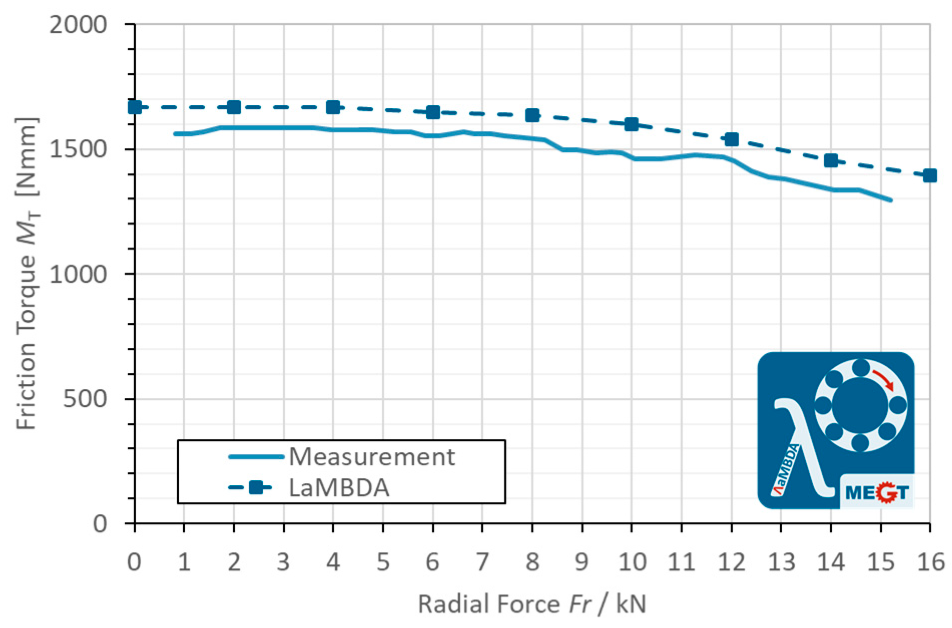
For the last series of measurements, a constant preload of 6.5 kN of the bearing was applied. At constant speed, the radial load was increased from 1 to 15 kN. These measurements have been performed under a steady temperature. The setup parameters are listed in Table 3.
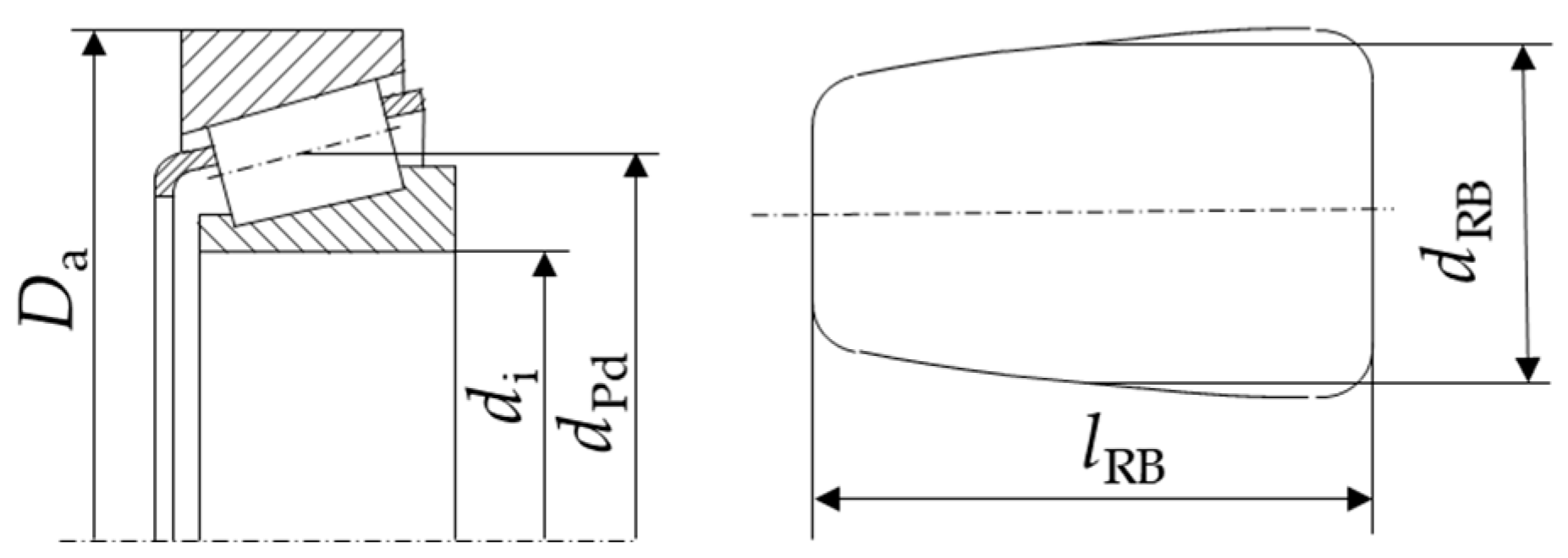
A TRB of type 32216 was used for all tests. The geometry of the bearing is shown in Table 4.
Figure 4 serves as an illustration of the geometric values. The profile retraction of the rolling elements is described by the parameters ap, cp, dp, kp and re. They are defined in Teutsch [44] and allow the different standardized profiles of rollers to be described mathematically.

3. Results

For model validation, the comparison of the frictional torque as an integral parameter of the contact modeling of all internal contacts in the bearing with the measured frictional torque has proved useful. The fictional torque is highly dependent on the load distribution inside the bearing and its dynamics. For this purpose, the total frictional torque is being used as the main outcome for this comparison.
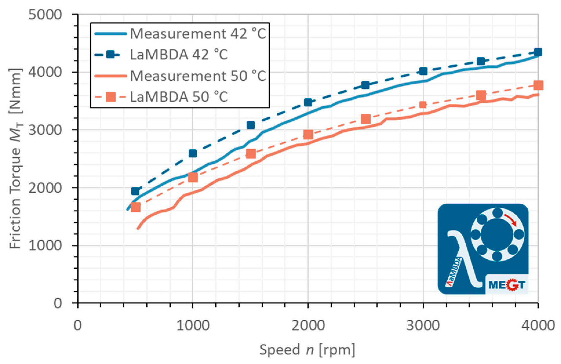
As shown in Figure 5, the frictional torque obtained in the simulation (LaMBDA 50 °C) when submitted to an axial load of 6.5 kN and a shaft speed of 500 rpm is about 1.200 Nmm. The value is rising with an increasing shaft speed up to 3800 Nmm. It can be observed that the simulated friction curve follows the measured one (measurement at 50 °C) with a small offset. The simulated frictional torque values are slightly higher. The second measurement shown in Figure 5 was taken at 42 °C. Since the load is the same, the changed frictional torque can be attributed exclusively to the temperature dependence of the lubricant properties. This concerns especially temperature-dependent changes in viscosity. In the simulation, the lubricant properties are included in the calculation of the rolling resistance as well as the losses due to shear of the lubricant. The fact that the simulated frictional torque follows the measured curve for both temperatures very well shows that the modeling of the lubricant properties is quite suitable.
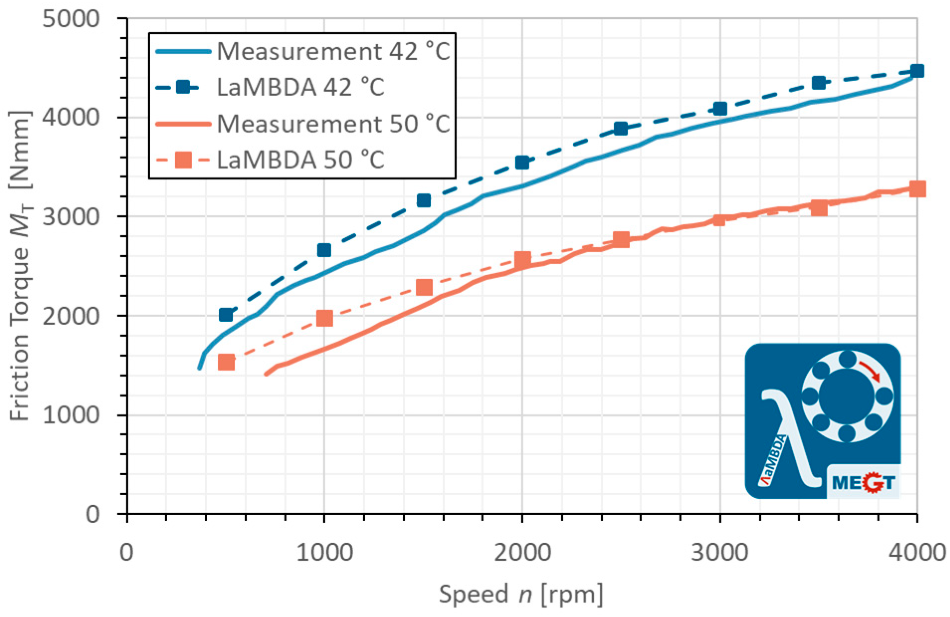
The same experiments were performed with combined axially and radially loaded bearings. This load situation produces significant contact forces in the roller-raceway contact and between roller and rib. Therefore, it is suitable to validate the contact and friction models in the roller-rib contact as well. Both curves, simulation and experiment, show an increase in frictional torque with higher shaft speed and a decrease with lower temperature (Figure 6).
Contrary to expectation, the measured frictional torque is noticeably lower than it is under pure axial load. This results from the changed load distribution in the bearing. Whereas with purely axial loads, the load zone extends over the entire bearing circumference, with additional radial loads, it is located only in the lower part of the bearing. Consequently, fewer rolling elements and thus a smaller contact length contribute to the friction. To investigate this influence further, the radial bearing load is varied at a constant preload. The results from experiment and simulation are presented in Figure 7.
As previously assumed, the measurements carried out (in light blue) show that the total frictional torque of the test bearing decreases with increasing radial load. Again, the comparison between experiment and model shows a very good agreement. The simulation model reproduces all the internal contacts of the bearing individually and in detail, which means that the lower frictional torque is displayed with a radial load component. With the high-resolution contacts and the detailed friction calculation described in Section 2.1, the model is very good at predicting the frictional torque. Furthermore, the model provides an explanation for the falling friction torque curve as it allows an insight into the inside of the bearing and shows the load distribution.
As a second proof of the assumption, the load distribution in the rolling bearing is used. The load distribution for the load cases—pure axial load and combined load with a high radial portion—is shown in Figure 8.
It shows that under pure axial load (left), all rolling elements in the bearing are in the load zone. Thus, all contacts also contribute to the friction. In the load case with an additional radial load of 16 kN, the load zone shifts. It is now located in the lower area of the rolling bearing, which means that only 11 rolling elements are still carrying. This can be seen from the fact that only 12 points are still visible in the diagram. 11 represents the load-carrying rolling elements; all other points are at 0 N since the remaining rolling elements do not experience any load. Accordingly, fewer contacts (effective length) contribute to the friction.

4. Discussion

The preliminary work shows that the dynamics simulations with LaMBDA are well suited to simulate the frictional torque of TRBs at low oil levels or minimum quantities of lubrication. Hydraulic losses due to a higher oil level are not calculated by default with LaMBDA. However, equations exist to take the losses into account. The method, according to Liebrecht, among others, can be regarded as the state of the art [82].
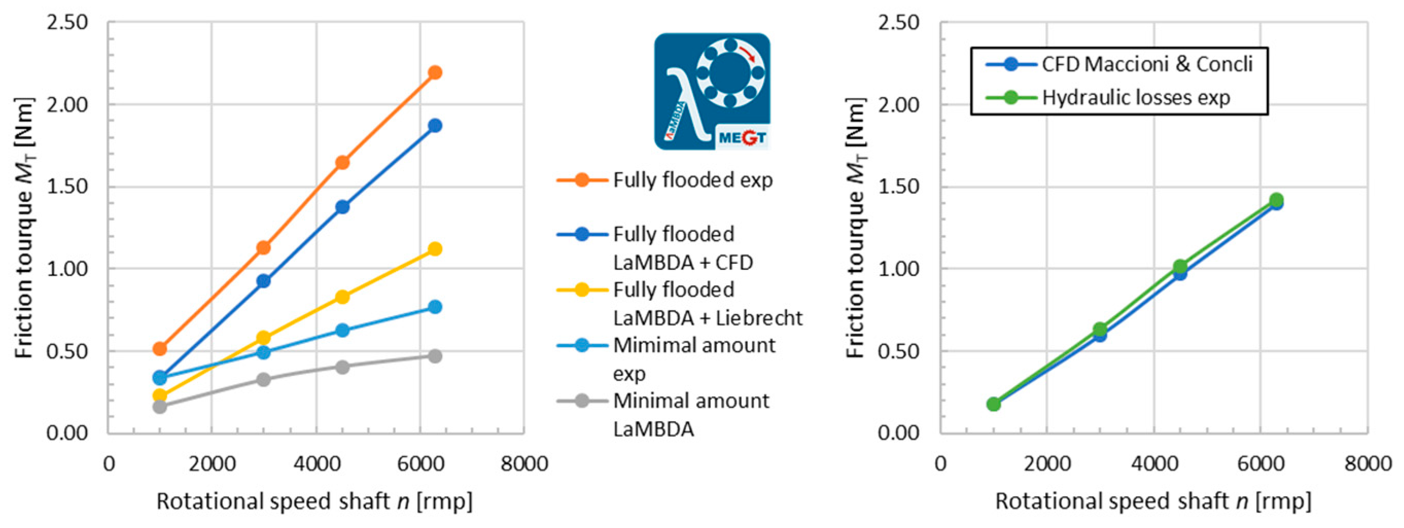
First comparative calculations between LaMBDA simulations and measurements that can be found in the literature, i.e., performed by Liebrecht [82] and Gonda [83], are shown in Figure 9. The measurements had been taken at a test rig where the test bearing and the supporting bearings have separate oil reservoirs to allow the measurement of torques due to the latter bearings independently from the losses of the support bearing [82,83]. While the friction torque simulated with LaMBDA (gray) with minimum quantity lubrication agrees well with the experimentally determined friction torques (light blue), the simulation with a fully flooded test volume (yellow) deviates strongly from the measured friction torque (orange). This means that the state-of-the-art approach (LaMBDA with Liebrecht) greatly underestimates the hydraulic losses in the bearing.
The equations formulated by Liebrecht are derived from experiments with a tapered roller bearing of type 32208 with vertical shaft alignment. They take into account, in addition to the operating conditions, the flow characteristics and simplify the internal bearing geometry. For the operating points investigated, they are simplified as follows:
M d r a g = 0.86 · ρ · l R B · d R B 0.164 · v 0.836 · d m 2.164 · n C 1.164
M c h u r n i n g , O R = 0.32 · ρ · A O R L · d O R L 0.287 · v 0.713 · d m · n C 1.287
M c h u r n i n g , I R = 0.52 · ρ · A I R L · d I R L 0.265 · v 0.735 · d I R L · n I R d m · n C 1.265
While length l R B and diameter d R B of the rolling elements and as well as raceway diameter d O R L resp. d I R L , effective surface A O R L resp. A I R L and d m the mean rolling bearing diameter are geometrical values, the oil density ρ , the dynamic viscosity η and the kinematic viscosity v are lubricant properties. The velocities of the single components are taken into account via the cage speed n C . The oil level is taken into account indirectly via the effective surfaces.
Better results for hydraulic losses can be obtained from the studies in [84] using a Computational Fluid Dynamics (CFD) model developed in an OpenFOAM® environment. The highly specialized CFD simulation obtained agrees with the experiment with only insignificant deviations (see Figure 9 on the right side). In addition, the aforementioned simulations with OpenFOAM® have been validated with respect to lubricant flows in a 32312-A TRB [85,86,87]. Combining the calculated losses from both LaMBDA and CFD simulations, the total bearing losses can be predicted very well (dark blue curve, Figure 9, left). These results show good agreement with the measured total bearing losses (orange). The comparison of the listed calculation methods shows that the state-of-the-art approach predicts the hydraulic losses in a bearing only to a certain extent. With highly specialized CFD simulations, it is possible to determine these losses very precisely [88].
However, there is a need for further research to combine the two methods in order to determine the influence of hydraulic losses on the bearing kinematics. For this purpose, generally applicable equations would have to be derived from the CFD simulation, with which the flow-dependent forces of the lubricant on the bodies in the rolling bearing can be calculated. The forces can then be taken into account in the dynamics simulation and included in the force equilibrium so that they influence the movement—kinematics—of the roller bodies and cage.

5. Conclusions

The developed dynamic model LaMBDA for tapered roller bearings provides very good results with respect to the simulated frictional torque. This has been shown by comparison with friction torque measurements on a single-bearing test rig. Lubricant properties depending on temperature, load, and stresses are correctly represented in the model. The highly accurate contact models and friction descriptions are the basis for the high expressiveness of the model.
Nevertheless, not all losses that occur in a rolling bearing are taken into account. If rolling bearings in a gearbox are to be simulated, the losses due to the oil outside the immediate contact must also be included. Further research is needed in this regard. As shown in the discussion, CFD simulations can make an important contribution to the description of these losses. CFD simulations can also provide information on the lubricant pumping mechanism of the TRB and the lubrication supply, which are not considered in the model yet. A mathematical-physical description of the losses can be derived from the complex flow simulations. In multi-body simulation, these approaches can contribute to the holistic system optimization of gearboxes. Studies on the implementation of these losses in the MBS require further investigation.

Author Contributions

Conceptualization, P.W. and O.K.; methodology, P.W.; software, P.W. and L.M.; validation, P.W.; resources, B.S. and F.C.; data curation, P.W.; writing—original draft preparation, P.W.; writing—review and editing, O.K., F.C.; visualization, P.W.; supervision, B.S. and F.C.; project administration, B.S. All authors have read and agreed to the published version of the manuscript.

Funding

This research was funded by Arbeitsgemeinschaft industrieller Forschungsvereinigungen (AiF) e.V. and Forschungsvereinigung Antriebstechnik (FVA) e.V., FVA project number 625 III, grant number 20764 N.

Data Availability Statement

Data are available on request from the authors.

Acknowledgments

The authors would like to thank the German Research Foundation (DFG) for its support in the context of the experimental work within the framework of the project 430 ”Einfluss der hydraulischen Verluste auf die Reibung von Wälzlagern”, grant numbers SCHW 826/12-1 and SA 898/23-1. The experiments of the two research projects were re-evaluated for this work and included in the discussion of the results obtained here.

Conflicts of Interest

The authors declare no conflict of interest.

Nomenclature

Bearing data
a p Profile parameter
c p Profile parameter
d i Inner diameter
d p Profile parameter
d m mean rolling bearing diameter
d IRL Inner ring raceway diameter
d ORL Outer ring raceway diameter
d Pd Pitch diameter
d RB Roller diameter
k p Profile parameter
l RB Roller length
n RB Number of roller
r e Edge radius
A IRL effective surface of the inner ring
A ORL effective surface of the outer ring
B ZH Surface roughness parameter according to Zhou and Hoepprich
C 0 r Basic static load rating, radial
C ZH Surface roughness parameter according to Zhou and Hoepprich
D a Outer diameter
σ combined standard derivation of surface roughness
Lubricant parameters
a 1 Lubricant dependent parameter according to Dicke
a 2 Lubricant dependent parameter according to Dicke
b 1 Lubricant dependent parameter according to Dicke
b 2 Lubricant dependent parameter according to Dicke
h th thermal corrected lubricant film height
h 0 lubricant film height
A V Lubricant dependent parameter according to Dicke
B Lubricant dependent parameter according to Vogel
B V Lubricant dependent parameter according to Dicke
C Lubricant dependent parameter according to Vogel
C V Lubricant dependent parameter according to Dicke
C 1 Lubricant dependent parameter according to Gold et al.
C 2 Lubricant dependent parameter according to Gold et al.
K Lubricant dependent parameter according to Vogel
α Temperature density coefficient
α p Pressure-viscosity coefficient
η Dynamic viscosity of a lubricant
η 0 Lubricant viscosity at ambient pressure
λ ϑ thermal conductivity
v kinematic viscosity
ρ Lubricant density
τ L Limiting shear stress according to Bair and Winer
ϕ ϑ thermal correction factors
State variables/states
F a Axial load
F r Radial load
n C cage speed
n IR Inner ring speed
N Shaft speed
s Displacement between two coordinate systems
s ˙ Relative velocity between two coordinate systems
s ¨ Acceleration between two coordinate systems
T Absolute temperature
T 0 Ambient temperature (20 °C)
ϑ Temperature in °C
ω Angle between two coordinate systems
ω ˙ Angular velocity between two coordinate systems
ω ¨ Angular acceleration between two coordinate systems
Model input parameters
a cubic Parameter defining the coefficient of friction
a v hysteresis loss factor
c r rolling friction coefficient
e r rolling resistance exponent
L effective contacting length
v s Limit of relative velocity for static coefficient of friction
v d Limit of relative velocity for dynamic coefficient of friction
μ s Static coefficient of friction
μ d Dynamic coefficient of friction
Contact state variables
a Axis of the contact ellipse
b Hertzian contact width/ axis of the contact ellipse
d damping coefficient
d max maximum damping coefficient
f d Function describing the coefficient of damping depending on penetration depth
h lubricant film height
h cubic Parameter defining the coefficient of friction
n Contact normal vector
p Contact pressure
p Contact point vector
p 0 Relative pressure
s ZC Slippage
u av Average conveying velocity of the lubricant
u rel Relative velocity vector in contact point
u rel Magnitude of relative velocity in contact point
u sum Sum velocity vector in contact point
u sum Magnitude of sum velocity in contact point
v N Velocity vector in contact normal direction
v sl Effective sliding velocity
A Hertz Hertzian contact area
E Reduced Young’s modulus of both contacting bodies
F N Magnitude of contact normal force
F N Contact normal force
F D Damping force
F T , L , sl Force resulting from sliding friction in lubricant
F T , S , sl Force resulting from sliding friction in solid contact
F T Traction force
F Σ Contact force
G Material parameter
M churning , IR Churning losses inner ring
M churning , OR Churning losses outer ring
M drag Drag losses
M D Torque from damping force
M N Torque from contact normal force
M T Torque from traction force
M T , Hys Torque resulting from material hysteresis
M T , L , r Torque resulting from rolling friction in lubricant
M T , L , sl Torque resulting from sliding friction in lubricant
M T , S , r Torque resulting from rolling friction in solid contact
M T , S , sl Torque resulting from sliding friction in solid contact
M Σ Torque from contact force
Q load imposed on one slice/cell of the rolling element
Q S proportion of the normal force transmitted at solid contacts
R Reduced radii of the contacting bodies
R x Reduced radius in x direction
R y Reduced radius in y direction
U Velocity parameter
W Load parameter
γ ˙ Shear gradient
δ Penetration depth
δ cubic Parameter defining the coefficient of friction
δ max Penetration above which maximum damping coefficient is reached
μ Coefficient of friction
τ EHL Shear stresses of the lubricant
ϕ Solid load-bearing ratio
Γ ZC Thermal load parameter
Δ t Duration of a time step
Λ Lubricant film thickness parameter

Appendix A

The lubricant viscosity as a function of pressure and temperature was determined with the aid of the modulus equation according to Dicke et al. [69] (Equation (7)) and Vogel [74] (Equation (15)). The parameters used are listed in Table A1.
Table A1. Parameters for viscosity according to Dicke et al. [69] and Vogel [74] for reference oil FVA No. 3.
ParameterVariableValueUnit
Temperature parameter 1K0.062mPa s
Temperature parameter 1B1021.7°C
Temperature parameter 1C101.5517°C
Pressure parameter 1a1327.7918bar
Pressure parameter 1a22.9862bar/°C
Pressure parameter 1b14.419·10−3-
Pressure parameter 1b23.0115·10−41/°C
Density at 15 °Cρ887.6kg/m³
Thermal conductivityλ0.134W/(m K)
Temperature density coefficientα−6·10−4g/(ml K)
1 The lubricant data use in the MBS model in this work have been measured by [89].

Appendix B

For the simulation of the bearing losses at the tapered roller bearing of type 32208 the following geometry was used.
Table A2. Geometrical data of a TRB type 32208.
ParameterVariableValueUnit
Basic static load rating, radialC0r94,000N
Inner diameterdi40mm
Outer diameterDa80mm
Pitch diameterdPd60mm
Roller diameterdRB10mm
Roller lengthlRB17mm
Number of rollersnRB17-
Profile parameterap0.0005-
Profile parametercp16.2mm
Profile parameterdp0.0mm
Profile parameterkp1.0mm
Edge radiusre0.7mm
Combined standard derivation of roughnessσRaceway0.1μm
σRib0.1μm
Mixed friction parameters for raceway contact
according to Zhou and Hoeprich [61,73]
BZH2.1
CZH0.85
Mixed friction parameters for rib contact
according to Zhou and Hoeprich [61,73]
BZH2.1
CZH0.85

References

  1. Woydt, M. The importance of tribology for reducing CO2 emissions and for sustainability. Wear 2021, 474–475, 203768. [Google Scholar] [CrossRef]
  2. Arora, A.; Jha, S.; Saini, V. Aspects of green-sustainable tribology and its impacts on future product development: A review. Ecol. Environ. Conserv. 2019, 25, S146–S157. [Google Scholar]
  3. Takahashi, K.; Suzuki, D.; Nagatomo, T. Effect of Axial Clearance on Rolling Element Load of Double Row Tapered Roller Bearings. Q. Rep. RTRI 2019, 60, 196–201. [Google Scholar] [CrossRef]
  4. Xu, T.; Yang, L.; Wu, Y. Friction torque study on double-row tapered roller bearing. In Proceedings of the 2019 IEEE International Instrumentation and Measurement Technology Conference (I2MTC), Auckland, New Zealand, 20–23 May 2019; pp. 1–6. [Google Scholar] [CrossRef]
  5. Jiang, Z.; Huang, X.; Zhu, H.; Jiang, R.; Du, S. A new method for contact characteristic analysis of the tapered roller bearing in wind turbine main shaft. Eng. Fail. Anal. 2022, 141, 106729. [Google Scholar] [CrossRef]
  6. Venner, C.H. Multilevel Solution of the EHL Line and Point Contact Problems. Ph.D. Thesis, Faculty of Mechanical Engineering, Universiteit Twente, Enschede, The Netherland, 1991. [Google Scholar]
  7. Pan, P.; Hamrock, B.J. Simple Formulas for Performance Parameters Used in Elastohydrodynamically Lubricated Line Contacts. J. Tribol. 1989, 111, 246–251. [Google Scholar] [CrossRef]
  8. Kragelskii, I.V.; Dobychin, M.N.; Kombalov, V.S. Friction and Wear: Calculation Methods; Pergamon Press: Oxford, UK, 1982; pp. 156–207. [Google Scholar]
  9. Muraki, M.; Kimura, Y. Traction Characteristics of Lubricating Oils. 2. A Simplified Thermal Theory of Traction with a Non-Linear Viscoelastic Model. J. Jpn. Soc. Lubr. Eng. 1983, 28, 753–760. (In Japanese) [Google Scholar]
  10. Forster, N.H.; Schrand, J.B.; Gupta, P.K. Viscoelastic Effects in MIL-L-7808-Type Lubricant, Part II: Experimental Data Correlations. Tribol. Trans. 1992, 35, 275–280. [Google Scholar] [CrossRef]
  11. Gupta, P.K.; Cheng, H.S.; Zhu, D.; Forster, N.H.; Schrand, J.B. Viscoelastic Effects in MIL-L-7808-Type Lubricant, Part I: Analytical Formulation. Tribol. Trans. 1992, 35, 269–274. [Google Scholar] [CrossRef]
  12. Houpert, L. Piezoviscous-Rigid Rolling and Sliding Traction Forces, Application: The Rolling Element—Cage Pocket Contact. J. Tribol. 1987, 109, 363–370. [Google Scholar] [CrossRef]
  13. Kannel, J.W.; Bell, J.C. Interpretations of the Thickness of Lubricant Films in Rolling Contact. 1. Examination of Measurements Obtained by X-Rays. J. Lubr. Technol. 1971, 93, 478–484. [Google Scholar] [CrossRef]
  14. Kannel, J.W.; Walowit, J.A. Simplified Analysis for Tractions between Rolling-Sliding Elastohydrodynamic Contacts. J. Lubr. Technol. 1971, 93, 39–44. [Google Scholar] [CrossRef]
  15. Goksem, P.G.; Hargreaves, R.A. The Effect of Viscous Shear Heating on Both Film Thickness and Rolling Traction in an EHL Line Contact—Part I: Fully Flooded Conditions. J. Lubr. Technol. 1978, 100, 346–352. [Google Scholar] [CrossRef]
  16. Dowson, D.; Higginson, G.R. Elasto-Hydrodynamic Lubrication; Pergamon Press: Oxford, UK, 1977; pp. 161–181. [Google Scholar]
  17. Stribeck, R. Ball Bearing of Various Loads. Trans. ASME 1907, 29, 420–463. [Google Scholar]
  18. Sjovall, H. The Load Distribution within Ball and roller Bearings under Given External Radial and Axial Loads. Tek. Tidskr. Mek 1933, 9, 97–102. [Google Scholar]
  19. Lundberg, G.; Palmgren, A. Dynamic Capacity of Roller Bearings. Acta Polytech. Mech. Eng. Ser. R. Swed. Acad. Eng. Sci. 1952, 2, 96–127. [Google Scholar]
  20. Palmgren, A. Ball and Roller Bearing Engineering; SKF Industries Inc.: Philadelphia, PA, USA, 1959. [Google Scholar]
  21. Lundberg, G. Elastische Berührung zweier Halbräume. Forsch. Auf Dem Geb. Des Ingenieurwesens 1939, 10, 201–211. [Google Scholar] [CrossRef]
  22. Palmgren, A.G. Die Lebensdauer von Kugellagern (Life Length of Roller Bearings or Durability of Ball Bearings). Z. Des Vereines Dtsch. Ingenieure 1924, 14, 339–341. [Google Scholar]
  23. Jones, A.B. A General Theory for Elastically Constrained Ball and Radial Roller Bearings under Arbitrary Load and Speed Conditions. J. Basic Eng. 1960, 82, 309–320. [Google Scholar] [CrossRef]
  24. Harris, T.A. Rolling Bearing Analysis; Wiley: New York, NY, USA, 1966. [Google Scholar]
  25. Qian, W. Dynamic Simulation of Cylindrical Roller Bearings—Dynamische Simulation von Zylinderrollenlagern. Ph.D. Thesis, RWTH Aachen, Aachen, Germany, 2014. Available online: https://publications.rwth-aachen.de/record/229010/files/4903.pdf (accessed on 23 August 2023).
  26. Kiekbusch, T. Strategien zur Dynamischen Simulation von Wälzlagern. Ph.D. Thesis, TU Kaiserslautern, Kaiserslautern, Germany, 2017. Maschinenelemente und Getriebetechnik Berichte BD. 23/2017. [Google Scholar]
  27. Hong, S.-H.; Tong, V.-C. Rolling-element bearing modeling: A review. Int. J. Precis. Eng. Manuf. 2016, 17, 1729–1749. [Google Scholar] [CrossRef]
  28. Stacke, L.-E.; Fritzson, D.; Nordling, P. BEAST—A rolling bearing simulation tool. Proc. Inst. Mech. Eng. Part K J. Multi-Body Dyn. 1999, 213, 63–71. [Google Scholar] [CrossRef]
  29. Stacke, L.-E.; Fritzson, D. Dynamic behavior of rolling bearings: Simulations and experiments. Proc. Inst. Mech. Eng. Part J J. Eng. Tribol. 2001, 215, 499–508. [Google Scholar] [CrossRef]
  30. Ioannides, E.; Stacke, L.-E.; Fritzson, D.; Nakhimovski, I. Multibody Rolling Bearing Calculations: Computer Programm BEAST. In Proceedings of the World Tribologie Congress III (WTC 2005), Washington, DC, USA, 12–16 September 2005; pp. 903–904. [Google Scholar] [CrossRef]
  31. Stacke, L.E.; Fritzson, D. Simulation of Rolling Element Bearings. SKF Nova AB S-412 88, SKF, Sweden. 1999. Available online: https://www.researchgate.net/publication/253752292_Simulation_of_Rolling_Element_Bearings (accessed on 28 June 2023).
  32. Aramaki, H. Rolling Bearing Analysis Program Package BRAIN. Motion Control 1997, 3, 15–24. [Google Scholar]
  33. Aramaki, H.; Nakano, Y.; Shoda, Y. Rolling Bearing Analysis Codes BRAIN—The Estimation of Rolling Bearing Performance for an Automotive Application. SAE International Congress and Exposition. 1997. Available online: https://www.jstor.org/stable/44731255 (accessed on 23 June 2023).
  34. Hahn, B.; Smolenski, M.; Neukirchner, J. Investigations of New Cage Designs for the Main Bearings in Multi-Megawatt Wind Power Plants. In Proceedings of the 2nd Conference for Wind Power Drives (CWD), Aachen, Germany, 3–4 March 2015; pp. 321–333. [Google Scholar]
  35. Houpert, L. CAGEDYN: A Contribution to Roller Bearing Dynamic Calculations Part I: Basic Tribology Concepts. Tribol. Trans. 2009, 53, 1–9. [Google Scholar] [CrossRef]
  36. Houpert, L. CAGEDYN: A Contribution to Roller Bearing Dynamic Calculations Part II: Description of the Numerical Tool and Its Outputs. Tribol. Trans. 2009, 53, 10–21. [Google Scholar] [CrossRef]
  37. Houpert, L. CAGEDYN: A Contribution to Roller Bearing Dynamic Calculations. Part III: Experimental Validation. Tribol. Trans. 2010, 53, 848–859. [Google Scholar] [CrossRef]
  38. Development of the Industry’s Highest Precision and Fastest Integrated Bearing Dynamic Analysis System (IBDAS). Available online: https://www.ntnglobal.com/en/news/new_products/news201100013.html (accessed on 23 August 2023).
  39. Liu, X.; Deng, S.; Teng, H. Dynamic stability analysis of cages in high-speed oil-lubricated angular contact ball bearings. Trans. Tianjin Univ. 2011, 17, 20–27. [Google Scholar] [CrossRef]
  40. Jin, K.F.; Yao, T.Q. Multi-Body Contact Dynamics Analysis of Angular Contact Ball Bearing. Appl. Mech. Mater. 2013, 444–445, 45–49. [Google Scholar] [CrossRef]
  41. Wang, Y.; Wang, W.; Zhang, S.; Zhao, Z. Investigation of skidding in angular contact ball bearings under high speed. Tribol. Int. 2015, 92, 404–417. [Google Scholar] [CrossRef]
  42. Lacroix, S.; Nélias, D.; Leblanc, A. Four-Point Contact Ball Bearing Model with Deformable Rings. J. Tribol. 2013, 135, 031402. [Google Scholar] [CrossRef]
  43. Qi, Z.; Wang, G.; Zhang, Z. Contact analysis of deep groove ball bearings in multibody systems. Multibody Syst. Dyn. 2015, 33, 115–141. [Google Scholar] [CrossRef]
  44. Sopanen, J.; Mikkola, A. Dynamic model of a deep-groove ball bearing including localized and distributed defects. Part 1—Theory. Proc. Inst. Mech. Eng. Part K J. Multi-Body Dyn. 2003, 217, 201–211. [Google Scholar] [CrossRef]
  45. Sopanen, J.; Mikkola, A. Dynamic model of a deep-groove ball bearing including localized and distributed defects. Part 2—Implementation and results. Proc. Inst. Mech. Eng. Part K J. Multi-Body Dyn. 2003, 217, 213–223. [Google Scholar] [CrossRef]
  46. Shi, Z.; Liu, J. An improved planar dynamic model for vibration analysis of a cylindrical roller bearing. Mech. Mach. Theory 2020, 153, 103994. [Google Scholar] [CrossRef]
  47. Liu, J.; Ni, H.; Zhou, R.; Li, X.; Xing, Q.; Pan, G. A Simulation Analysis of Ball Bearing Lubrication Characteristics Considering the Cage Clearance. J. Tribol. 2023, 145, 1128–1146. [Google Scholar] [CrossRef]
  48. Russell, T.; Sadeghi, F. The effects of lubricant starvation on ball bearing cage pocket friction. Tribol. Int. 2022, 173, 107630. [Google Scholar] [CrossRef]
  49. Deng, S.; Zhao, G.; Qian, D.; Jiang, S.; Hua, L. Investigation of Oil–Air Flow and Temperature for High-Speed Ball Bearings by Combining Nonlinear Dynamic and Computational Fluid Dynamics Models. J. Tribol. 2022, 144, 071204. [Google Scholar] [CrossRef]
  50. Weinzapfel, N.; Sadeghi, F. A Discrete Element Approach for Modeling Cage Flexibility in Ball Bearing Dynamics Simulations. J. Tribol. 2009, 131, 021102. [Google Scholar] [CrossRef]
  51. Nakhaeinejad, M.; Bryant, M.D. Dynamic Modeling of Rolling Element Bearings with Surface Contact Defects using Bond Graphs. J. Tribol. 2011, 133, 011102. [Google Scholar] [CrossRef]
  52. Ashtekar, A.; Sadeghi, F. A New Approach for Including Cage Flexibility in Dynamic Bearing Models by using Combined Explicit Finite and Discrete Element Methods. J. Tribol. 2012, 134, 041502. [Google Scholar] [CrossRef]
  53. Brouwer, M.D.; Sadeghi, F.; Ashtekar, A.; Archer, J.; Lancaster, C. Combined Explicit Finite and Discrete Element Methods for Rotor Bearing Dynamic Modeling. Tribol. Trans. 2015, 58, 300–315. [Google Scholar] [CrossRef]
  54. Ashtekar, A.; Sadeghi, F. Experimental and Analytical Investigation of High Speed Turbocharger Ball Bearings. ASME J. Eng. Gas Turbines Power 2011, 133, 122501. [Google Scholar] [CrossRef]
  55. Tong, V.-C.; Kwon, S.-W.; Hong, S.-W. Fatigue Life of Cylindrical Roller Bearings. Proc. Inst. Mech. Eng. Part J J. Eng. Tribol. 2016, 231, 623–636. [Google Scholar] [CrossRef]
  56. Ghaisas, N.; Wassgren, C.R.; Sadeghi, F. Cage Instabilities in Cylindrical Roller Bearings. J. Tribol. 2004, 126, 681–689. [Google Scholar] [CrossRef]
  57. Singh, S.; Köpke, U.G.; Howard, C.Q.; Petersen, D. Analyses of Contact Forces and Vibration Response for a Defective Rolling Element Bearing using an Explicit Dynamics Finite Element Model. J. Sound Vib. 2014, 333, 5356–5377. [Google Scholar] [CrossRef]
  58. Aul, E. Analyse von Relativbewegungen in Wälzlagersitzen. Ph.D. Thesis, TU Kaiserslautern, Kaiserslautern, Germany, 2008. Maschinenelemente und Getriebetechnik Berichte BD. 05/2008. [Google Scholar]
  59. Mármol Fernández, M. Development of a New Bearing Geometry to Reduce Friction Losses. Ph.D. Thesis, TU Kaiserslautern, Kaiserslautern, Germany, 2022. Maschinenelemente und Getriebetechnik Berichte BD. 43/2022. [Google Scholar]
  60. Kiekbusch, T.; Sauer, B. Calculation of the dynamic behavior of rolling bearings with detailed contact calculations. In Proceedings of the EUROMECH Colloquium 578, Rolling Contact Mechanics for Multibody System Dynamics, Funchal, Portugal, 10–13 April 2017; ISBN 978-989-99424-3-1. [Google Scholar]
  61. Teutsch, R. Kontaktmodelle und Strategien zur Simulation von Wälzlagern und Wälzführungen. Ph.D. Thesis, TU Kaiserslautern, Kaiserslautern, Germany, 2005. Maschinenelemente und Getriebetechnik Berichte BD. 01/2005. [Google Scholar]
  62. DIN ISO 26281; Wälzlager—Dynamische Tragzahlen und Nominelle Lebensdauer-Berechnung der Modifizierten Nominellen Referenz-Lebensdauer für Wälzlager. European Committee for Standardization: Brussels, Belgium, 2010.
  63. Teutsch, R.; Sauer, B. An Alternative Slicing Technique to Consider Pressure Concentrations in Non-Hertzian Line Contacts. ASME J. Tribol. 2004, 126, 436–442. [Google Scholar] [CrossRef]
  64. Polonsky, I.A.; Keer, L.M. A numerical method for solving rough contact problems based on the multi-level multi-summation and conjugate gradient techniques. Wear 1999, 231, 206–219. [Google Scholar] [CrossRef]
  65. Boussinesq, J. Application des Potentiels à l’étude de l’équilibre et du Mouvement des Solides élastiques: Principalement au Calcul des Déformations et des Pressions que Produisent, dans ces Solides, des Efforts Quelconques Exercés sur une Petite Partie de leur Surface ou de leur Intérieur: Mémoire Suivi de Notes Etendues sur Divers Points de Physique, Mathématique et d’analyse; Gauthier-Villars: Paris, France, 1885. [Google Scholar]
  66. Dietl, P. Damping and Stiffness Characteristics of Rolling Element Bearings: Theory and Experiment. Ph.D. Thesis, Technische Universität Wien, Vienna, Austria, 1997. [Google Scholar] [CrossRef]
  67. Wisniewsky, M. Elastohydrodynamische Schmierung. In Handbuch der Tribologie und Schmierungstechnik, 9th ed.; Expert-Verlag: Renningen, Germany, 2000. [Google Scholar]
  68. Bair, S.; Winer, W.O. A Rheological Model for Elastohydrodynamic Contacts Based on Primary Laboratory Data. ASME J. Lubr. Technol. 1979, 101, 258–265. [Google Scholar] [CrossRef]
  69. Peeken, H.; Dicke, H.; Welsch, G. Viscosity-Pressure-Temperature Characteristics of Different Types of Lubricants and their Possible Influence on Fatigue. In Proceedings of the 3rd World Congress on Gearing and Power Transmission, Paris, France, 12–14.February 1992; pp. 527–536. [Google Scholar]
  70. Gold, P.W.; Schmidt, A.; Loos, J.; Aßmann, C. Viskositäts-Druck-Koeffizienten von mineralischen und synthetischen Schmierölen. Tribol. Schmier. 2001, 48, 40–48. [Google Scholar]
  71. Lubenow, K. Axialtragfähigkeit und Bordreibung von Zylinderrollenlagern. Ph.D. Thesis, Universität Bochum, Bochum, Germany, 2002. [Google Scholar]
  72. Aramaki, H.; Cheng, H.S.; Zhu, D. Film Thickness, Friction, and Scuffing Failure of Rib/Roller End Contacts in Cylindrical Roller Bearings. J. Tribol. 1992, 114, 311–316. [Google Scholar] [CrossRef]
  73. Zhou, R.S.; Hoeprich, M.R. Torque of Tapered Roller Bearings. ASME J. Tribol. 1991, 113, 590–597. [Google Scholar] [CrossRef]
  74. Engel, S. Reibungs-und Ermüdungsverhalten des Rad-Schiene-Systems mit und ohne Schmierung. Ph.D. Thesis, Universität Magdeburg, Magdeburg, Germany, 2002. [Google Scholar]
  75. Biboulet, N.; Houpert, L. Hydrodynamic force and moment in pure rolling lubricated contacts. Part 1—Line contacts. Proc. Inst. Mech. Eng. Part J J. Eng. Tribol. 2010, 224, 765–775. [Google Scholar] [CrossRef]
  76. Scheuermann, M. Dynamiksimulation zur Virtuellen Produktentwicklung von Rollenschienenführungen. Ph.D. Thesis, TU Kaiserslautern, Kaiserslautern, Germany, 2010. Maschinenelemente und Getriebetechnik Berichte BD. 07/2021. [Google Scholar]
  77. Stolarski, T.A.; Tobe, S. Rolling Contacts; Professional Engineering Publishing Limited: London, UK, 2000; pp. 55–73. [Google Scholar]
  78. Johnson, K. Contact Mechanics; Cambridge University Press: Cambridge, UK, 1985. [Google Scholar]
  79. Wang, Q.; Chung, Y.-W. Encyclopedia of Tribology; Springer: New York, NY, USA, 2013. [Google Scholar]
  80. Steinert, T. Das Reibmoment von Kugellagern mit Bordgeführtem Käfig. Ph.D. Thesis, RWTH Aachen, Shaker Verlag, Aachen, Germany, 1996. [Google Scholar]
  81. Sebteini, S.; Hudak, R. Mindestlast von Wälzlagern. Abschlussbericht zum Forschungsvorhaben Nr. 830 I (Heft 1504); FVA Forschungsvereinigung Antriebstechnik e.V.: Frankfurt am Main, Germany, 2022. [Google Scholar]
  82. Liebrecht, J. Technisch-Mathematischer Ansatz zur Berechnung der Hydraulischen Verluste in Wälzlagern. Ph.D. Thesis, RPTU Rheinland-Pfälzische Technische Universität Kaiserslautern Landau, Kaiserslautern, Germany, 2018. Maschinenelemente und Getriebetechnik Berichte Bd. 30/2018. [Google Scholar]
  83. Gonda, A.; Sauer, B.; Großberndt, D.; Schwarze, H. Experimentelle und numerische Untersuchungen der hydraulischen Verluste in voll-und teilgefluteten kegelrollenlagern. VDI Berichte 2019, 2348, 97–106. [Google Scholar] [CrossRef]
  84. Maccioni, L.; Ruth, L.; Koch, O.; Concli, F. Load-independent power losses of full-flooded lubricated tapered roller bearings: Numerical and experimental investigation of the effect of operating temperature and housing walls distances. Tribol. Trans. 2023, in press.
  85. Maccioni, L.; Chernoray, V.G.; Mastrone, M.N.; Bohnert, C.; Concli, F. Study of the impact of aeration on the lubricant behavior in a tapered roller bearing: Innovative numerical modelling and validation via particle image velocimetry. Tribol. Int. 2022, 165, 107301. [Google Scholar] [CrossRef]
  86. Maccioni, L.; Chernoray, V.G.; Bohnert, C.; Concli, F. Particle Image Velocimetry measurements inside a tapered roller bearing with an outer ring made of sapphire: Design and operation of an innovative test rig. Tribol. Int. 2022, 165, 107313. [Google Scholar] [CrossRef]
  87. Maccioni, L.; Chernoray, V.G.; Concli, F. Fluxes in a full-flooded lubricated Tapered Roller Bearing: Particle Image Velocimetry measurements and Computational Fluid Dynamics simulations. Tribol. Int. 2023, 188, 108824. [Google Scholar] [CrossRef]
  88. Maccioni, L.; Concli, F. Computational fluid dynamics applied to lubricated mechanical components: Review of the approaches to simulate gears, bearings, and pumps. Appl. Sci. 2020, 10, 8810. [Google Scholar] [CrossRef]
  89. Brouwer, L.; Bader, N.; Beilicke, R.; Schwarze, H.; Poll, G.; Deters, L. Tribologische Fluidmodelle Nebenaggregate—Tribologische Fluidmodelle für Nebenantriebsaggregate in Hybrid- und Elektrofahrzeugen—Abschlussbericht zum FVV-Forschungsvorhaben 597 (Heft 1092); Forschungsvereinigung Verbrennungskraftmaschinen e. V.: Frankfurt am Main, Germany, 2016. [Google Scholar]
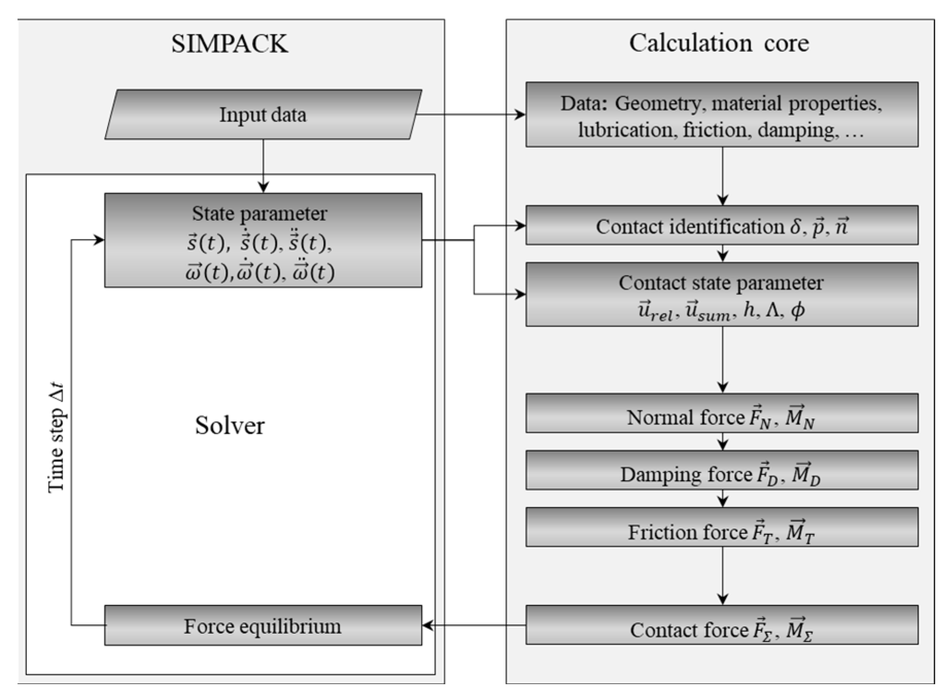
Figure 1. Flow chart of contact force calculation between rolling elements and ring raceways [26].
Lubricants 11 00369 g001
Figure 2. Friction calculation in roller raceway contact of the TRB MBS model [26].
Lubricants 11 00369 g002
Figure 3. Scematic view and CAD model of the friction torque test bench at MEGT [42].
Lubricants 11 00369 g003
Figure 4. Graphical illustration of the geometry parameters of the TRB used in this study. On the left the sectional view of the TRB and on the right a rolling element is shown. The dotted lines represent the symmetry lines of the bearing and the rolling element.
Lubricants 11 00369 g004
Figure 5. Comparison of the measured and LaMBDA-calculated frictional torque of a TRB of type 32216 under purely axial load of 6 kN and oil bath lubrication with reference oil FVA No. 3.
Lubricants 11 00369 g005
Figure 6. Comparison of the measured and LaMBDA-calculated frictional torque of a TRB of type 32216 under combined axial load of 6.5 kN and radial load of 6 kN with oil bath lubrication with reference oil FVA No. 3.
Lubricants 11 00369 g006
Figure 7. Comparison of the measured and LaMBDA-calculated frictional torque of a TRB of type 32216 under combined load and oil bath lubrication with reference oil FVA No. 3 under variation of the radial load at 50 °C.
Lubricants 11 00369 g007
Figure 8. Load distribution of the TRB type 32216 used. Left: with purely axial load of 6 kN, right: with combined load of 6 kN axial and 16 kN radial.
Lubricants 11 00369 g008
Figure 9. Comparison of the simulated frictional torque of a TRB of type 32208 under oil sump lubrication with reference oil FVA No. 3 at 50 °C and an axial load of 1 kN with the measured frictional torque on a single-bearing test rig. Simulated frictional torque with LaMBDA and experiment (left), experiment and CFD simulation [84] (right). Bearing data is provided in Table A2 in Appendix B) and lubricant data in Table A1 in Appendix A).
Lubricants 11 00369 g009
Table 1. Test setup for friction torque measurement of a TRB type 32216 at pure constant axial load.
ParameterVariableValueUnit
Axial loadFa6kN
Radial loadFr0kN
Temperature ϑ 42 and 50°C
Shaft speedN500–4000rpm
Lubrication Oil bath half roller height
Lubricant Reference oil FVA3
Table 2. Test setup for friction torque measurement of a TRB type 32216 at combined, constant axial and radial load.
ParameterVariableValueUnit
Axial loadFa6kN
Radial loadFr6.5kN
Temperature ϑ 42 and 50°C
Shaft speedN500–4000rpm
Lubrication Oil bath half roller height
Lubricant Reference oil FVA3
Table 3. Test setup for friction torque measurement of a TRB type 32216 at combined load.
ParameterVariableValueUnit
Axial loadFa6.5kN
Radial loadFr1–15kN
Temperature ϑ 50°C
Shaft speedN2000rpm
Lubrication Oil bath half roller height
Lubricant Reference oil FVA3
Table 4. Geometrical data of a TRB type 32216.
ParameterVariableValueUnit
Basic static load rating, radialC0r260,000N
Inner diameterdi80mm
Outer diameterDa140mm
Pitch diameterdPd108.5mm
Roller diameterdRB17mm
Roller lengthlRB22.7mm
Number of rollernRB16-
Profile parameterap0.0005-
Profile parametercp20.7mm
Profile parameterdp0.0mm
Profile parameterkp2.0mm
Edge radiusre1.0mm
Combined standard derivation of roughnessσRaceway0.16μm
σRib0.24μm
Mixed friction parameters for raceway contact
according to Zhou and Hoeprich [61,73]
BZH2.32
CZH0.97
Mixed friction parameters for rib contact
according to Zhou and Hoeprich [61,73]
BZH1.90
CZH0.99
Disclaimer/Publisher’s Note: The statements, opinions and data contained in all publications are solely those of the individual author(s) and contributor(s) and not of MDPI and/or the editor(s). MDPI and/or the editor(s) disclaim responsibility for any injury to people or property resulting from any ideas, methods, instructions or products referred to in the content.