1. Introduction
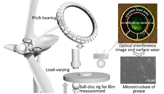
Tribological interfaces in machine elements are frequently subjected to vibration or load-varying conditions, such as those encountered in the pitch bearings of wind turbines during the braking phase in the case of strong wind. Despite the absence of macroscopic motion between the rolling elements and the raceway, the contacting interfaces may suffer from dynamic loads to resist the upsetting moments induced by the blade–wind interactions. It is challenging to form hydrodynamic lubricating films for such load-varying conditions as a result of the low entrainment velocity, and mixed/boundary lubrication is expected to predominate. Surface damage, including false brinelling and surface wear [
1,
2], is prevalent as the interfaces undergo long periods of variable loads. These failures can exacerbate vibration and reduce the reliability and longevity of wind turbines and/or similar mechanical systems [
3].
The lubrication state is considered transient when parameters such as load, type of motion, entrainment velocity, contact geometry, and lubricant supply vary over time [
4], according to the (elasto)-hydrodynamic lubrication (EHL) theory. Notably, motions that typically lead to transient lubrication problems include reciprocating motion, start/stop, acceleration/deceleration, impact, and variable load motion. These transient lubrication problems exhibit unique characteristics and may not align with the classical lubrication theory of steady state. For instance, in reciprocating motion, commonly observed in pitch bearings, both the magnitude and direction of velocity vary with time. The minimum film thickness appears after but not right at the reciprocating ending points attributed to the combined effects of hydrodynamics and squeeze [
5,
6]. This type of oscillatory motion in wind turbines has been extensively studied using ball-on-disc model test rigs and down-sized bearing tests [
7,
8,
9]. The decay of the grease-lubricating film over time has been well documented, with starvation identified as the primary cause of wear damage to the surface. However, most of the experiments have been performed with model grease, either without additives or with commercial grease whose additive packages are unknown. It is widely recognized that active sulphur and phosphorus elements present in additives contribute to the formation of tribo-films under appropriate mechano-chemical conditions, thereby enhancing anti-wear properties. The decomposition of organic molybdenum on the surface of a highly loaded friction sub-surface produces MoS
2, phosphides, and sulphides that are deposited and adsorbed in the contact area, providing friction reduction and anti-wear [
10,
11]. Apart from the starvation lubrication mechanism, the role of anti-wear additives and tribo-chemistry remains largely unexplored. From a practical point of view, it is interesting to know whether appropriate anti-wear additives could mitigate surface damage during reciprocating or other types of transient motion. In addition, the behavior of grease under load-varying lubrication conditions has not yet been investigated. As the applied load varies, the size of the contact zone changes, potentially causing micro-slip at the edges of the contact zone. The grease in the variable load zone experiences variable loads, leading to film thickness decay over time and an increased risk of failure. Therefore, it is necessary to study the lubrication behavior of grease under load-varying conditions by examining the film thickness variation and evaluating the effectiveness of anti-wear additives.
Grease, a non-Newtonian fluid in a semi-solid state, serves as the primary lubricant for bearings in wind turbines, as well as for other applications. It is composed of a thickener, base oil, and various additives. The presence of a thickener allows grease to form a thicker deposit and lubricating film under specific operating conditions, such as at heavy loads and/or low speeds [
12,
13,
14]. Over long-term operation, the lubrication performance of grease is related to replenishment [
15,
16], its rheological property [
17,
18,
19], and degradation [
20,
21]. A single dimensionless parameter, based on replenishment local to the contact, has been established between the operating parameters and the transition from the fully flooded to the starved regime by Cann [
22,
23]. Li et al. analyzed the formation of equilibrium oil films determined by the balance of lubricant loss and replenishment under the long-term rolling condition, as well as under the sliding–rolling condition [
24,
25]. This work identifies the main mechanisms that dominate oil film formation in different lubrication contacts. Many studies have explored the lubrication characteristics of grease under non-steady states, including reciprocating pure sliding [
26], reciprocating pure rolling [
27], cyclic impact [
28,
29,
30], impact-sliding composite motion [
31,
32], and vibratory motion [
33]. It is important to note that the influence of time-varying factors on the lubrication effect of grease is very complex. Whether unsteady motion enhances or hinders grease lubrication depends on the specific form of the motion. For instance, one study indicated that loading/unloading favors grease replenishment [
34], while changes in speed direction during reciprocating motion aggravate starvation [
27].
Motions with load-varying conditions have been studied extensively from the perspective of wear. Radial fretting, one of the four modes of fretting, is mainly induced by varying normal load. The contact pair undergoes a long period of radial variable load motion, either dry contact or lubricated contact, leading to radial fretting occurring on the material surface due to small-scale changes in the contact zone [
35,
36,
37,
38]. Recent investigation by the authors into the distribution of the grease film thickness during the transition from reciprocating motion to micro-oscillation revealed correlations between the lubricating film formation and surface wear [
39]. Notably, the locations of reduced film thickness or rupture were found to align closely with the locations of severe surface wear. However, the lubricating film behavior in the load-varying regions remains unclear for fresh grease.
The influence of the chemical compositions of grease on the lubricating film behavior under load-varying conditions has been less well understood. In particular, studies examining the effectiveness of anti-wear additives on surface wear under such conditions are scant. It should be highlighted that this paper assumes an initial clearance (gap height) of 0 with an initially applied non-zero load, a scenario distinct from studies on impact EHL which involves an initial clearance. This study focused on the grease-lubricating film formation, decay, and surface wear in terms of grease soap content, anti-wear additives, and dynamic load variation ranges. The decay in the film thickness and changes in microstructure of the greases were observed over cycles. This study aims to gain insights into the failure mechanism of grease under radial variable load conditions from the perspective of the EHL and boundary lubrication.
2. Materials and Methods
Lubricating film thickness is an important parameter for evaluating the state of lubrication. In 1965, Cameron et al. [
40,
41] proposed the ball-on-disc experimental method, using optical interference techniques to observe the oil film shape in contact. Through the continuous improvement of the technology of optical interferometry and related hardware, it is possible to detect dynamic film thickness in a timely manner.
The experiment was carried out on a customized ball-on-disc test rig, as depicted schematically in
Figure 1. The load variation function was facilitated by a servomotor that propels the steel ball (one-inch diameter) up and down onto a disc. The disc can be either glass, suitable for optical measurement of the lubricating film, or steel and test the effectiveness of anti-wear additives. The glass disc is 15 mm thick, and the working side in contact with the ball is coated with a thin semi-reflective Cr film to enhance the quality of interference images. The optical interference measurements utilized a red-green laser light source. The method used for film thickness measurements in this study is the dichromatic interference intensity modulation technique (DIIM) developed by Liu et al. [
42]. The physical properties of the steel ball, glass disc, and steel disc are listed in
Table 1. It should be noted that the steel discs are custom polished to a roughness of around 20 nm to 30 nm.
Apparent viscosity data for greases with three soap contents at 25 °C are given in
Figure 2. The Anton Paar MCR302 rheometer (Anton Paar Gmbh, Graz, Austria) was applied. The apparent viscosity was tested in rotation mode with shear rates from 0.1 s
−1 to 100 s
−1. The apparent viscosities of lithium greases with 20–30% soap content are not given in the figure because the grease is in too hard a state, which makes rheological testing difficult.
To investigate the effect of additives on fretting corrosion prevention in grease-lubricated contacts, tribological tests were first carried out with the configuration of the steel ball in contact with the steel disc. After the tribological tests, the steel disc was replaced with a glass disc to facilitate the acquisition of an optical interference image with the ball and to assess the wear and tribo-film formation on the surface of the steel ball. This is illustrated in
Figure 1b.
The grease used in the experiments is laboratory-produced lithium grease. The base oil is PAO8, and the soap content varies from 5% to 30% resulting in different NLGI classes. The specific parameters of the greases are detailed in
Table 2. All anti-wear additives used are commercially available. Specifically, additives 349, 353, and 232 additives are from BASF’s IRGALUBE series (Ludwigshafen, Germany). The additive Mol is sourced from Vanderbilt Chemicals, LLC (Norwalk, America), and Additive 306 is from Tanee Chemical Ltd. (Beijing, China). Notably, Additives 349 and 306 exclusively contain phosphorus, whereas the additives Mol, 232, and 353 contain both sulphur and phosphorus. Each additive was added to the grease at a concentration of 2% by weight, followed by three rounds of grinding of the grease using a grinder to ensure uniform distribution. Experiments were conducted at room temperature: 25 °C.
Figure 3 illustrates the motion patterns for variable loads, which are categorized into three distinct load ranges (green line:5 N–50 N, blue line:25 N–50 N, and red line:40 N–50 N).
Table 3 gives all the parameters for the seven sets of experiments, including and combining tests of three load-varying ranges, six soap contents, and with/without five anti-wear additives. After the tribological and optical tests, the grease present on the rubbing track of the steel disc was re-examined to check the change in the micro-structure of the thickener. This was performed by mechanically cutting the steel disc with the tested grease intact, followed by a 72 h immersion in petroleum ether to dissolve the base oil and isolate the thickener. Subsequently, the micro-structure of the grease around the variable load zone (see
Figure 3b) was characterized using field emission scanning electron microscopy (FE-SEM, JEOL Ltd., Musashino City, Japan).
3. Results
3.1. Effect of Load-Varying Range
Figure 4 shows the optical interferometric images of grease Li-10% (10% indicates thickener contents of the base grease) during loading/unloading at various cycles, namely, the 1st, 20th, 50th, 200th, 500th, 1000th, and 3000th.
Within each cycle, the load first increases from 5 N to 50 N and then decreases to 5 N, with a cycle duration of 0.4 s. Images of representative instants such as 0 T, 1/8 T, 1/4 T, 3/8 T, 1/2 T, 5/8 T, 3/4 T, 7/8 T, and 1 T are shown from left to right in a row. The initial motion reveals a contact zone abundant with thickener fibers/clusters. As the loading proceeds, the contact zone expands progressively, trapping new thickener to enter from the periphery of the contact zone, thereby increasing the total amount of thickener within the contact zone. Note that this is solely caused by the load-varying only, as there is no macroscopic rolling or sliding of the surface. Furthermore, the fiber/clusters present at the initial 0 T instant persist in the contact zone without any noticeable morphological changes. The film thickness distributions at the symmetry instants during one loading/unloading cycle exhibit high similarity, e.g., at the 1/8 T and 7/8 T instants.
With an increase in the number of cycles, the thickener clusters in the contact area become squeezed and slightly thinner by the 20th cycle, yet two distinct aggregated clusters remain at the center of the contact area, as indicated by the red segment in the interferometric image. These clusters have been present since the beginning of the motion, as evidenced by the image of the 1st cycle. As the load-varying motion continues, the fiber clusters in the contact zone decrease gradually, even though throughout the initial 500 cycles these fiber clusters consistently remain at the center of the contact zone. By the 1000th cycle, the fiber clusters are nearly invisible in the contact zone, with only a few arc-shaped clusters present during the 1/4 T–3/4 T intervals. The curved shape of film distribution bears a resemblance to the edge of the contact zone at the 0 T instant, i.e., the 5 N condition. This observation suggests that the fiber clusters which entered the contact zone at the 5 N moment affect the grease film thickness distribution for subsequent cycles.
Figure 5 shows the film thickness profile of the middle section across the contact zone corresponding to
Figure 4, with measurements at the position of the dotted line marked in
Figure 4 during the 1st cycle at 0 T. The figure reveals that during the first cycle, the film thickness in the contact zone exhibits a more pronounced fluctuation, with the maximum film thickness reaching approximately 200 nm. By the 50th cycle, the whole contact area gives a pattern of high film thickness in the center and low film thickness at the edges. The film thickness in the variable load zone is as low as about 50 nm. By the 1000th cycle, the central film thickness (the bump) is no longer evident, with a minimum film thickness of merely 10 nm. Upon reaching the 3000th cycle, the film thickness distribution is similar to the 1000th cycle.
Figure 6 shows the optical interference images during the load-varying cyclic process with a reduced range of load variation from 25 N to 50 N. Since the film morphology of the unloading process closely mirrors that of the loading process, only the image during the loading process is given here. The phenomenon at the 1st cycle is consistent with that in
Figure 4, where an increase in load results in a larger amount of thickener fiber in the contact zone. As the number of cycles increases, the amount of thickener in the contact zone diminishes. By the 50th cycle, a ring-shaped region of low film thickness appears in the variable load zone, caused by the continuous discharge of fiber clusters outside the contact zone throughout the cyclic loading process. The grease in the variable load zone is discharged quickly, contrasting with the slower grease discharge observed in the stick zone. In contrast to the results of the 5 N–50 N range of load variation in
Figure 4, at the 1000th cycle, a distinct presence of thickener fiber remains in the center of the contact zone. Until the 3000th cycle, the thickener fiber clusters gradually vanish.
The corresponding mid-section film thickness curves for the aforementioned working conditions are given in
Figure 7. The film thickness was measured at the position of the dotted white line in
Figure 6. The trend of variation in film thickness is similar to that observed in
Figure 5. During the initial stages of the load-varying motion, the film thickness is notably high, approximately 150 nm. From the 50th cycle to the 1000th cycle, the film thickness profile in the contact zone shows a high film thickness in the middle and a low film thickness around. This is consistent with the information from the optical interferogram, which indicates a reduced amount of fiber clusters in the variable load zone and an increased presence in the stick zone. By the 3000th cycle, the film thickness across the entire contact zone is approximated to be between 10 nm and 20 nm.
Figure 8 shows the optical interference images for a more limited range of load variations, specifically from 40 N to 50 N. The images demonstrate significant differences when compared to the previous results. Throughout the motion which lasted up to 3000 cycles, the thickener fiber in the contact zone remained largely unchanged. Only a minor discharge of thickener fiber was observed near the edge of the contact zone. This can be attributed to the small load variations, resulting in a small variable load zone. The distribution of grease thickener is dynamic; the thickener discharge and entry into the contact zone depends on the grease flow caused by the surface movement. Under this condition, the magnitude of surface movement is small, and therefore the grease flow effect is small.
3.2. Effect of Soap Content
The optical interferograms of grease with a 5% soap content (Li-5% base grease) under varying load conditions are given in
Figure 9 for selected cycles: 1st, 20th, 50th, 200th, 500th, 1000th, and 3000th. In the first cycle, an arcuate distribution of grease thickener fiber clusters appeared between 1/4 T and 1/2 T in the contact zone. By the 20th cycle, there was a notable decrease in these clusters, and by the 1000th cycle, they were almost invisible. These clusters vanished from both the slip and stick zones. It is noteworthy that at the 3000th cycle, few curved-distribution fiber clusters appeared, potentially due to the migration of grease. Compared to the results with the soap content of 10% in
Figure 4, the discharge rate of thickener fiber from Li-5% is faster. For the same number of cycles, the low soap content grease had fewer thickener fibers in the contact zone. In addition, ring-shaped thickener fibers were already present in the contact zone at 3/8 T and 1/2 T of the 20th cycle.
Figure 10 shows the corresponding middle-section film thickness profile. The film thickness was measured at the position of the dotted white line in
Figure 9. The minimum film thickness is approximated to be 10 nm at the 20th cycle, which is less pronounced than that in the Li-10% grease. From the 20th to the 500th cycle, the distribution diameter of the central residual thickener fiber clusters decreases from 180 nm to 100 nm, and the size of the bump film thickness also decreases. By the 1000th cycle, the residual thickener fiber clusters disappear, giving a minimum film thickness of about 10 nm in the contact zone.
Figure 11 gives the results for the grease Li-30% with a high soap content of 30%. It can be observed that an increase in soap content corresponds to an increase in the amount of thickener fiber in the contact zone. The amount of the thickener fiber remaining in the stick zone gradually decreases as the number of cycles increases. This trend persists even up to 3000 cycles, where a significant amount of thickener fiber remains in the contact. However, it should be noted that at the 3000th cycle, a distinct scratch appeared on the right side of the contact surface. The underlying causes are discussed later. Analyzing the middle-section film thickness (as shown in
Figure 12, the film thickness was measured at the position of the dotted white line in
Figure 11.)reveals that the residual grease thickener fiber clusters maintain a maximum thickness of 100 nm at the 3000th cycle, while at the 50th and 500th cycles the thickness is 180 nm and 130 nm, respectively. By the 20th cycle, the central film thickness is about 180 nm and does not show a central bump until the 50th cycle. At the 3000th cycle, the minimum film thickness was recorded as 0.
Figure 13 compares the variation in the minimum and central film thickness with the number of cycles for greases with two soap contents. As depicted, both greases show film decay as the number of cycles increases. The minimum film thickness of the Li-5% grease decreases from 30 nm to 10 nm, while the central film thickness reduces from 120 nm to 20 nm. For the Li-30% grease, the minimum film thickness experiences a significant decrease at the 20th cycle, dropping from 120 nm to 0 and approaching dry contact. Concurrently, the central film thickness decreases from 140 nm to 60 nm. It is noteworthy that prior to 1000 cycles, the minimum film thickness of the Li-30% grease is larger than that of the Li-5%. After reaching 1000 cycles, this trend reverses, with the minimum film thickness of Li-30% becoming very low, nearly equivalent to dry contact. This observation aligns with the damage on the surface observed at the 3000th cycle as shown in
Figure 11. In terms of the central film thickness in
Figure 13b, Li-30% grease has a higher film thickness compared to Li-5%, which can be attributed to the amount of residual thickener.
Figure 14 further shows the results of base greases produced at varying soap contents, specifically 5%, 10%, 15%, 20%, 25%, and 30%. The number of load-varying cycles was set to 500. As shown, the thickener fiber clusters remaining in the central area of the contact zone become larger and thicker as the soap content increases. The thickener fiber in the central area of the contact zone becomes visible when the soap content is greater than 15%. Note that the area occupied by the thickener fiber is smaller than the actual stick zone. All tested soap contents resulted in an arc-shaped thickener distribution.
Figure 15 gives the corresponding film thickness profile along the middle section. The film thickness was measured at the position of the dotted white line in
Figure 14. It can be seen that the central film thickness increases with increasing soap content. The average film thickness in the contact zone is relatively lower when the soap content is 5%. A slight increase in the film thickness in the stick zone was observed when the soap content was increased to 10%. When the soap content was 15%, the film thickness profile was flatter due to the absence of large fiber clusters along the center line.
In continuation of the 500 cycles described above, the experimental results after the 3000th cycle for greases with different soap contents are given in
Figure 16. The grease with a 30% soap content has the highest number of thickener fiber clusters remaining in the contact zone. As the soap content exceeds 10%, surface damage begins to appear inside the contact area. The corresponding film thickness distribution along the middle section is depicted in
Figure 17. The film thickness was measured at the position of the dotted white line in
Figure 16. For greases with soap contents of 25% and 30%, the film thickness distribution in the contact area becomes non-uniform and exhibits significant fluctuations. When the soap content is greater than 15%, the contact area appears to undergo dry contact.
3.3. Effect of Anti-Wear Additive
Figure 18 shows the surface wear of base grease and grease with additives under cyclic load-varying conditions. The test lasted for 1 h and experienced 9000 cycles. Initially, a steel disc was used in contact with a steel ball for the experiment. Following this, the steel disc was replaced with a glass disc, allowing for the observation of wear marks and potential tribo-films on the steel ball through light interferometry at 60 N. The results are presented for two load ranges, i.e., 5 N–50 N and 25 N–50 N.
For the base grease, severe wear was observed on the ball surface in the variable load region from 5 N to 50 N, while no significant wear was found in the stick zone due to the presence of thickener fiber clusters. All five anti-wear additives demonstrated effective resistance to surface wear. Notably, the Mol additive and 353 additive were the most effective against variable load wear in this study. The dark color around the variable load zone may indicate the formation of non-homogeneous tribo-films rather than wear. However, it is not clear through the interferograms. Additional physical and chemical analysis will be carried out in future work. For the small load variation range from 25 N to 50 N, all additives showed good anti-wear effects compared to the base grease. For Additives 232, 349, and 306, there was no wear or tribo-film generation in this operating condition. Overall, the small variable load range was less worn, which is consistent with the results demonstrated by the optical interferograms in
Figure 6.
4. Discussion
Greases are distinguished by their thickener composition, which can entrain the contact zone and yield a thicker film than neat base oil at low-speed operating conditions [
12,
13,
14]. This phenomenon is also observed during the load-varying process in this study.
Figure 19 gives the optical interferometric images during the cyclic load-varying process for the base oil PAO-8 with a load variation range of 5 N–50 N and a variation cycle time of 0.4 s. It can be clearly seen that the shape and distribution of the film differ significantly from that of the grease in
Figure 4. Compared to grease, lubricated oil cannot provide a comparable film thickness to grease during the load-varying process, particularly in the stick zone. During variable loads, the film thickness of an oil-lubricated contact does not change noticeably as the interference color does not vary. Mainly, the contact area expands as a result of elastic deformation. When loading and unloading were performed for 3000 cycles, the optical interference image remained unchanged. There was no wear of the surface and no cavitation around the contact zone. This is similar to the image of grease lubrication with 5% soap content after 1000 cycles.
Figure 20 compares the optical interference image for greases with 5% and 30% soap contents after 3000 cycles. The Li-5% grease has only a small amount of thickener fiber clusters throughout the contact zone, while the Li-30% grease retains a significant amount of thickener fibers in the stick zone. It was thought that the grease with a higher soap content enhanced lubrication at low speeds. However, the low consistency and the poor fluidity as a result of the high soap content limit the replenishment effect of grease from both outside of the contact zone and inside of the stick zone. This results in starved lubrication in the variable load (slip) zone, leading to wear on its surface. Therefore, an optimal soap content is necessary to ensure effective lubrication for load-varying running conditions. Zhu et al. [
2,
36,
43] pointed this out in their experiments on radial fretting from the wear point of view. In all radial fretting tests, the minimum value of the cyclic imposed normal loads must be positive (above 0 N) in order to avoid an impact effect. This results in a center sticking zone, and the relative sliding of surfaces during variable loads occurs only at the edge area, forming an annular shape. Similarly, in grease lubrication, both the stick zone and the variable load zone exist in the contact area. Over time, the relative sliding of surfaces during variable loads causes the film thickness to decrease gradually to nearly zero, resulting in radial fretting.
Figure 21 gives the variation in the cavitation zone for a grease-lubricated contact with greases of different soap contents and number of cycles. The dotted white lines clearly show the boundaries of the cavitation. The shape and size of cavitation may indicate the degree of grease fluidity under cyclic motion. The interferograms were collected at the instant of 1/8 T over cycles. For the Li-5% (soap content) grease, the cavitation disappeared after 500 cycles because of oil replenishment. As the soap content increases, the grease becomes less fluid, and the size of the cavitation gradually increases with the increase in cycles. The discharge and entry of grease in the variable load zone is a dynamic process throughout the experiments. Apart from the variable load zone, there is also the discharge of grease fiber clusters at the periphery of the stick zone. This explains why the area occupied by the deposited thickener fiber clusters is always smaller than that of the stick zone. According to the Hertz contact equation,
, where
a is the Hertzian contact radius and
w is the load, it can be seen that during unloading, as the load decreases, the gradient of decrease in Hertzian contact radius
a increases. This results in an increase in the rate at which the grease returns to the contact zone. At the end of the unloading process, the size of cavitation is reduced.
As shown in
Figure 2, the grease samples simultaneously exhibit a shear thinning phenomenon in which the apparent viscosity decreases with the increasing shear rate. As the shear rate increases, the grease thickener fibers break, and the viscosity value appears to drop. It can be seen that as the soap content increases, the apparent viscosity of the grease increases and the flow performance is poorer. The migration of grease from the external to the internal is controlled by the unloading process, during which a certain amount of grease is drawn into the contact zone. During loading, more grease is entrapped in the contact zone. The whole process is governed by the dynamic flow of grease. Greases with a high soap content are less fluid and the amount of grease thickener entrapped in the contact zone is always at a high level. The grease with a low soap content has a small apparent viscosity and good flow performance. In the unloading process, the migration phenomenon of grease in the variable load area is relatively obvious. In addition, the production of bleed oil after grease degradation promotes the flow phenomenon, so the film thickness of the contact area of grease with a low soap content is lower.
For another rheological property of grease, the higher the soap content, the worse the thixotropic properties of the grease, i.e., the worse the recovery. The recovery process during thixotropic change in lithium grease is much slower than the destruction process, and the initial recovery process may take several minutes or even longer. For the experimental cycle time of 0.4 s, the grease entered the next cycle without having time to exhibit thixotropy. The range of load variations for the experimental conditions is not very large, nor is the range of Hertzian contact radius variations, and for the magnitude of the force that the grease is subjected to during variable loading, the yield stress of the grease has not yet been reached. It can also be seen by the results of optical interference images over one cycle that the images of the loading and unloading processes are essentially similar and do not reflect the thixotropic nature of the grease.
Figure 22 shows the SEM image of the grease sample, Li-10%, after the tribological experiments. Images were captured from the load-varying region of the steel disc, as well as at the periphery of the contact zone, as indicated by the white box in the figure. Magnifications of 100×, 600×, 5000×, and 20,000× were chosen for analysis. Upon examining the 5000× magnified image, a significant tear was observed in the compacted thickener fiber mass in the variable load region. Furthermore, it was noted that the grease thickener and base oil were not completely separated. The 20,000× image revealed sporadic grease thickener fibers, indicating an incomplete micro-structure of the grease, i.e., grease degradation.
Figure 23 presents the SEM images of the micro-structures of both fresh grease and grease after the cyclic load-varying test. The thickener in fresh Li-grease is composed of interconnected fibers forming a 3D structure. This structure is characterized by a distinct fiber architecture and overlapping fibers. However, following cyclic loading, base oil is released from the grease thickener, leading to the destruction of its micro-structure. Consequently, most of the fibers are flattened, leaving only a small number of thickener fibers exposed on the surface.
For the effectiveness of anti-wear additives under cyclic load-varying conditions, all selected anti-wear additives demonstrated an improvement in the resistance to radial fretting wear compared to base grease without additives. This suggests that the additives are at least partly activated and contribute to the formation of a thin tribo-chemical film on the variable load zone. However, in the current study it is challenging to distinguish whether the color change in the interferograms in
Figure 18 is due to tribo-film formation or surface wear, or a combination of both. In addition, anti-wear additives containing the elements sulphur and phosphorus appeared to be more effective in resisting radial fretting than the phosphorus-containing additive at larger load variations.


