Application and Prospect of Wear Simulation Based on ABAQUS: A Review


Abstract
:1. Introduction
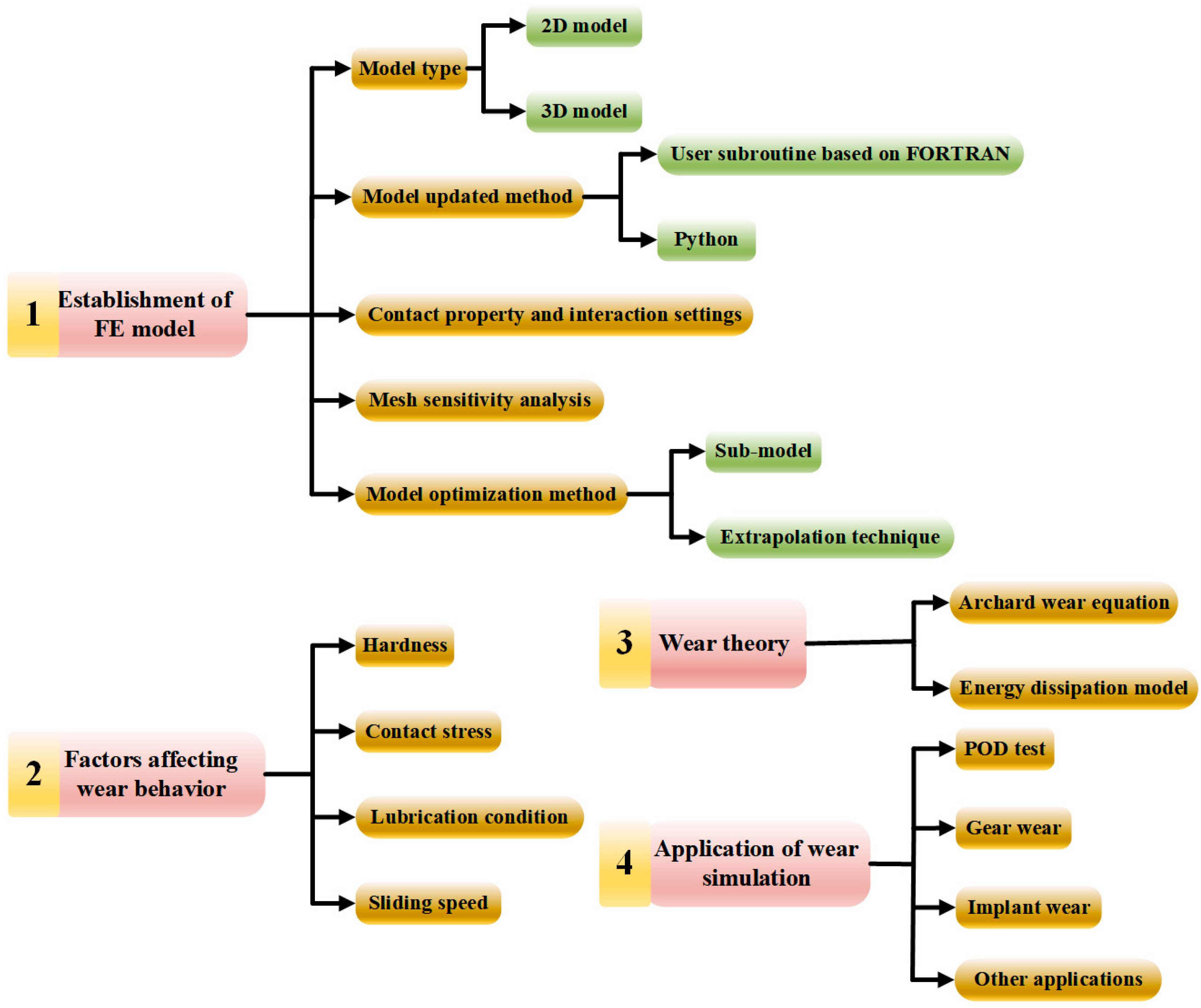
2. Finite Element Model
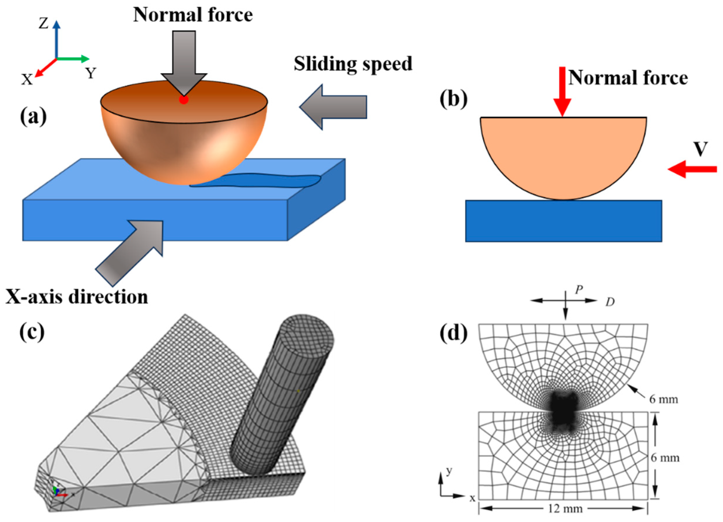
2.1. Model Type
2.1.1. 2D Model
2.1.2. 3D Model
2.2. Model Update Method
2.2.1. User Subroutine Based on FORTRAN
2.2.2. Python
2.3. Contact Property and Interaction Settings
2.4. Mesh Sensitivity Analysis
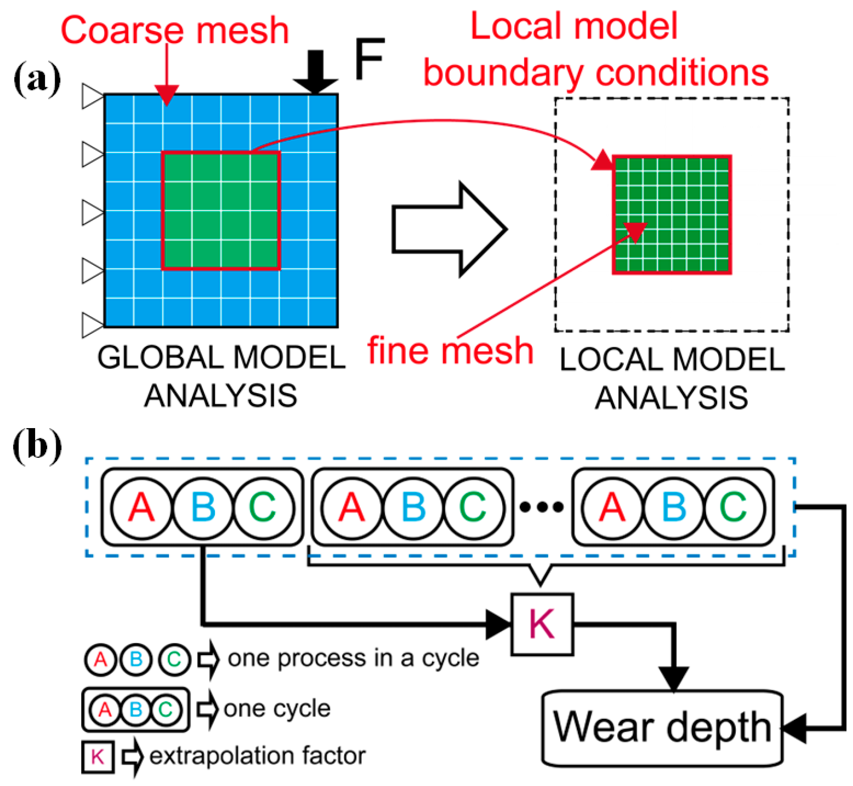
2.5. Model Optimization Method
2.5.1. Sub-Model
2.5.2. Extrapolation Technique
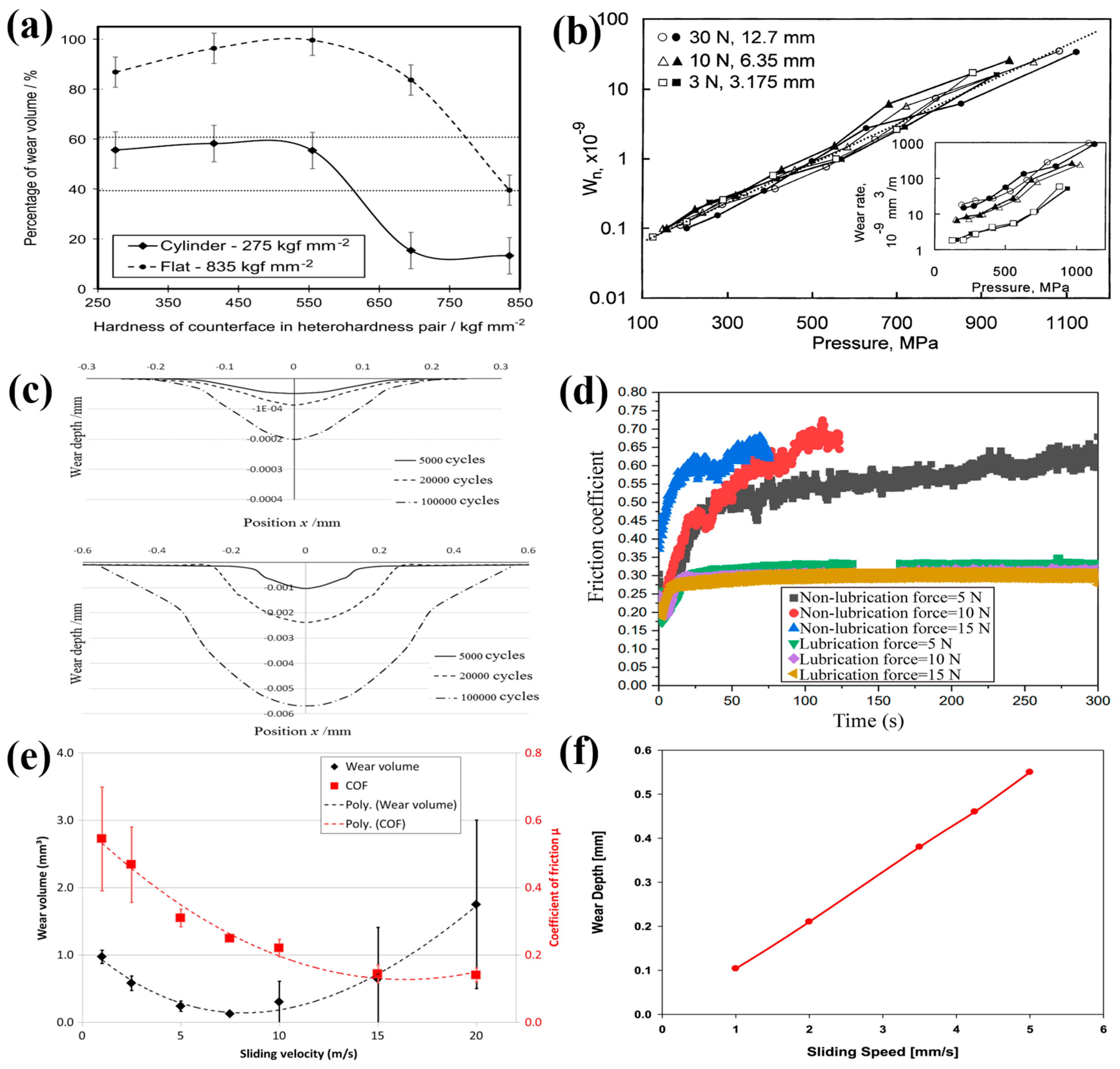
3. Factors Affecting Wear Behavior
3.1. Hardness
3.2. Contact Stress
3.3. Lubrication Condition
3.4. Sliding Speed
4. Wear Theory
4.1. Archard’s Wear Law
- Fatigue, corrosion, oxidation, and other wear mechanisms are ignored.
- The effects of temperature and lubrication on wear are not considered.
- The wear coefficient is set to constant in the simulation.
- The effect of transverse shear stress is not taken into account.
4.2. Energy Dissipation Model
5. Application of Wear Simulation
- (1)
- Using wear simulation before physical experiments allows for early assessment of wear mechanisms, enabling product optimization and reducing the need for extensive testing and improvements.
- (2)
- Compared to physical experiments, wear simulation is a cost-effective, fast, and adaptable method. It allows for multiple calculations with adjustable parameters based on real working conditions.
- (3)
- Wear simulation, compared to physical experiments, provides an intuitive visualization of the distribution of contact stress, displacement, temperature, and more, making it easier for researchers to analyze.
5.1. POD Test
5.2. Gear Wear
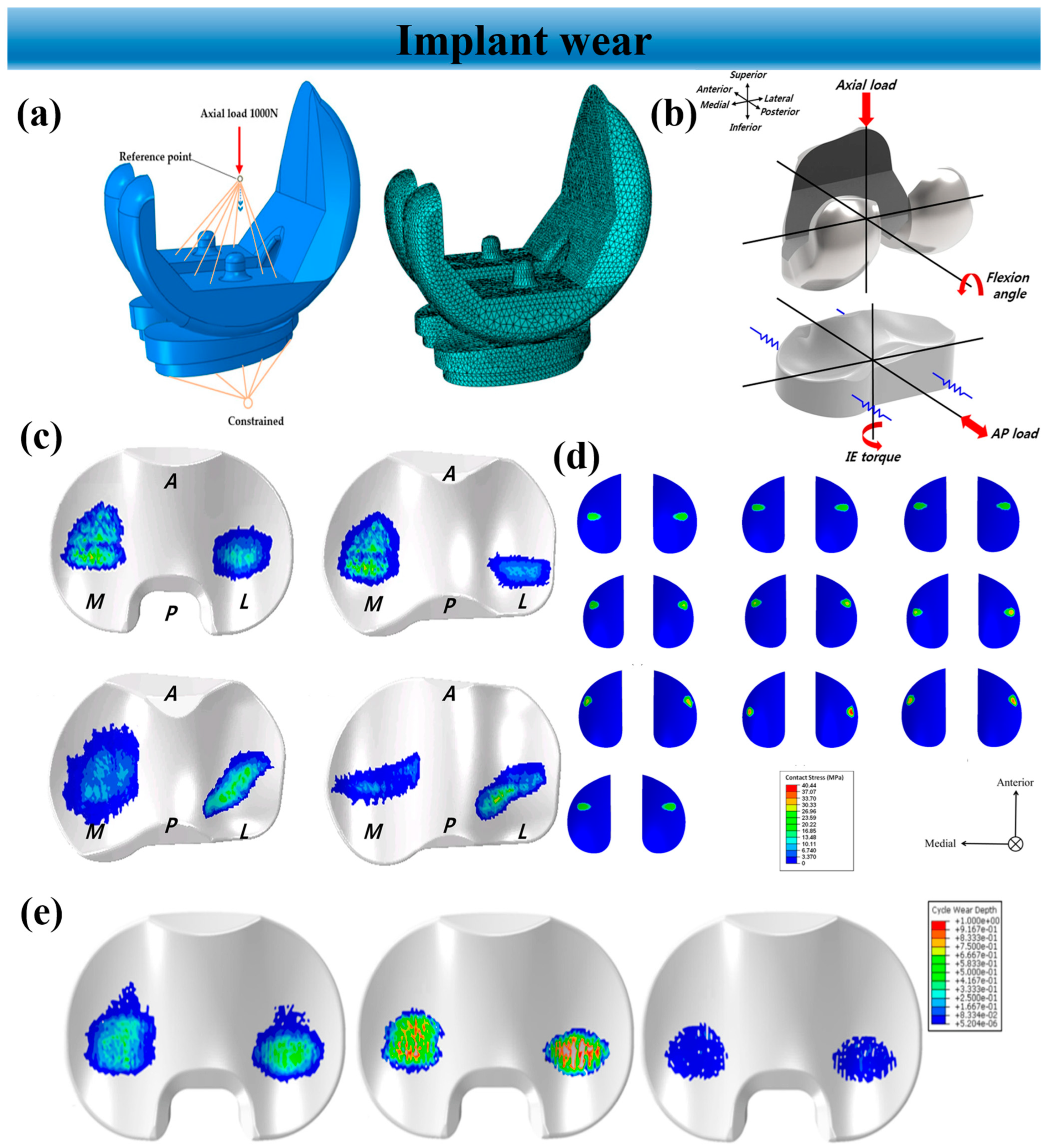
5.3. Implant Wear
5.4. Other Applications
6. Summary
- (1)
- The FE model can be categorized into two types: 2D and 3D. The 2D model is suitable for cases where there is no concern about the overall wear profile, offering high computational efficiency. On the other hand, the 3D model is used for complex structures and situations with complex boundary conditions and loading, providing more accurate computational results at the cost of higher computational resources and time.
- (2)
- To maintain contact in the model and simulate the real wear process, the model needs to be updated after each incremental step. Common methods for this include the UMESHMOTION subroutine and Python scripts. The element quality updated by the UMESHMOTION is better than what is updated by the Python script, reducing the possibility of stress concentration and convergence issues.
- (3)
- Computational efficiency is a significant concern in finite element analysis. Two commonly used methods to address this issue are the sub-model and extrapolation method. The sub-model method is often used for large and complex structures, while the extrapolation method can be applied to general wear problems, effectively improving computational efficiency. However, it is important to note that the extrapolation method requires finding an appropriate extrapolation factor to avoid significant errors. These two optimization methods can be used in combination based on actual situations.
- (4)
- There are many factors that influence wear behavior, which can be broadly categorized into two aspects: material properties and working conditions. These factors include hardness, roughness, lubrication, contact stress, sliding speed, and others. The effects of these factors on wear behavior are not singular, and they can also interact with each other. Therefore, it is challenging to propose a wear model that encompasses all influencing factors. Archard proposed a widely accepted theoretical model based on experiments, but it still has limitations. Many scholars have made improvements to Archard’s wear law through coupled analysis. In addition to this theory, the energy dissipation theory is another wear theory that is increasingly used in current wear research. Furthermore, the results obtained from the energy dissipation model show better agreement with the experimental results compared to Archard's wear law.
- (5)
- In practical applications, wear simulation technology can be utilized in various research fields, primarily focusing on predicting service life, wear profile, and wear mechanisms. This article provides an overview of the application of wear simulation in the POD test, gear wear, orthopedic implant wear, and other applications, leading to the following conclusions: Wear simulation technology can serve as an initial tool for product development and failure analysis, providing researchers with relatively reliable reference data.
- (6)
- The wear simulation presented in this paper is capable of capturing micron-scale wear processes and can provide a reasonable initial estimate of material loss. However, the subtle features of a specific wear mechanism cannot be obtained.
- (7)
- At present, the application of FEM in wear simulation is still in the research stage.
7. Perspectives
- (1)
- Development of more precise and accurate wear models to enhance the accuracy of finite element wear analysis.
- (2)
- Advancement of more efficient and accurate computational methods and algorithms to reduce computational costs and time.
- (3)
- Integration of new technologies such as machine learning to optimize and improve wear models, thereby enhancing predictive capabilities.
Funding
Data Availability Statement
Conflicts of Interest
References
- Bose, K.K.; Ramkumar, P. Finite element method based sliding wear prediction of steel-on-steel contacts using extrapolation techniques. Proc. Inst. Mech. Eng. Part J J. Eng. Tribol. 2019, 233, 1446–1463. [Google Scholar] [CrossRef]
- Gan, L.; Xiao, K.; Pu, W.; Tang, T.; Wang, J.X. A numerical method to investigate the effect of thermal and plastic behaviors on the evolution of sliding wear. Meccanica 2021, 56, 2339–2356. [Google Scholar] [CrossRef]
- Xue, Y.; Chen, J.; Guo, S.; Meng, Q.; Luo, J. Finite element simulation and experimental test of the wear behavior for self-lubricating spherical plain bearings. Friction 2018, 6, 297–306. [Google Scholar] [CrossRef]
- Llavori, I.; Zabala, A.; Mendiguren, J.; Gómez, X. A coupled 3D wear and fatigue numerical procedure: Application to fretting problems in ultra-high strength steel wires. Int. J. Fatigue 2021, 143, 106012. [Google Scholar] [CrossRef]
- Wang, X.X.; Ping, X.C.; Zeng, X.; Wang, R.J.; Zhao, Q.; Ying, S.J.; Hu, T. Fretting fatigue experiment and simulation of WC-12Co coating taking into account the wear effects. Surf. Coat. Technol. 2022, 441, 128555. [Google Scholar] [CrossRef]
- Xiang, D.D.; Yusheng, L.; Tianbiao, Y.; Di, W.; Xiaoxin, L.; Kaiming, W.; Lin, L.; Jie, P.; Yao, S.; Zibin, C. Review on wear resistance of laser cladding high-entropy alloy coatings. J. Mater. Res. Technol. 2024, 28, 911–934. [Google Scholar] [CrossRef]
- Goreham-Voss, C.M.; Hyde, P.J.; Hall, R.M.; Fisher, J.; Brown, T.D. Cross-shear implementation in sliding-distance-coupled finite element analysis of wear in metal-on-polyethylene total joint arthroplasty: Intervertebral total disc replacement as an illustrative application. J. Biomech. 2010, 43, 1674–1681. [Google Scholar] [CrossRef] [PubMed]
- Li, C.; Karimbaev, R.; Wang, S.; Amanov, A.; Wang, D.; Abdel Wahab, M. Fretting wear behavior of Inconel 718 alloy manufactured by DED and treated by UNSM. Sci. Rep.-UK 2023, 13, 1308. [Google Scholar] [CrossRef] [PubMed]
- Bose, K.K.; Ramkumar, P. Finite Element Sliding Wear Simulation of 2D Steel-on-Steel Pin-on-Disc Tribometer. Sae Tech. Pap. 2018, 28, 11. [Google Scholar] [CrossRef]
- Daves, W.; Kubin, W.; Scheriau, S.; Pletz, M. A finite element model to simulate the physical mechanisms of wear and crack initiation in wheel/rail contact. Wear 2016, 366–367, 78–83. [Google Scholar] [CrossRef]
- Shen, F.; Hu, W.; Meng, Q. A damage mechanics approach to fretting fatigue life prediction with consideration of elastic-plastic damage model and wear. Tribol. Int. 2015, 82, 176–190. [Google Scholar] [CrossRef]
- Fallahnezhad, K.; Feyzi, M.; Ghadirinejad, K.; Hashemi, R.; Taylor, M. Finite element based simulation of tribocorrosion at the head-neck junction of hip implants. Tribol. Int. 2022, 165, 107284. [Google Scholar] [CrossRef]
- Ahmadi, A.; Sadeghi, F. A Three-Dimensional Finite Element Damage Mechanics Model to Simulate Fretting Wear of Hertzian Line and Circular Contacts in Partial Slip Regime. J. Tribol. 2022, 144, 51602. [Google Scholar] [CrossRef]
- Bastola, A.; Stewart, D.; Dini, D. Three-dimensional finite element simulation and experimental validation of sliding wear. Wear 2022, 504–505, 204402. [Google Scholar] [CrossRef]
- Bae, J.W.; Lee, C.Y.; Chai, Y.S. Three dimensional fretting wear analysis by finite element substructure method. Int. J. Precis. Eng. Man. 2009, 10, 63–69. [Google Scholar] [CrossRef]
- Shu, Y.; Yang, G.; Liu, Z. Simulation research on fretting wear of train axles with interference fit based on press-fitted specimen. Wear 2023, 523, 204777. [Google Scholar] [CrossRef]
- Bose, K.K.; Penchaliah, R. 3-D FEM Wear Prediction of Brass Sliding against Bearing Steel Using Constant Contact Pressure Approximation Technique. Tribol. Online 2019, 14, 194–207. [Google Scholar] [CrossRef]
- Zuo, S.G.; Ni, T.X.; Wu, X.D.; Wu, K.; Yang, X.W. Prediction procedure for wear distribution of transient rolling tire. Int. J. Automot. Technol. 2014, 15, 505–515. [Google Scholar] [CrossRef]
- Yu, H.; Lian, Z.; Lin, T.; Liu, Y.; Xu, X. Experimental and numerical study on casing wear in highly deviated drilling for oil and gas. Adv. Mech. Eng. 2016, 8, 2071834741. [Google Scholar] [CrossRef]
- McColl, I.R.; Ding, J.; Leen, S.B. Finite element simulation and experimental validation of fretting wear. Wear 2004, 256, 1114–1127. [Google Scholar] [CrossRef]
- Fallahnezhad, K.; Oskouei, R.H.; Taylor, M. Development of a fretting corrosion model for metallic interfaces using adaptive finite element analysis. Finite Elem. Anal. Des. 2018, 148, 38–47. [Google Scholar] [CrossRef]
- Bevill, S.L.; Bevill, G.R.; Penmetsa, J.R.; Petrella, A.J.; Rullkoetter, P.J. Finite element simulation of early creep and wear in total hip arthroplasty. J. Biomech. 2005, 38, 2365–2374. [Google Scholar] [CrossRef] [PubMed]
- Knight, L.A.; Pal, S.; Coleman, J.C.; Bronson, F.; Haider, H.; Levine, D.L.; Taylor, M.; Rullkoetter, P.J. Comparison of long-term numerical and experimental total knee replacement wear during simulated gait loading. J. Biomech. 2007, 40, 1550–1558. [Google Scholar] [CrossRef] [PubMed]
- Peng, R.T.; Li, J.; Tang, X.Z.; Zhou, Z. Simulation of Tool Wear in Prestressed Cutting Superalloys. Mater. Sci. Forum 2016, 836–837, 402–407. [Google Scholar] [CrossRef]
- Albers, A.; Reichert, S. On the influence of surface roughness on the wear behavior in the running-in phase in mixed-lubricated contacts with the finite element method. Wear 2017, 376–377, 1185–1193. [Google Scholar] [CrossRef]
- Shankar, S.; Nithyaprakash, R.; Santhosh, B.R.; Uddin, M.S.; Pramanik, A. Finite element submodeling technique to analyze the contact pressure and wear of hard bearing couples in hip prosthesis. Comput. Methods Biomech. Biomed. Eng. 2020, 23, 422–431. [Google Scholar] [CrossRef]
- Shankar, S.; Nithyaprakash, R.; Santhosh, B.R.; Gur, A.K.; Pramanik, A. Experimental and submodeling technique to investigate the wear of silicon nitride against Ti6Al4V alloy with bio-lubricants for various gait activities. Tribol. Int. 2020, 151, 106529. [Google Scholar] [CrossRef]
- Nitish Prasad, K.; Ramkumar, P. FEM wear prediction of ceramic hip replacement bearings under dynamic edge loading conditions. J. Mech. Behav. Biomed. 2023, 146, 106049. [Google Scholar] [CrossRef]
- Mukras, S.; Kim, N.H.; Sawyer, W.G.; Jackson, D.B.; Bergquist, L.W. Numerical integration schemes and parallel computation for wear prediction using finite element method. Wear 2009, 266, 822–831. [Google Scholar] [CrossRef]
- Bortoleto, E.M.; Rovani, A.C.; Seriacopi, V.; Profito, F.J.; Zachariadis, D.C.; Machado, I.F.; Sinatora, A.; Souza, R.M. Experimental and numerical analysis of dry contact in the pin on disc test. Wear 2013, 301, 19–26. [Google Scholar] [CrossRef]
- Schmidt, A.A.; Schmidt, T.; Grabherr, O.; Bartel, D. Transient wear simulation based on three-dimensional finite element analysis for a dry running tilted shaft-bushing bearing. Wear 2018, 408–409, 171–179. [Google Scholar] [CrossRef]
- Arunachalam, A.P.S.; Idapalapati, S. Material removal analysis for compliant polishing tool using adaptive meshing technique and Archard wear model. Wear 2019, 418–419, 140–150. [Google Scholar] [CrossRef]
- Joshi, V.; Ramkumar, P. Transient Wear FEA Modelling Using Extrapolation Technique for Steel-on-Steel Dry Sliding Contact. Tribol. Online 2022, 17, 162–174. [Google Scholar] [CrossRef]
- Zhang, F.; Peng, X. Analysis on load-bearing contact characteristics of face gear tooth surface wear. For. Chem. Rev. 2022, 743–754. Available online: http://forestchemicalsreview.com/index.php/JFCR/article/view/1164 (accessed on 25 December 2023).
- Martínez-Londoño, J.C.; Martínez-Trinidad, J.; Hernández-Fernández, A.; García-León, R.A. Finite Element Analysis on AISI 316L Stainless Steel Exposed to Ball-on-Flat Dry Sliding Wear Test. Trans. Indian Inst. Met. 2023, 76, 97–106. [Google Scholar] [CrossRef]
- Li, L.; Kang, L.; Ma, S.; Li, Z.; Ruan, X.; Cai, A. Finite element analysis of fretting wear considering variable coefficient of friction. Proc. Inst. Mech. Eng. Part J J. Eng. Tribol. 2019, 233, 758–768. [Google Scholar] [CrossRef]
- Zhang, M.; Zeng, D.; Lu, L.; Zhang, Y.; Wang, J.; Xu, J. Finite element modelling and experimental validation of bolt loosening due to thread wear under transverse cyclic loading. Eng. Fail. Anal. 2019, 104, 341–353. [Google Scholar] [CrossRef]
- Tandler, R.; Bohn, N.; Gabbert, U.; Woschke, E. Analytical wear model and its application for the wear simulation in automotive bush chain drive systems. Wear 2020, 446–447, 203193. [Google Scholar] [CrossRef]
- Imran, M.; Wang, D.; Abdel Wahab, M. Three-dimensional finite element simulations of fretting wear in steel wires used in coal mine hoisting system. Adv. Eng. Softw. 2023, 184, 103499. [Google Scholar] [CrossRef]
- Yue, T.; Abdel Wahab, M. Finite element analysis of fretting wear under variable coefficient of friction and different contact regimes. Tribol. Int. 2017, 107, 274–282. [Google Scholar] [CrossRef]
- Hegadekatte, V.; Huber, N.; Kraft, O. Modeling and simulation of wear in a pin on disc tribometer. Tribol. Lett. 2006, 24, 51–60. [Google Scholar] [CrossRef]
- ABAQUS Inc. ABAQUS Analysis User’s Manual; Dassault Systèmes: Providence, RI, USA, 2017; Available online: https://help.3ds.com/HelpDS.aspx?V=2017&P=DSSIMULIA_Established&L=English&contextscope=all&F=SIMULIA_Established_FrontmatterMap/DSDocAbaqus.htm (accessed on 25 December 2023).
- Li, H.; Ren, Z.; Su, X.; Shen, L.; Huang, J. Study on the Fretting Wear Evolution Model of Wires with Curvature Inside Metal Rubber. Tribol. Lett. 2023, 71, 22. [Google Scholar] [CrossRef]
- Zhang, Y.; Wei, F.; Lin, S.; Sun, X.; Liu, L. Study on the Performance of Reciprocating Seals under the Coupling Effect of Elastohydrodynamic Lubrication and Rubber Wear. Eng. Res. Express 2024, 6, 015064. [Google Scholar] [CrossRef]
- Zhang, S.; Liu, Y.; Zhou, H.; Zhang, W.; Chen, Y.; Zhu, H. Analysis of the Effect of Wear on Tire Cornering Characteristics Based on Grounding Characteristics. World Electr. Veh. J. 2023, 14, 166. [Google Scholar] [CrossRef]
- Liu, Y.; Xiang, D.; Wang, K.; Yu, T. Corrosion of Laser Cladding High-Entropy Alloy Coatings: A Review. Coatings 2022, 12, 1669. [Google Scholar] [CrossRef]
- Xiang, D.; Wang, D.; Zheng, T.; Chen, Y. Effects of Rare Earths on Microstructure and Wear Resistance in Metal Additive Manufacturing: A Review. Coatings 2024, 14, 139. [Google Scholar] [CrossRef]
- Wang, K.; Liu, W.; Li, X.; Tong, Y.; Hu, Y.; Hu, H.; Chang, B.; Ju, J. Effect of hot isostatic pressing on microstructure and properties of high chromium K648 superalloy manufacturing by extreme high-speed laser metal deposition. J. Mater. Res. Technol. 2024, 28, 3951–3959. [Google Scholar] [CrossRef]
- Li, S.; Wang, L.; Yang, G. Unified computational model of thermochemical erosion and mechanical wear in artillery barrel considering hydrodynamic friction. Numer. Heat Transfer. Part A Appl. 2023, 1–21. [Google Scholar] [CrossRef]
- Shu, L.; Hashimoto, S.; Sugita, N. Enhanced In-Silico Polyethylene Wear Simulation of Total Knee Replacements During Daily Activities. Ann. Biomed. Eng. 2021, 49, 322–333. [Google Scholar] [CrossRef]
- Saini, V.; Maurya, U.; Thakre, G.D. Estimating the Dry-Wear Behavior of Rolling/Sliding Bearings (PB, Gunmetal, and Al6061)Tribo Materials. J. Fail. Anal. Prev. 2023, 23, 2439–2451. [Google Scholar] [CrossRef]
- Curreli, C.; Viceconti, M.; Di Puccio, F. Submodeling in wear predictive finite element models with multipoint contacts. Int. J. Numer. Meth. Eng. 2021, 122, 3812–3823. [Google Scholar] [CrossRef]
- Curreli, C.; Di Puccio, F.; Mattei, L. Application of the finite element submodeling technique in a single point contact and wear problem. Int. J. Numer. Meth. Eng. 2018, 116, 708–722. [Google Scholar] [CrossRef]
- Rigney, D.A. Colmments on the sliding wear of metals. Tribol. Int. 1997, 30, 361–367. [Google Scholar] [CrossRef]
- Lemm, J.D.; Warmuth, A.R.; Pearson, S.R.; Shipway, P.H. The influence of surface hardness on the fretting wear of steel pairs—Its role in debris retention in the contact. Tribol. Int. 2015, 81, 258–266. [Google Scholar] [CrossRef]
- Ravikiran, A.; Jahanmir, S. Effect of contact pressure and load on wear of alumina. Wear 2001, 251, 980–984. [Google Scholar] [CrossRef]
- Qin, W.; Wang, M.; Sun, W.; Shipway, P.; Li, X. Modeling the effectiveness of oil lubrication in reducing both friction and wear in a fretting contact. Wear 2019, 426–427, 770–777. [Google Scholar] [CrossRef]
- Cao, G.; Zhang, J.; Guo, Y.; Liu, C.; Micheal, M.; Lv, C.; Yu, H.; Wu, H. Numerical modeling on friction and wear behaviors of all-metal progressive cavity pump. J. Petrol. Sci. Eng. 2022, 213, 110443. [Google Scholar] [CrossRef]
- Khader, I.; Renz, A.; Kailer, A. A wear model for silicon nitride in dry sliding contact against a nickel-base alloy. Wear 2017, 376–377, 352–362. [Google Scholar] [CrossRef]
- Arjmandi, M.; Ramezani, M.; Giordano, M.; Schmid, S. Finite element modelling of sliding wear in three-dimensional woven textiles. Tribol. Int. 2017, 115, 452–460. [Google Scholar] [CrossRef]
- Guo, J.; Li, D.; Wang, H.; Yang, Y.; Wang, L.; Guan, D.; Qiu, Y.; He, L.; Zhang, S. Effect of contact stress on the cycle-dependent wear behavior of ceramic restoration. J. Mech. Behav. Biomed. 2017, 68, 16–25. [Google Scholar] [CrossRef] [PubMed]
- Liu, H.; Liu, H.; Zhu, C.; Parker, R.G. Effects of lubrication on gear performance: A review. Mech. Mach. Theory 2020, 145, 103701. [Google Scholar] [CrossRef]
- Zhao, J.; Sheng, W.; Li, Z.; Zhang, H.; Zhu, R. Effect of lubricant selection on the wear characteristics of spur gear under oil-air mixed lubrication. Tribol. Int. 2022, 167, 107382. [Google Scholar] [CrossRef]
- Okonkwo, P.C.; Kelly, G.; Rolfe, B.F.; Pereira, M.P. The effect of sliding speed on the wear of steel-tool steel pairs. Tribol. Int. 2016, 97, 218–227. [Google Scholar] [CrossRef]
- Chowdhury, M.A.; Khalil, M.K.; Nuruzzaman, D.M.; Rahaman, M.L. The Effect of Sliding Speed and Normal Load on Friction and Wear Property of Aluminum. Int. J. Mech. Mechatron. Eng. 2011, 11, 45–49. [Google Scholar]
- Meng, H.C.; Ludema, K.C. Wear models and predictive equations: Their form and content. Wear 1995, 181–183, 443–457. [Google Scholar] [CrossRef]
- Feyzi, M.; Fallahnezhad, K.; Taylor, M.; Hashemi, R. A review on the finite element simulation of fretting wear and corrosion in the taper junction of hip replacement implants. Comput. Biol. Med. 2021, 130, 104196. [Google Scholar] [CrossRef] [PubMed]
- Archard, J.F. Contact and Rubbing of Flat Surfaces. J. Appl. Phys. 1953, 24, 981–988. [Google Scholar] [CrossRef]
- Fouvry, S.; Arnaud, P.; Mignot, A.; Neubauer, P. Contact size, frequency and cyclic normal force effects on Ti-6Al-4V fretting wear processes: An approach combining friction power and contact oxygenation. Tribol. Int. 2017, 113, 460–473. [Google Scholar] [CrossRef]
- Fallahnezhad, K.; Oskouei, R.H.; Badnava, H.; Taylor, M. An adaptive finite element simulation of fretting wear damage at the head-neck taper junction of total hip replacement: The role of taper angle mismatch. J. Mech. Behav. Biomed. 2017, 75, 58–67. [Google Scholar] [CrossRef] [PubMed]
- Zhang, T.; Harrison, N.M.; McDonnell, P.F.; McHugh, P.E.; Leen, S.B. A finite element methodology for wear–fatigue analysis for modular hip implants. Tribol. Int. 2013, 65, 113–127. [Google Scholar] [CrossRef]
- Mohd Tobi, A.L.; Shipway, P.H.; Leen, S.B. Gross slip fretting wear performance of a layered thin W-DLC coating: Damage mechanisms and life modelling. Wear 2011, 271, 1572–1584. [Google Scholar] [CrossRef]
- Rezaei, A.; Van Paepegem, W.; De Baets, P.; Ost, W.; Degrieck, J. Adaptive finite element simulation of wear evolution in radial sliding bearings. Wear 2012, 296, 660–671. [Google Scholar] [CrossRef]
- Shen, X.; Liu, Y.; Cao, L.; Chen, X. Numerical Simulation of Sliding Wear for Self-lubricating Spherical Plain Bearings. J. Mater. Res. Technol. 2012, 1, 8–12. [Google Scholar] [CrossRef]
- Shu, Y.J.; Shen, F.; Ke, L.L.; Wang, Y.S. Adaptive finite element simulation and experimental verification for fretting wear of PVDF piezoelectric thin films. Wear 2022, 502, 204395. [Google Scholar] [CrossRef]
- Zao, H.; Yumei, H.; Xingyuan, Z.; Yuanyuan, Y. A Calculation Method for Tooth Wear Depth Based on the Finite Element Method That Considers the Dynamic Mesh Force. Machines 2022, 10, 69. [Google Scholar]
- Põdra, P.; Andersson, S. Wear simulation with the Winkler surface model. Wear 1997, 207, 79–85. [Google Scholar] [CrossRef]
- Suh, N.P. The delamination theory of wear. Wear 1973, 25, 111–124. [Google Scholar] [CrossRef]
- Sobis, T.; Engel, U.; Geiger, M. A theoretical study on wear simulation in metal forming processes. J. Mater. Process. Technol. 1992, 34, 233–240. [Google Scholar] [CrossRef]
- Cheng, Q.; Zhang, H.; Zhang, T.; Li, Y.; Xu, J.; Liu, Z. Prediction method of precision deterioration of rolling guide under multi-random parameters based on frictional thermal expansion effect. Tribol. Int. 2023, 189, 108883. [Google Scholar] [CrossRef]
- Gui, L.; Wang, X.; Fan, Z.; Zhang, F. A simulation method of thermo-mechanical and tribological coupled analysis in dry sliding systems. Tribol. Int. 2016, 103, 121–131. [Google Scholar] [CrossRef]
- Luo, S.; Zhu, D.; Hua, L.; Qian, D.; Yan, S. Numerical analysis of die wear characteristics in hot forging of titanium alloy turbine blade. Int. J. Mech. Sci. 2017, 123, 260–270. [Google Scholar] [CrossRef]
- Yin, J.; Lu, C.; Mo, J. Comprehensive modeling strategy for thermomechanical tribological behavior analysis of railway vehicle disc brake system. Friction 2024, 12, 74–94. [Google Scholar] [CrossRef]
- Wang, A. A unified theory of wear for ultra-high molecular weight polyethylene in multi-directional sliding. Wear 2001, 248, 38–47. [Google Scholar] [CrossRef]
- Kang, L.; Galvin, A.L.; Brown, T.D.; Jin, Z.; Fisher, J. Quantification of the effect of cross-shear on the wear of conventional and highly cross-linked UHMWPE. J. Biomech. 2008, 41, 340–346. [Google Scholar] [CrossRef] [PubMed]
- Kang, L.; Galvin, A.L.; Fisher, J.; Jin, Z. Enhanced computational prediction of polyethylene wear in hip joints by incorporating cross-shear and contact pressure in additional to load and sliding distance: Effect of head diameter. J. Biomech. 2009, 42, 912–918. [Google Scholar] [CrossRef]
- Fouvry, S.; Liskiewicz, T.; Kapsa, P.; Hannel, S.; Sauger, E. An energy description of wear mechanisms and its applications to oscillating sliding contacts. Wear 2003, 255, 287–298. [Google Scholar] [CrossRef]
- Xie, L.; Guan, Y.; Lu, J.; Zhu, P.; Chen, R.; Lin, H. Fretting wear behavior test and numerical simulation of Inconel 690 alloy. J. Nucl. Sci. Technol. 2023, 60, 1100–1115. [Google Scholar] [CrossRef]
- Xue, X.; Liu, J.; Jia, J.; Yang, S.; Li, Y. Simulation and Verification of Involute Spline Tooth Surface Wear before and after Carburizing Based on Energy Dissipation Method. Machines 2023, 11, 78. [Google Scholar] [CrossRef]
- Zhang, C.; Shen, F.; Ke, L. Electrical contact resistance endurance of AgNi10 alloy under fretting wear: Experiment and numerical prediction. Wear 2023, 530–531, 205009. [Google Scholar] [CrossRef]
- Hwang, S.; Lee, N.; Kim, N. Experiment and Numerical Study of Wear in Cross Roller Thrust Bearings. Lubricants 2015, 3, 447–458. [Google Scholar] [CrossRef]
- Li, H.; Ren, Z.; Huang, J.; Zhong, S. Fretting wear evolution model of the metal filaments inside metal rubber. Wear 2022, 506–507, 204438. [Google Scholar] [CrossRef]
- Zhang, Z.; Zhao, G.; Yuan, Y.; Zhang, H.; Wu, Y. Finite Element Simulation and Fretting Wear Prediction of a Tenon Connection Structure. Lubricants 2023, 11, 421. [Google Scholar] [CrossRef]
- Tkaya, M.B.; Mezlini, S.; Mansori, M.E.; Zahouani, H. On some tribological effects of graphite nodules in wear mechanism of SG cast iron: Finite element and experimental analysis. Wear 2009, 267, 535–539. [Google Scholar] [CrossRef]
- Banijamali, S.M.; Shariat Razavi, M.; Palizdar, Y.; Najafi, S.; Sheikhani, A.; Torkamani, H. Experimental and Simulation Study on Wear Behavior of ZK60 Alloy with 3 wt.% Yttrium Addition. J. Mater. Eng. Perform. 2022, 31, 4721–4734. [Google Scholar] [CrossRef]
- Li, H.; Zhao, Y.; Jiang, J.; Wang, H.; He, J.; Liu, J.; Peng, J.; Zhu, M. Effect of frequency on the fatigue performance of bolted joints under axial excitation. Tribol. Int. 2022, 176, 107933. [Google Scholar] [CrossRef]
- Li, L.; Li, G.; Wang, J.; Fan, C.; Cai, A. Fretting Wear Mechanical Analysis of Double Rough Surfaces Based on Energy Method. Proc. Inst. Mech. Eng. Part J J. Eng. Tribol. 2023, 237, 356–368. [Google Scholar] [CrossRef]
- Zhang, T.; McHugh, P.E.; Leen, S.B. Computational study on the effect of contact geometry on fretting behaviour. Wear 2011, 271, 1462–1480. [Google Scholar] [CrossRef]
- Cai, M.; Zhang, P.; Xiong, Q.; Cai, Z.; Luo, S.; Gu, L.; Zeng, L. Finite element simulation of fretting wear behaviors under the ball-on-flat contact configuration. Tribol. Int. 2023, 177, 107930. [Google Scholar] [CrossRef]
- Dong, P.; Yang, Z.; Na, L.; Xinggui, W. The wear life prediction method of gear system. J. Harbin Inst. Technol. 2012, 44, 29–33, 39. [Google Scholar]
- Janakiraman, V.; Li, S.; Kahraman, A. An Investigation of the Impacts of Contact Parameters on Wear Coefficient. J. Tribol. 2014, 136, 31602. [Google Scholar] [CrossRef]
- Osman, T.; Velex, P. Static and dynamic simulations of mild abrasive wear in wide-faced solid spur and helical gears. Mech. Mach. Theory 2010, 45, 911–924. [Google Scholar] [CrossRef]
- Xue, X.; Huo, Q.; Hong, L. Fretting Wear-Fatigue Life Prediction for Aero-Engine’s Involute Spline Couplings Based on Abaqus. J. Aerospace Eng. 2019, 32, 4019081. [Google Scholar] [CrossRef]
- Zhang, B.; Liu, H.; Zhu, C.; Ge, Y. Simulation of the fatigue-wear coupling mechanism of an aviation gear. Friction 2021, 9, 1616–1634. [Google Scholar] [CrossRef]
- Feng, K.; Borghesani, P.; Smith, W.A.; Randall, R.B.; Chin, Z.Y.; Ren, J.; Peng, Z. Vibration-based updating of wear prediction for spur gears. Wear 2019, 426–427, 1410–1415. [Google Scholar] [CrossRef]
- Liu, X.; Yang, Y.; Zhang, J. Investigation on coupling effects between surface wear and dynamics in a spur gear system. Tribol. Int. 2016, 101, 383–394. [Google Scholar] [CrossRef]
- Changjiang, Z.; Yuying, L.; Hongbing, W.; Xu, H. Adhesive Wear Models for Helical Gears under Quasi-static and Dynamic Loads. Chin. J. Mech. Eng.-En. 2018, 54, 10–22. [Google Scholar] [CrossRef]
- Sun, Y.; Li, Y.; Zhang, Q.; Qin, X.; Chen, K. Wear analysis and simulation of small module gear based on Archard model. Eng. Fail. Anal. 2023, 144, 106990. [Google Scholar] [CrossRef]
- Chao, L.; Peitang, W.; Caichao, Z. Tooth contact analysis of helical beveloid gear with parallel axis. J. Chongqing Univ. (Nat. Sci. Ed.) 2012, 35, 1–6. [Google Scholar]
- Jin, S.; Chen, H.; Li, Z.; Lai, X. A small displacement torsor model for 3D tolerance analysis of conical structures. Proc. Inst. Mech. Eng. Part C J. Mech. Eng. Sci. 2015, 229, 2514–2523. [Google Scholar] [CrossRef]
- Xu, R.; Huang, K.; Guo, J.; Yang, L.; Qiu, M.; Ru, Y. Gear-tolerance optimization based on a response surface method. Trans. Can. Soc. Mech. Eng. 2018, 42, 309–322. [Google Scholar] [CrossRef]
- Teoh, S.H.; Chan, W.H.; Thampuran, R. An elasto-plastic finite element model for polyethylene wear in total hip arthroplasty. J. Biomech. 2002, 35, 323–330. [Google Scholar] [CrossRef] [PubMed]
- Uddin, M.S.; Zhang, L.C. Predicting the wear of hard-on-hard hip joint prostheses. Wear 2013, 301, 192–200. [Google Scholar] [CrossRef]
- Xiang, D.; Cui, Y.; Wan, Z.; Wang, S.; Peng, L.; Liao, Z.; Chen, C.; Liu, W. Study on swelling, compression property and degradation stability of PVA composite hydrogels for artificial nucleus pulposus. J. Mech. Behav. Biomed. 2022, 136, 105496. [Google Scholar] [CrossRef]
- Xiang, D.; Tan, X.; Sui, X.; He, J.; Chen, C.; Hao, J.; Liao, Z.; Liu, W. Comparative study on microstructure, bio-tribological behavior and cytocompatibility of Cr-doped amorphous carbon films for Co-Cr-Mo artificial lumbar disc. Tribol. Int. 2021, 155, 106760. [Google Scholar] [CrossRef]
- Innocenti, B.; Labey, L.; Kamali, A.; Pascale, W.; Pianigiani, S. Development and Validation of a Wear Model to Predict Polyethylene Wear in a Total Knee Arthroplasty: A Finite Element Analysis. Lubricants 2014, 2, 193–205. [Google Scholar] [CrossRef]
- Zhang, J.; Chen, Z.; Gao, Y.; Zhang, X.; Guo, L.; Jin, Z. Computational Wear Prediction for Impact of Kinematics Boundary Conditions on Wear of Total Knee Replacement Using Two Cross-Shear Models. J. Tribol. 2019, 141, 111201. [Google Scholar] [CrossRef]
- Kang, K.; Son, J.; Kim, H.; Baek, C.; Kwon, O.; Koh, Y. Wear predictions for UHMWPE material with various surface properties used on the femoral component in total knee arthroplasty: A computational simulation study. J. Mater. Sci. Mater. Med. 2017, 28, 105. [Google Scholar] [CrossRef]
- Koh, Y.; Jung, K.; Hong, H.; Kim, K.; Kang, K. Optimal Design of Patient-Specific Total Knee Arthroplasty for Improvement in Wear Performance. J. Clin. Med. 2019, 8, 2023. [Google Scholar] [CrossRef]
- Mohd Mukhtar, N.Q.; Shuib, S.; Anuar, M.A.; Mohd Miswan, M.F.; Mohd Anuar, M.A. Design Optimisation of Bi-Cruciate Retaining Total Knee Arthroplasty (TKA) Prosthesis via Taguchi Methods. Mathematics 2023, 11, 312. [Google Scholar] [CrossRef]
- Koh, Y.; Park, K.; Lee, H.; Park, J.; Kang, K. Prediction of wear performance in femoral and tibial conformity in patient-specific cruciate-retaining total knee arthroplasty. J. Orthop. Surg. Res. 2020, 15, 24. [Google Scholar] [CrossRef]
- Koh, Y.; Lee, J.; Kang, K. Prediction of Wear on Tibial Inserts Made of UHMWPE, PEEK, and CFR-PEEK in Total Knee Arthroplasty Using Finite-Element Analysis. Lubricants 2019, 7, 30. [Google Scholar] [CrossRef]
- Huang, T.C.; Tsai, J.W.; Liao, K.C. Wear and leakage assessments of canted coil Spring-Energized polytetrafluoroethylene seals under Ultra-High cycle operations. Eng. Fail. Anal. 2022, 135, 106110. [Google Scholar] [CrossRef]
- Cao, W.; Chang, Z.; Zhou, A.; Dou, X.; Gao, G.; Gong, J. Investigation into the Influence of Parallel Offset Wear on Stirling Engine Piston Rod Oil-Free Lubrication Seal. Machines 2022, 10, 350. [Google Scholar] [CrossRef]
- Wang, H.; Liu, T.; Zhang, Y.; Zhu, Y.; Liu, F.; Wang, T. A Fully Coupled Tribocorrosion Simulation Method for Anchor Chain Considering Mechano-Electrochemical Interaction. Lubricants 2022, 10, 330. [Google Scholar] [CrossRef]
- Li, R.; Sun, Y.; Yu, Y.; Tian, G. Finite Element Analysis for Tread Wear of Radial Tire. In Proceedings of the 2022 5th International Conference on Mechatronics, Robotics and Automation (ICMRA), Wuhan, China, 25–27 November 2022; pp. 101–106. [Google Scholar]
- Dai, X.; Li, J. Simulation Analysis of Cam Wear in Shedding Mechanism of Loom. J. Physics. Conf. Ser. 2021, 1995, 12020. [Google Scholar] [CrossRef]
- Jin, Y.; Zou, L.; Huang, J.; Jiang, X.; Guo, Z.; Xie, J.; Yuan, Z. Numerical research on ablation and wear of the artillery barrel based on UMESHMOTION user-defined subroutine. Eng. Rep. 2023, 5, e12575. [Google Scholar] [CrossRef]
- Lu, L.; Xu, Y.; Li, M.; Xue, Q.; Zhang, M.; Liu, L.; Wu, Z. Analysis of fretting wear behavior of unloading valve of gasoline direct injection high pressure pump. J. Zhejiang Univ.-Sci. A 2022, 23, 314–328. [Google Scholar] [CrossRef]
- Li, L.; Zhang, W.; Li, G.; Wang, J.; Li, L.; Xie, M. Simulation Study of Thermal-Mechanical Coupling Fretting Wear of Ti-6Al-4V Alloy. Appl. Sci. 2022, 12, 7400. [Google Scholar] [CrossRef]


| References | Model Type | Model Updating Method | Wear Theory | Model Optimization Method | Application |
|---|---|---|---|---|---|
| [8] | 2D | UMESHMOTION | Energy dissipation model | Extrapolation technique | Fretting wear |
| [9] | 2D | UMESHMOTION | Archard’s wear law | Extrapolation technique | Service life prediction |
| [10] | 2D/3D | Nope | Nope | Sub-model | Wear profile prediction |
| [11] | 2D | UMESHMOTION | Energy dissipation model + Damage-coupled elastic–plastic constitutive model | Extrapolation technique | Service life prediction |
| [12] | 3D | UMESHMOTION | Archard’s wear law | Extrapolation technique | Tribocorrosion |
| [13] | 3D | Nope | Energy dissipation model | Nope | Wear mechanism auxiliary analysis |
| [14] | 3D | UMESHMOTION | Archard’s wear law | Extrapolation technique | Wear profile prediction |
| [15] | 3D | UMESHMOTION | Archard’s wear law | Sub-model | Fretting wear |
| [16] | 3D | UMESHMOTION | Energy dissipation model | Extrapolation technique | Fretting wear |
| [17] | 3D | UMESHMOTION | Archard’s wear law | Extrapolation technique | POD tribometer wear prediction |
| [18] | 3D | UMESHMOTION | Archard’s wear law | Extrapolation technique | Tire tread wear |
| [19] | 2D | UMESHMOTION | Archard’s wear law | Nope | Casing wear |
| [20] | 2D | UMESHMOTION | Archard’s wear law | Mesh and increment size optimization | Fretting wear |
| [2] | 3D | UMESHMOTION | Power hardening law +Archard’s wear law | Extrapolation technique | Thermo-mechanical wear |
| [21] | 3D | UMESHMOTION | Electrochemical equation + Archard’s wear law | Nope | Corrosive wear |
| [22] | 3D | Python | Archard’s wear law | Nope | Orthopedic implant wear |
| [23] | 3D | Python | Archard’s wear law | Nope | Orthopedic implant wear |
| [24] | 2D/3D | Python | Usui’s tool wear model | Nope | Tool wear |
| [25] | 3D | Python | Archard’s wear law | Extrapolation technique | POD tribometer wear prediction |
| [26,27] | 3D | UMESHMOTION | Archard’s wear law | Sub-model | Orthopedic implant wear |
| [28] | 3D | UMESHMOTION | Archard’s wear law | Sub-model | Orthopedic implant wear |
| [29] | 2D | UMESHMOTION | Archard’s wear law | Extrapolation technique | Pin wear prediction |
| [30] | 3D | UMESHMOTION | Archard’s wear law | Extrapolation technique | POD tribometer wear prediction |
| [31] | 3D | UMESHMOTION | Archard’s wear law | Extrapolation technique | Dry sliding wear prediction |
| [1] | 2D | UMESHMOTION | Archard’s wear law | Extrapolation technique | POD tribometer wear prediction |
| [32] | 3D | UMESHMOTION | Archard’s wear law | Nope | Wear profile prediction |
| [33] | 2D | UMESHMOTION | Archard’s wear law | Extrapolation technique | POD tribometer wear prediction |
| [34] | 3D | UMESHMOTION | Archard’s wear law | Nope | Gear wear prediction |
| [35] | 3D | UMESHMOTION | Archard’s wear law + shape functions and Newton–Raphson formulation | Nope | POD tribometer wear prediction |
| [36] | 2D | UMESHMOTION | Energy dissipation model | Nope | Fretting wear |
| [37] | 3D | UMESHMOTION | Energy dissipation model | Nope | Wear profile evolution |
| [38] | 3D | UMESHMOTION | Energy dissipation model | Extrapolation technique | Wear simulation in automotive bush chain |
| [39] | 3D | UMESHMOTION | Energy dissipation model | Extrapolation technique | Fretting wear |
| Reference | Application Field | Year | Aim |
|---|---|---|---|
| [90] | Service life prediction | 2023 | The study proposed an approach based on FEM to predict the electrical contact resistance endurance of AgNi10 alloy. |
| [91] | Service life prediction | 2015 | The study predicted thrust bearing run-out, with the intention of using linear and non-linear wear models to predict bearing failure/life. |
| [4] | Service life prediction | 2021 | The study introduced a combined 3D wear and fatigue numerical method for fretting issues in ultra-high-strength steel wires. |
| [92] | Service life prediction | 2022 | The study analyzed the friction and wear conditions of dynamic and static metal wires inside the metal rubber. |
| [3] | Service life prediction Wear mechanism auxiliary analysis | 2018 | The study established a 3D FM model to simulate the failure process of self-lubricating spherical plain bearings under swinging wear conditions. |
| [5] | Service life prediction Wear mechanism auxiliary analysis | 2022 | The study investigated the fretting fatigue mechanism of WC-12Co coating through experiments and simulations. |
| [93] | Wear profile prediction | 2023 | The study aimed to predict the wear of a tenon connection structure by FEM. |
| [28] | Wear profile prediction | 2023 | A new fundamental FEM model was developed to predict wear for ceramic hip replacement bearings. |
| [94] | Wear mechanism auxiliary analysis | 2009 | The study examined the impact of normal load and attack angle of a conical indenter on wear mechanisms. |
| [88] | Wear mechanism auxiliary analysis | 2023 | The study aimed to explore the wear mechanism of Inconel 690 alloy and 403 stainless-steel anti-vibration strips. |
| [95] | Wear mechanism auxiliary analysis | 2022 | The impact of adding 3 wt.% of Y on the wear characteristics of ZK60 extruded alloy was studied. |
| [96] | Wear mechanism auxiliary analysis | 2022 | The study investigated the influence of loading frequency on fatigue performance and uncovered the wear mechanisms of bolted joints. |
Disclaimer/Publisher’s Note: The statements, opinions and data contained in all publications are solely those of the individual author(s) and contributor(s) and not of MDPI and/or the editor(s). MDPI and/or the editor(s) disclaim responsibility for any injury to people or property resulting from any ideas, methods, instructions or products referred to in the content. |
© 2024 by the authors. Licensee MDPI, Basel, Switzerland. This article is an open access article distributed under the terms and conditions of the Creative Commons Attribution (CC BY) license (https://creativecommons.org/licenses/by/4.0/).
Share and Cite
Yan, L.; Guan, L.; Wang, D.; Xiang, D. Application and Prospect of Wear Simulation Based on ABAQUS: A Review. Lubricants 2024, 12, 57. https://doi.org/10.3390/lubricants12020057
Yan L, Guan L, Wang D, Xiang D. Application and Prospect of Wear Simulation Based on ABAQUS: A Review. Lubricants. 2024; 12(2):57. https://doi.org/10.3390/lubricants12020057
Chicago/Turabian StyleYan, Liang, Linyi Guan, Di Wang, and Dingding Xiang. 2024. "Application and Prospect of Wear Simulation Based on ABAQUS: A Review" Lubricants 12, no. 2: 57. https://doi.org/10.3390/lubricants12020057
APA StyleYan, L., Guan, L., Wang, D., & Xiang, D. (2024). Application and Prospect of Wear Simulation Based on ABAQUS: A Review. Lubricants, 12(2), 57. https://doi.org/10.3390/lubricants12020057