Article

The Enhancement of Oil Delivery and Bearing Performance via a Guiding-Structured Nozzle under Oil–Air Lubrication

1
School of Mechanical & Automotive Engineering, Qingdao University of Technology, 777 Jialingjiang Road, Qingdao 266520, China
2
Taian Haina Spindle Science & Technology Co., Ltd., Taian 271039, China
*
Author to whom correspondence should be addressed.
Lubricants 2024, 12(2), 60; https://doi.org/10.3390/lubricants12020060
Submission received: 1 February 2024 / Revised: 14 February 2024 / Accepted: 15 February 2024 / Published: 16 February 2024
(This article belongs to the Special Issue Friction and Wear of Rolling-Element Bearings)

Abstract

:
The oil–air lubrication method is specifically employed for high or ultra-high-speed spindle rolling bearings. Under high-speed conditions, the air curtain formed inside the bearing cavity obstructs oil delivery, thereby limiting further increases in spindle rotation speed. To enhance oil delivery capability, a guiding-structured nozzle has been developed to concentrate the jet flow and improve penetration through the air curtain. Tests were conducted on an oil–air lubricated bearing test bench to investigate the impact of nozzle structures and oil types on torque and temperature rise. The results demonstrate that compared to conventional nozzles, the guiding-structured nozzle requires smaller optimal amounts of oil supply, indicating its superior ability to deliver oil. Further examination of oil jet patterns and droplet distributions confirms that the guiding-structured nozzle provides a more concentrated jet flow with uniform distribution and smaller droplet sizes in diameter. These characteristics contribute to highly efficient oil delivery. Additionally, synthetic oils reduce droplet size, torque, and temperature rise in mixed lubrication regimes due to their formation of an anti-friction absorption layer on rubbing surfaces.

1. Introduction

The tribological contacts of various moving parts in machines consume a significant proportion of global energy, leading to substantial economic and environmental impacts. In view of these concerns, innovative technological solutions such as the integration of high-speed spindles into machines have been developed to simultaneously meet the requirements for environmental sustainability and machining efficiency via a combination of high-speed technology with advanced lubrication approaches [1,2]. Various lubrication systems have been developed and enhanced to meet the requirements of limiting the speed of rolling bearings used in high-speed spindles. Although grease lubrication is commonly employed in most rolling bearings, its limited heat dissipation capability hinders the increase in bearing speed [3]. On the other hand, the oil–jet lubrication method exhibits superior performance for ultra-high-speed rolling bearings due to its highly efficient heat transfer mechanism, albeit at the cost of a larger amount of lubricant consumption. Alternatively, a minimal-amount lubrication system has been devised to achieve both low lubricant consumption and effective heat dissipation. For instance, the widely adopted oil–mist lubrication system overcomes this limitation; however, it necessitates atomization of the lubricants, which restricts their viscosity range. Furthermore, there is a tendency for oil droplets to disperse into the surrounding environment, resulting in an unfavorable ecological impact. The key limitations that impede the speed and accuracy of rolling bearings supporting high-speed spindles lie in ensuring effective lubricant transportation to lubricating contacts [4]. The potential blockage caused by an air curtain generated along the side face of a high-speed rotating bearing presents a significant challenge [1,4,5]. Consequently, oil–air lubrication has been developed to deliver micro-dosages of lubricant into bearings in the form of tiny droplets with the assistance of compressed air while avoiding lubricant atomization [6,7,8]. This approach significantly reduces lubricant consumption while achieving higher speed factors and extended bearing service life [9,10]. These advancements ensure the attainment of reliable bearing lubrication even in situations where lubricants are limited. Furthermore, precise control over the amount of matched lubricant allows bearings to operate optimally with minimal frictional moments without causing mixed friction or compromising wear protection [11]. In other words, the bearing lubrication states can be regulated by controlling the lubricant available. The advantages of oil–air lubrication have led to its widespread application in other fields, such as the metallurgical industry [12] and gear lubrication [13].
Considerable efforts have been devoted in previous studies to overcome the air curtain effect, which becomes more prominent under ultra-high-speed conditions [4,5]. A way to avoid the air curtain effect involves employing an under-race lubrication design, wherein the nozzle is positioned within a raceway of the inner ring to facilitate direct injection of oil into the bearing [14]. This design offers the advantages of the enhancement in lubricant supply and reduction in air consumption and noise levels. Similarly, an outer ring is equipped with a nozzle hole specifically designed for ultra-high-speed bearings, enabling minimal oil consumption while achieving a dmn value (the product of mean diameter and rotation speed) of 3.3 million [15]. Moreover, by using the design of an outer ring re-lubricating hole, the configuration of the main spindles becomes more compact due to the elimination of the ring spacer, resulting in an increase in tool rigidity. The numerical investigation of under-race oil–air lubricated bearings is also conducted using the computational fluid dynamics (CFD) method and the volume of fluid (VOF) multiphase model. The effects of rotating speed, inlet velocity, and the size of the oil supply nozzle on the oil volume fraction inside the bearings are analyzed [16,17]. Theoretical comparisons were conducted to evaluate the different positions of oil–air nozzles, revealing that the outer ring nozzle exhibits a higher oil utilization rate but compromises bearing performance [18].
Although the under-race lubrication methods offer advantages in terms of higher oil-feeding efficiency, it is preferable to achieve this objective without altering the prototype bearing design. Alternatively, measures were implemented to augment the delivery of lubricant to the bearing by means of lateral supply from the bearing side face. Unlike the traditional angular contact ball bearing structure, where the oil–air mixture is directly injected into the bearing chamber, the oil is sprayed through a spacer onto the tapered surface of the inner ring [19]. By this configuration, the oil spontaneously migrates along the tapered surface and into the rolling track under the centrifugal force. Another superiority of this structure design is its ability to reduce noise levels, as the bearing cavity is occupied by a spacer, thereby eliminating air vortex generation [4,20] and air piercing. A similar configuration is also utilized by elongating the tapered inner ring and reducing air pressure via a circumferential groove [21]. Moreover, by incorporating a suction hole on the outer ring, the super lean lubrication method was developed, allowing the dmn value to reach 3.8 million. Numerical models are also established to simulate the flow pattern [22] and the distributions of oil–air two-phase flow considering the tapered inner surfaces [4,23,24,25]. The influence of structure parameters, including the tilt angle (representing the inclination of the tapered surface), the spray angle, and the pipe diameter on the lubricant distributions, temperature rise, and nose, were investigated. The results provide validation for the advantageous design proposed in [19,21]. Extensive numerical investigations were conducted to examine the impact of nozzle number on the distributions of oil fraction and pressure field within the bearing chamber [26,27].
The aforementioned studies demonstrate that the oil–air supply structure, as a pivotal component of the oil–air system, plays a crucial role in facilitating oil delivery and the subsequent performance of high-speed rolling bearings. This motivates the new nozzle structure design via both numerical evaluations and experimental validations. Numerical investigations are conducted to explore the influence of nozzle parameters on annular flow formation [28] and oil injection direction [29]. Furthermore, a novel nozzle structure based on a cycloid geometric model is developed with the goal of improving oil utilization efficiency, which is subsequently validated via experiments [30]. Evidently, it is preferable to optimize the nozzle parameter design to enhance the air curtain penetration ability while preserving the conventional main structure of the nozzle and the intact bearing design. Therefore, the main purpose of this paper is to enhance the efficiency of oil delivery and utilization by guiding the injected oil flow using a novel nozzle structure. The fine nylon fibers are inserted into the conventional nozzle hole, thereby enhancing the concentration of jet divergence angle and, subsequently, oil–air mixture penetration. The effects of this novel nozzle design on the bearing performance were assessed via simultaneous measurements of bearing torque and temperature rise. Meanwhile, given the minimized oil consumption, employing synthetic oil to enhance tribological properties becomes economically viable from an economic standpoint. Therefore, the properties of different types of mineral oils and synthetic oils were also evaluated. By comparing the nozzle types and lubricant types, the results indicate the necessity of a nozzle structure development and lubricant selection for oil–air lubricated bearings.

2. Test Device and Nozzle Structure

The experiments were conducted on a test device designed for oil–air lubricated rolling bearings. As depicted in Figure 1, the mechanical component of the test apparatus primarily comprises a high-speed spindle, torque sensor, and test head. The high-speed spindle with a power of 5.5 kW imparts motion to the test head via two couplings and a torque sensor. A frequency converter is employed to regulate the rotational speed of the spindle, which can achieve a maximum speed of 12,000 rpm. The frictional torque generated by the bearings installed in the test head is measured by the torque sensor. The accuracy class of the torque sensor is 0.2 N·m, and the nominal speed is 10,000 rpm. The effect of temperature (per 10K in the nominal temperature range) on the output signal (relative to the actual value of the signal span) is 0.1%, and on the zero signal (relative to the nominal sensitivity), it is 0.2%. The radial load cell and axial load cell are utilized to apply the radial and axial loads, respectively, onto the test bearings. The arrangement of the test bearings, nozzles, and thermal sensors is illustrated in the side section of the test head. The two test bearings are asymmetrically installed on the shaft. The thermal sensors (Pt 100) are directly in contact with the outer race of the bearings, which to mearing the temperature rise. The thermal sensor is positioned at the location of oil injection. It should be noted that the measured torque includes both the test bearings and load bearings, necessitating a temperature rise to facilitate the analysis of bearing performance under different operating conditions. The torque sensor, loading sensor, and thermal sensor are calibrated prior to the tests by applying the specified torque, load, and temperature, respectively.
In addition to the mechanical components, supplementary accessories, including the oil–air generator cell, water colling cell, and data acquisition cell, serve for oil–air supply, spindle, test bearing colling, and data collection, respectively. The oil–air generator cell comprises an air supply unit, an oil supply unit, and an electronic control unit. The air supply unit delivers compressed air, with adjustable pressure provided by a compressor. The oil supply unit controls the oil-feeding amount by regulating the supply interval (oil supply cycles per hour). In the subsequent tests, the oil supply amount is fixed at 0.5 mL per cycle, thus determining the total amount by changing the supply interval. After blending the oil with the compressed air, the resulting oil–air mixture is delivered to the lubrication points via a distributor. The electronic control unit monitors, provides feedback on, and regulates the oil level in the tank as well as both oil and air supplies to ensure accurate and stable oil–air delivery.
The nozzle types and their structures used in the tests are illustrated in Figure 2. The distinguishing feature of the guiding-structured nozzle, as compared to the conventional nozzle, lies in the presence of fine fibers arranged within the oil injection hole. To facilitate fiber installation, a through hole is manufactured, which allows for convenient attachment of fibers using hot melt glue. Tests confirm that these fibers are firmly attached to the hole without any detachment issues. A detailed depiction of the nozzle structure can be seen in Figure 2d, which shows a 1.5 mm diameter hole and an injection angle of 15°. Furthermore, these nozzles offer ease of installation and disassembly.
Two groups of mineral oils and synthetic oils are used in the tests. Each group has two oil samples. The properties of the oil samples are listed in Table 1. The four oil samples have the same kinematic viscosity at 40 °C. The type of loading bearings and test bearings used in the tests is NSK 7008C (d × D × B = 48 mm × 68 mm × 15 mm). The radial load, axial load, and oil-feeding amount are denoted as Fr, Fa, and S, respectively, in the subsequent description.
To ensure the reliability and accuracy of the test data, preliminary experiments were conducted to monitor the temporal variations in temperature and torque. A reference oil sample of PAO10 was utilized for this purpose. The tests were repeated three times under each condition. Figure 3 illustrates the experimental results obtained at different rotational speeds. The torque and temperature both exhibit an overall increase with increasing speed. Prior to 40 min, the temperature gradually rises until reaching a plateau. Therefore, subsequent data collection for the test rig is conducted after a 40 min run time. Figure 3 also illustrates the temperature difference between the two test bearings. The higher temperature observed in the right test bearing can be primarily attributed to its proximity to the axial load side and its limited thermal conductivity. The relative error is within 5%, indicating acceptable repeatability. In the subsequent tests, the temperature rise data are obtained from the left test bearing.

3. Results and Discussion

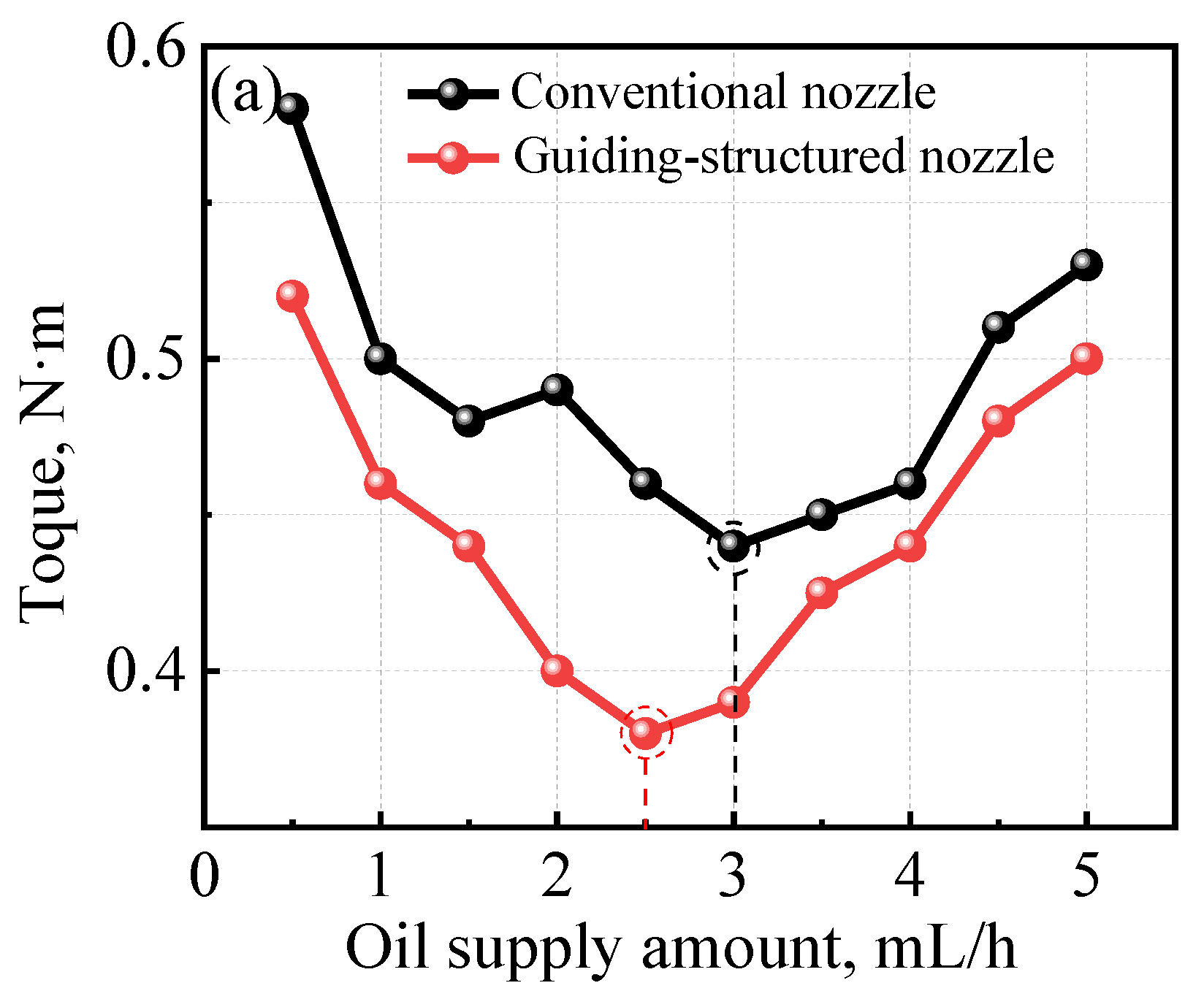
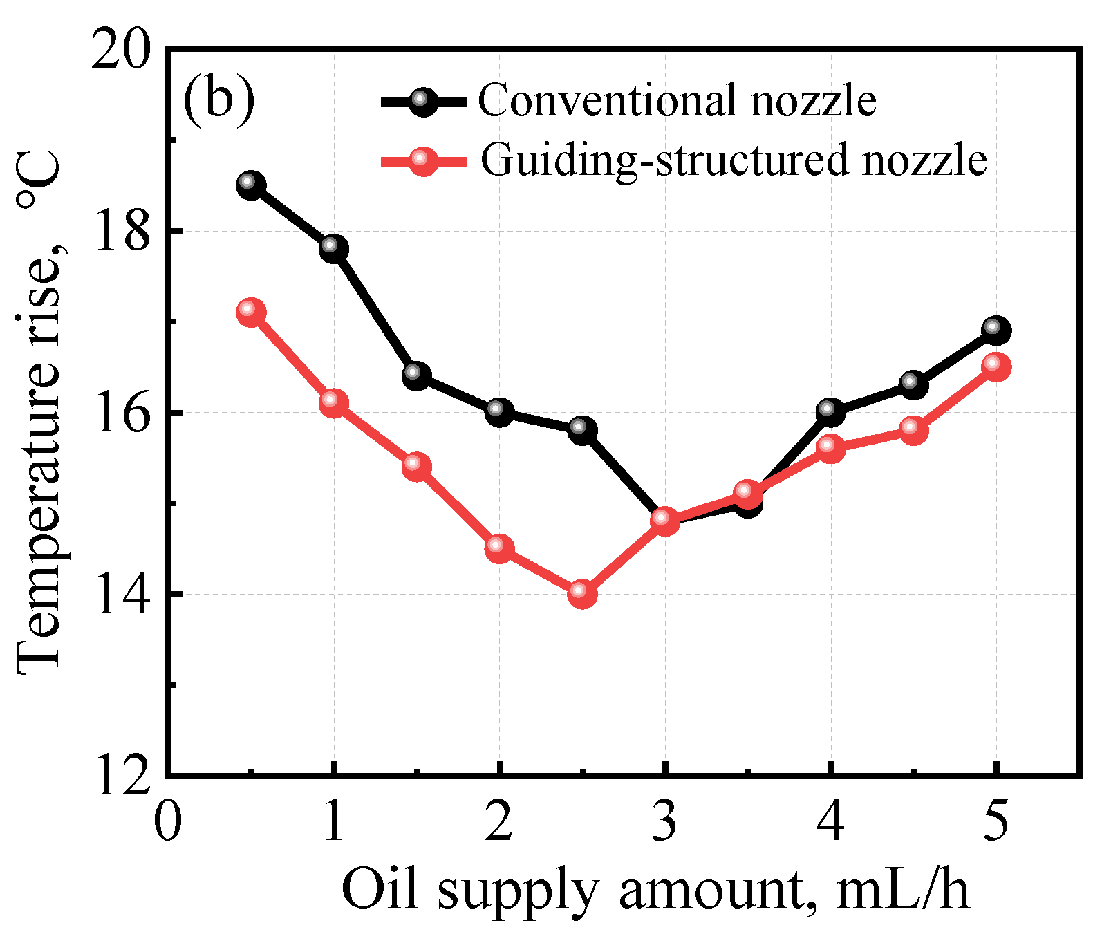
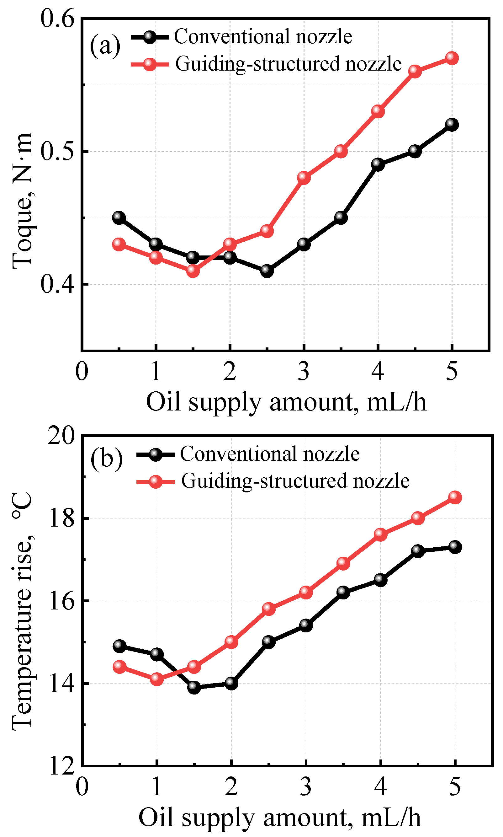
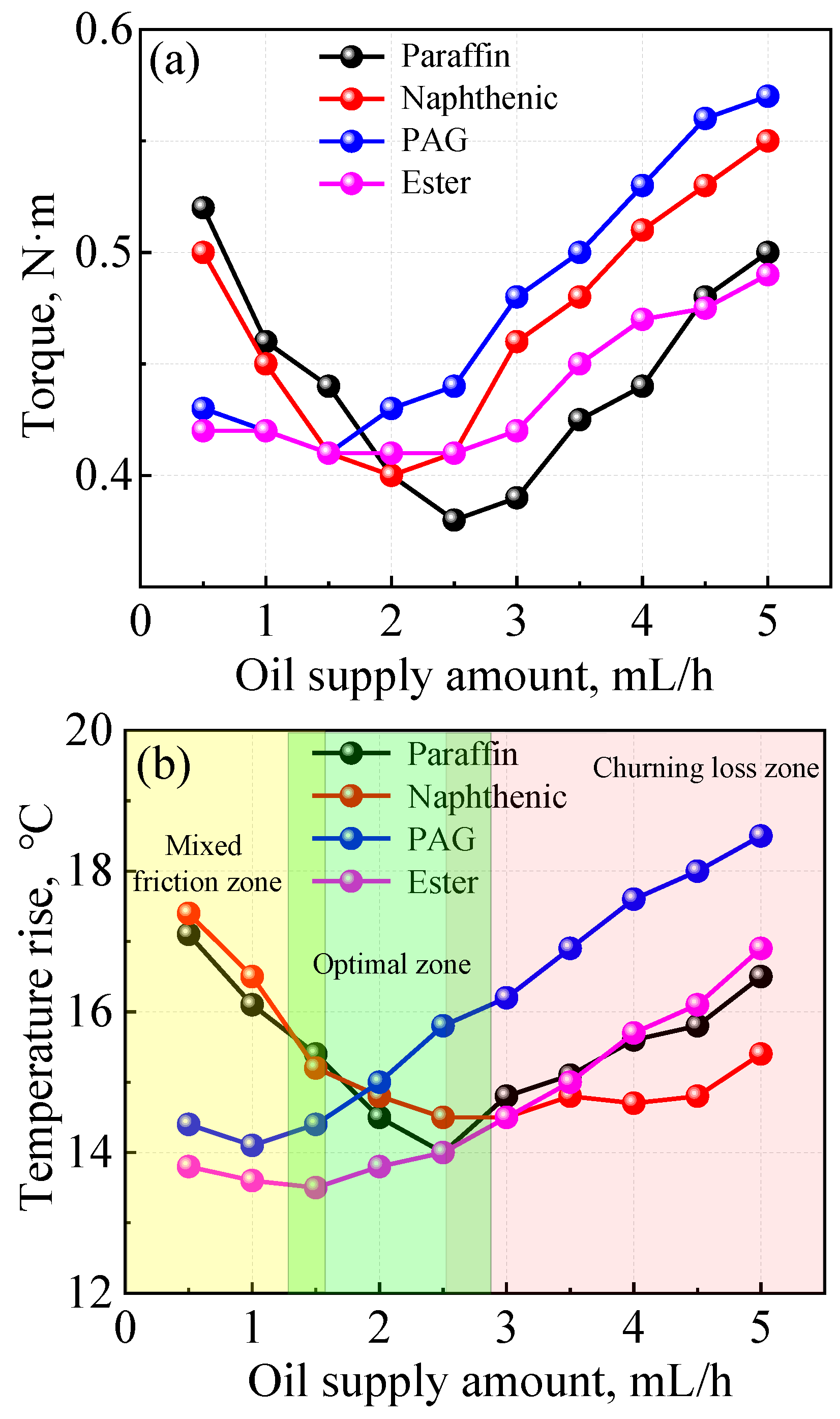
3.1. Nozzle Type and Lubricant Type on the Torque and Temperature Rise

To investigate the impact of nozzle type and lubricant type on bearing performance, experiments were conducted under varying oil supply conditions. Figure 4 illustrates the variations in torque and temperature rise with respect to the oil supply amount when using paraffin-based lubricant. It is important to note that Figure 4 represents the temperature rise, which is defined as the difference between the outer race temperature and the initial temperature prior to testing. The results indicate an initial decrease followed by an increase in both torque and temperature rise. The oil supply amount corresponding to the turning point (minimum value) is considered the optimal oil supply amount. When this amount falls below its optimum value, inadequate oil supply leads to a mixed lubrication regime characterized by surface asperity contacts. As the oil amount increases, these contact surfaces gradually separate due to the formation of lubricating films, resulting in reduced torque and temperature rise. Beyond the optimal value, transitions in the lubrication regime occur from mixed (or starved) lubrication to fully flooded lubrication. The excessive amount of oil leads to reverse flow shear at the inlet, contributing to an increase in temperature. Further increases in oil amount result in churning loss, becoming the primary mechanism for temperature rise. This implies that an over-supply of lubricant does not lead to a higher film thickness but rather causes a reduction in viscosity and weakens film formation.
In Figure 4, the torque measured with the guiding-structured novel is consistently lower than that of the conventional nozzle, particularly when the oil amount is below its optimal value. This observation suggests that the guiding-structured nozzle delivers more amount of oil into the bearing cavity, thereby contributing to film formation. As the oil amount exceeds its optimal value, the torque of the guiding-structured nozzle approaches that of the conventional one. A similar trend can be observed in the corresponding temperature rise curves. Moreover, the superior oil delivery ability of the guiding-structured nozzle also results in a reduced optimal oil supply amount compared to that of the conventional nozzle. That means the utilization of a guiding-structured nozzle results in improved lubrication conditions for bearing operation while simultaneously reducing oil consumption.
The torque and temperature rise of the two types of nozzles using naphthenic oil are compared in Figure 5. One notable distinction when comparing with Figure 4 is that beyond the optimal point; the torque and temperature rise exceed those of conventional nozzles. This can primarily be attributed to the fact that excessive oil delivered by guiding-structured nozzles is more susceptible to churning loss. Additionally, it was observed that the optimal amount for both nozzle types decreased by 0.5 mL/h, indicating a reduction in oil consumption by 15%.
The advantages of the guiding-structured nozzle in oil delivery become more pronounced when using synthetic oil, as depicted in Figure 6 and Figure 7. In Figure 6, it is evident that the optimal oil supply amount for the guiding-structured nozzle is further reduced, resulting in a more prominent churning loss effect and overall curves positioned above those obtained with conventional nozzles. The results depicted in Figure 7 demonstrate that the utilization of a guiding-structured nozzle leads to a reduction in both overall torque and temperature rise, as compared to conventional nozzles.
Besides the nozzle structures, the oil types exert a significant influence on the overall trends of torque and temperature curves. Figure 8 compares the impact of different oil types on bearing performance using guiding-structured nozzles. It is evident that in the mixed lubrication regime, where there is insufficient oil to fully separate the contact surfaces, both synthetic oils exhibit noticeably lower torque and temperature rises compared to mineral oils. This observation highlights the crucial role played by lubricant properties in friction reduction. Synthetic oils are known for their propensity to form an adsorption layer on metal surfaces due to their polar functional groups, which effectively reduces contact frictions and leads to lower bearing torque and temperature rise, as well as a decrease in optimal oil supply amount. As the amount of oil supplied increases, however, the thickness of the lubricating film surpasses that of the adsorption layer. In this case, friction torque and corresponding temperatures are primarily determined by traction resulting from shear within the lubricating film and excessive churning of lubricant outside contacts. Furthermore, the torque and temperature rise resulting from churning are intricately linked to the rheological properties of the oil bulk, including ambient viscosity determined by the viscosity–temperature coefficient and the shear thinning effect. Consequently, these factors, in conjunction with the oil amount, potentially contribute to distinct variations observed in the curves within the churning regime. The lubrication states can be roughly divided into three zones with varying oil supply amounts, as depicted in Figure 8b. In the mixed friction zone, synthetic oils are preferred due to their superior anti-friction properties and lower oil consumption. Within the optimal zone, an acceptable amount of oil is capable of effectively reducing friction between the contact surfaces. However, it is not recommended to operate within the churning loss zone due to both higher friction losses and excessive oil consumption.
As analyzed above, it is anticipated that the bearing will operate within the optimal zone, where both oil consumption and overall friction are minimized. To comprehensively assess the impact of nozzle structures and oil types on bearing performance at this optimum point, Figure 9 quantitatively compares the optimal oil supply quantity and the corresponding torque and temperature rise. From Figure 9a, it can be observed that the guiding-structured nozzle exhibits either lower or equal optimal oil supply amounts, indicating its superior oil delivery capability. By examining the torque in Figure 9b, it is evident that utilizing a guiding-structured nozzle significantly reduces torque due to enhanced oil delivery into the bearing. No distinct advantages of using a guiding-structured nozzle are observed for synthetic oils in Figure 9b, as well as for temperature rise in Figure 9c. This implies that under similar lubrication conditions, employing a guiding-structured nozzle conserves oil consumption. Overall, PAG oil is preferred due to its minimal oil consumption, along with acceptable torque levels and equivalent temperature rise.

3.2. Oil–Air Injection Pattern and Oil Droplet Distributions

The above results indicate that the guiding-structured nozzle exhibits a higher efficacy in delivering oil into the bearing cavity. To further investigate the underlying mechanism of oil delivery, the injection patterns of both conventional and guiding-structured nozzles were examined, as well as the distribution of oil on solid surfaces. A high-speed camera was utilized to capture the jet flow from the nozzles, which sprays onto a glass disc. Simultaneously, a camera installed under the glass disc was employed to observe and record the distribution of oil droplets. Figure 10 illustrates the injection patterns from these two types of nozzles. Here, θ represents the injection angle, which indicates the extent of divergence. It is evident that the injection pattern of the conventional nozzle displays a larger θ, resulting in more oil droplets being sprayed onto both the cage surface and bearing shoulders due to a small gap between the cage and inner ring. In contrast, for the guiding-structured nozzle, the injection angle θ is smaller, resulting in a more concentrated jet flow. This concentration enhances the oil jetting into the bearing and increases its penetration ability to overcome the air curtain.
The distributions of oil droplets on the glass surfaces are illustrated in Figure 11. Overall, the droplets sprayed from the guiding-structured nozzle exhibit a uniform and concentrated distribution on the glass surface, with a finer size. In contrast, the distributions of droplets from the conventional nozzle are irregular, characterized by both small droplets and large aggregates. This discrepancy primarily arises due to the intermittent pumping of oil into the oil–air mixture cell. As the oil flows through the nozzle, it tends to accumulate on its surface, leading to aggregation at the outlet. Once a certain amount of aggregation is reached, an abrupt ejection of oil occurs from the nozzle, resulting in patchy distribution patterns. These discontinuous injections cause fluctuations in oil supply to bearings and consequently affect both film formation stability and bearing temperature regulation within spindle systems. However, the utilization of a guiding-structured nozzle leads to droplet refinement as the oil traverses through the guiding fibers. Furthermore, owing to the high interface energy of nylon fibers, there is low adsorption of oil on its surface, thereby ensuring a continuous jet flow and effective suppression of supply fluctuations.
The diameter range of the droplets of the test lubricants is presented in Table 2. It can be seen that the conventional nozzle exhibits oil droplet diameters ranging from 100 to 600 μm for paraffin and 100 to 400 μm for naphthenic oils, whereas the guiding-structured nozzle reduces these ranges to 40~100 μm and 20~90 μm, respectively. For synthetic oils, the droplet diameter ranges from approximately 30 to 240 μm for PAG oil and 10 to 120 μm for ester oil; however, with the guiding-structured nozzle, these ranges decrease to 10~100 μm and 10~50 μm, respectively. The smaller diameter range achieved by synthetic oils is mainly attributed to their low adsorbability on the nozzle surface, which suppresses oil aggregation. In general, even distribution with smaller droplet size enhances oil delivery efficiency and suppresses the feeding fluctuations, reducing optimal oil supply amount and improving bearing performance by mitigating torque and temperature rise.

4. Conclusions

In order to overcome the blockage of oil delivery into the bearing induced by the air curtain under high-speed conditions, a guiding-structured nozzle is employed to enhance the penetration of jet flow. A series of experiments are conducted on an oil–air lubricated bearing test bench. Meanwhile, two sets of mineral oils and synthetic oils are utilized to validate both the oil delivery capability of the nozzle and its impact on bearing performance. The results demonstrate the advantages offered by the guiding-structured nozzle. Further examination of jet flow patterns and oil distributions on surfaces elucidate the underlying mechanisms governing the oil delivery process and its influence on bearing performance. The main conclusions can be summarized as follows:
(1)
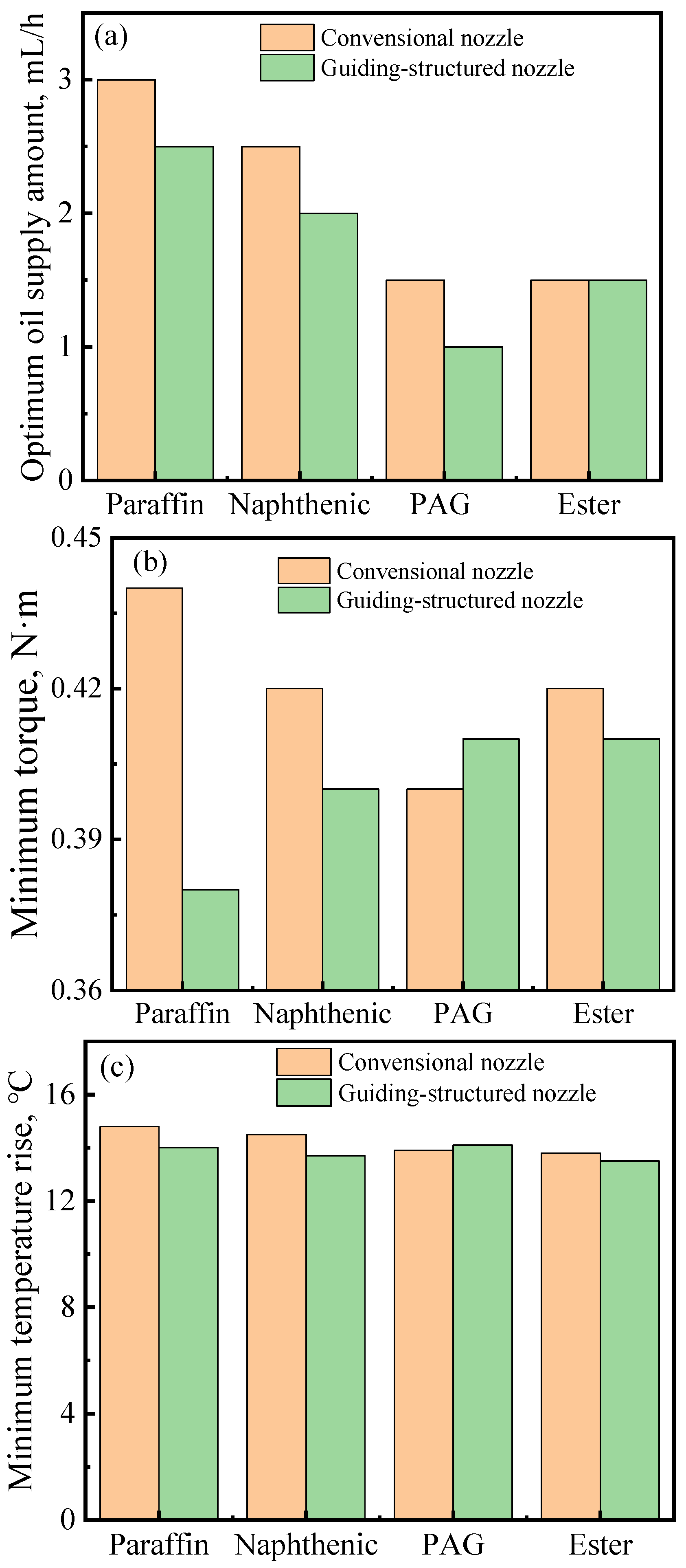
With an increase in the oil supply amount, both torque and temperature initially decrease and then increase, resulting in an optimal oil supply amount at the turning point. All the results indicate that the guiding-structured nozzle exhibits smaller values for the optimal oil supply amount compared to those of the conventional nozzle, highlighting its superior oil delivery capability.
(2)
The synthetic oils exhibit a reduction in the optimal oil supply amount, torque, and temperature rise within the mixed lubrication regime primarily due to their propensity for forming an anti-friction absorption layer on surfaces. Beyond the optimum value, churning loss is predominantly influenced by the properties of bulk oils. Via comprehensive comparisons, it can be concluded that PAG oil demonstrates superior performance.
(3)
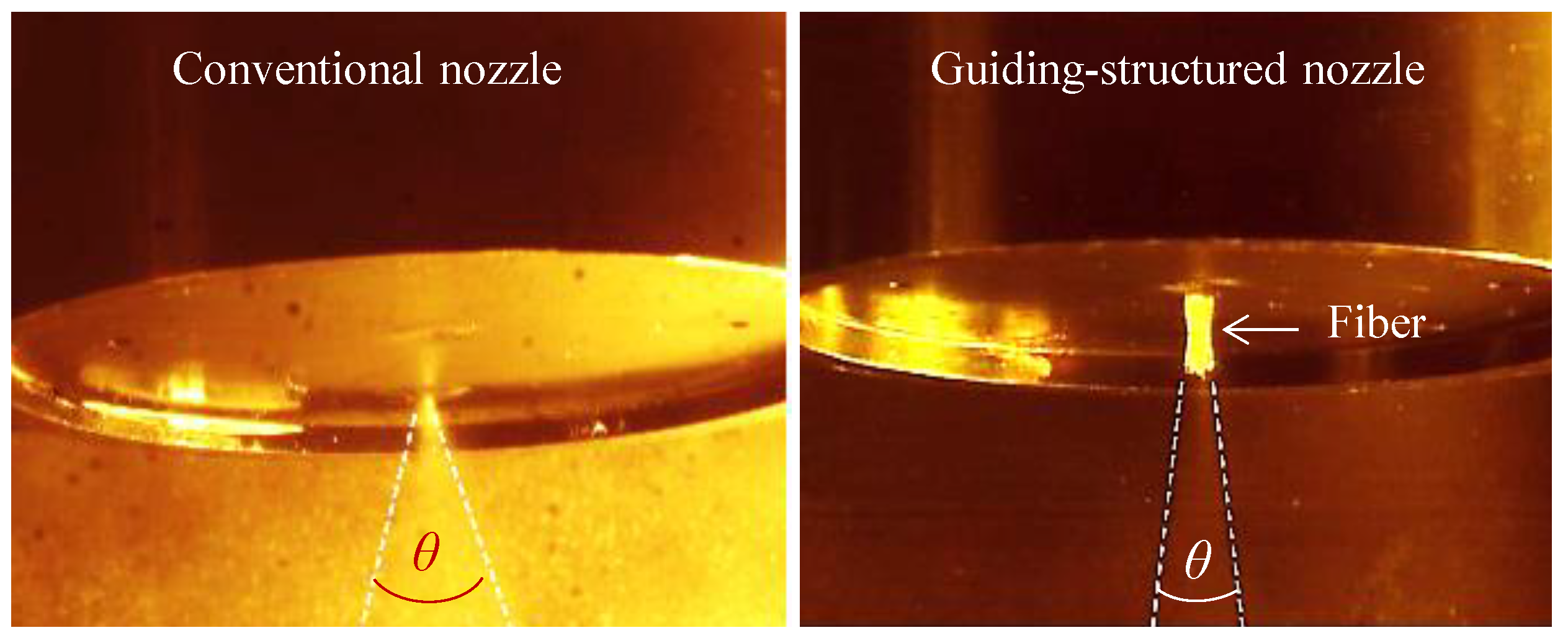
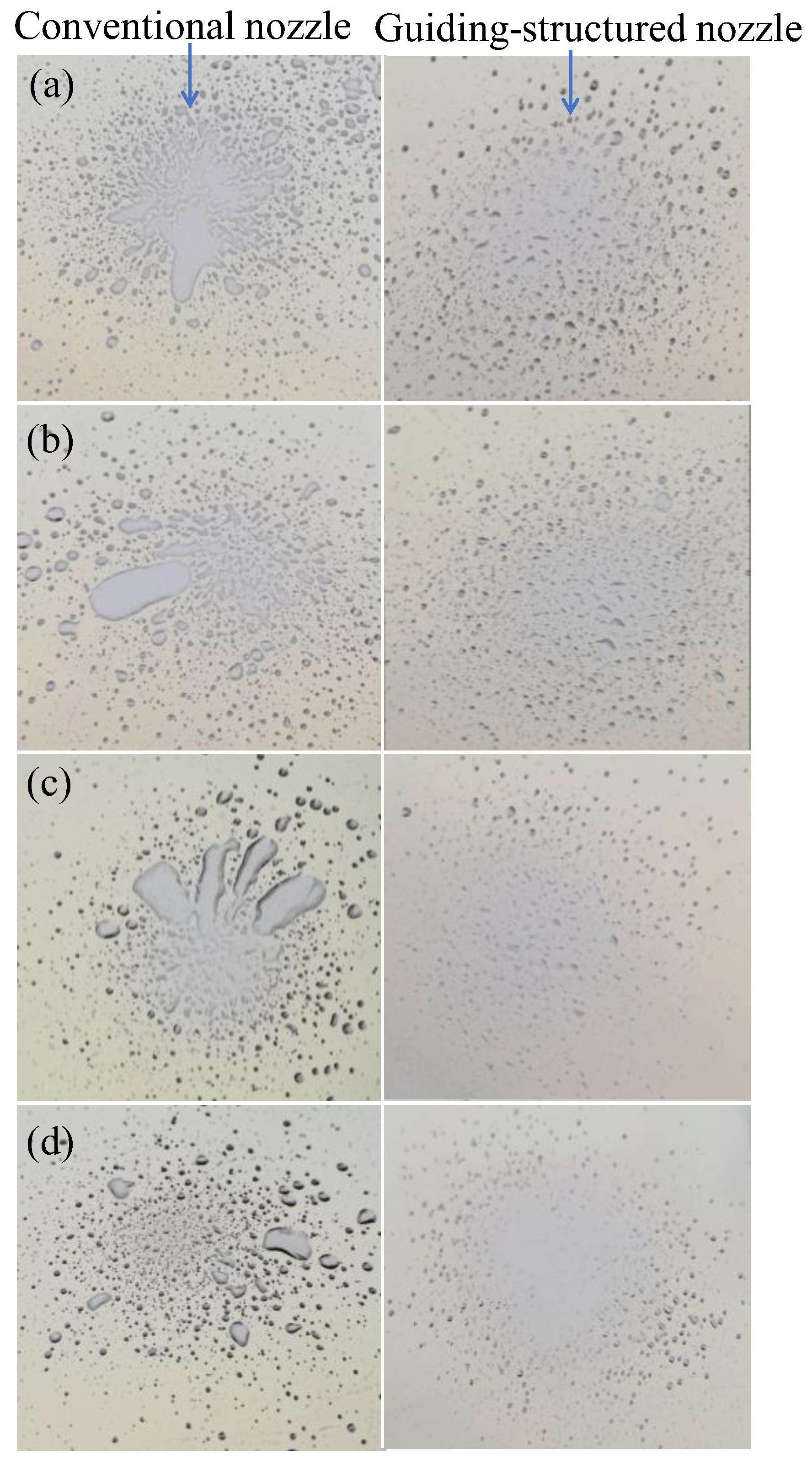
The jet flow patterns of the guiding-structured nozzle exhibit a higher degree of concentration compared to the conventional nozzle, thereby enhancing the penetration capability of the jet flow through the air curtain. Moreover, oil droplets emitted from the guiding-structured nozzle demonstrate uniform distribution with a narrow diameter range. The oil supply stability and the droplet diameter are determined by both the type of nozzle and surface adsorption properties of oils, which subsequently affect oil aggregation at the outlet of the nozzle.
(4)
The results suggest that the regulation of oil delivery and bearing performance can be achieved via nozzle structure design. Further research will be conducted to investigate the influence of parameters such as fiber diameter, fiber number, and fiber material (considering surface wettability) on jet flow patterns and oil droplet size.

Author Contributions

Conceptualization, X.L. and F.G.; Investigation, X.Z., K.C. and X.W.; Methodology, Q.B. and X.J.; Validation, X.L.; Writing—original draft, X.Z. and K.C.; Writing—review and editing, X.L. All authors have read and agreed to the published version of the manuscript.

Funding

This research is funded by the National Natural Science Foundation of China (No. 52275196) and the Youth Innovation and Technology Support Program of Shandong Province (No. 2019KJB010).

Data Availability Statement

The data used to support the findings of this study are included in the manuscript.

Conflicts of Interest

Author Xintian Zi was employed by the company Taian Haina Spindle Science & Technology Co., Ltd. The remaining authors declare that the research was conducted in the absence of any commercial or financial relationships that could be construed as a potential conflict of interest.

References

  1. Jauhari, K. Oil lubrication on high-speed spindle bearing system: A review. Proc. Tribol. Ind. 2014, 16, 216–231. [Google Scholar]
  2. Denkena, B.; Bergmann, B.; Klemme, H. Cooling of motor spindles-a review. Int. J. Adv. Manuf. Tech. 2020, 110, 3273–3294. [Google Scholar] [CrossRef]
  3. Lugt, P. A Review on Grease Lubrication in Rolling Bearings. Tribol. Trans. 2009, 52, 470–480. [Google Scholar] [CrossRef]
  4. Yan, K.; Zhang, J.; Hong, J.; Wang, Y.; Zhu, Y. Structural optimization of lubrication device for high speed angular contact ball bearing based on internal fluid flow analysis. Int. J. Heat Mass. Tran. 2016, 95, 540–5506. [Google Scholar] [CrossRef]
  5. Wand, D.; Liu, S.; Li, Y.; Tong, N. Lubrication technology for ultra high speed motorized spindle bearings to avoid air curtain effect. Bearing 2018, 43, 59–64. [Google Scholar]
  6. Aoyama, T.; Inasaki, I.; Tsutsui, S.; Shimizu, T. Development of an oil-air mist lubrication system with a piezoelectric nozzle for machine tool spindles. Int. J. Mach. Tool. Manu. 1989, 32, 259–263. [Google Scholar]
  7. Jiang, S.; Mao, H. Investigation of the high speed rolling bearing temperature rise with oil-air lubrication. J. Tribol. 2011, 133, 021101. [Google Scholar] [CrossRef]
  8. Kong, X.D.; Yao, J.; Yu, B.; Ai, C.; Song, Y. Summary of oil–air lubrication system development. Lubr. Eng. 2012, 37, 91–95. [Google Scholar]
  9. Ramesh, K.; Yeo, S.H.; Zhong, Z.W. Development of oil air mist lubrication system in ultra high grinding spindle. Int. J. Mach. Tool. Manu. 2002, 42, 95–100. [Google Scholar]
  10. Jeng, Y.R.; Gao, C.C. Investigation of the ball bearing temperature rise under an oil-air lubrication system. Proc. Inst. Mech. Eng. Part J J. Eng. Tribol. 2001, 215, 139–148. [Google Scholar] [CrossRef]
  11. Schmidt, H.; Schwartz, J. Energy-efficient minimal quantity lubrication for high-speed spindles. SKF-Evol. 2014, 9. [Google Scholar]
  12. Dudorov, E.A.; Ruzanov, A.; Zhirkin, Y. Introducing an oil-air lubrication system at a continuous-casting machine. Steel Transl. 2009, 39, 351–354. [Google Scholar] [CrossRef]
  13. Höhn, B.; Michaelis, K.; Otto, H. Minimised gear lubrication by a minimum oil/air flow rate. Wear 2009, 266, 461–467. [Google Scholar] [CrossRef]
  14. Shimomura, T. Development of high-speed angular contact ball bearings for machine tool spindles “High Ability Bearings”. KOYO Eng. J. Engl. Ed. 2002, 161E, 38–45. [Google Scholar]
  15. Kosugi, F.; Kouji, N. Air Oil Lubrication Bearings with Re-lubricating Hole on the Outer Ring for Machine Tool. NTN Tech. Rev. 2010, 78, 45–49. [Google Scholar]
  16. Gao, W.J.; Nelias, D.; Li, K.; Liu, Z.X.; Lyu, Y.G. A multiphase computational study of oil distribution inside roller bearings with under-race lubrication. Tribol. Int. 2019, 140, 105862. [Google Scholar] [CrossRef]
  17. Bao, H.; Hou, X.; Lu, F. Analysis of oil-air two-phase flow characteristics inside a ball bearing with under-race lubrication. Processes 2020, 8, 1223. [Google Scholar] [CrossRef]
  18. Yan, B.; Dong, L.; Yan, K.; Chen, F.; Zhu, Y.S.; Wang, D.F. Effects of oil-air lubrication methods on the internal fluid flow and heat dissipation of high-speed ball bearings. Mech. Syst. Signal. Process. 2021, 151, 10740. [Google Scholar] [CrossRef]
  19. Akatmasu, Y.; Mori, M. Minimizing lubricant supply in an air-oil lubrication system. NTN Tech. Rev. 2004, 72, 12–19. [Google Scholar]
  20. Yan, K.; Wang, Y.; Zhu, Y.; Hong, J.; Zhai, Q. Investigation on heat dissipation characteristic of ball bearing cage and inside cavity at ultra high rotation speed. Tribol. Int. 2016, 93, 470–481. [Google Scholar] [CrossRef]
  21. Nakamura, S. Technology development and future challenge of machine tool spindle. J. SME Jpn. 2012, 42, 445–448. [Google Scholar]
  22. Zeng, Q.; Zhao, X.; Dong, G.; Wu, H. Study on lubrication properties of Nitinol 60 alloy used as high-speed rolling bearing and numerical simulation of flow pattern of oil-air lubrication. Trans. Nonferrous Met. Soc. China 2012, 22, 2431–2438. [Google Scholar] [CrossRef]
  23. Zeng, Q.; Zhang, J.; Hong, J.; Liu, C. A comparative study on simulation and experiment of oil-air lubrication unit for high speed bearing. Ind. Lubr. Tribol. 2016, 68, 325–335. [Google Scholar] [CrossRef]
  24. Cheng, L.; Jinhua, Z.; Ke, Y.; Zhai, Q.; Zeng, Q. Influence of nozzle structure on the two-phase flow characteristic in oil-air lubrication system for high-speed rolling bearing. Lubr. Eng. 2015, 40, 28–31. [Google Scholar]
  25. Min, W.B.; Chen, B.; Yang, N.; Yan, W. Influences of nozzle structure on air curtain effect in oil-air lubrication of angular contact ball bearings. Chin. Mech. Eng. 2021, 32, 2197–2202. [Google Scholar]
  26. Wu, W.; Hu, J.B.; Yuan, S.; Hu, C. Numerical and experimental investigation of the stratified air-oil flow inside ball bearings. Int. J. Heat Mass Transf. 2016, 103, 619–626. [Google Scholar] [CrossRef]
  27. Yan, K.; Wang, Y.T.; Zhu, Y.S.; Hong, J. Investigation on the effect of sealing condition on the internal flow pattern of high-speed ball bearing. Tribol. Int. 2017, 105, 85–93. [Google Scholar] [CrossRef]
  28. Chen, C.; Li, J.; Yu, Y.; Xue, Y. Study on the effect of nozzle parameters on annular flow in oil-air lubrication. Manuf. Technol. Mach. Tool 2019, 2, 64–69. [Google Scholar] [CrossRef]
  29. Wang, Y.; Song, G.; Niu, W.; Zhang, Y. Influence of oil nozzle structure parameters on oil injection direction. Ind. Lubr. Tribol. 2021, 73, 1–7. [Google Scholar] [CrossRef]
  30. Hu, J.; Xun, B.; Zhang, X.-M.; Zhang, Q.-Y.; Li, G.-W. Design and research of new-type nozzle structure based on oil–air lubrication. Meccanica 2024, 59, 1–18. [Google Scholar] [CrossRef]
Figure 1. Assembly of test bench and side section view of the test head.
Lubricants 12 00060 g001
Figure 2. Nozzle types and structures. (a) Conventional nozzle, (b) guiding-structured nozzle, (c) photo of guiding-structured nozzle, (d) drawing of nozzle.
Lubricants 12 00060 g002
Figure 3. Variations in torque and temperature with time, (a) torque, (b) temperature, Fr = 2.0 kN, Fa = 1.0 kN, S = 3.0 mL/h, PAO10.
Lubricants 12 00060 g003aLubricants 12 00060 g003b
Figure 4. Variations in torque and temperature rise with oil supply amount, (a) torque, (b) temperature, Fr = 2.0 kN, Fa = 1.0 kN, 9000 rpm, paraffin.
Lubricants 12 00060 g004aLubricants 12 00060 g004b
Figure 5. Variations in torque and temperature rise with oil supply amount, (a) torque, (b) temperature, Fr = 2.0 kN, Fa = 1.0 kN, 9000 rpm, naphthenic.
Lubricants 12 00060 g005aLubricants 12 00060 g005b
Figure 6. Variations in torque and temperature rise with oil supply amount, (a) torque, (b) temperature, Fr = 2.0 kN, Fa = 1.0 kN, 9000 rpm, PAG.
Lubricants 12 00060 g006
Figure 7. Variations in torque and temperature rise with oil supply amount, (a) torque, (b) temperature, Fr = 2.0 kN, Fa = 1.0 kN, 9000 rpm, ester.
Lubricants 12 00060 g007
Figure 8. Comparisons of oil types on torque and temperature rise, (a) torque, (b) temperature, guiding-structured nozzle.
Lubricants 12 00060 g008
Figure 9. Comparisons of nozzle structures and oil types on optimal oil supply amount and bearing performance. (a) Optimal oil supply amount, (b) minimum torque, (c) temperature rise.
Lubricants 12 00060 g009
Figure 10. Comparisons of injection pattern of two types of nozzles.
Lubricants 12 00060 g010
Figure 11. Comparisons of oil droplet distributions with two types of nozzles and oil samples. (a) Paraffin, (b) naphthenic, (c) PAG, (d) ester.
Lubricants 12 00060 g011
Table 1. Properties of test lubricants.
LubricantsDensity
(kg/m3 at 22 °C)
Dynamic
Viscosity
(Pa·s at 22 °C)
Kinematic
Viscosity
(mm2·s at 40 °C)
Viscosity
Index
MineralParaffin8630.07946103
Naphthenic9490.1344650
SyntheticPAG10890.11646210
Ester9700.10846120
Table 2. The diameter range of oil droplet on glass plate under different oil samples.
LubricantsConventional Nozzle
(μm)
Guiding-Structured Nozzle
(μm)
MineralParaffin100~60040~100
Naphthenic100~40020~90
SyntheticPAG30~24010~100
Ester10~12010~50
Disclaimer/Publisher’s Note: The statements, opinions and data contained in all publications are solely those of the individual author(s) and contributor(s) and not of MDPI and/or the editor(s). MDPI and/or the editor(s) disclaim responsibility for any injury to people or property resulting from any ideas, methods, instructions or products referred to in the content.

