Article

Effect of Grease Viscosity on Channeling Properties of Ball Bearings

1
Advanced Technology R&D Center, NTN Corporation, 5-105, Hidamarinooka, Kuwana 511-0867, Japan
2
CAE R&D Center, NTN Corporation, 1578, Higashikaizuka, Iwata 438-0851, Japan
3
Department of Electrical and Mechanical Engineering, Nagoya Institute of Technology, Gokisochou, Nagoya 466-8555, Japan
*
Author to whom correspondence should be addressed.
Lubricants 2024, 12(1), 13; https://doi.org/10.3390/lubricants12010013
Submission received: 15 November 2023 / Revised: 20 December 2023 / Accepted: 3 January 2024 / Published: 4 January 2024
(This article belongs to the Special Issue Friction and Wear of Rolling-Element Bearings)

Abstract

:
Grease-lubricated rolling bearings transition from the churning phase to the channeling phase. This transition property affects grease life and torque properties. Therefore, the relationship between grease yield stress and grease degradation during operation, which affects this transition, has been investigated. However, there have been few studies on grease flow that affects the transition. In this study, the mechanism of grease reduction on the races was investigated for small bearings operated at low speeds, where thermal degradation and softening of the grease are less likely to occur. It was inferred that the grease transfer to the cage affects the channeling transition and that the amount of transfer varies depending on the initial grease viscosity. These findings can be applied to grease composition and cage design and are useful in providing bearings with excellent low-torque characteristics, such as in industrial motor applications.

1. Introduction

To achieve carbon neutrality, rolling bearings are increasingly shifting from oil lubrication to grease lubrication [1]. Grease has complex rheological properties [2,3]. The frictional torque of bearings with grease lubrication is different from that of bearings with oil lubrication [4]. With grease lubrication, the torque varies greatly depending on the lubrication state, which can be either in the churning phase or the channeling phase [5,6]. In the churning phase, the grease is stirred due to the rotational movement of the bearing induced by the rolling elements and the cage. This stirring leads to an increase in frictional torque. In the channeling phase, most of the grease in the bearing is not in the area traversed by the rolling elements and cage [7,8]. As a result, there is less stirring of the grease, and the torque is low [9]. In the initial stages of operation, bearings filled with grease are typically in the churning phase. Over time, the grease is gradually displaced from the area traversed by the rolling elements and cage. Eventually, the lubrication state transitions from the churning phase to the channeling phase [10]. In the channeling phase, the amount of lubricant near the contact point of the bearing is stable if the effects of grease degradation, such as evaporation and thickener fiber degradation, are not considered [11]. However, the amount of lubrication changes before the transition to the channeling phase. Therefore, this transition can affect the efficiency of machinery and equipment. It is thus desirable to use grease that can quickly transition to the channeling phase after the start of the bearing operation. Oil bleeding characteristics can be improved by reducing the grease channeling transition time in the bearing [12].
The channeling transition has been studied in relation to the rheological properties of greases, and it is widely known that the yield stress of the grease affects the transition [13]. In general, grease undergoes softening and thermal degradation during the churning process. The churning phase is assumed to end when the shear force of the grease at the bearing becomes less than the yield stress of the grease. Cann [14] showed that shear disrupts the network structure of the thickener during operation and softens the grease. The rate of degradation and change in the microstructure of these greases depends on the energy input to the grease. Thus, Chatra et al. used atomic force microscopy (AFM) to measure the yield stress of grease before and after stirring and correlated it with changes in microstructure [15,16] and found that the loading energy density and heat transfer entropy density affect the thermal and mechanical degradation of grease [17]. Methods have also been proposed to evaluate the degree of grease degradation. Acar et al. [18] and Zhou et al. [19] estimated yield stress as a function of energy using the Arrhenius equation and provided grease degradation parameters. Osara et al. [20] also applied fundamental thermodynamics to grease to derive its characteristic material properties, including yield stress, and the channeling transition process due to grease degradation is becoming clearer. On the other hand, for bearings operated at small and/or low rotational speeds, changes in grease properties due to shear and thermal degradation caused by stirring are expected to be small. Therefore, it can be inferred that the channeling transition is highly dependent on the grease flow due to the initial grease characteristics and the bearing geometry. Cen et al. [21] applied the theory of oil lubrication [22] and showed that the torque characteristics during operation change depending on the base oil viscosity, rotational speed, and the size of the contact point between the balls and raceway ring. It has also been shown that the initial grease-filling amount [16] affects the channeling transition. However, there are still many unknowns regarding the detailed flow of grease in the bearing leading to the channeling transition and its relationship to grease viscosity, which must affect the flow.
The purpose of this study is to clarify the relationship between grease flow and grease viscosity characteristics that affect the channeling transition for small bearings operated at low speeds. Bearings operated under such conditions are less affected by changes in grease properties due to grease degradation and grease flow due to centrifugal force. Therefore, the channeling phase transition was considered to depend on the reduction of grease on the bearing race. To understand the mechanism of this grease reduction, a model of grease reduction near the contact point was constructed based on observations of grease on the bearing race and cage after operation. Grease flow was then simulated, and the effect of grease viscosity properties on the flow was examined. Finally, the grease reduction model was validated by examining the relationship between the channeling phase transition time and grease viscosity properties using 12 grease types with different base oil viscosities and thickener types.

2. Proposed Mechanism of Transition to Channeling Phase in Bearings

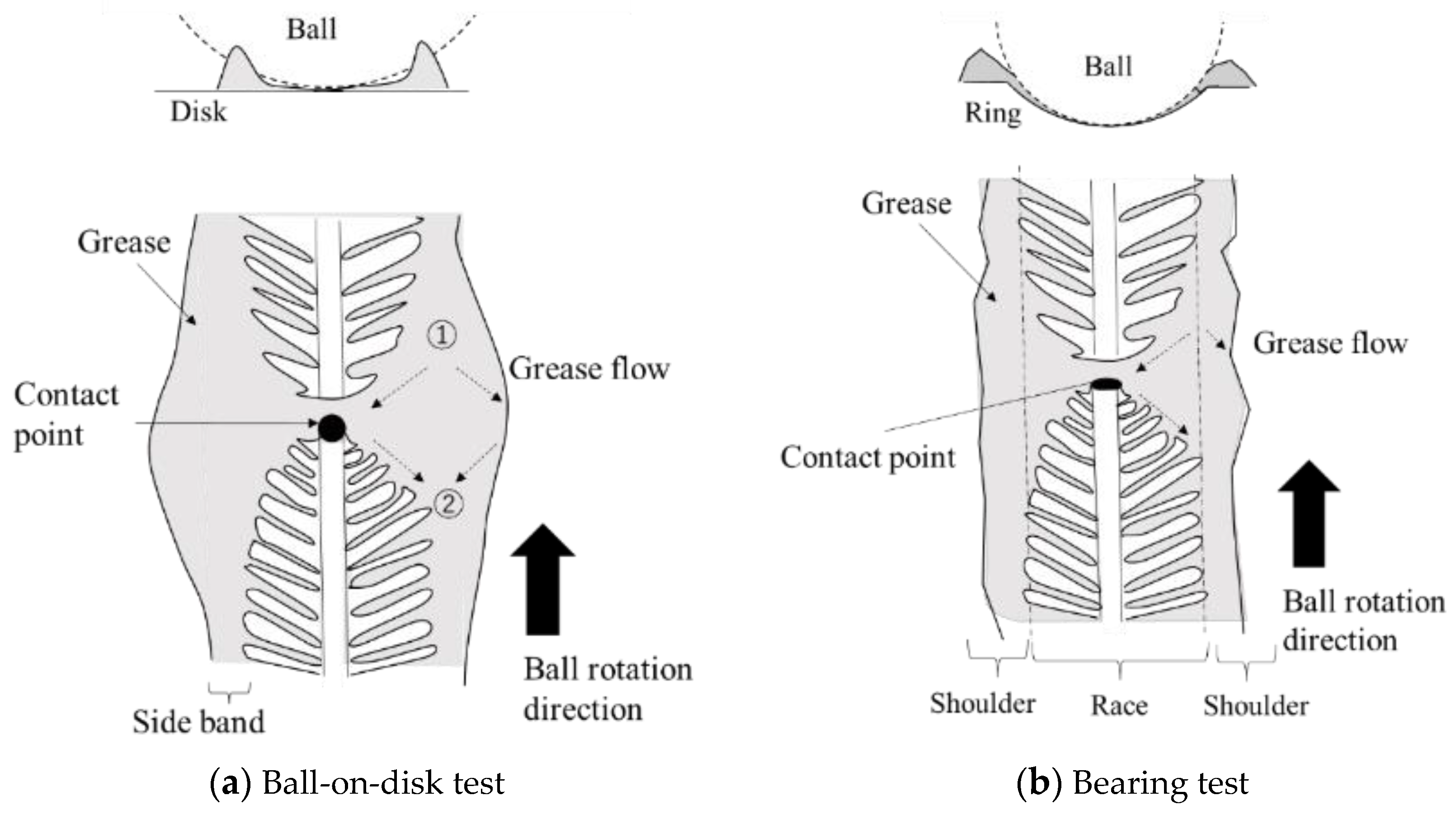
2.1. Observation of Grease Flow in Bearing

For small bearings operating at low speeds, the shear forces acting on the grease are small, so the increase in bearing temperature and grease degradation are almost negligible. Consequently, the effect of the lower yield stress of the grease on the channeling transition is minimal. In addition, the centrifugal force due to bearing rotation is small and does not affect grease flow. Therefore, the lubrication condition of the bearing is determined by the flow of grease in the space through which the balls pass. To identify the factors affecting the channeling transition, grease flow in the bearing was observed.
Figure 1 shows the bearing operating equipment, and Table 1 shows the test conditions. The testing equipment is designed to apply load from the axial direction, and the frictional torque during operation can be detected by a load cell. The thrust ball bearing (NTN 51204) is used for testing and could be easily disassembled for observation. The materials of the test bearing are steel for the rings and balls and glass-fiber reinforced nylon for the cage. The ball diameter is 9/32 inches, and the P.C.D. (pitch circle diameter) of the ball is 30 mm. The sample grease consisted of polyolester base oil and urea thickener. Figure 2 shows the grease distribution in a raceway after testing. Branch-shaped grease residue remained in the race. Grease accumulated on the ring shoulder along the direction of the ball rolling. The latter grease arrangement was not observed in element tests, such as the ball-on-disk test [23]. It is thus assumed that the grease flow depends on the geometry of the bearing. The bearing cage also affects the grease flow. Therefore, the influence of these factors on grease reduction in the race was investigated.

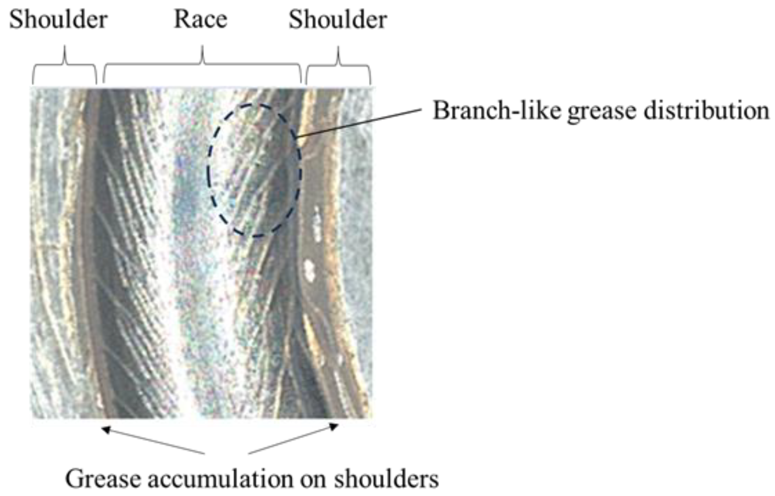
2.2. Effect of Bearing Shoulders on Grease Flow

Figure 3a shows a diagram of the observed grease flow near the contact point in the ball-on-disk test, and Figure 3b shows the estimated grease flow near the contact point based on the remaining grease on the bearing ring shown in Figure 2. In the ball-on-disk test, the grease near the contact point takes a butterfly shape. In front of the contact point, the grease moves in two directions, namely toward and away from the center of the track, as shown by the arrows labeled “①” in the Figure, because the clearance between the ball and the disk becomes smaller toward the contact point. Behind the contact point, the grease moves in the direction of the arrows labeled “②” in the Figure, forming a side band because the clearance becomes larger as the ball rotates. However, in the bearing test, the grease near the contact point does not take a butterfly shape. Because there is a large space between the ball and the shoulder, grease that flows onto the shoulder in front of the contact point accumulates on it. In other words, this grease is not resupplied within the race except by oil separation. The ring shoulder affects grease reduction near the contact point in the early stages of bearing operation (i.e., when the race contains a large amount of grease).

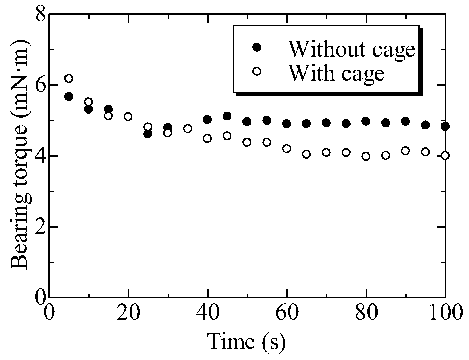
2.3. Effect of Cage on Grease Flow

Element tests such as the ball-on-disk test use no cage. A paper [24] has noted the influence of the cage on grease flow during bearing operation, but the effect of the cage on the reduction of grease in the race is unclear. To study the effect of the cage on grease flow, torque measurements were performed for bearings with and without a cage. The test conditions were the same as those in Table 1. For bearings without a cage, torque increases due to ball-to-ball contact. However, under these conditions, the torque increase due to this effect is less than 3% of the total torque and can thus be ignored. Figure 4 shows the torque measurement results. There was no difference in torque values measured with and without a cage in the initial 30 s of operation. Thus, it was inferred that the reduction of grease near the contact point in the early stages of operation depends on grease flow to the shoulder. In contrast, after 30 s, the torque measured with a cage is smaller than that measured without a cage.
Figure 5 shows the grease on the cage and balls after the test. As shown, grease accumulated on the cage. This indicates that the grease on the balls was scraped off and adhered at the pocket edges of the cage. This flow contributes to the reduction of grease near the contact point. Therefore, when examining the channeling properties of various types of grease in bearings, it is necessary to consider grease flow due to the cage.

2.4. Mechanism of Grease Reduction on Lubricated Surfaces

In previous sections, the reduction of grease near the contact point was shown to be influenced by the shoulder and cage of the bearing. The flow of grease to the shoulder strongly depends on the geometry of the balls and races. The amount of grease scraped off by the cage is inferred to depend on the clearance in the cage pocket and the shape of the grease residue on the balls. Therefore, we investigated the effect of the shape of the grease residue on the balls on the amount of grease scraped off.
Figure 6 shows the generation of branch-like grease residue behind the contact point. The A, B, C, and D in the Figure show the position behind the contact point. Behind the contact point, the grease elongates mainly in the direction normal to the race due to the increase in the clearance between the ball and the race. Then, as shown in A, a neck develops in the grease. As the grease moves to B, the neck becomes thinner due to a further increase in the clearance. Finally, the grease breaks, as shown in C. The grease adhered to the ball then reaches the cage as the ball rotates. At this point, the grease on the ball with a thickness greater than the clearance of the cage pocket is removed by the edge of the cage pocket, as shown in D.
The steady-state flow behavior of grease exhibits complex strain-response behavior to stress [25]. In the range of yield stress, grease viscosity decreases rapidly with increasing shear rate stress, and in the high shear rate range, viscosity asymptotically approaches a value like that of oil. These changes are influenced by changes in the grease thickener network [26], so the flow differs from grease to grease even at the same shear rate. In addition, Abdulrazaq et al. [27] have analyzed viscoelastic fluids, such as grease, during elongational deformation and found that the yield stress threshold, surface tension coefficient, and viscosity ratio in the material during elongation affect the elongation characteristics. Here, the grease reduction due to the cage is considered when the deformation of the fluid with yield stress is conical and parabolic, as in the results of Nelson et al. [28]. Figure 7 shows the grease shape during elongation. For simplicity, the model is for grease elongation between parallel disks. In the parabolic case (Case B), the angle of the bottom surface with respect to the direction of elongation is large and decreases as it approaches the broken surface. This shape varies depending on the test conditions and the viscosity characteristics of the grease. The outline shape of the grease when it breaks is assumed to be an ellipse. The angle of the bottom grease surface with respect to the direction of elongation is 90°, and the angle of the break surface is 0°.
Consider grease reduction due to grease removal by the cage in the conical shape case. With the initial grease volume denoted as V0 and the bottom area denoted as A, the grease height on one side at the first break, h1, can be expressed as
h 1 = 3 V 0 2 A
Next, assume that the grease with a thickness greater than the pocket clearance c on one side of the break is removed by the cage. The bottom area of the cone to be removed, Ac, can be expressed as
A c = ( h 1 c ) 2 A h 1 2
The amount of grease reduction by the cage at the first break, ΔV1, can be expressed as
Δ V 1 = ( h 1 c ) 3 A 3 h 1 2
Next, consider the amount of grease reduction after the second break. In a bearing, the grease on the ball and race collects in front of the contact point. It then moves behind the contact point and elongates again. Therefore, the grease height at the second break, h2, can be expressed by Equation (6) based on the relationship between Equations (4) and (5). Here, the area of the bottom surface A is assumed to be constant (i.e., unchanged from the first break).
V 0 Δ V 1 2 = A h 2 3
h 2 = 3 2 A ( V 0 Δ V 1 )
h 2 = h 1 ( h 1 c ) 3 2 h 1 2
Considering that the grease beyond the pocket clearance c is removed, as in the first break, the second reduction of grease, ΔV2, can be expressed as
Δ V 2 = ( h 2 c ) 3 A 3 h 2 2
Therefore, the amount of grease present on the balls and races after n breaks, Vn, is expressed as
V n = V 0 - k = 1 n ( h n c ) 3 A 3 h n 2
Now, consider grease reduction due to grease removal by the cage in the parabolic shape case. The outline of the grease, when it breaks, is a function of the following ellipse:
f 1 ( y ) = ( 1 1 ( y h 1 ) 2 h 1 2 ) A π
where the y-axis is the direction of elongation. From Equation (9), the initial grease volume V0 can be expressed as
V 0 2 = 0 h 1 π f 1 ( y ) 2 d y
Under the assumption that grease thicker than the pocket clearance c is eliminated, the first reduction of grease, ΔV1, can be expressed as
Δ V 1 = c h 1 π f 1 ( y ) 2 d y
Therefore, the amount of grease on the ball and race after n breaks, Vn, is expressed as
V n = V 0 k = 1 n c h n π f n ( y ) 2 d y
Figure 8 shows the relative volume of grease remaining versus the number of elongations obtained from Equations (8) and (12). The initial volume V0 is based on a conical shape at 45° to the direction of elongation, and the pocket clearance c is half the radius of the bottom area. In both cases, the grease volume decreased as a power law function of the number of elongations. The conical shape has a smaller decrease in volume than the parabolic shape. Therefore, it is qualitatively shown that the channeling transition for rolling bearings depends on the shape of the grease residue behind the contact point. In bearings, the cage pocket clearance may change depending on the operating conditions. However, it is inferred that the relationship between the relative channeling properties of each grease due to differences in flow during elongation is not affected.

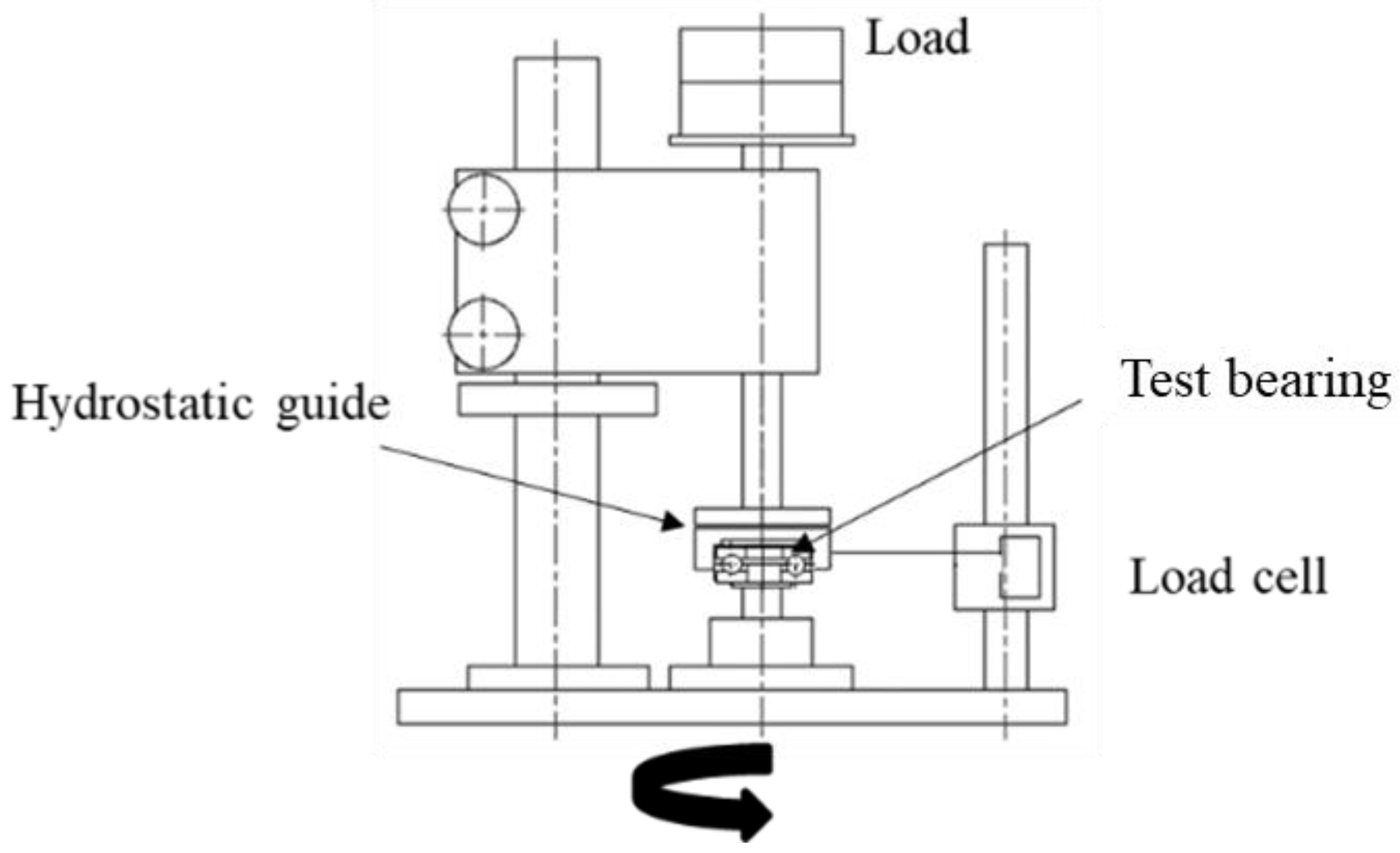
3. Material and Method

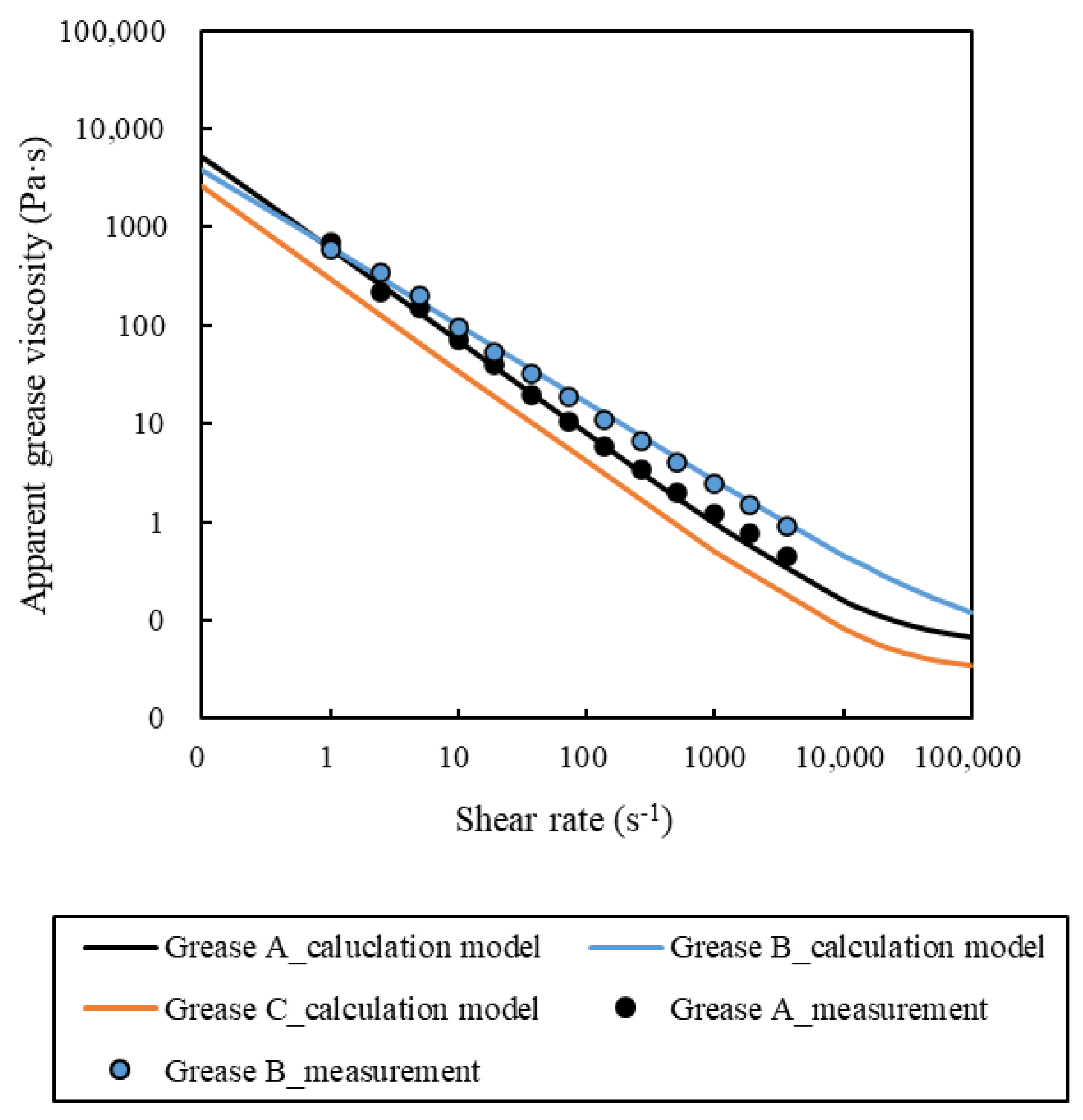
3.1. Grease Properties for Flow during Elongation

The viscosity of grease depends on shear rate and temperature [29]. Since the subject of this study is small bearings operated at low speeds, heat generation is low, and the effect of temperature on grease viscosity is considered negligible. Therefore, grease viscosity is used as a representative property to simulate the elongational flow by numerical fluid analysis.

3.1.1. Grease Model

The Cross Power law [30] expressed in Equation (13) is applied to the grease viscosity property model:
η = η γ = + η γ = 0 η γ = 1 + ( m γ ) n
where η is the apparent viscosity of the grease, ηγ=∞ is the viscosity at infinite shear rate, ηγ=0 is the viscosity at zero shear rate, m is the time at which the linear behavior changes to a power law, and n is the flow index.
The coefficients of the Cross–Power law for the model used in the analysis are shown in Table 2. Figure 9 shows the relationship between the shear rate and the apparent viscosity for each type of grease. The coefficients for Grease A and Grease B were obtained by measuring the viscosity of the grease using a rotational viscometer (HAAKE MARS, Thermo Scientific). They differ in viscosity at each shear rate and in the flow index (i.e., the rate of change of viscosity with respect to shear rate). Grease C was set as the coefficient whose viscosity is half that of grease A at each shear rate to investigate the effect of absolute viscosity.

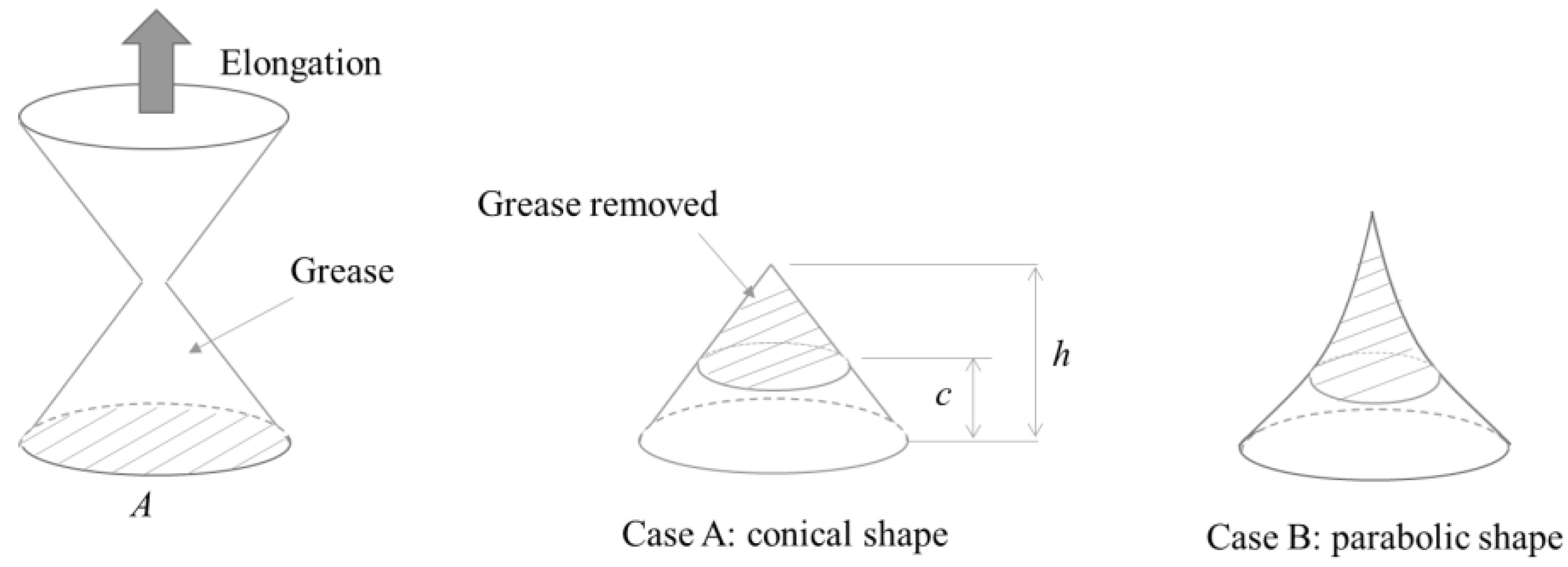
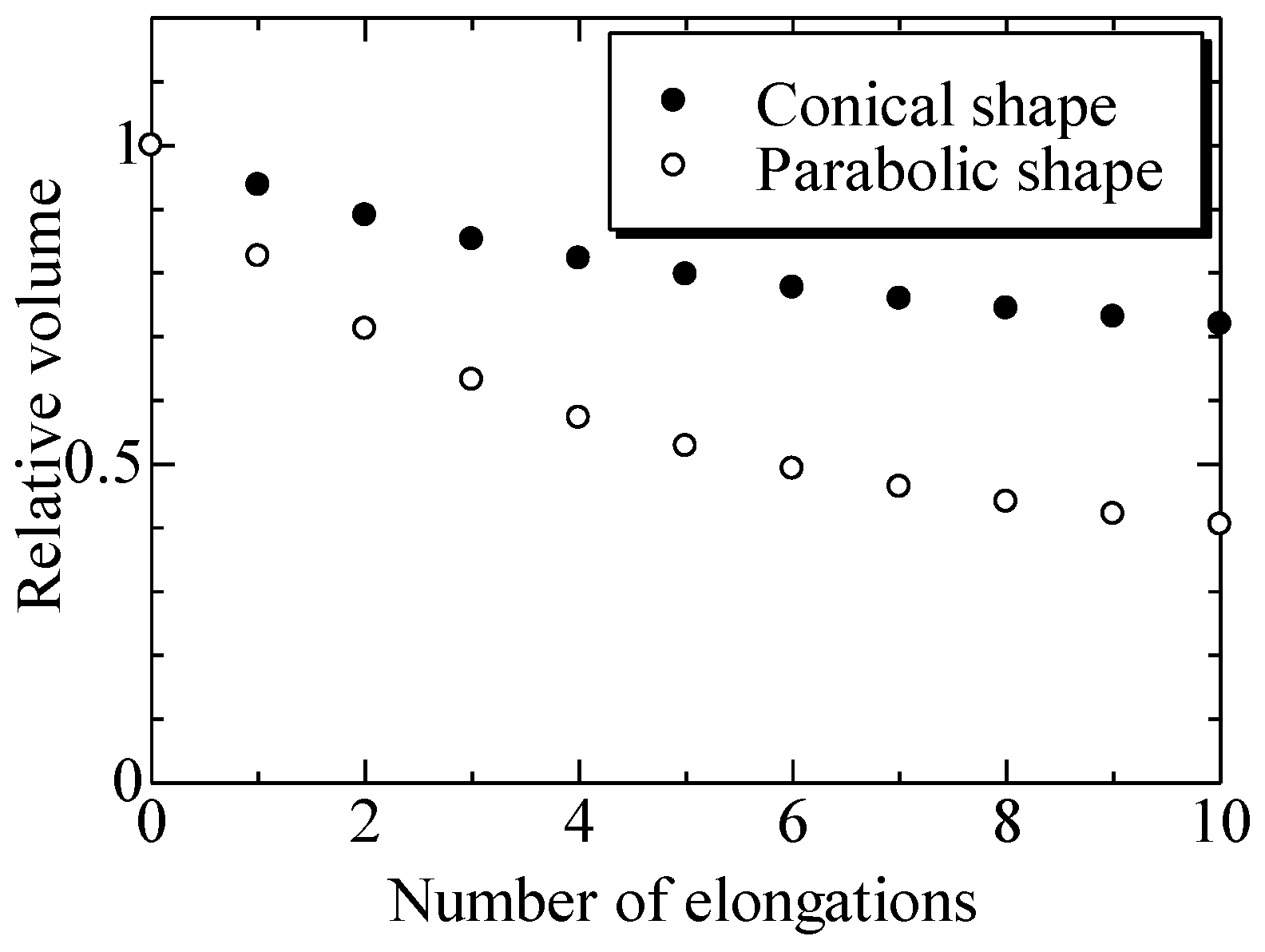
3.1.2. Grease Elongation Model

OpenFOAM v11 [31], an open-source computational fluid dynamics software, was used for the analysis. The two-phase interDyMFoam solver developed for dynamic mesh processing is based on the interFoam solver for static meshes. The governing equations are the following equation of continuity and the Navier–Stokes equation.
u i x i = 0
( ρ u i ) t + x j ( ρ u j u i ) = p x i + x j μ ( u j x i + u i x j ) + f i
where t is time, f is the external force term, ρ is density, and μ is the viscosity coefficient.
The solver tracks the interface between two fluids using the Volume of Fluid (VOF) method [32]. The VOF method is an excellent tool for simulating complex free surface deformation, including dam break. The solver that deforms the mesh as the rigid body moves is implemented.
Figure 10 shows the grease elongation analysis model. The analysis is performed with the top surface fixed and the bottom surface moving until the grease breakage. The computational domain is the hatched area 0.5 mm from the bottom surface, which is 5° in the circumferential direction relative to the initial grease configuration. To reduce calculation time, the circumferential cross section is defined to be axisymmetric in the circumferential direction, and the upper surface is plane-symmetric in the upper direction of the Figure. Hexa mesh is used for the mesh, and the mesh elements are 30 × 500. The number of meshes is not changed in the calculation, but a moving mesh is applied in which the mesh size increases in the vertical direction as the analysis domain moves. The elongation speed is set to 5 mm·s−1. Additional analysis is performed at an elongation speed of 10 mm·s−1 for Grease A to investigate the effect of velocity on grease flow. The grease shape and the shear rate for the grease at each point of the mesh are calculated.

3.2. Channeling Properties of Bearings

3.2.1. Sample Grease

The composition of the greases used in the tests is shown in Table 3. Four types of base oil and thickener are used. The flow index is determined from the shear viscosity properties at 25 °C and obtained using a rotational viscometer (HAAKE MARS, Thermo Fisher Scientific, New York, NY, USA).

3.2.2. Operating Conditions for Bearings

To evaluate the channeling properties of each grease, the torque during bearing operation is measured. Table 4 shows the test conditions. The groove ball bearing (NTN 6204) was used for testing. The materials of the test bearing were steel for the rings and balls and glass-fiber-reinforced nylon for the cage. The ball diameter was 5/16 inch, and the P.C.D. (pitch circle diameter) of the ball was 34.5 mm. The axial load was 20 N, and the inner ring rotational speed was 1200 min−1. Grease was sealed on the races of the inner and outer rings. The amount of grease was about 10% of the total space volume for the bearing corresponding to that space. Figure 11 shows an example of torque during bearing operation. The rolling resistance depends on the amount of lubricant at the contact point between the ball and the race. When the amount of lubricant at the inlet of the contact point decreases, the oil film decreases, and the rolling resistance, which affects torque, decreases rapidly. The channeling phase is defined as the bearing operating condition after this phenomenon occurred. The operating time until this phenomenon occurred is evaluated as the channeling phase transition time.

4. Result and Discussion

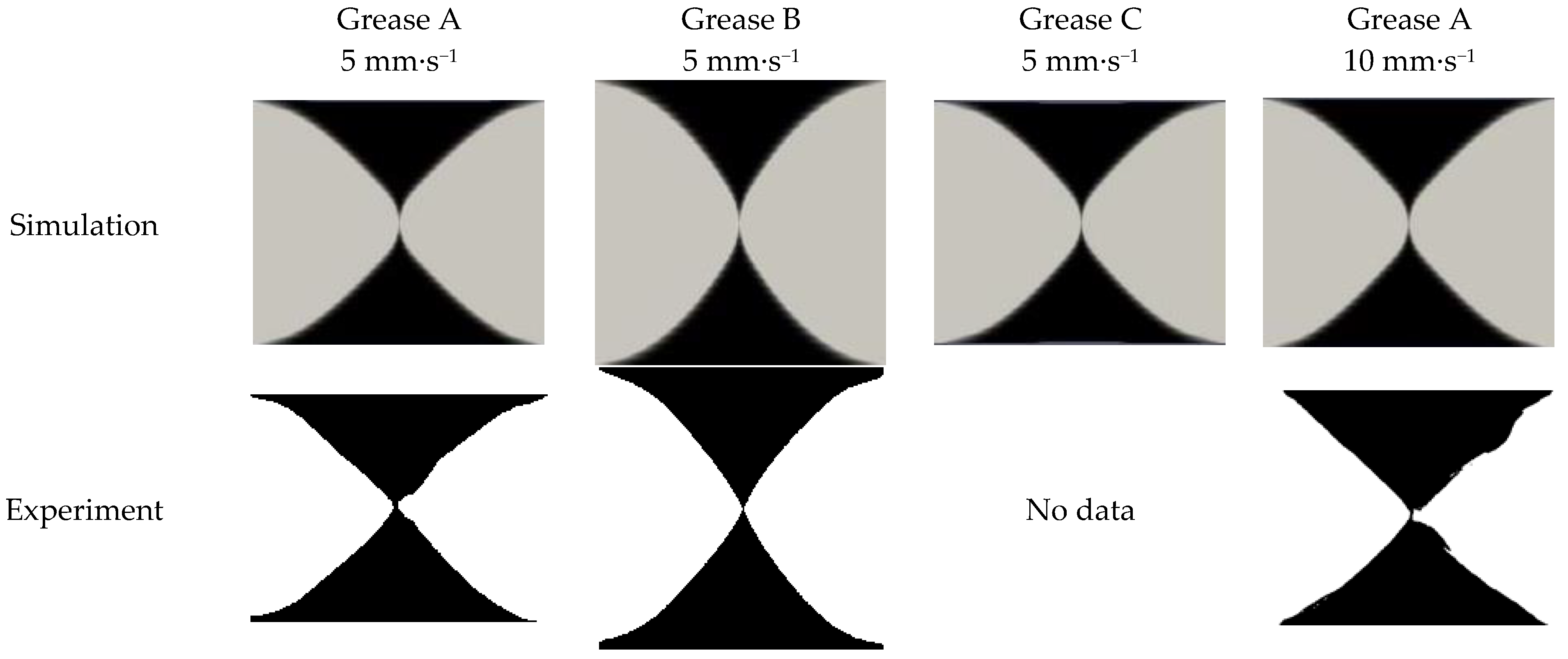
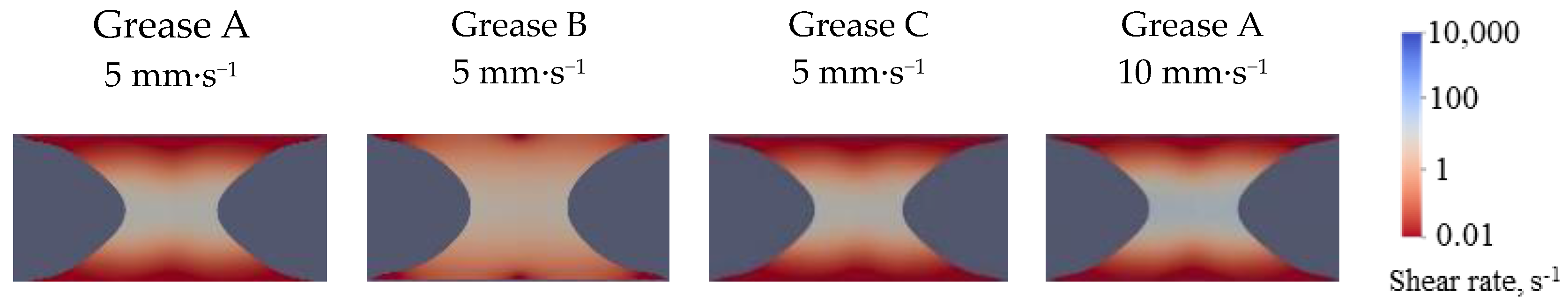
4.1. Grease Flow Analysis during Elongation

Figure 12 shows the simulation and experimental results for the grease shape when the grease breaks during elongation. To confirm the validity of the grease flow in the analysis, experiments were conducted with Grease A and Grease B using the same system as that in the simulation. The grease shapes obtained in the analysis and the experiment are in good agreement. Therefore, the grease flow during elongation could be reproduced by the viscosity model based on the Cross–Power law. Next, consider the effect of apparent viscosity on grease flow. The shapes of Grease A and Grease C are almost the same, including differences in the elongation speed. The grease viscosity properties, except for the flow index, have little influence on the flow. Grease B has a different flow index than Grease A and Grease C and, thus, has a different shape.
This difference is evident from the shear rate distribution during elongation, shown in Figure 13. For an elongation speed of 5 mm·s−1, Grease B flowed more than Grease A and Grease C. The shear rate near the wall was large only for Grease B, for which the entire grease flowed, including that near the wall. Since there is a relationship between shear rate and grease viscosity, as shown in Figure 9, the shear rate distribution in Figure 13 represents the viscosity distribution. For Grease B, which has a small flow index value, the viscosity ratio near the wall surface and at the maximum neck was small, whereas for Grease A and Grease C, which have large flow index values, the viscosity ratio was large. The viscosity ratio caused differences in grease flow. For the same grease, the viscosity ratio does not change even if the elongation speed and the viscosity change. Therefore, the effect of elongation speed on grease shape was almost negligible.
Figure 14 shows the simulated grease shape when the grease breaks at the flow index values from 0.7 to 1.0. The values of the coefficients other than the flow index are the same as for Grease A. The higher the value of the flow index, the smaller the elongation rate. The breakage shape became conical when the elongation ratio was small and parabolic when the elongation ratio was small. Thus, the smaller the flow index, the more grease is removed by the cage, which is inferred to promote the channeling transition in the bearing.

4.2. Evaluation of Channeling Properties of Bearings

Figure 15 shows the relationship between the channeling phase transition time and the flow index. The temperature increase for the bearing during the test was less than 1 °C, and grease degradation was considered to have an effect. A strong correlation (R2 = 0.931) was obtained between the channeling phase transition time and the flow index. The smaller the value of the flow index, the shorter the channeling phase transition time. This is consistent with the discussion presented in Section 4.1. Therefore, the rate of change of grease viscosity with respect to grease shear rate is important for grease channeling properties in bearings operated at low speeds. In addition, Table 3 shows that for the same base oil viscosity, the flow index is smaller for greases with higher thickener content. This suggests that the higher the thickener content, the smaller the viscosity reduction effect on shear rate change and the shorter the channeling phase transition time.

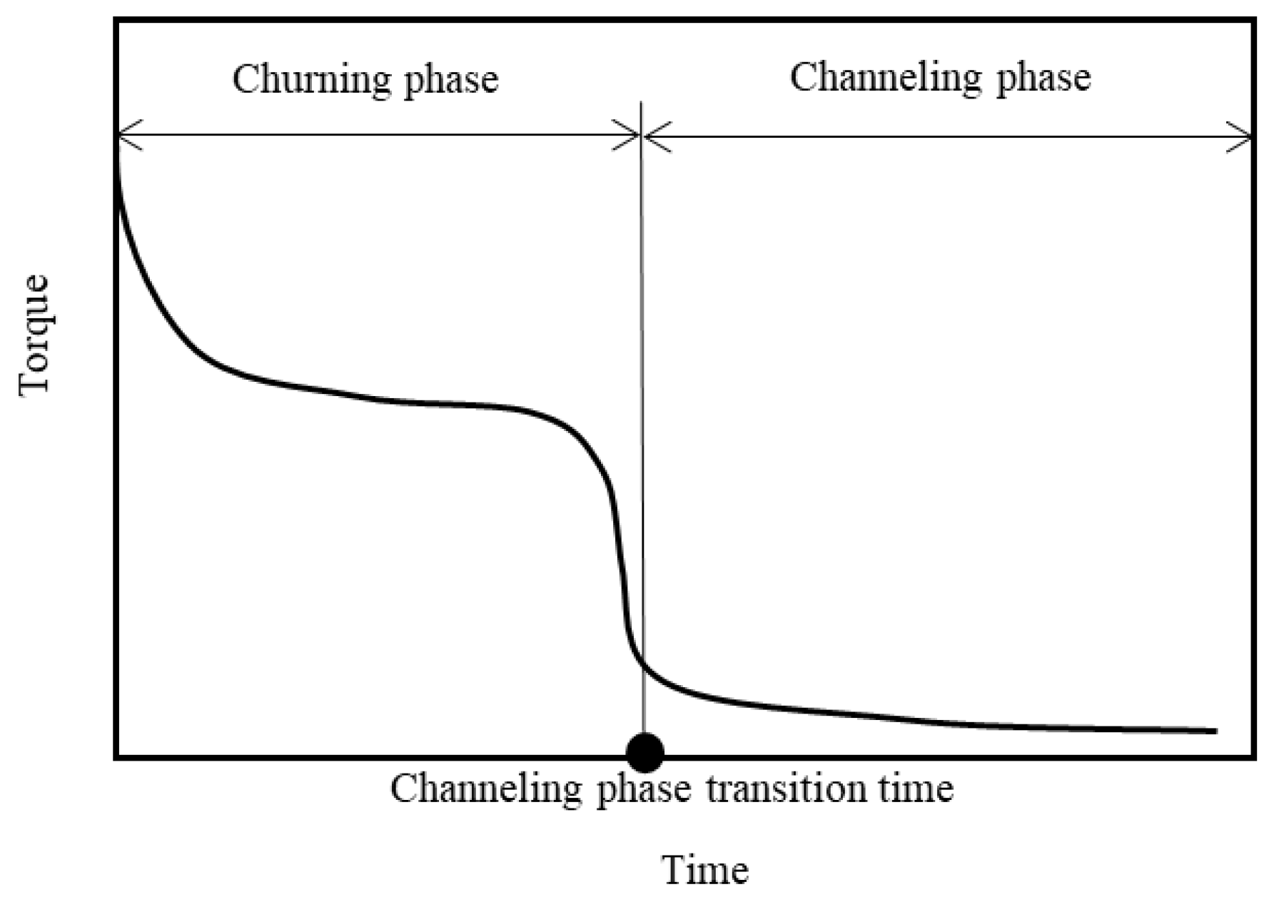
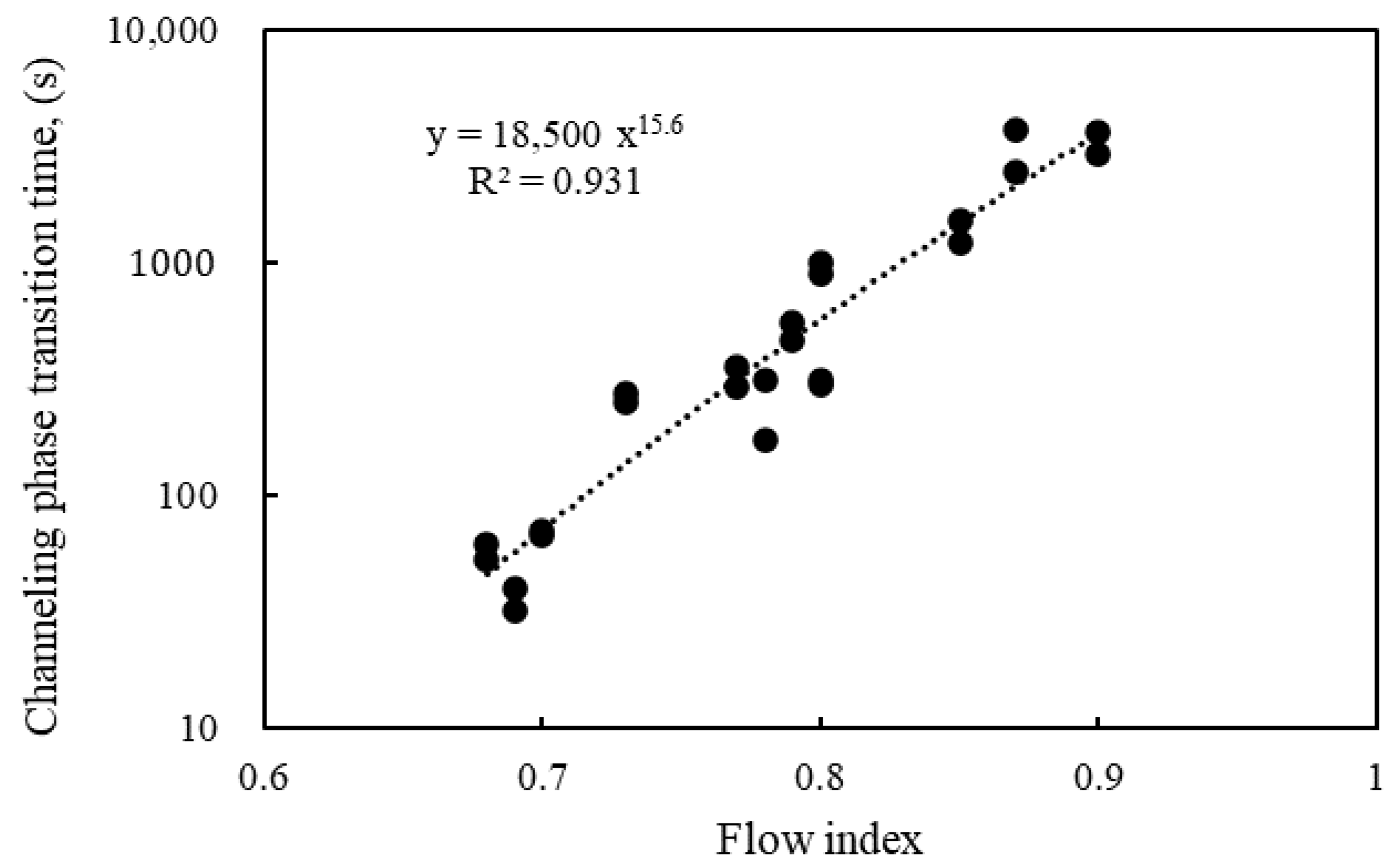
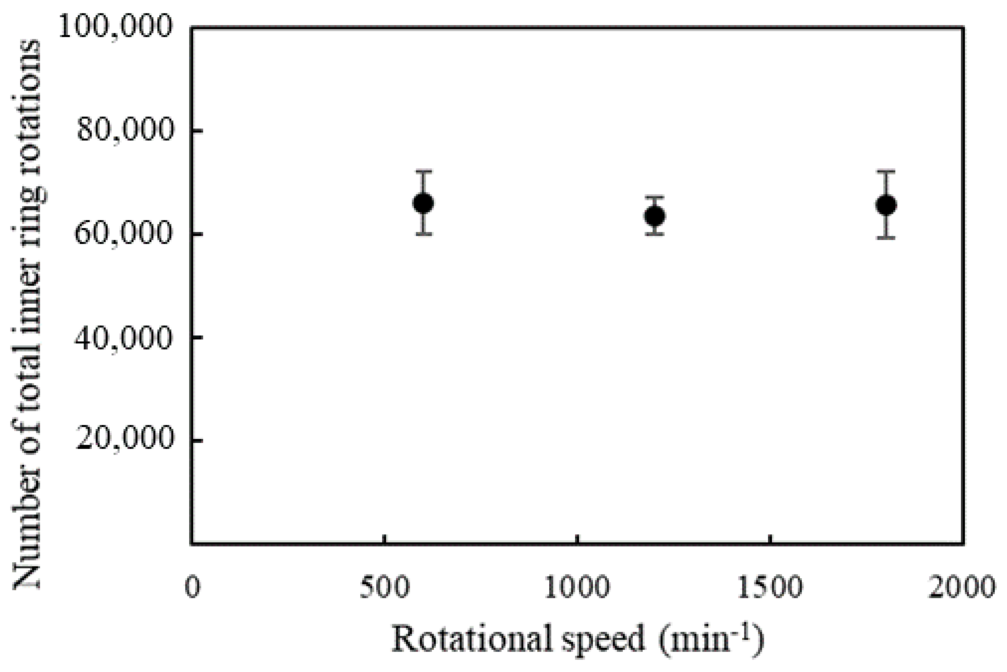
4.3. Relationship between Channeling Phase Transition Time and Rotational Speed

The effect of the bearing rotation speed on the channeling phase transition time is investigated. The test conditions are shown in Table 5. The rotational speeds are 600, 1200, and 1500 min−1, and the sample grease is A1 (Table 3).
Figure 16 shows the channeling phase transition time for each rotational speed. The channeling phase transition time decreased with increasing rotational speed. From the simulation results in Section 4.1, the rotational speed is expected to have little effect on the flow of grease during elongation behind the contact point. Thus, it is assumed that the channeling properties depend on the number of times the grease on the ball surface is scraped off by the cage.
Figure 17 shows the relationship between the total number of inner ring rotations up to the channeling phase transition and rotational speed. The total number of rotations was constant regardless of the rotational speed. The results indicate that the grease flow behind the contact point is independent of rotational speed and that the channeling phase transition time is determined by the number of times the cage removes grease from the ball.

5. Conclusions

In this study, the mechanism of grease reduction on the races was investigated for small bearings operated at low speeds, where thermal degradation and softening of the grease are less likely to occur. Per the results, the following findings were obtained:
Observation of grease distribution in the bearing after operation showed that grease accumulation on the bearing shoulder and grease scraping off the ball surface by the cage affect the transition from the churning phase to the channeling phase of the grease lubrication state in the bearing. Torque measurements with and without cages indicate that the transition to the channeling phase was strongly influenced by the reduction of grease on the race by the cage.
Numerical fluid analysis was conducted based on the assumption that the grease removed by the cage is influenced by the grease flow behind the contact point between the ball and the race. The results showed that the elongation flow was dependent on the rate of change of viscosity with respect to the shear rate of the grease. The channeling phase transition time in bearings was evaluated and found to be highly correlated with the rate of change of grease viscosity with respect to shear rate. This indicates that the grease flow behind the contact point changes the amount of grease removed by the cage and affects the channeling phase transition time in the bearing. It was also inferred that the higher the thickener content of the grease, the lower the rate of change of viscosity with respect to the shear rate and the shorter the channeling transition.
In summary, these findings can be applied to grease composition and cage design and are useful in providing bearings with excellent low-torque characteristics, such as in industrial motor applications.

Author Contributions

Conceptualization, T.O. and H.F.; methodology, T.O., H.F., F.I. and S.M.; validation, T.O. and H.F.; formal analysis, T.O.; investigation, T.O.; resources, T.O. and H.F.; data curation, T.O.; writing—original draft preparation, T.O.; writing—review and editing, T.O., H.F., F.I. and S.M.; visualization, T.O.; supervision, F.I. All authors have read and agreed to the published version of the manuscript.

Funding

This research received no external funding.

Data Availability Statement

The data presented in this study are available on request from the corresponding author.

Conflicts of Interest

Author Hiroki Fujiwara was employed by the company NTN. The remaining authors declare that the research was conducted in the absence of any commercial or financial relationships that could be construed as a potential conflict of interest.

References

  1. Qiang, H.; Anling, L.; Yuan, S.; Lili, L.; Zeqiang, L.; Benliu, P. Design and application on experimental platform for high-speed bearing with grease lubrication. Adv. Mech. Eng. 2015, 7, 1687814015618640. [Google Scholar] [CrossRef]
  2. Akutsu, T.; Masuko, M.; Suzuki, A. Structural Change of Lubricating Grease Considered from Viscous Reduction by Shear. J. Jpn. Soc. Tribol. 2007, 52, 445–452. (In Japanese) [Google Scholar]
  3. Cousseau, T.; Graça, B.M.; Campos, A.V.; Seabra, J.H. Influence of grease rheology on thrust ball bearings friction torque. Tribol. Int. 2012, 46, 106–113. [Google Scholar] [CrossRef]
  4. Cousseau, T.; Graça, B.; Campos, A.; Seabra, J. Friction torque in grease lubricated thrust ball bearings. Tribol. Int. 2011, 44, 523–531. [Google Scholar] [CrossRef]
  5. Horth, A.C.; Norton, J.H.; Paltenden, W.C. Temperature rise characteristics of greases in rolling element bearings. Lubr. Eng. 1971, 27, 380–385. [Google Scholar]
  6. Lugt, P.M. Grease Lubrication in Rolling Bearings; Wiley: Hoboken, NJ, USA, 2012; ISBN 9781118353912. [Google Scholar]
  7. Sakai, K.; Kostal, D.; Shitara, Y.; Kaneta, M.; Krupka, I.; Hartl, M. Influence of Li Grease Thickener Types on Film Thicknesses Formed between Smooth and Dented Surfaces. Tribol. Online 2017, 12, 262–273. [Google Scholar] [CrossRef]
  8. Noda, T.; Shibasaki, K.; Miyata, S.; Taniguchi, M. X-ray CT Imaging of Grease Behavior in Ball Bering and Numerical Vali-dation of Multi-Phase Flows Simulation. Tribol. Online 2020, 15, 36–44. [Google Scholar] [CrossRef]
  9. Oikawa, E.; Inami, N.; Hokao, M.; Yokouchi, A.; Sugimura, J. Bearing torque characteristics of lithium soap greases with some synthetic base oils. Proc. Inst. Mech. Eng. Part J J. Eng. Tribol. 2012, 226, 575–583. [Google Scholar] [CrossRef]
  10. Hoshino, M. Flow properties of lubricating greases and Torque in Rolling Bearings. J. Jpn. Soc. Lubr. Eng. 1980, 25, 547–561. (In Japanese) [Google Scholar]
  11. Lugt, P.M. A Review on Grease Lubrication in Rolling Bearings. Tribol. Trans. 2009, 52, 470–480. [Google Scholar] [CrossRef]
  12. Chatra, K.S.; Osara, J.A.; Lugt, P.M. Impact of grease churning on grease leakage, oil bleeding and grease rheology. Tribol. Int. 2022, 176, 107926. [Google Scholar] [CrossRef]
  13. Miyanaga, N.; Nihei, M.; Tomioka, J. Effects of Flow Properties of Lithium Soap Greases on Bearing Torque. Key Eng. Mater. 2019, 823, 123–127. [Google Scholar] [CrossRef]
  14. Cann, P. Grease degradation in a bearing simulation device. Tribol. Int. 2006, 39, 1698–1706. [Google Scholar] [CrossRef]
  15. Chatra, K.R.; Lugt, P.M. Channeling behavior of lubricating greases in rolling bearings: Identification and characterization. Tribol. Int. 2019, 143, 106061. [Google Scholar] [CrossRef]
  16. Chatra, K.R.; Lugt, P.M. The process of churning in a grease lubricated rolling bearing: Channeling and clearing. Tribol. Int. 2021, 153, 106661. [Google Scholar] [CrossRef]
  17. Chatra, K.R.; Osara, J.A.; Lugt, P.M. Thermo-mechanical aging during churning in grease lubricated bearings and its impact on grease life. Tribol. Int. 2023, 181, 108248. [Google Scholar] [CrossRef]
  18. Acar, N.; Franco, J.M.; Kuhn, E. On the shear-induced structural degradation of lubricating greases and associated activation energy: An experimental rheological study. Tribol. Int. 2019, 144, 106105. [Google Scholar] [CrossRef]
  19. Zhou, Y.; Lugt, P.M. On the application of the mechanical aging Master Curve for lubricating greases to rolling bearings. Tribol. Int. 2020, 141, 105918. [Google Scholar] [CrossRef]
  20. Osara, J.A.; Chatra, S.; Lugt, P.M. Grease material properties from first principles thermodynamics. Lubr. Sci. 2023, 36, 36–50. [Google Scholar] [CrossRef]
  21. Cen, H.; Lugt, P.M. Replenishment of the EHL conatacts in a grease lubricated ball bearing. Tribol. Int. 2020, 146, 106064. [Google Scholar] [CrossRef]
  22. Cann, P.; Damiens, B.; Lubrecht, A. The transition between fully flooded and starved regimes in EHL. Tribol. Int. 2004, 37, 859–864. [Google Scholar] [CrossRef]
  23. Åström, H.; Östensen, J.O.; Höglund, E. Lubricating Grease Replenishment in an Elastohydrodynamic Point Contact. J. Tribol. 1993, 115, 501–506. [Google Scholar] [CrossRef]
  24. Obata, T.; Itoigawa, F. Quantitative Observation of Grease Behavior for Rolling Bearings Using Splitting Phenomena of Colorant. J. Jpn. Soc. Tribol. 2022, 67, 54–60. (In Japanese) [Google Scholar]
  25. Delgado, M.A.; Secouard, S.; Valencia, C.; Franco, J.M. On the Steady-State Flow and Yielding Behaviour of Lubricating Greases. Fluids 2019, 4, 6. [Google Scholar] [CrossRef]
  26. Hodapp, A.; Conrad, A.; Hochstein, B.; Jacob, K.-H.; Willenbacher, N. Effect of Base Oil and Thickener on Texture and Flow of Lubricating Greases: Insights from Bulk Rheometry, Optical Microrheology and Electron Microscopy. Lubricants 2022, 10, 55. [Google Scholar] [CrossRef]
  27. Abdulrazaq, M.; Shahmardi, A.; Rosti, M.E.; Brandt, L. Numerical modelling of the extensional dynamics in elastovisco-plastic fluids. J. Nonnewton Fluid Mech. 2023, 318, 105060. [Google Scholar] [CrossRef]
  28. Nelson, A.Z.; Ewoldt, R.H. Design of yield-stress fluids: A rheology-to-structure inverse problem. Soft Matter 2017, 13, 7578–7594. [Google Scholar] [CrossRef]
  29. Mubashshir, M.; Shaukat, A. The Role of Grease Composition and Rheology in Elastohydrodynamic Lubrication. Tribol. Lett. 2019, 67, 104. [Google Scholar] [CrossRef]
  30. Cross, M.M. Rheology of non-Newtonian fluids: A new flow equation for pseudoplastic systems. J. Colloid Sci. 1965, 20, 417–437. [Google Scholar] [CrossRef]
  31. OpenFOAM Foundation. OpenFOAM User Guide. Available online: http://www.openfoam.org/docs/user/ (accessed on 15 November 2023).
  32. Hirt, C.W.; Nichols, B.D. Volume of fluid (VOF) method for the dynamics of free boundaries. J. Comput. Phys. 1981, 39, 201–225. [Google Scholar] [CrossRef]
Figure 1. Bearing operation test equipment.
Lubricants 12 00013 g001
Figure 2. Grease distribution in the raceway after testing.
Lubricants 12 00013 g002
Figure 3. Schematic diagram of grease flow near the contact point.
Lubricants 12 00013 g003
Figure 4. Results of torque measurement conducted with and without cage.
Lubricants 12 00013 g004
Figure 5. Photograph of grease on cage and balls after test.
Lubricants 12 00013 g005
Figure 6. Generation of branch-like grease residue behind the contact point.
Lubricants 12 00013 g006
Figure 7. Grease deformation shape during elongation.
Lubricants 12 00013 g007
Figure 8. Relative volume of remaining grease versus number of elongations.
Lubricants 12 00013 g008
Figure 9. Relationship between shear rate and apparent grease viscosity.
Lubricants 12 00013 g009
Figure 10. Analytical model of grease elongation between two disks.
Lubricants 12 00013 g010
Figure 11. Example of bearing torque during operation.
Lubricants 12 00013 g011
Figure 12. Shape of grease when it breaks during elongation.
Lubricants 12 00013 g012
Figure 13. Shear rate distribution during grease flow obtained in simulation.
Lubricants 12 00013 g013
Figure 14. Relationship between flow index and grease shape.
Lubricants 12 00013 g014
Figure 15. Relationship between channeling phase transition time and flow index.
Lubricants 12 00013 g015
Figure 16. Relationship between rotational speed and channeling phase transition time.
Lubricants 12 00013 g016
Figure 17. Relationship between rotational speed and number of total inner ring rotations up to channeling phase transition.
Lubricants 12 00013 g017
Table 1. Test conditions for grease flow observations.
Bearing51204
Rotational speed (min−1)1200
Time (s)100
Axial load (N)20
Grease amount (g)0.1
Room temperature (°C)25
Table 2. Coefficients of the Cross–Power law.
SampleGrease AGrease BGrease C
ηγ=0 (Pa·s)130,00070,00065,000
ηγ=∞ (Pa·s)0.0560.0560.028
m300350300
n0.940.80.94
Table 3. Composition of greases used in the test.
Sample GreaseKinetic Viscosity of Base Oil
(mm2·s−1 @40 °C)
ThickenerWorked PenetrationFlow Index, n
TypeContent Rate (mass%)
A132Lithium soap7.02410.90
A272Lithium soap7.02300.85
A3104Lithium soap7.02340.80
A4167Lithium soap7.02150.79
B132Alicyclic diurea16.02440.80
B272Alicyclic diurea16.02360.73
B3104Alicyclic diurea16.02060.70
B4167Alicyclic diurea16.01750.68
C132Aliphatic diurea9.02510.87
C2167Aliphatic diurea9.02230.78
D132Aromatic diurea21.42980.77
D2167Aromatic diurea21.42620.69
Table 4. Test conditions for torque measurements.
Bearing6204
Rotational speed (min−1)1200
Axial load (N)20
Room temperature (°C)25
Number of tests2
Table 5. Test conditions for bearing rotation speed test.
Bearing6204
Rotational speed (min−1)600, 1200, 1800
Axial load (N)20
Room temperature (°C)25
Number of tests2
GreaseA1
Disclaimer/Publisher’s Note: The statements, opinions and data contained in all publications are solely those of the individual author(s) and contributor(s) and not of MDPI and/or the editor(s). MDPI and/or the editor(s) disclaim responsibility for any injury to people or property resulting from any ideas, methods, instructions or products referred to in the content.

