1. Introduction
Due to the limitations imposed by ultra-low temperature environments, conventional lubricants such as oil or grease cannot be utilized [
1,
2]. Instead, solid lubrication substances are employed through solid coating technology to effectively lubricate the friction pairs [
3]. Solid lubricating materials possess characteristics such as a wide temperature range, low evaporation rates, and corrosion resistance [
4,
5,
6]. Commonly used solid lubricants in ultra-low temperature environments include silver, PTFE, and MoS
2. PTFE is particularly well suited for extreme environments, enhancing the wear resistance of contact pairs and reducing the traction coefficient by modifying the friction surface [
7]. On the other hand, MoS
2 solid lubricants possess a layered structure, excellent wear resistance, and perform effectively at low temperatures, while also offering a wide temperature range [
8].
Solid lubricants are widely used in the bearing field. Kwak, et al. [
9] conducted a ball and disk experiment using silver and PTFE to study the traction curve of the lubricant. They also verified the hydrodynamic traction model, taking into account the low-temperature hydrodynamic effect. The wear resistance of most solid lubricating materials in ultra-low temperature environments deteriorates [
10,
11]. Zhang, et al. [
12] tested the frictional moments of PTFE-coated and MoS
2-coated solid-lubricated bearings in liquid nitrogen. Even the same material can produce conflicting results due to differences in environment and preparation methods. Different operating conditions also have different effects on the friction behavior of materials [
13,
14,
15]. Gradt, et al. [
16] found that the hardness of polymer materials increased at ultra-low temperatures. Zhang, et al. [
17] found that the friction coefficient of composites in liquid nitrogen and liquid hydrogen environment was lower than that at room temperature. The reason for this phenomenon may be related to the relaxation of internal stress caused by the lateral base flows [
18].
During bearing operation, a collision occurs between the cage and the bearing elements. This can lead to cage instability and affect friction–wear characteristics. The main cause of bearing failure is that fatigue failure is no longer the cause [
19]. Li, et al. [
20] believe that cage instability increases cage wear. The wear loss of the cage increased with the increase of the mass imbalance [
21]. Gao, et al. [
22] believed that the frequent impulse collisions and wear between the ball and cage pocket not only affect the bearing stability but also significantly impact the deterioration of the bearing’s service life.
Ghaisas, et al. [
23] established a model of the six-degree-of-freedom motion of the bearing and analyzed the influence of the rotation speed and clearance ratio on the trajectory of the center of mass of the cage. Pederson, et al. [
24] studied the dynamic performance of flexible cages and rigid cages for deep-groove ball bearings. Chen, et al. [
25] studied the effects of cage guidance and oil film thickness on cage stability. Nogi, et al. [
26] studied the motion of a ball-bearing cage by using a dynamic analysis program and concluded that an increase in traction coefficient could result in the unstable motion of the cage. Ryu, et al. [
27] analyzed the stability of the cage by the Fourier transform of the coefficient of friction and sound vibration. Wen, et al. [
28] developed a calculation model to analyze the dynamics of bearings, taking into account non-Newtonian fluids. Another study by Ma [
29] revealed that the collision probability between the balls and the cage increased in the bearing area, resulting in greater instability of the cage. Zhang, et al. [
30] analyzed three states of cage vortex.
There are a few scholars who study the traction characteristics of solid-lubricated bearings in ultra-low temperature environments. However, we have not seen a similar paper on the stability of bearing cages in ultra-low temperature environments in combination with solid lubrication traction tests. This study aims to analyze the force of the cage under ultra-low temperature and high-speed conditions, using the actual working state of solid-lubricated ball bearings and experimental results of the traction coefficient as boundary conditions. This study also investigates the influence of working conditions and structural parameters on the trajectory of the cage centroid, the deviation of centroid eddy velocity, and the collision force between the cage and bearing elements. It provides a theoretical basis for the stability research of solid-lubricated angular contact ball-bearing cages in ultra-low temperature environments.
2. Calculation of the Traction Coefficient of Solid Lubricant
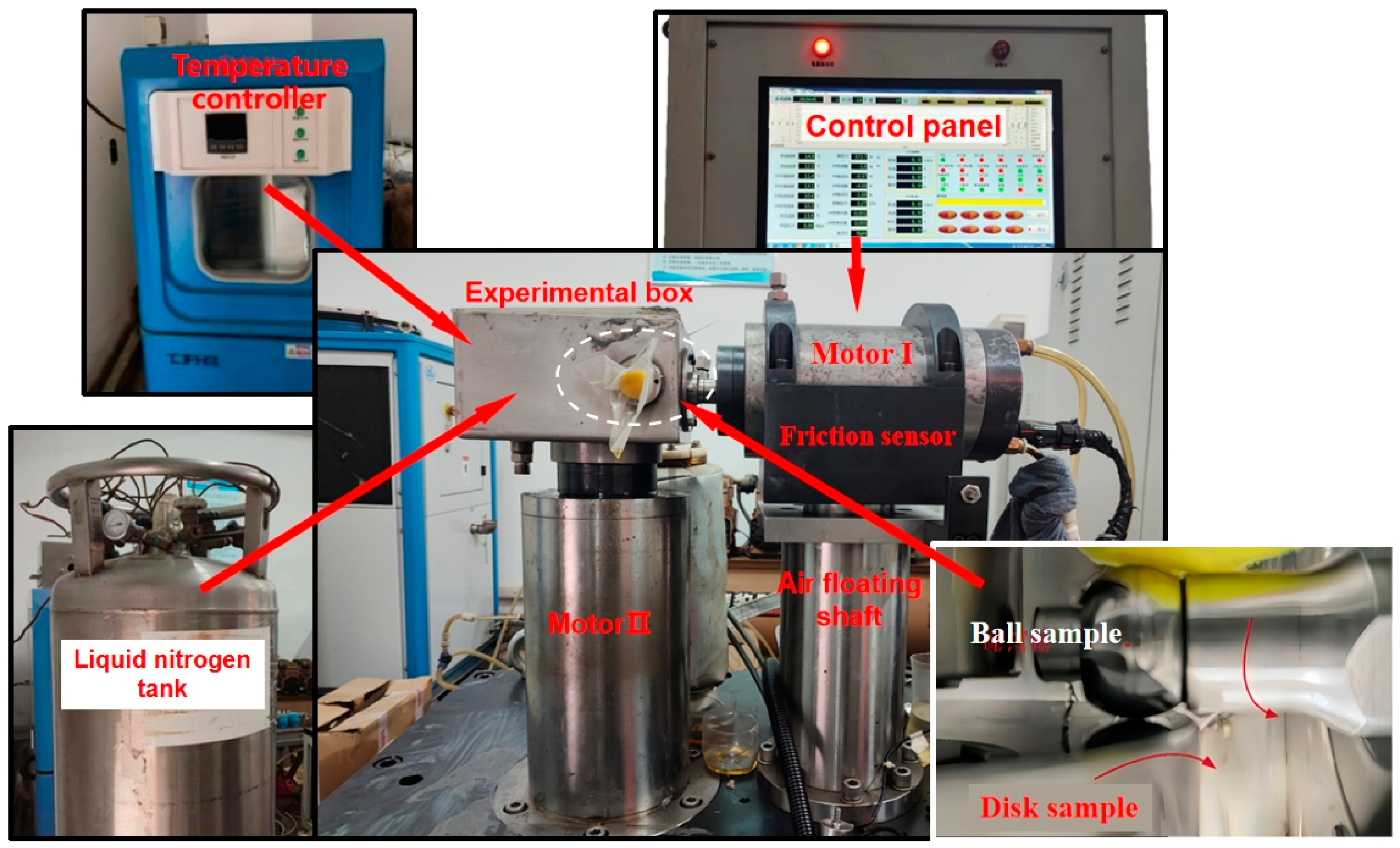
To further investigate the ultra-low temperature traction characteristics of bearing materials, the ball–disc friction and wear testing machine developed by Henan University of Science and Technology, as shown in
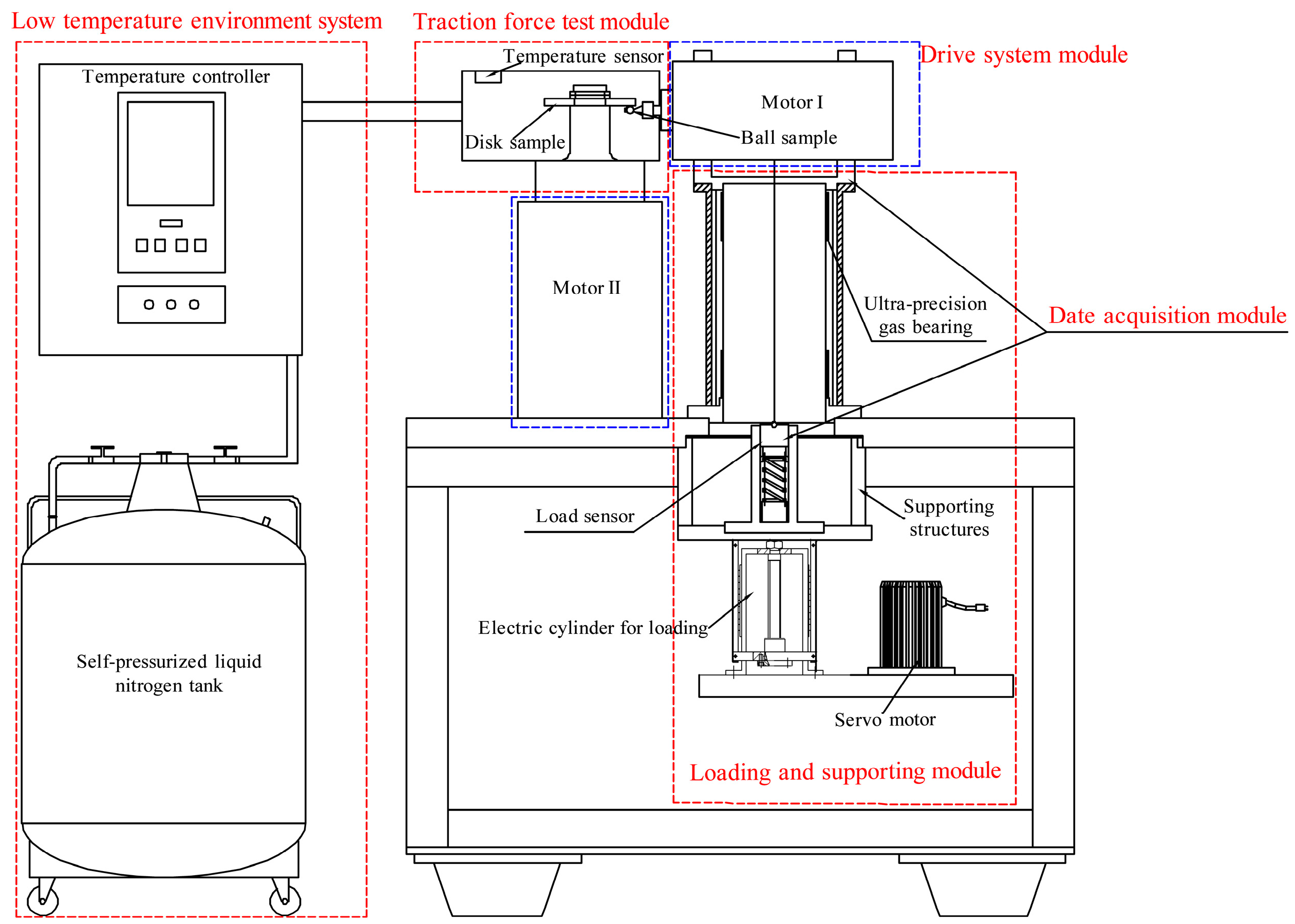
Figure 1. The structure diagram of the testing machine is shown in
Figure 2. The Gupta solid slip model [
31] was used to fit the traction coefficient. Equation (1) represents the traction coefficient as a function of the sliding speed:
where
is the traction coefficient;
A,
B,
C, and
D are the constant coefficients that have no physical significance; and
is sliding speed.
Prior to this, other scholars conducted relevant research [
28], and, on this basis, I selected different working conditions to study the traction coefficient of solid-lubricated bearings in a nitrogen environment. The ball–disc testing machine was employed to determine the traction coefficient (
) of MoS
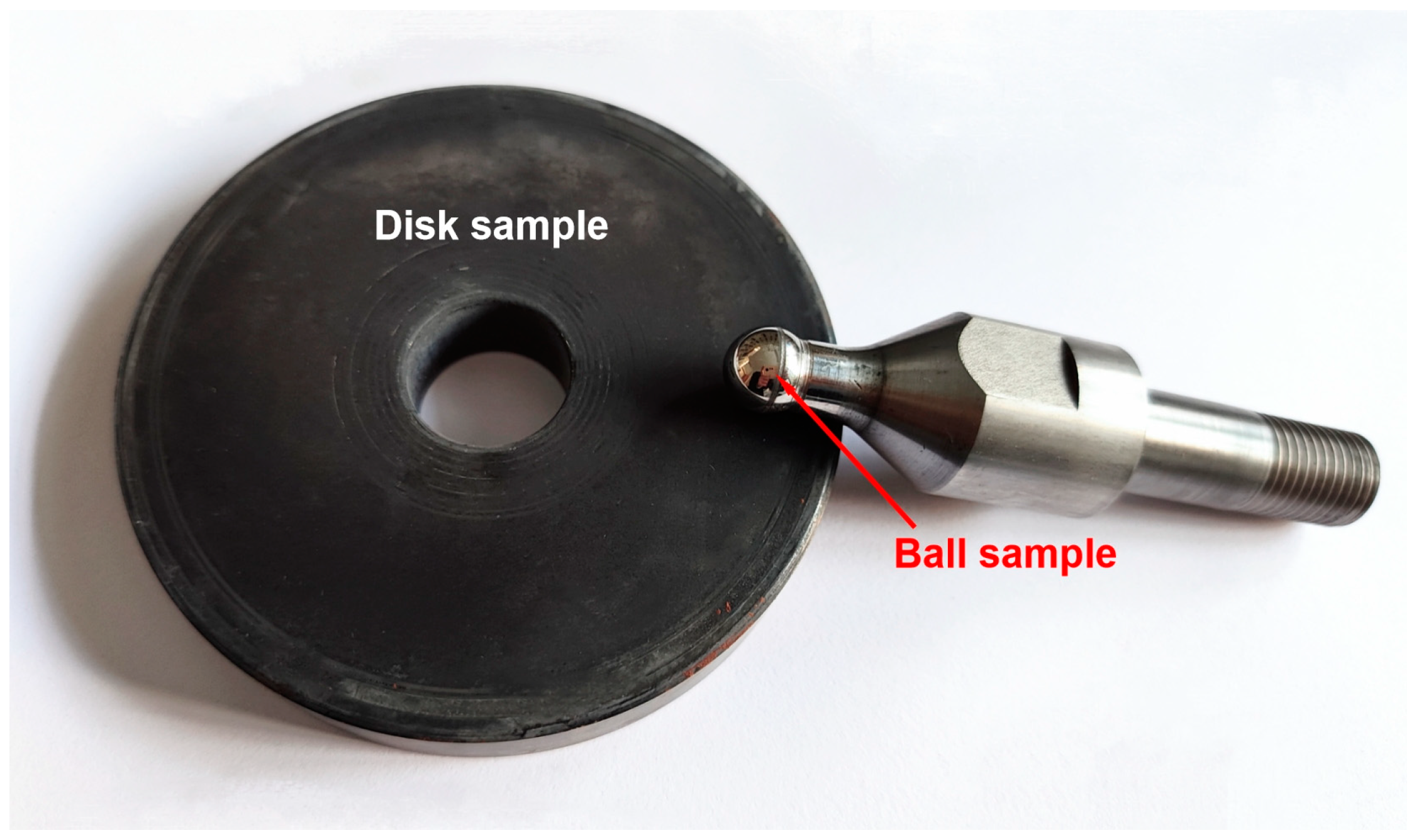
2 solid lubricant under various working conditions. The disc samples are covered with solid lubricating coatings, as shown in
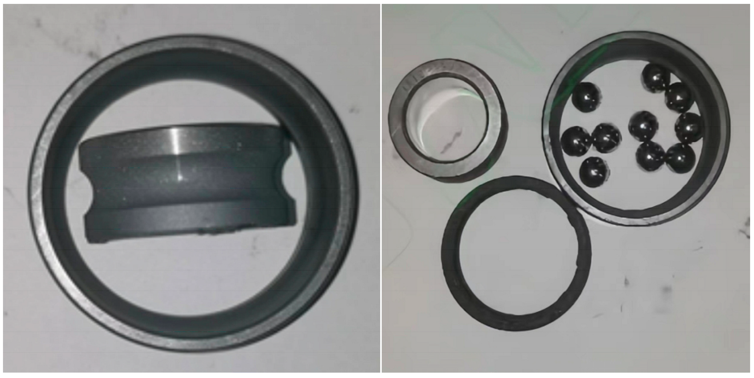
Figure 3. The accuracy level of the ball was G10. A complete bearing coated with MoS
2 is shown in
Figure 4, where the MoS
2 film has a jet-black color, no matte and a soft texture [
12]. When the spraying process is completed, the outer ring is heated to assemble the bearing parts.
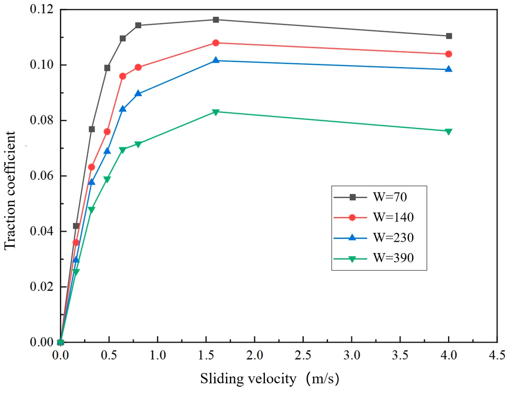
The ambient temperature of the ball and disc working area is −175 °C to −170 °C. The nominal load between the ball and disk sample is 70 N, 140 N, 230 N, and 390 N, and the sliding speed is . Select the ball and disk sample sliding velocity for 0.0 m/s, 0.16 m/s, 0.32 m/s, 0.48 m/s, 0.64 m/s, 0.8 m/s, 1.6 m/s, and 4 m/s.
As shown in
Figure 5, the traction coefficient of the MoS
2 coating changes with the sliding speed. The overall trend of the traction coefficient is that it first increases and then slightly decreases with the increase in sliding speed. The traction coefficient decreases with the increase in load.
To facilitate the calculation of traction parameters, the traction equation is obtained by introducing the dimensionless parameters, such as Equation (2).
where
is a dimensionless parameter;
is the equivalent elastic modulus;
R is the equivalent radius of curvature. The coefficients of
A,
B,
C, and
D and the dimensionless parameter
with the approximate exponential function relationship between them.
The Gupta solid slip model was fitted using the least squares method. By compiling the Matlab program of least squares, the optimal values of the mathematical model coefficients
A,
B,
C, and
D are listed in
Table 1.
The Gupta solid slip model was used to fit the experimental data, and the fitting values of corresponding coefficients with a strong correlation were selected and brought into Equation (2) for regression analysis. The correlation coefficients are greater than 0.95, indicating good fitting accuracy. The comparison between the traction coefficient fitting value and the test value is in
Figure 6.
The results indicate that the calculated values of the traction coefficient equation derived from the Gupta model closely match the actual test values, with an error range of less than 10%. This suggests that the Gupta solid slip model accurately predicts the ultra-low temperature traction coefficient.
3. Bearing Dynamics Modeling
Based on the dynamic theory of rolling bearings, this section analyzes the forces and motion states of balls and cages of solid-lubricated ball bearings. Combined with the traction coefficient model, the nonlinear dynamic differential equations of solid-lubricated angular contact ball bearings are derived and established to analyze the dynamic performance of the cage.
3.1. Establish the Bearing Coordinate System
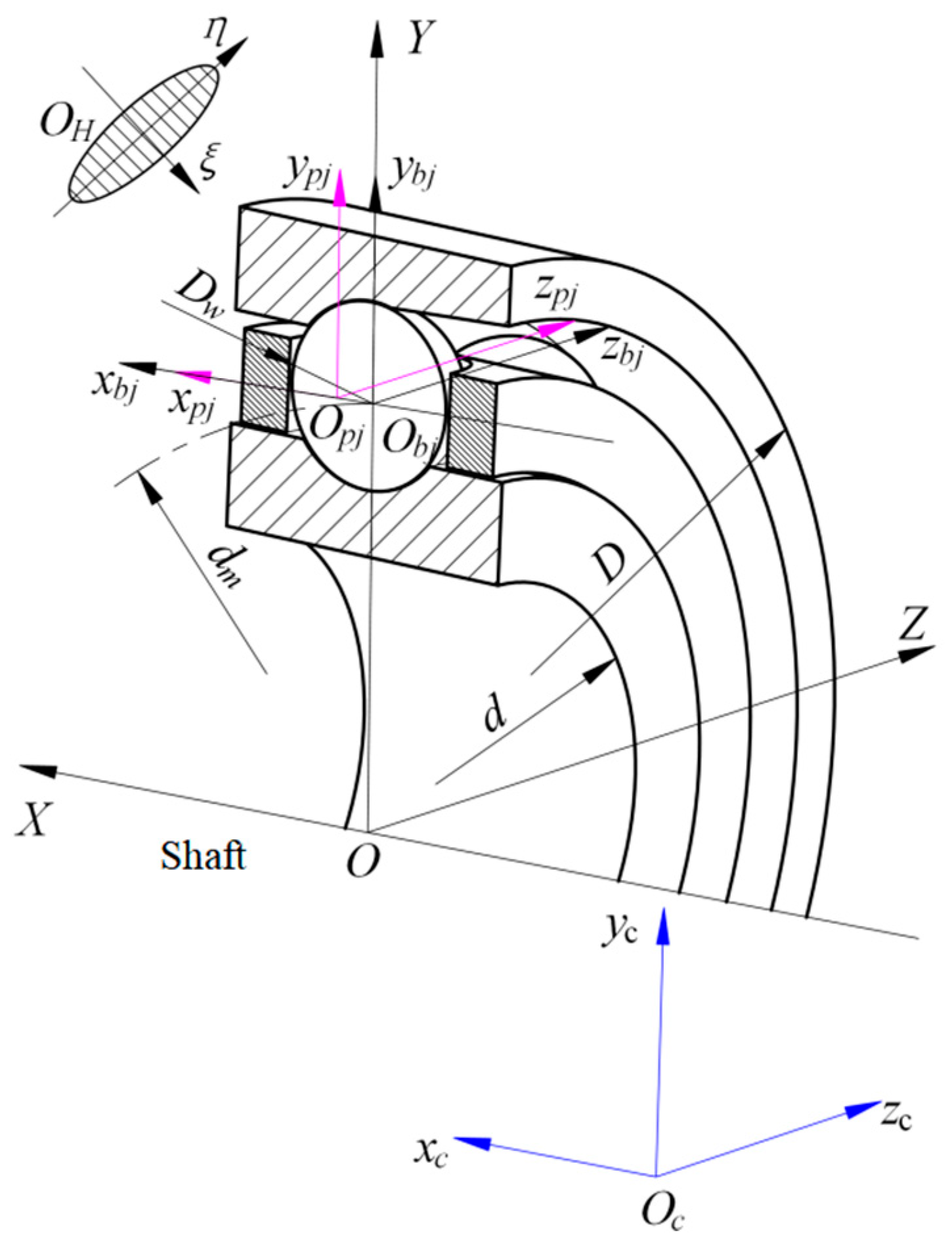
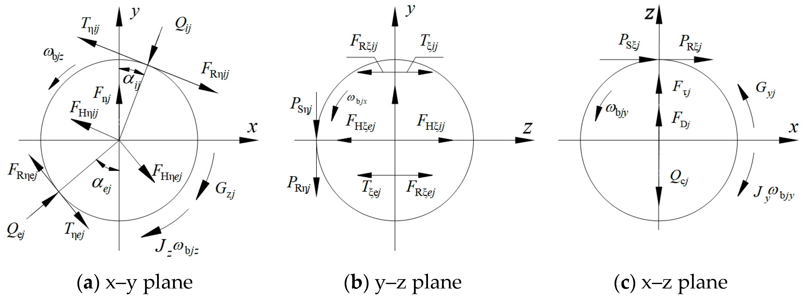
In order to accurately and clearly describe the motion and force state of each component, the azimuth, force, torque, velocity, acceleration, and other parameters of each element are transformed into the inertial coordinate system by coordinates to establish a bearing dynamics model, as shown in
Figure 7.
is a coordinate system fixed in space, and point O coincides with the center of mass of the cage. The X-axis is parallel to the axial direction of the bearing.
is the centroid coordinate system of the ball, and point coincides with the center of mass of the ball. The -axis is parallel to the X-axis.
is the local coordinate system of the contact surface, and point is located in the center of the contact area. The -axis is the contact elliptical minor axis, which follows the rolling direction of the steel ball. The -axis is the contact elliptical major axis, which points to the inside of the compressed part. The i represents contact with the inner ring, and the e represents contact with the outer ring.
is the centroid coordinate system of the cage, and point coincides with the center of mass of the cage. The -axis is parallel to the axial direction of the bearing.
is a coordinate system of cage pocket holes, and point coincides with the center of the hole where the j-th ball is located. The -axis is parallel to the -axis.
3.2. Cage Force Analysis
3.2.1. Normal Force between Ball and Cage Pocket
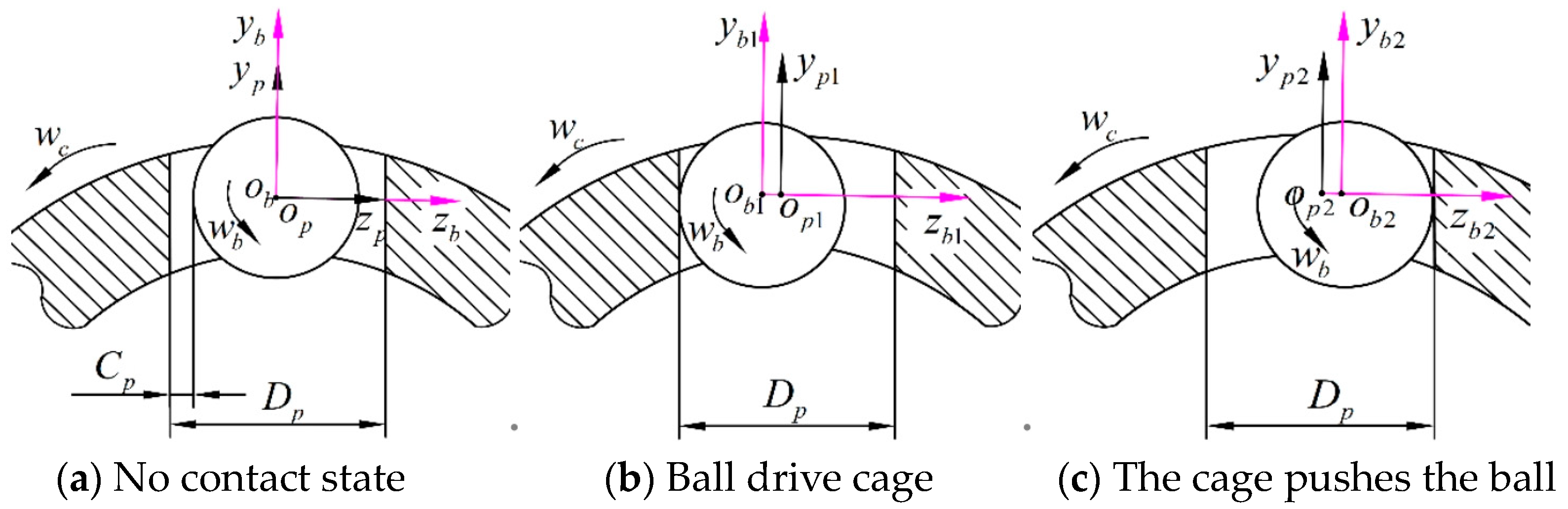
Figure 8 illustrates the three motion states of the ball and cage. The calculation process for determining the normal force associated with the center displacement is described in reference [
32].
Where is the rotation of the ball, is the rotation of the cage, is the cage pocket hole clearance, and is the diameter of the cage pocket hole. When coincides with , the steel ball is in no contact with the cage. When is ahead of , the ball drives the cage to rotate. When lags behind , the cage pushes the ball to rotate.
3.2.2. Friction at the Contact Surface between the Ball and the Pocket
When the bearing is operating, it will generate rolling friction (
) and sliding friction (
) in the contact zone. Part of the calculation equation is as follows, and the detailed calculation method is shown in the reference [
33].
where
is the auxiliary parameter,
is the average velocity of the ball and the surface of the cage pocket hole in the
direction,
is the average velocity of the ball and the surface of the cage pocket hole in the
direction,
is the radius of curvature of the ball and the surface of the cage pocket hole in the
direction,
is the radius of curvature of the ball and the surface of the cage pocket hole in the
direction, and
and
are auxiliary parameters, which can be solved by
.
3.2.3. Force between Cage and Ring Guide Surface
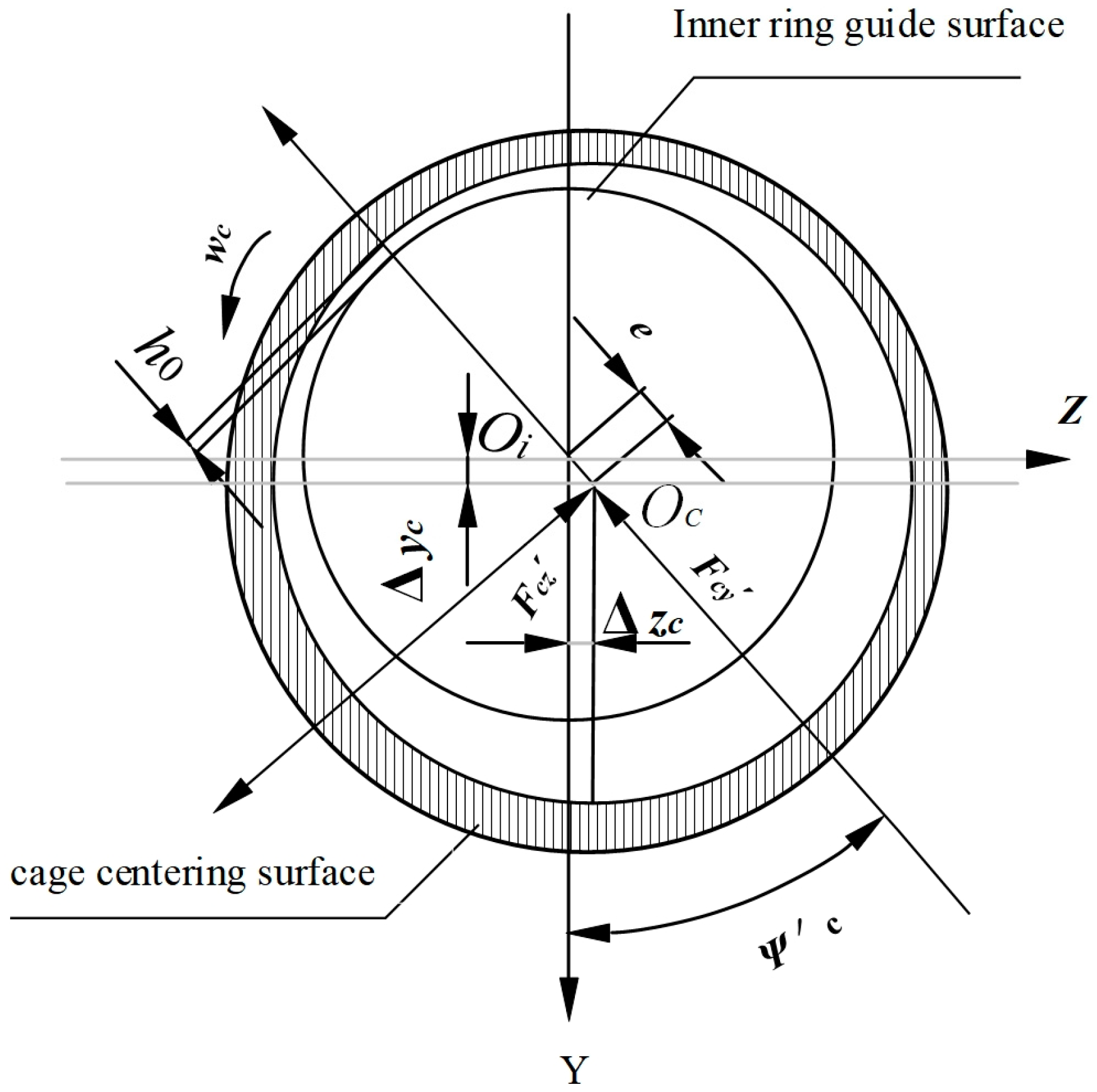
During the operation of the solid-lubricated ball bearing, the gap between the cage’s inner cylinder surface and the ring guide surface will create pressure.
Figure 9 shows the interaction of the guide surface and the cage, and the movement guidance of the cage is the inner ring guidance.
The force
generated by solid-lubricating film pressure can be described by decomposition into
and
[
33]. The forces in the normal and tangent directions are denoted, respectively.
is where the minimum oil film thickness is located, rotate
is the angle relative to the inertial axis
, and
is the angular velocity of the cage around the x-axis of the inertial coordinate system.
is the displacement deviation between the center of mass of the cage and the center of mass of the inner ring.
3.3. Differential Equation of Ball
Figure 10 shows the stress situation of the ball, and the equilibrium equation of the ball can be obtained as follows:
Equation (4) represents the variables used in the analysis. Where refers to the mass of the ball; represent the acceleration components for the ball; for ball angular velocity; or ball angular acceleration; for the revolution of the ball speed; represents the moment of inertia of the ball; are the moment of inertia components of the ball in the inertial coordinate; are the components of the moment of inertia during the motion of the steel ball in the inertial coordinate system; are the friction forces in the contact entrance area between the steel ball and the raceway; are the traction force in the direction of the and axis of the contact between the ball and the inner and outer raceways; are all horizontal components of force acting on the center of steel ball; are the sliding friction forces on the surface of steel balls; are the rolling friction forces on the steel ball surface; are the inertial force component during the movement of the steel ball; is the aerodynamic resistance of the gas to a single steel ball; and is the collision force between the steel ball and the cage.
3.4. Differential Equation of Cage
In this study, the cage guidance method is inner ring guidance, and the force balance equation is as follows:
is cage quality;
is the position angle of the
j th s ball;
is the diameter of the bearing pitch;
are cage acceleration;
are cage three principal moments of inertia;
are cage angular velocity;
are the cage angular acceleration; and
is the components of the collision force between the ball and the cage in the inertial coordinate system, respectively. For the calculation of dynamic differential equations of inner and outer rings, see reference [
34].
4. Cage Stability Analysis Method
The movement of the cage is complex, and its stability is often assessed based on the shape of its centroid trajectory. A point trajectory indicates complete stability, while a single circle or periodic circle trajectory suggests a stable vortex state. When the cage centroid trajectory is polygonal, or even chaotic, it indicates that the centroid of the cage is divergent and in an unstable vortex state [
35,
36].
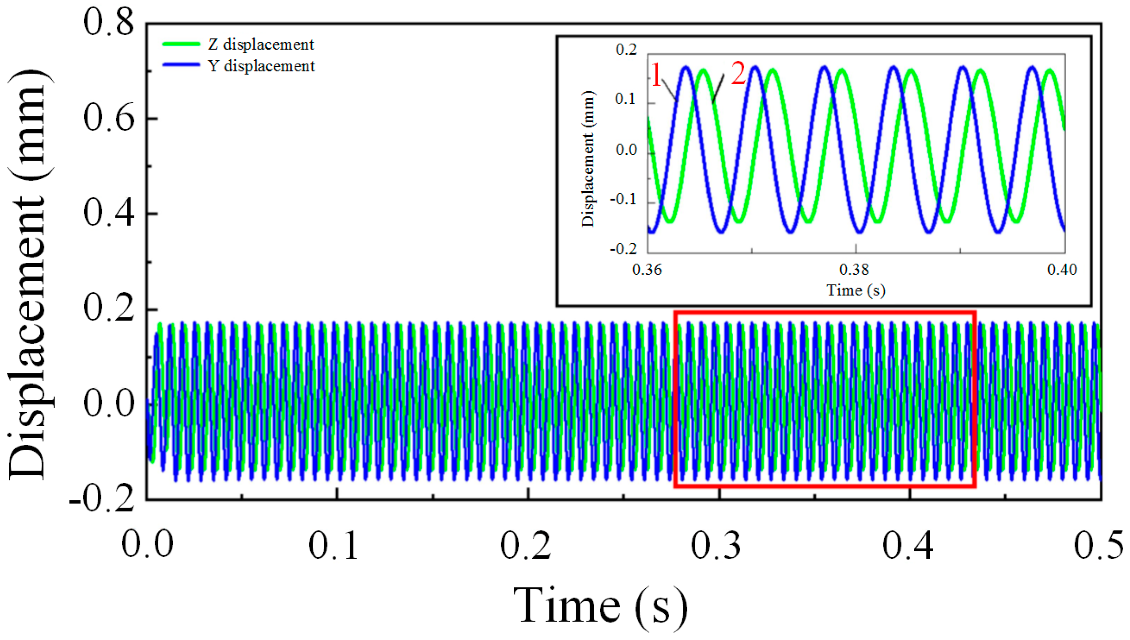
Figure 11 shows the variations in centroid vibration displacement of the cage in the Y and Z directions during time-domain analysis under constant load conditions obtained from dynamic simulation analysis. Curve 1 represents the displacement in the y-direction, while curve 2 represents the displacement in the Z-direction. The figure illustrates that as the cage vortex moves, the radial displacement of the centroid changes periodically over time, with the Z displacement leading to the Y-direction displacement. On this basis, the dynamic performance of a solid-lubricated ball-bearing cage is analyzed in the next section.
To quantitatively analyze the cage when the centroid trajectory exhibits a vortex rather than a point, the change in centroid vortex speed can be combined to assess the stability of the cage. In the actual optimization design analysis, the instability of the cage movement is determined by calculating the ratio of the deviation in centroid vortex velocity.
The stability of the cage is determined by comparing the deviation of the centroid vortex velocity, as proposed by Ghaisas, et al. [
23]. The ratio of the standard deviation of the centroid velocity to the average value can be calculated as follows:
is the vortex velocity of the centroid of the cage at different moments;
is the cage centroid average speed. The larger the ratio of the centroid vortex velocity deviation and the greater the change in the vortex velocity, the worse the stability of the cage is, and vice versa.
In the next section, the stability of the cage under inner ring guidance is analyzed by changing operating parameters such as axial load and radial load, as well as structural parameters such as the radial internal clearance, cage pocket gap, and guide gap, and the dynamic performance of the cage is discussed from the aspects of the cage centroid trajectory and the traction characteristics between the ball and the cage.
5. Analysis of Factors Affecting Cage Stability
5.1. Validation of the Cage Analysis Model
The model of the test bearing is 7204AC. The initial basic parameters and working conditions of the bearing are shown in
Table 2. The bearing ring and ball are made of G95Cr18 material, and the surface is coated with MoS
2 film, while the cage is made of nylon 66. The material characteristics of nylon 66 are listed in
Table 3.
In this paper, the classical example of Gupta [
37,
38] is used to verify the reliability of the proposed model. Gupta analyzes the stability of solid-lubricated high-speed angular contact ball-bearing cages. Although the results of the cage stability obtained by the model are slightly different from those calculated by Gupta, the overall trend is consistent, which is caused by the different parameters of cage material and lubricant.
As can be seen from [
38], the cage mass center orbit shape derived from the Gupta analysis is consistent with the results of the later sections of this paper. As the cage mass center whirl velocity at the center of mass of the cage increases, the force between the cage and the guide surface also increases. The comparison and analysis of the above results prove that the results calculated in this paper have certain accuracy and reliability. On the basis of the Gupta analysis model, a variety of structural parameters and working condition parameters are added to analyze the stability of the cage more comprehensively.
5.2. Influence of Axial Load on Cage Stability
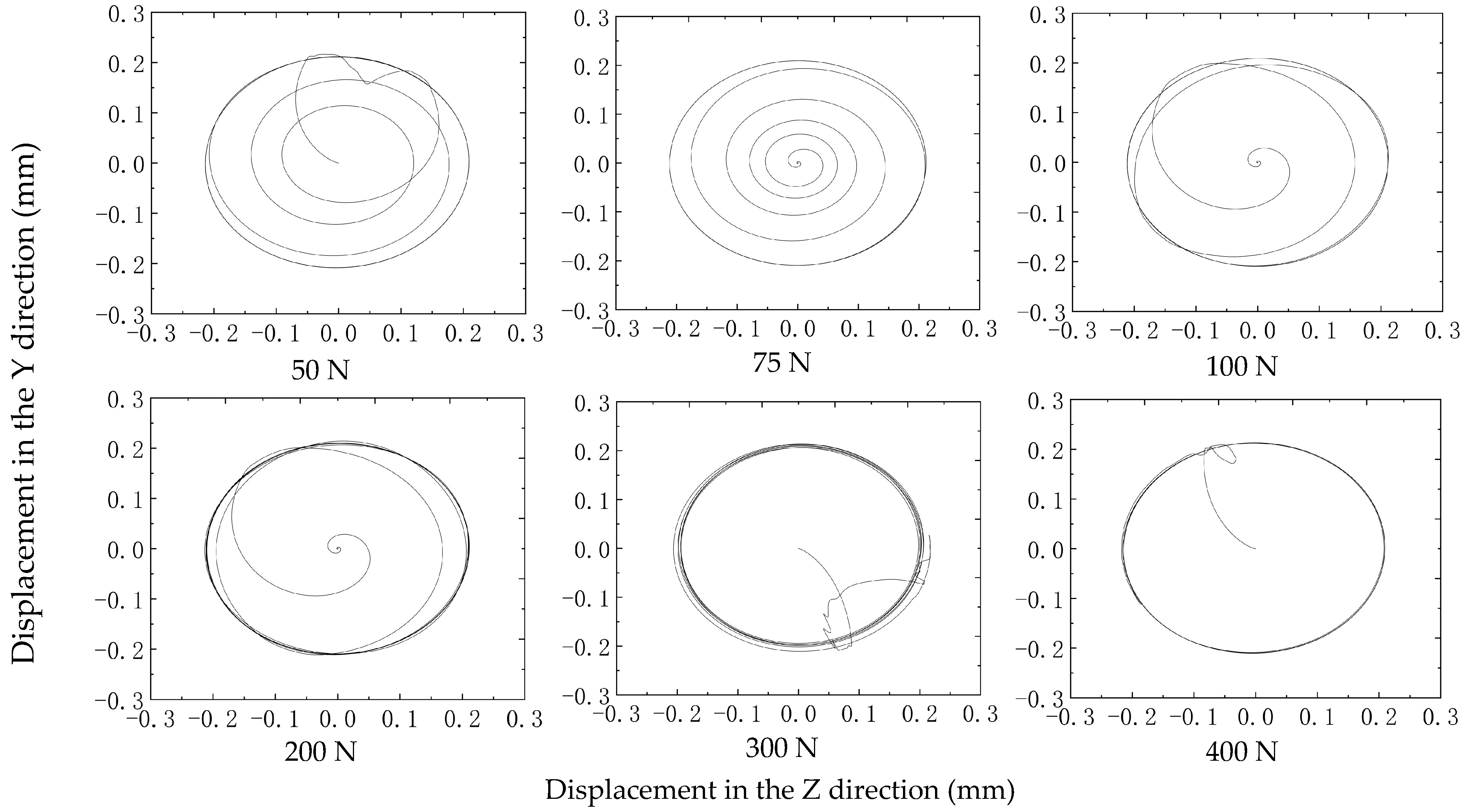
Assuming the angular contact ball bearing used in the rotor system of axial load working condition had a rotating speed of
= 20,000 r/min, a radial load of
= 0 N, and axial loads of 50 N, 75 N, 100 N, 200 N, 300 N, and 400 N, respectively, the relationship between the centroid trajectory of the cage and the axial load is shown in
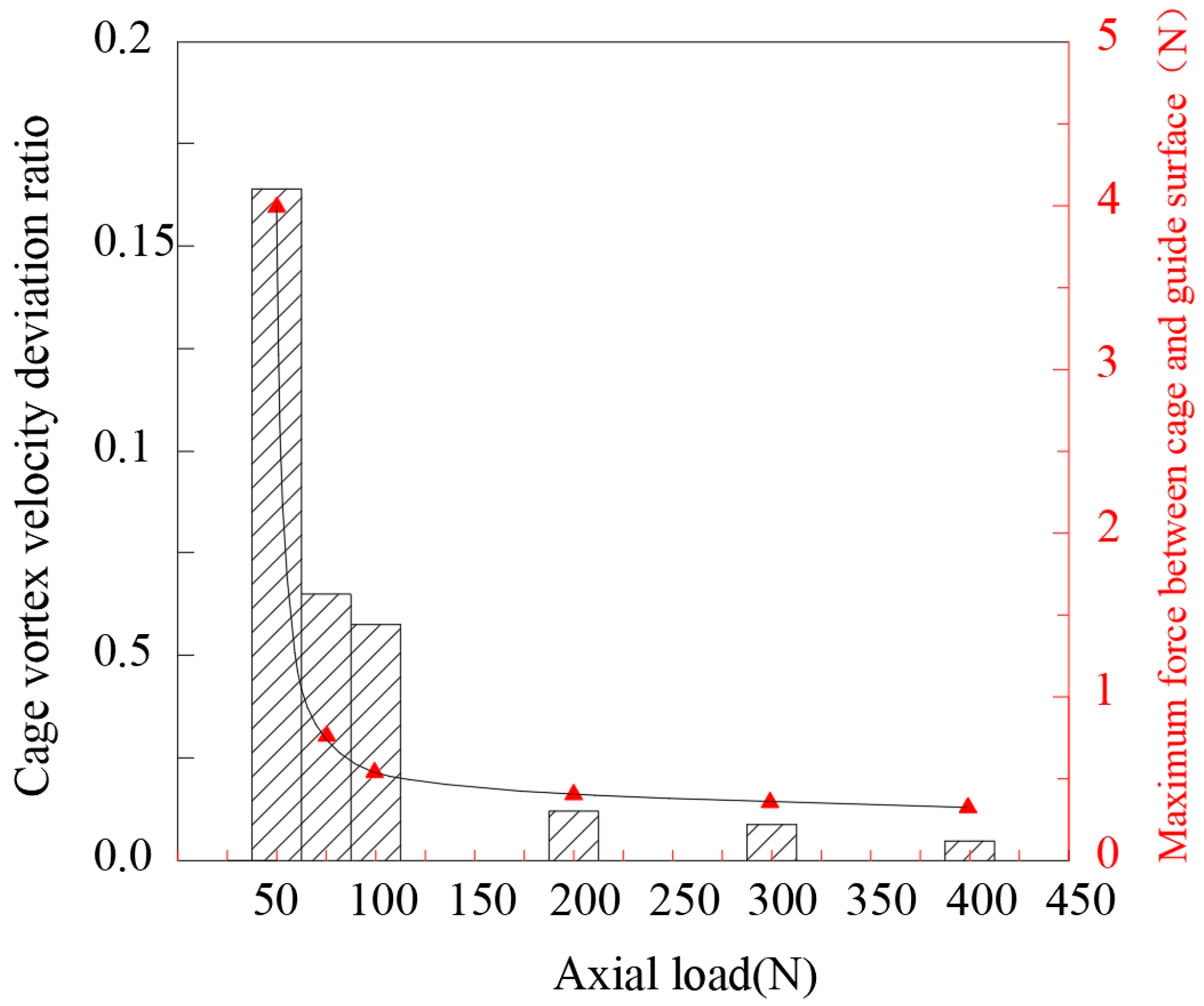
Figure 12. The calculated speed deviation ratio of the bearing cage and the maximum force between the cage and the guide surface of the ring vary with the axial load, as shown in
Figure 13.
The maximum force between the cage and ring guide surface decreases with the increase in axial load. This is mainly because the traction coefficient of a solid lubricant decreases with the increase in load. In
Figure 5 of
Section 2, it can be observed that the traction effect of the raceway on the ball weakens, leading to a reduction in the collision between the ball and the cage. The cage is guided by the inner ring, and the guiding force of the ring on the cage tends to remain stable. Therefore, within the range of 50 N to 400 N axial load, the cage remains stable, and the vortex velocity deviation ratio also tends to stabilize.
5.3. Influence of Radial Load on Cage Stability
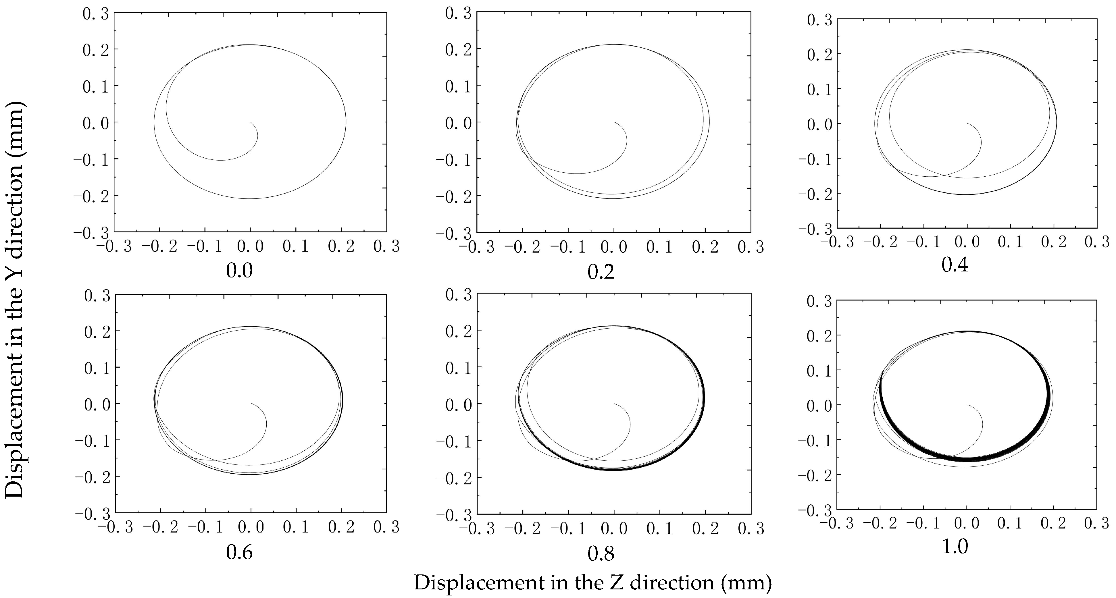
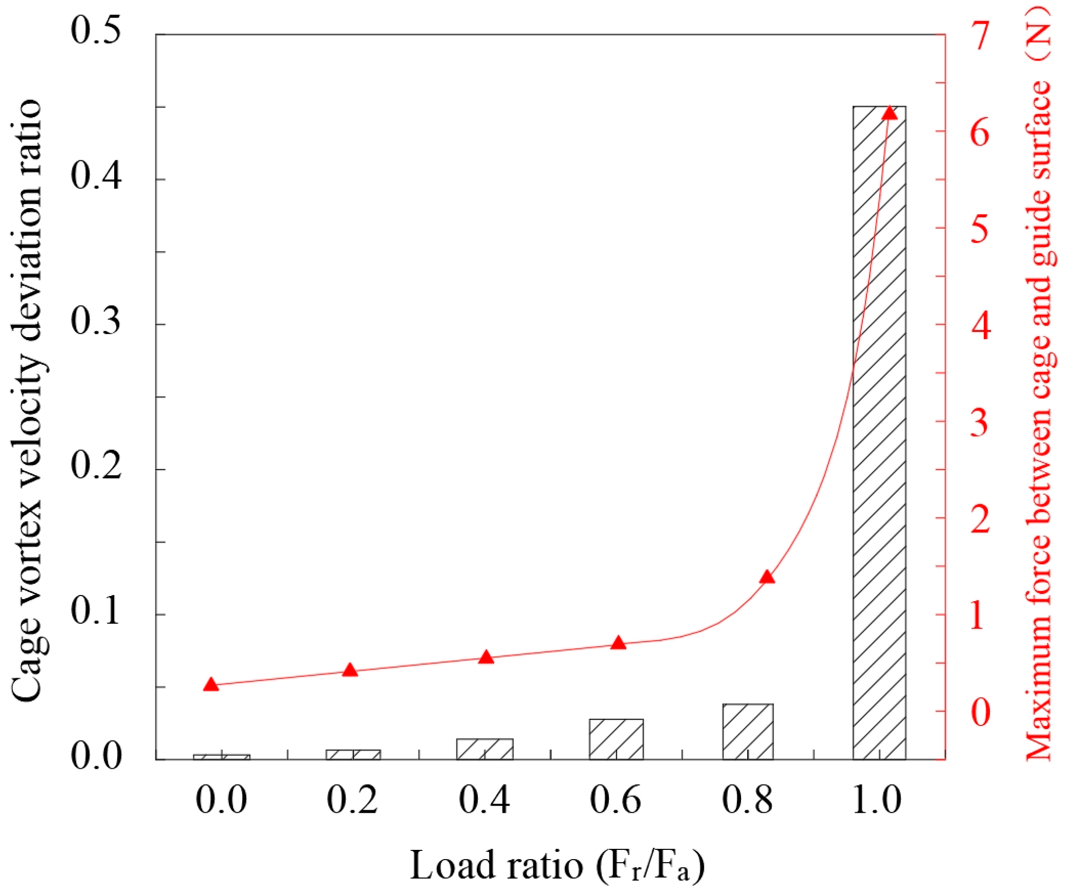
Angular contact ball bearings are under combined loading, and this section assumes that the bearing ring speed for
= 20,000 r/min and
= 2000 N for radial load, respectively, 0 N, 400 N, 800 N, 1200 N, 1600 N, and 2000 N. The centroid trajectories under different load ratios are shown in
Figure 14. The calculated cage vortex velocity deviation ratio and the maximum force between the cage and the guide surface of the ring vary with the radial load, as shown in
Figure 15.
The main reason for the cage movement characteristics shown in the figure is that when the bearing is subjected to a combined load, the load distribution of the balls becomes increasingly uneven with an increase in radial load. This uneven load distribution leads to a significant difference in the generation of traction force on the ring, resulting in a substantial change in the collision force between the ball and the cage pocket at different azimuth angles, which will cause the collision between the ring guide surface and the cage, and, ultimately, reduce the stability of the cage.
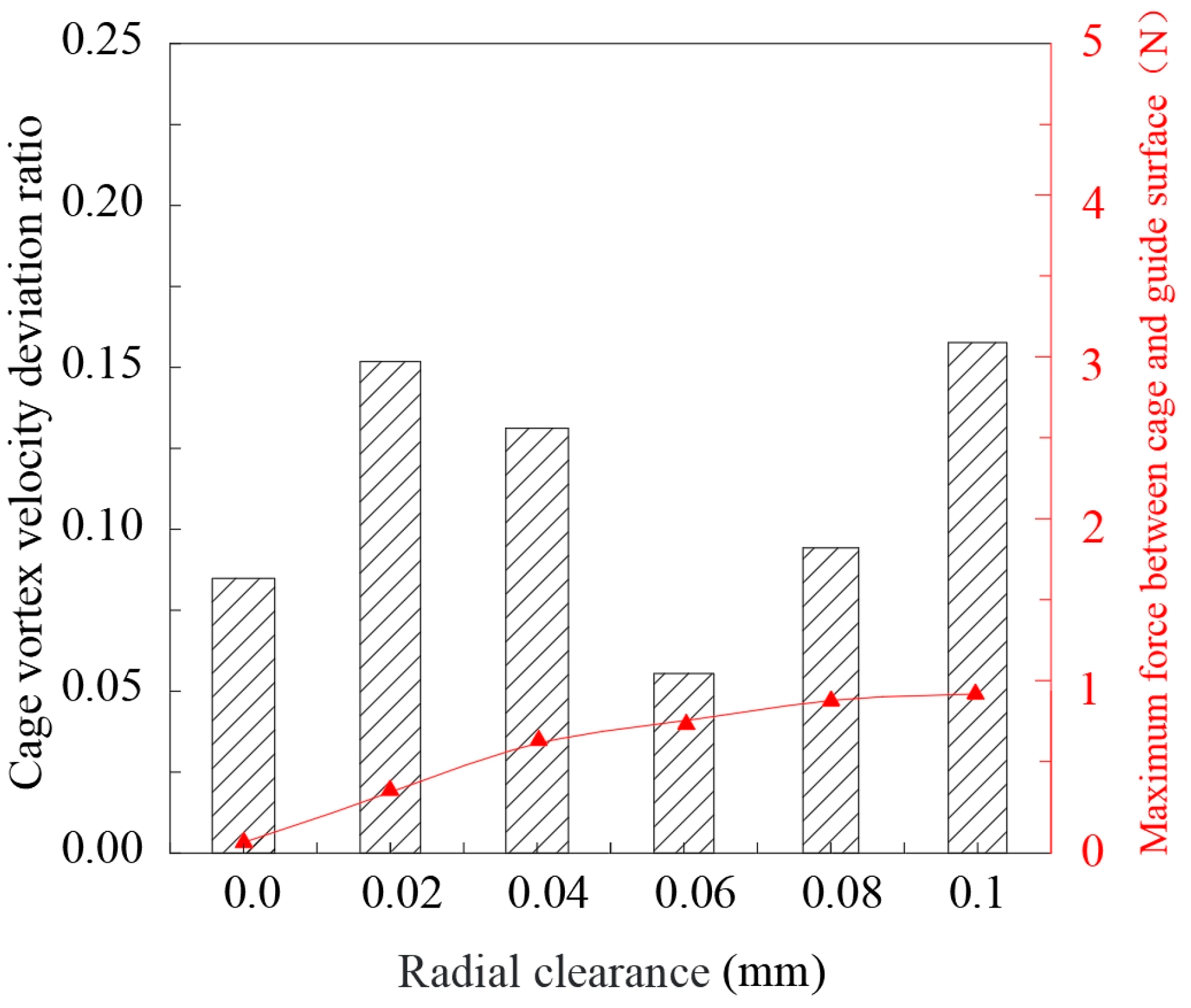
5.4. Influence of Radial Internal Clearance on Cage Stability
The influence of the initial radial internal clearance on the dynamic performance of the cage was studied when the cage pocket gap was 0.24 mm and the guide gap was 0.40 mm. With a bearing speed of
= 20,000 r/min,
= 2000 N and
= 800 N conditions, as shown in
Figure 16 and
Figure 17, the velocity deviation ratio of the cage centroid and the maximum force between the cage and the guide surface of the ring change with the radial internal clearance.
The results presented in
Figure 17 demonstrate that the deviation ratio of the centroid vortex velocity initially increases, then decreases, and, eventually, increases with the increase of radial internal clearance. Although there is no clear linear relationship between the stability of the cage and the change in clearance, within the selected range of clearances, the lowest deviation ratio of the vortex velocity of the centroid and the smallest range of the centroid’s trajectory circle when the radial internal clearance is 0.06 mm.
The force between the cage and the ring guide surface remains relatively constant as the radial internal clearance changes, indicating that the clearance has minimal influence on this force.
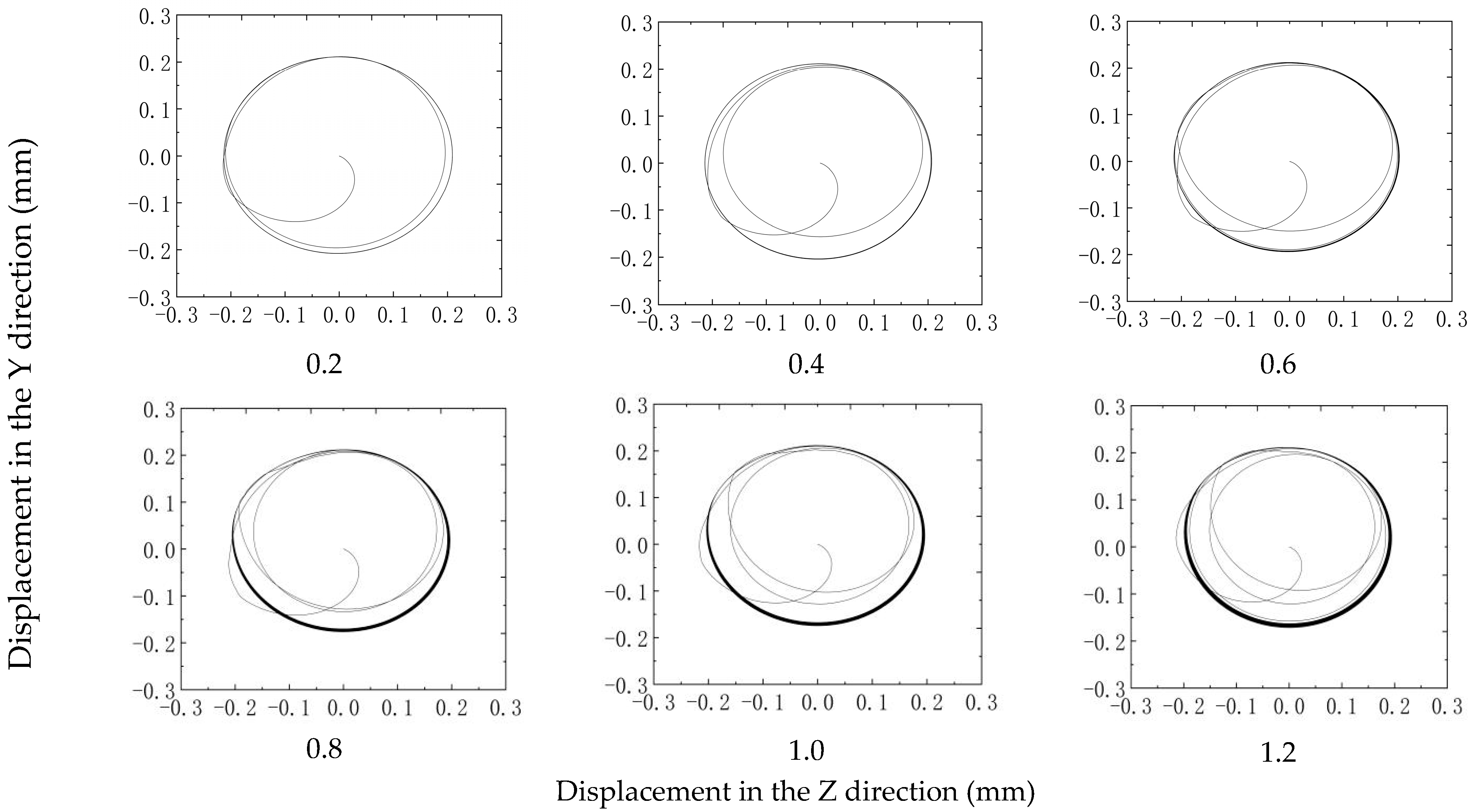
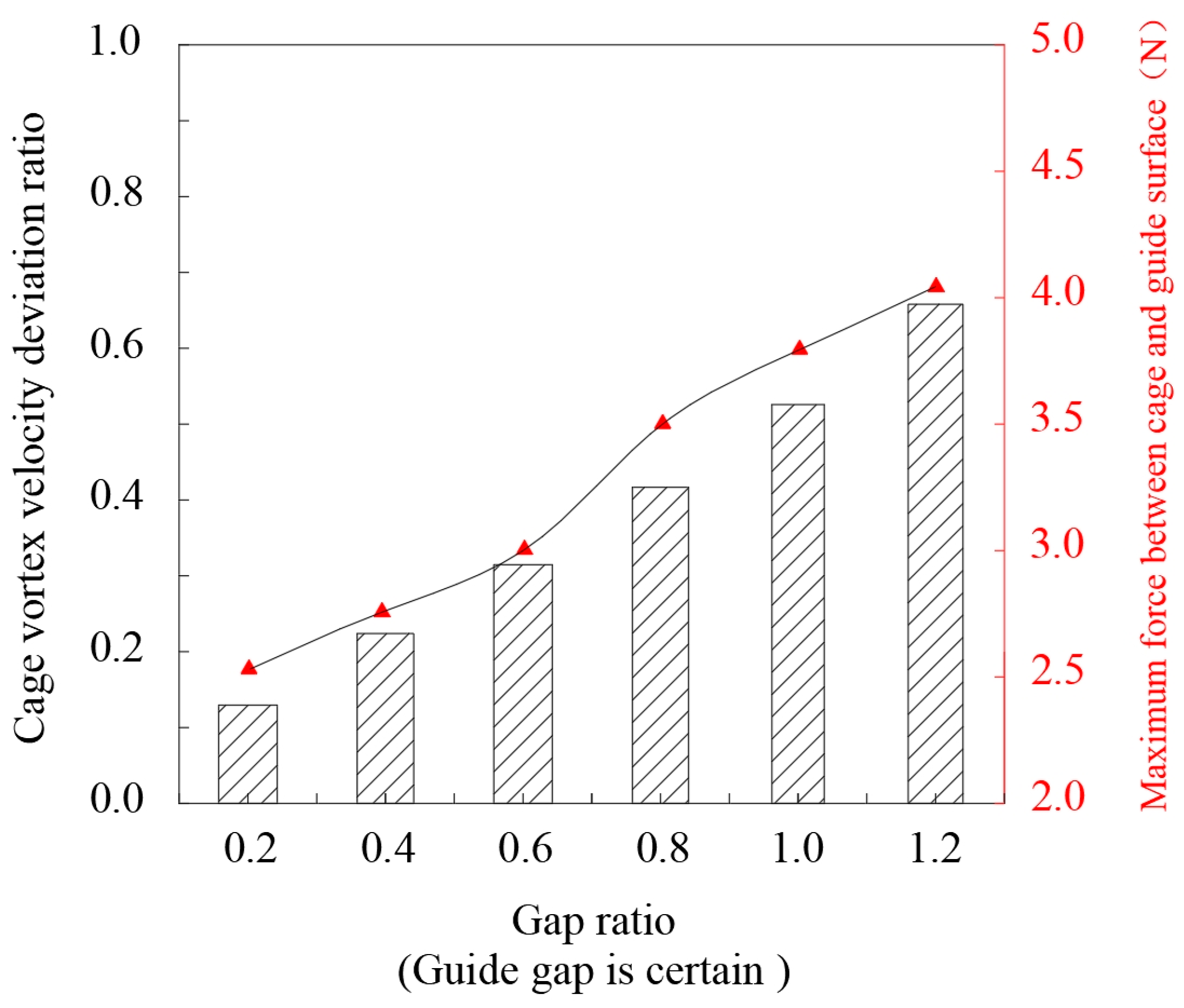
5.5. Influence of Guide Gap Change on Cage Stability
When the cage pocket gap is 0.24 mm and the gap ratio (the ratio of the cage pocket gap to the guide gap) ranges from 0.2 to 1.2, the bearing condition for speed is
= 20,000 r/min,
= 2000 N and
= 800 N, the influence of the guide gap on the cage stability is studied, as shown in
Figure 18 and
Figure 19. Extract the cage of the centroid velocity deviation ratio, cage and ring guide surface maximum force changing with the guide gap.
The primary cause of the cage’s unstable movement is attributed to the gradual decrease in the guide gap and the subsequent reduction in the movement range of the centroid of the cage as the gap ratio increases. As a result, the collision between the ring and the cage obviously increases vibration, and the motion stability of the cage gradually deteriorates.
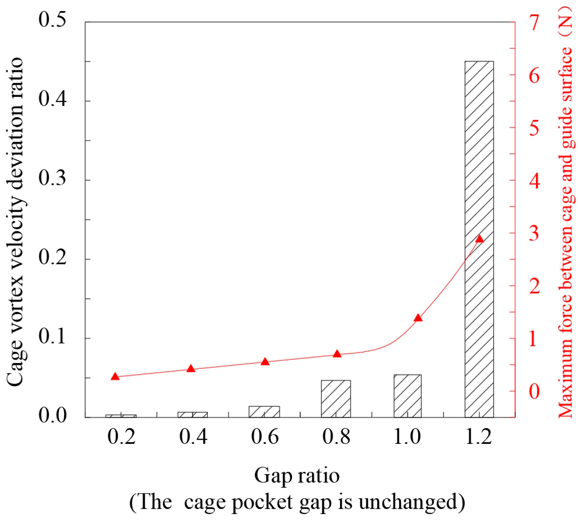
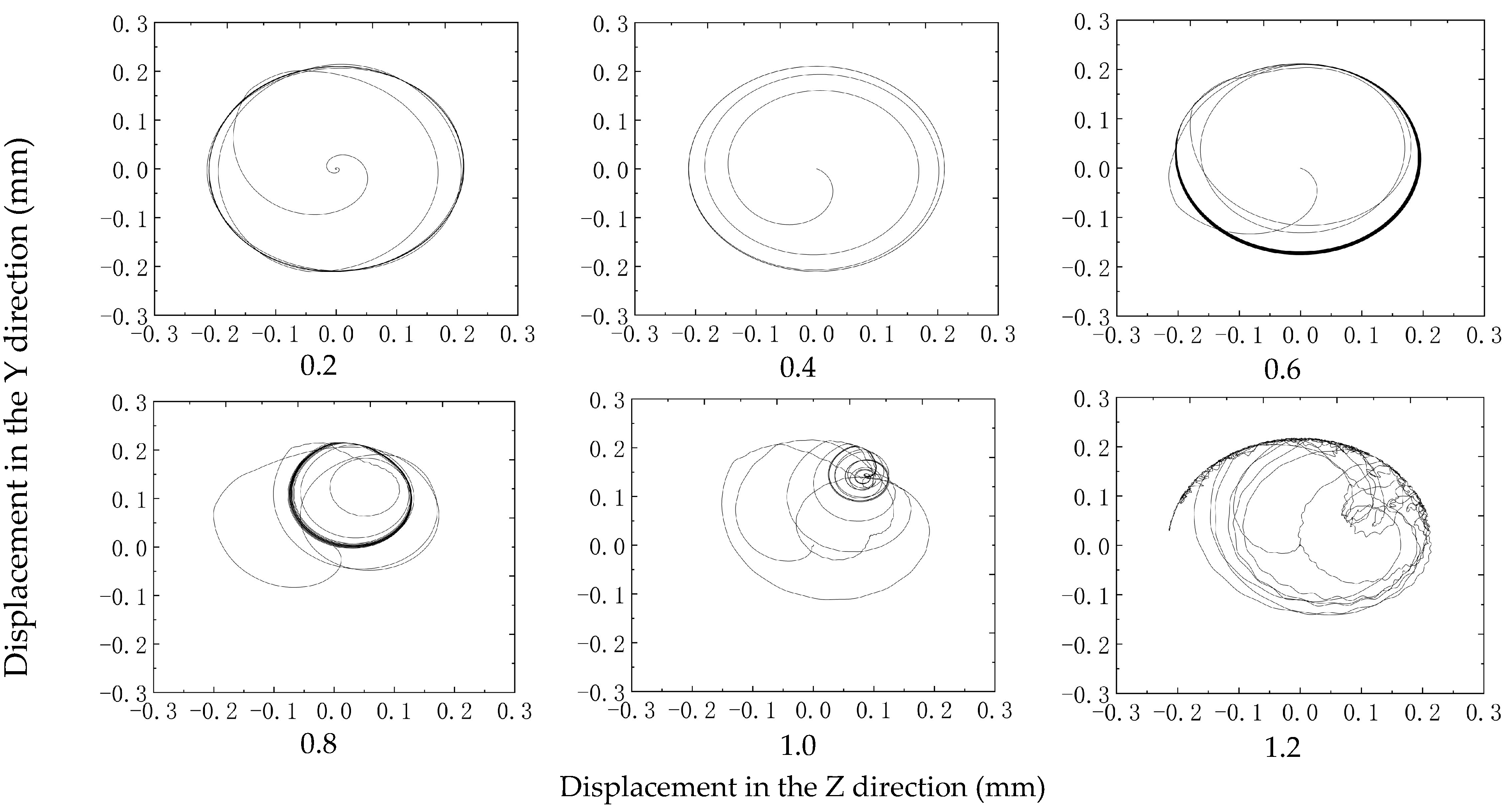
5.6. Influence of Cage Pocket Gap Change on Cage Stability
When the guide gap is 0.40 mm and the gap ratio (the ratio of the pocket gap to the guide gap) varies from 0.2 to 1.2, the influence of the change of pocket gap on the stability of the cage is studied. Under the conditions of an axial force of 2000 N, radial force of 800 N, and rotation speed of 20,000 r/min, extract the velocity deviation ratio of the cage centroid, cage, and ring guide surface maximum force changing with guide gap, as shown in
Figure 20 and
Figure 21.
The main reason for the unstable movement of the cage is the decrease in the guide gap as the gap ratio increases. This leads to a decrease in the movement range of the cage’s centroid and causes obvious collisions between the ring and the cage, resulting in increased vibration and weakened motion stability of the cage. Therefore, it is important to pay attention to the matching between the cage pocket gap and the guide gap in the design of the cage, ensuring that the cage remains in a stable vortex state to improve the reliability of bearing applications.


