Abstract
This study investigated the frictional properties of HPMC under different load and concentration conditions through friction experiments and surface characterization. The study aimed to explore and reveal the influence of load and concentration on the frictional properties of HPMC, as well as its anti−wear mechanism. The results of the study indicated that under the same solution concentration, the effect of load on the friction coefficient of HPMC was not significant. Specifically, for samples with low concentration (C−0.2), the wear ratio of HPMC under a 4 N load (1.01 × 10⁻¹¹ mm3·N−1·m−1) was significantly lower than the wear ratio under a 2 N load (1.71 × 10⁻¹⁰ mm3·N−1·m−1). The orientation−driven formation of graphite−like carbon nanosheets, initiated by the decomposition of HPMC short chains, created a tribofilm−containing organic−chain mixed nanosheet on the sliding contact surface, which prevented direct contact between the upper and lower friction pairs. This achieved the anti−wear mechanism of two−body wear (tribo−film of an mDLC−coated ball and tribo−film of a GLC−coated Si wafer), ultimately leading to a state of ultra−low wear at the interface. The excellent anti−wear performance of HPMC suggests its potential as a candidate for the next generation of environmentally friendly bio−based solid lubricants.
1. Introduction
Friction and wear, which can cause serious damage to component surfaces, considerable energy consumption, and significant economic losses, have been regarded as the most urgent problems to be solved in modern industry. According to statistics, friction and, thus, induced wear constitute a large proportion of global energy consumption and component failures, which has become the main bottleneck restricting the reliability of current equipment and the development of a high−end manufacturing industry [1,2,3]. With the gradual improvement of environmental awareness worldwide and the continuous strengthening of government policies on environmental protection, the development of green solid lubricants has received widespread attention. Traditional lubricants contain a large number of harmful chemicals, such as lead, which can pose a significant threat to the ecological environment and human health. Green solid lubricants can replace traditional lubricants to a certain extent, reduce the use and release of toxic substances, reduce environmental pollution, and protect nature and human health. In addition, green solid lubricants can be degraded or recycled, reducing resource consumption, energy emissions, and maintenance costs. As a common raw material for the green processing industry, cellulose is a naturally renewable, biodegradable, and environmentally friendly polymer compound, as well as one of the most widely distributed and abundant polysaccharides in nature [4,5,6]. With the rapid development of green industrial technology, scholars are gradually deepening their research on cellulose processing by exploring the intrinsic properties of cellulose. At present, there is a wide range of cellulose types available, such as dietary fibers, hydroxypropyl methylcellulose (HPMC), and lignin fibers [7,8,9]. Among them, HPMC is commonly used as the raw material or filler additive and is highly susceptible to rubbing against the inner wall of the barrel, which can lead to wear and tear of the inner wall, with excellent film−forming and hydrophilic properties [9,10,11]. Accordingly, a series of preliminary explorations on the tribological properties of cellulose have been carried out by pioneer researchers to help achieve the reduction of friction and wear via surface design.
The exceptional wear resistance of HPMC, combined with its ability to maintain long−term wear stability under high loads, makes it a highly sought−after material in various industries. Its environmentally friendly solid−lubricant properties further enhance its appeal, making it a versatile option for use in different environmental conditions. With HPMC, companies can rely on a durable and efficient solution for reducing wear and extending the lifespan of their equipment, ultimately saving time and money in the long run. Its exceptional properties make it a valuable investment for any business looking to improve performance and longevity in its operations. In previous studies, HPMC [12,13] was shown to be an effective lubricant that can reduce the friction coefficient and protect the underlying material from wear through tribological experiments. Specifically, the reduction of both friction coefficients and wear rates of the silicon wafers coated with HPMC exceeded more than 50% compared with that of pure silicon wafers. This can be attributed to the fact that HPMC possesses outstanding film−forming properties and a degree of evenness, i.e., when the HPMC coating on the wafer surface undergoes abrasion, a transfer layer can be formed at the interface under the action of friction force to reduce the friction coefficient and effectively protect the silicon substrate. The above studies show that HPMC possesses remarkable friction−reducing and anti−wear capabilities and has the giant potential to become a new type of industrial lubricant material. However, up to now, the research on the influence and regulation of HPMC tribological properties is still insufficient. So far, only the thickness has been explored for its influence on the tribological properties of HPMC by Shi et al. [13]. The main factors known to affect the friction and wear of cellulose include environmental atmosphere, sliding speed, load, concentration, etc. Among them, concentration has been considered to be one of the important factors in characterizing the scale of cellulose. In addition, the wear mechanism and tribological behavior of raw materials or fillers in the extruder have also been suggested to be closely related to the external loads at which the machine operates [14,15,16]. Nevertheless, the influences of concentration and load on the lubrication performance of HPMC are rarely discussed in the previous studies, and the underlying mechanism is still unclear. So, further in−depth investigations are urgently needed for the realization and mastery of the low friction and wear of HPMC.
In this study, the friction−reducing and anti−wear performance of HPMC were explored by a ball−on−disc tribometer operating in a linear reciprocating mode under air conditions. The multilayered diamond−like carbon (mDLC, has higher hardness than standard DLC) and graphite−like carbon (GLC, has good anti−friction and −wear compared with standard DLC) films, which are both inert amorphous carbon films that can effectively isolate the direct contact between the counterparts in the friction process [17], are coated on the surfaces of the upper (steel ball) and lower (Si substrate) counterpart, respectively. The tribo−couples made up of carbon−based films have weak tribological performances (their friction coefficients are above 0.1, and wear ratios are above 10−6 mm3/(N·m) in the common conditions) in the previous research [18]. The aim of this study is to investigate how concentration and load impact the tribological properties of HPMC in carbon−based films. By understanding the wear mechanisms of HPMC, we hope to provide valuable insights for enhancing the tribological performance of this material. Ultimately, this research can offer theoretical and technical recommendations for optimizing the use of HPMC in tribology, thus expanding its potential applications in engineering.
2. Experimental Section
2.1. Materials and Methods
Graphite−like carbon (GLC) films, and multilayered diamond−like carbon (mDLC) films were prepared by ion vapor deposition, which was reported in our previous work. [19] The surface roughness of the GLC−coated steel ball and the mDLC−coated disc is 22 nm [20]. Hydroxypropyl methylcellulose (HPMC) powders with 100 mPa·s of concentration were purchased from Shanghai Aladdin Bio−Chem Technology Co., Ltd. (Shanghai, China). Isopropyl alcohol (IPA) was purchased from Shanghai Aladdin Bio−Chem Technology Co., Ltd.
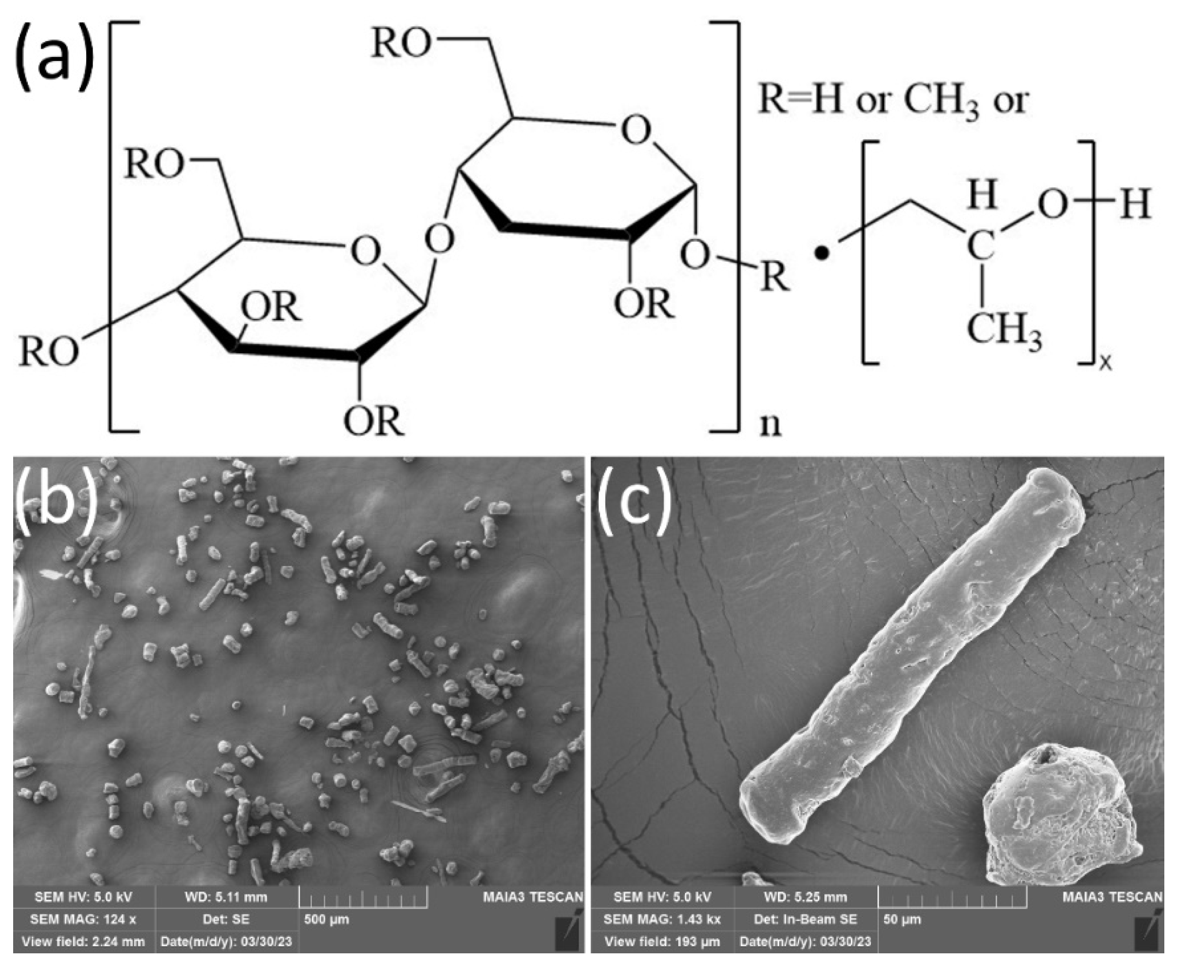
For the preparation of modified GLC films, there were two steps as follows. (1) Fifty mg HPMC powders were dissolved in 250 mL IPA under ultrasound for 60 min and short−range distillation for 10 min; after still standing for 4 h in the sealed environment, the supernatant liquid was removed by pipette from the mixed solution to obtain the HPMC solution (named C−0.2, 0.2 is the weight ratio of HPMC to IPA). Meanwhile, the high ratio of the HPMC solution was named C−10, with 100 mg HPMC powders and 10 mL IPA, which was referred to in the preceding step. (2) Finally, the HPMC solution was added slowly to immerse the whole surface of the GLC films in the ambient environment. These samples were then stored at room temperature to form HPMC coatings until the solution was volatilized, leaving HPMC deposited on the surface of the GLC film. The chemical structure and microstructure of HPMC are shown in Figure 1. To ensure the uniformity and reproducibility of the HPMC coating on the surface, the following measures can be taken. (1) To ensure the uniformity of the HPMC coating, first of all, it is necessary to control the concentration of the coating solution, and secondly, to ensure that the HPMC coating can be slowly and with unchanging drops deposited on the substrate surface. (2) To ensure the reproducibility of the HPMC coating, it is necessary to ensure the ambient temperature and humidity of the preparation, that is, the same day and the same time period.

Figure 1.
(a) Chemical structure and (b,c) microstructure of HPMC.
2.2. Characterizations
The tribo−tests−were carried out in air at room temperature via a ball−on−disc tribometer (Bruker UMT−3 platform) operating in a linear reciprocating mode at room temperature under an atmosphere environment (temperature of 25 ± 2 °C and relative humidity of 20−30%). The GLC film−coated silicon wafers (15 × 15 × 1 mm3 in size) were clamped upon a rotating sample platform to be tested. Simultaneously, the bare and GLC−coated bearing steel balls (diameter = 6.0 mm) were performed on as counterparts, respectively. In our experiments, the normal load was set to 2 N and 4 N at 2 Hz for reciprocating frequency, with repeating the amount experiments three times, respectively, and the stroke distance was set to 4 mm. The calculated initial maximum Hertz contact pressure of 0.71 GPa and 0.9 GPa was obtained, respectively. The computational formula of Hertz contact pressure is listed as follows:
In the equation, σmax (GPa) represents the maximum Hertz contact pressure, P (N) represents the normal load, E (GPa) represents the elasticity modulus, and R (mm) represents the radius of the frictional ball.
For the surface morphology and structure, 3D white−light interference topography (ZYGO NewViewTM 8000, ZYGO NewView, Oklahoma City, OK, USA) and an optical microscope (Nikon optical microscopy, Nikon, Melville, NY, USA) were used for the characterization of the targeted surface morphology before and after the tribo−tests. The equation calculates the wear rates the ball scar and disc track allow:
Here, S means the cross−section of the wear track derived from 3D white−light interference topography for a square millimeter unit; L means the stroke distance derived from the ball−on−disc tribometer for a millimeter unit; F means load set from the ball−on−disc tribometer for Newton unit; C means the whole stroke distance derived from the ball−on−disc tribometer for a meter unit. The unit of wear rate is mm3·N−1·m−1.
The structures of contact surfaces are detected via Raman spectra before and after the tribo−tests. Raman spectra were collected by a Horiba Jobin−Yvon HR800 system with an Ar+ laser of 514.5 nm wavelength. After tribo−testing, the contact centers of the ball scar and the wear track are the detection focus.
For the interfacial structure, after tribo−testing, the contact surface is cut by an electron beam to obtain laminated specimens. The focused ion beam–scanning electron microscope (SEM/FIB, FEI Quanta 3D FEG, FEI Company, Hillsboro, OR, USA) dual−beam system equipped with the function of low−kV Ga+ ion milling was conducted for preparing lamellar samples. Before FIB −milling, a protective Cr layer in the ion sputtering system was first coated on the contact surfaces, and a thick Pt supporting layer successively, which could prevent the frictional contact interface from implanting artifacts and structural damage. After tribo−testing, to accurately analyze the cross−sectional structures of the tribofilms via a high−resolution transmission electron microscope (HRTEM, JEOL−2010F, JEOL, Tokyo, Japan) operating at 200 kV, the thickness of lamellar samples was kept below 100 nm. The energy−dispersive X−ray spectra (EDS, JEOL−2010F) equipped in the HRTEM were utilized to detect elemental mappings.
3. Results and Discussion
3.1. Tribological Behaviour
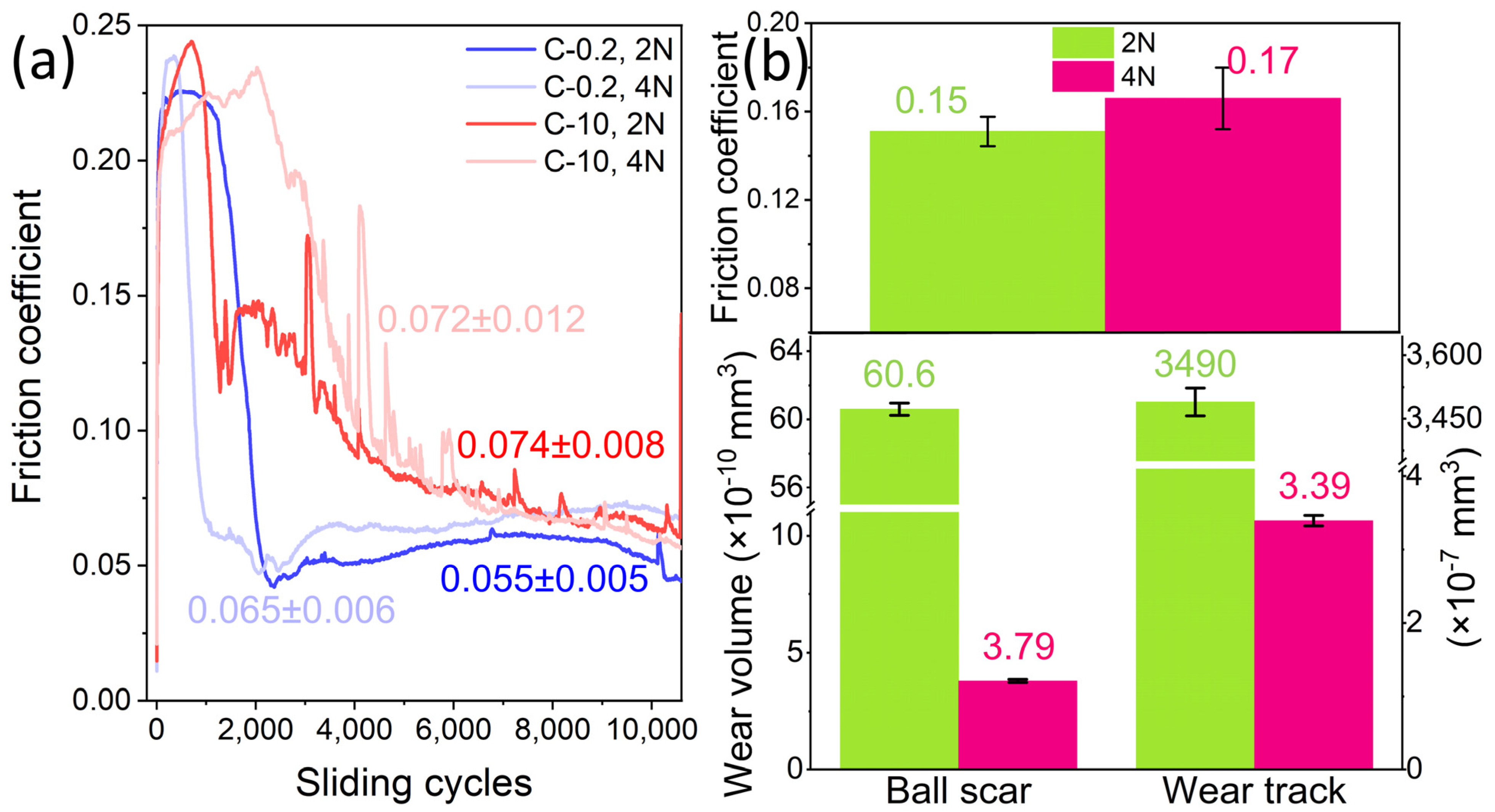
The 2 N and 4 N loads, corresponding to initial maximum Hertz contact stresses of 0.71 GPa and 0.90 GPa, respectively, are shown in Figure 2a, along with the friction coefficient–−sliding cycles plot of HPMC coated on a GLC silicon surface and a DLC−coated steel ball. It can be observed that the changing trend of all curves is generally similar. That is, the friction coefficient increases rapidly to a peak in the initial sliding stages, then drops abruptly, and finally reaches a steady state after the running−in stages of 2351 (C−0.2, 2 N), 1225 (C−0.2, 4 N), 4078 (C−10, 2 N), and 4393 (C−10, 4 N) cycles. The results show that, under the same load, the friction coefficient of low concentration (i.e., C−0.2) HPMC is smaller, and the average friction coefficient of all conditions is below 0.1, reaching the range of ultra−low friction. It is worth noting that, at a load of 2 N (0.71 GPa) in a C−0.2 system, the friction coefficient of HPMC is the smallest, μ = 0.055 ± 0.005, approaching ultralow friction (μ below 0.1) or ultralow wear (wear ratio below 10−7 mm3/(N·m) [21,22,23,24]). In the uncoated tribological systems, the friction coefficients and wear ratios were all above 0.1 and 10−7 mm3/(N·m), as shown in Figure 2b. Therefore, it can be considered that the type of friction pair can also significantly affect the frictional performance of HPMC in tribological tests. In addition, under the same solution concentration, the influence of load on the friction coefficient of HPMC is not significant. Specifically, for the low−concentration samples(C−0.2), the friction coefficient of HPMC under a 2 N load (μ = 0.055 ± 0.005) is lower than the friction coefficient under a 4 N load (μ = 0.072±0.012).

Figure 2.
Friction testing data of (a) coated and (b) uncoated friction pairs. (a) Friction curves of HPMC with different concentrations (C−0.2 and C−10) tested under different 2 N and 4 N normal loads. (b) Friction coefficient and wear ratio of uncoated friction pairs.
In experiments involving friction, the 3D white−light scanner is utilized to analyze the micro−morphology and texture of an object’s surface. This includes assessing surface roughness, convexity, and overall surface quality. By examining and comparing topographical data from various surfaces, researchers can uncover the origins and development of friction. Furthermore, this analysis can assist in evaluating the wear resistance and condition of friction surfaces. Figure 3 illustrates the wear rate of HPMC and the 3D white−light interference morphology after wear under different loads (2 N and 4 N) in C−0.2 and C−10 systems. It can be observed that all samples achieved an ultra−low wear rate, especially for the HPMC sample in the lower friction pair, which exhibited a wear rate as low as 10−10~10−11 mm3/(N·m), indicating a nearly zero wear state [25]. From the three−dimensional white−light interference morphology in Figure 3, it is also evident that the base scratches and ball wear marks after wear are relatively small (with the maximum depth of the base scratches at the level of 0.01 um and the maximum wear radius of ball wear marks at the level of 53 um, with a wear rate range of 10−11~10−7 mm3/(N·m)). Particularly for the base, except for slight scratches on the contact surface and its vicinity (with the depth of base scratches ranging from 0.01 um to 0.001 um), the rest of the surface morphology appears smooth. It is speculated that the excellent wear resistance of HPMC can primarily be attributed to its good film−forming ability and scratch self−healing capability, where HPMC forms a transfer film at the contact interface under the action of frictional force to effectively protect the silicon substrate. This has been confirmed in previous studies [12].
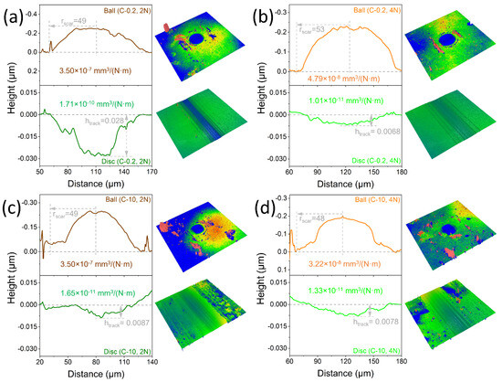
Figure 3.
The wear ratios of friction pairs coated with different concentrations of HPMC (C−0.2 and C−10) tested under different normal loads (2 N and 4 N). (a) C−0.2 tested under 2 N, (b) C−0.2 tested under 4 N, (c) C−10 tested under 2 N, and (d) C−10 tested under 4 N.
Comparing the tribological results, we found that the variation of the friction coefficient with an increase in load is not significant (Figure 2a). However, the wear rate of the contact surface decreases significantly with an increase in load. For example, in C−0.2, the wear rate of the lower friction pair decreased from 1.71 × 10⁻¹⁰ mm3/(N·m) to 1.01 × 10⁻¹¹ mm3/(N·m), almost reaching an order of magnitude; in C−10, the wear rate of the upper friction pair decreased from 3.5 × 10⁻⁷ mm3/(N·m) to 3.22 × 10⁻⁸ mm3/(N·m), also almost reaching an order of magnitude. This indicates that HPMC exhibits stronger wear resistance under high loads (0.9 GPa) and long loading cycles (>10,000 cycles). Furthermore, under the same load conditions, as the concentration of HPMC increases, the difference in wear resistance on the surface is reduced. This suggests that, when the HPMC concentration reaches a critical point, the wear resistance is maximized. This is also related to the ability of HPMC molecular chains to move when subjected to frictional forces. In previous studies2, it was found that a polymer molecular weight that is too high can lock the molecular chain movement, leading to lubrication failure and significant wear. Similarly, a high HPMC concentration can also restrict molecular chain movement, leading to microdeposit, with minimal impact on further improving the wear resistance under high loads.
3.2. Anti—Wear Morphologies
Optical microscopy and Raman spectroscopy play crucial roles in analyzing friction surfaces. Optical microscopy allows us to observe the contact between surfaces during friction, leading to a better understanding of the friction mechanism. On the other hand, Raman spectroscopy provides valuable insights into the chemical composition, physical state, and molecular structure of the friction surface. It can also detect surface contamination, oxidation state, and other key information, allowing for a comprehensive analysis of friction surfaces. By utilizing both optical microscopy and Raman spectroscopy, researchers can gain a deeper understanding of the properties and behaviors of friction surfaces. This complementary approach is essential for advancing tribology research and studying the physicochemical properties of surfaces during friction. Ultimately, the combined use of these techniques provides crucial support for studying friction surfaces and their interactions.
From Figure 4, it can be observed that the abrasion marks on the four samples’ substrates (silicon wafers coated with GLC) are smooth. However, there is evident gray–−brown transfer material on the surfaces of the steel balls coated with mDLC, indicating that the HPMC from the substrates transfers to the steel ball’s surface during sliding. When the HPMC concentration is low (i.e., C−0.2), dense transfer material is present around the abrasion marks of the upper friction pair. Moreover, there is more transfer material under a 4 N load compared to a 2 N load, as shown in Figure 4a,b. As the contact stress increases (from 0.71 to 0.9 GPa), the motion activity of the HPMC molecular chains induced by friction increases, reducing the accumulation of decomposed cellulose fragments and substrate debris on the friction track. As friction progresses, these accumulated materials transfer to the surface of the steel ball coated with mDLC as micro−protrusions, slowing down the friction−induced damage to the substrate surface. This is a typical adhesion−wear phenomenon. As the high concentration HPMC (C−10), the amount of transfer material on the surface of the upper friction pair significantly increases, as shown in Figure 4c,d. At higher HPMC concentrations, although there are more active molecular chains of HPMC during friction induction, under high contact stress (0.9 GPa), a large amount of HPMC accumulates at the contact point, intensifying the entanglement of HPMC molecular chains and causing the accumulation of cellulose fragments and substrate debris on the friction track. As friction progresses, these accumulations, acting as micro−protrusions, further damage the contact surface induced by friction, slightly reducing the anti−wear effect. This is a typical coexistence of adhesive wear and abrasive wear.
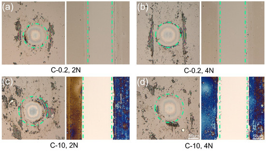
Figure 4.
Surface morphologies of ball scars and the wear tracks tested under different normal loads. (a) C−0.2 tested under 2 N, (b) C−0.2 tested under 4 N, (c) C−10 tested under 2 N, and (d) C−10 tested under 4 N.
From Figure 5a, it can be observed that the HPMC signal peaks appear at 259, 1156, 1338, 1463, and 1614 cm−1, while the mDLC−coated ball and GLC−coated disc exhibit D− and G−peaks at 521 and 977 cm−1, respectively. Figure 5b shows the Raman curve of the ball spot, which is similar to the mDLC peak shape. However, in the C−0.2 sample under 4 N, the intensity of the D−peak weakens, and no characteristic peaks of HPMC can be observed. This indicates that, under this operating condition, HPMC disassembled the molecular chain to form short chains induced by friction to form a new crystalline phase structure, thereby compensating for the surface defects after the abrasion of the mDLC−coated ball and improving the wear resistance of the ball surface. Then, in the C−10 sample under 4 N, the signal peaks are similar to the test results under the low concentration condition (C−0.2 under 4 N). Figure 5c shows the Raman curve of the wear track, which is similar to the GLC peak shape, indicating that HPMC is disassembled from the molecular chain induced by friction, as evidenced by the presence of D− and G−peaks near 1344 and 1545 cm cm−1.
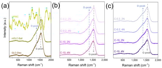
Figure 5.
Raman spectra of ball scars and the wear tracks were tested under different normal loads. (a) HPMC coating and tribo−couples (mDLC−coated steel ball against GLC−coated Si disc). (b) Ball scar. (c) Wear track.
3.3. Anti—Wear Mechanism
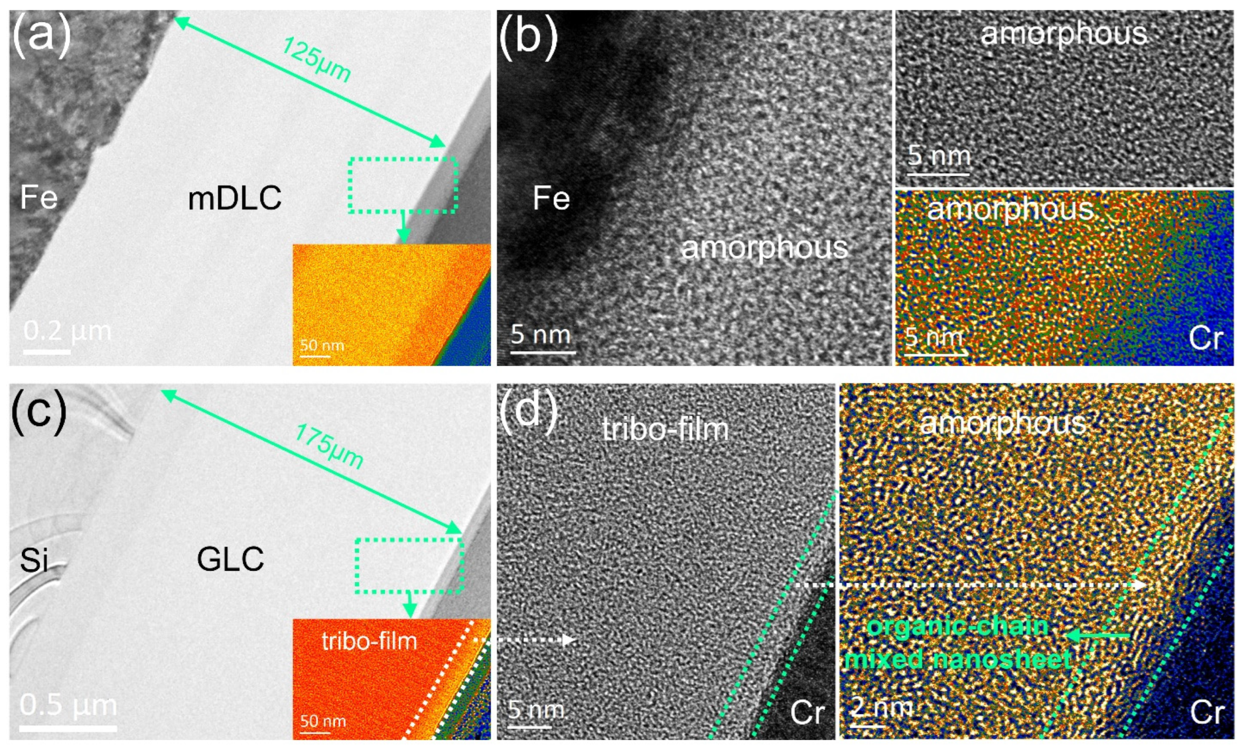
Because the elements in HPMC are composed of C, H, and O, these elements overlap with the elements on the contact surface (C and H) and the elements in the air (O, C, H, etc.). Therefore, it is difficult to distinguish the element composition of the interface structure by X−ray energy spectrum. Therefore, the interfacial structure is the representational emphasis. Figure 6 displays the nanostructures of the as−formed nanostructured tribofilm of the tribo−couples coated by C−0.2 HPMC and tested under 4 N. The HRTEM images show the clear interfacial nanostructures of the wear scar and the transferred substance. As shown in Figure 6a, we can divide the large film applied on the ball mark into three representative parts, including the topmost transferred substance, middle sublayer (mDLC), and underlying interlayer (Fe layer). On the contact surface of the ball, the tribofilm shows a defined amorphous phase (Figure 6b). Interestingly, on another counterbody (Figure 6c), we observe that a unique phenomenon appeared in the enlarged image of the top area. As shown in Figure 6d, under the protective Cr layer, the thin transferred substance contains a likely crystalline structure along the contact surface. When interacting with graphite−like carbon, a new structure may be formed with the participation of disassembled HPMC molecular chains induced by friction force. This is the tribofilm we mentioned, which consists of organic−chain mixed nanosheets originating from the disassembled HPMC coating and has a thickness of 3.5 nm. Notably, cellulose materials undergo a structural transform to form hydrocarbons and coke under high−temperature (below 350 °C) and high−pressure (atmospheric pressure) conditions [26]. During the sliding process, the frictional instantaneous temperature will rise to 300 °C [27,28]. It is reasonable to infer that these organic−chain mixed nanosheets are favorable for achieving an ultralow wear state.

Figure 6.
As−formed nanostructured tribofilm of the tribo−couples coated by C−0.2 HPMC tested under 4 N. (a,b) Ball scar. (c,d) Wear track. (a) HRTEM images show the whole cross−sectional morphology of the tribofilm. One representative of the nub is marked as a color area. (b) HRTEM images show the nanostructure of the mDLC film from (a). (c) HRTEM images show the whole cross−sectional morphology of the tribofilm. One representative of the nub is marked as a color area. (d) HRTEM images show the nanostructure of the PLC film from one representative region in (c).
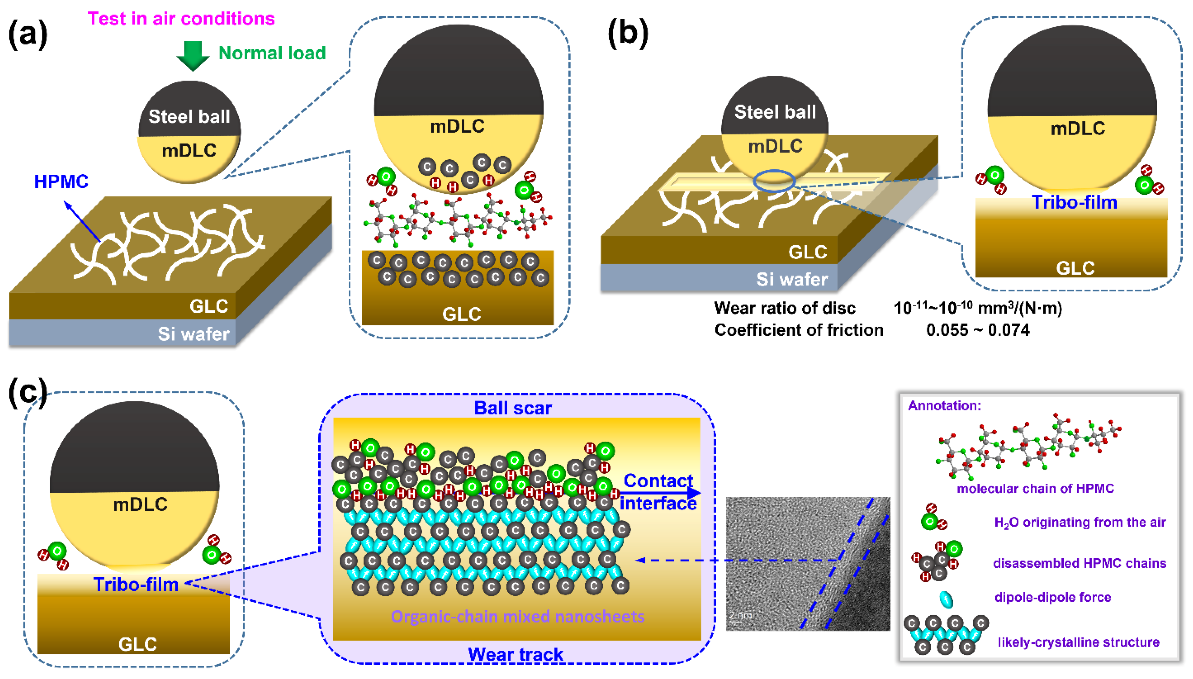
Figure 7 shows the wear−mechanism diagram of the HPMC coating under different loads. In the unloaded state, HPMC is distributed on the surface of the silicon wafer coated with GLC, as shown in Figure 7a. With the application of normal load, HPMC is damaged by the action of frictional force, and these damaged HPMCs can act as micro−protrusions, promoting the formation of a quasi−crystalline structure of nano−thin films with an ordered arrangement of the amorphous carbon phase. At the same time, some broken HPMC is transferred to the surface of the steel ball coated with mDLC, which helps to slow down or even repair the substrate surface damage induced by friction, as shown in Figure 7b. As the sliding continues, the orientation of graphite−like carbon induced by the decomposition of short chains of HPMC drives the formation of a transfer film containing organic−chain mixed nanosheets on the surfaces of both the upper and lower friction pairs, preventing direct contact between them. This achieves a transition from three−body wear (mDLC−coated ball, HPMC, and GLC−coated Si wafer) to two−body wear (tribo−film of mDLC−coated ball and tribo−film of GLC−coated Si wafer), resulting in ultra−low wear at the interface, as shown in Figure 7c.

Figure 7.
Wear mechanism diagram of HPMC coating under different loads. (a) Pre−loading process, (b) loading process, and (c) structure of tribofilm.
4. Conclusions
This study investigated the frictional behavior of HPMC under different load and concentration conditions through friction experiments, revealing the wear−resistance mechanism of HPMC. Therefore, it can be concluded that the type of friction pair significantly affects the frictional performance of HPMC in tribological tests. Moreover, the influence of load on the friction coefficient of HPMC is insignificant under the same solution concentration. Specifically, for the low−concentration samples (C−0.2), the wear ratio of HPMC under a 4 N load (1.01 × 10⁻¹¹ mm3·N−1·m−1) is noticeably lower than the wear ratio under a 2 N load (1.71 × 10⁻¹⁰ mm3·N−1·m−1). This suggests that the excellent wear resistance of HPMC can be primarily attributed to its film−forming ability and scratch self−healing capability. When subjected to frictional force, HPMC forms a transfer film at the contact interface, effectively protecting the silicon substrate. As the sliding continues, the orientation of the graphite−like carbon nanoflakes, formed by disassembled HPMC chains, drives the formation of a crystal−like nanostructure. The HPMC on the upper and lower friction surfaces forms a transfer film containing organic−chain mixed nanosheets, preventing direct contact between the friction surfaces and achieving two−body wear (mDLC−coated steel ball and GLC−coated Si wafer). HPMC boasts exceptional wear resistance and can uphold long−term wear stability even under high loads. Additionally, HPMC possesses environmentally friendly solid−lubricant properties, making it suitable for various environmental conditions.
Author Contributions
The manuscript was written through the contributions of all authors. H.P. and J.X. wrote the original draft. H.L. and W.W. searched literature resources. X.Y. and H.P. confirmed the final draft. X.Y., D.L. and B.Z. conceived the conceptualization. All authors have read and agreed to the published version of the manuscript.
Funding
This work is supported by the Open Fund Project of National United Engineering Laboratory for Advanced Bearing Tribology (202401), the Fundamental Research Funds for the Central Universities (JD2431), the Tribology Science Fund of the State Key Laboratory of Tribology in Advanced Equipment (SKLTKF23B02), and National Natural Science Foundation of China (52075284).
Data Availability Statement
Data available in a publicly accessible repository.
Acknowledgments
We very thank the technical support from Engineer Rong Wang in the Testing Center from State Key Laboratory of Tribology in Advanced Equipment, and Engineer Huihua Zhou in Beijing Electron Microscopy Center.
Conflicts of Interest
The authors declare no conflict of interest.
References
- Ali, M.K.A. Friction and Wear in Machine Design. Lubricants 2023, 11, 40. [Google Scholar] [CrossRef]
- Myshkin, N.K.; Goryacheva, I.G. Tribology: Trends in the half−century development. J. Frict. Wear 2016, 37, 513–516. [Google Scholar] [CrossRef]
- Yin, X.; Mu, L.; Jia, Z.; Pang, H.; Chai, C.; Liu, H.; Liang, C.; Zhang, B.; Liu, D. Nanostructure of Superlubricating Tribofilm Based on Friction−Induced a−C:H Films under Various Working Conditions: A Review of Solid Lubrication. Lubricants 2024, 12, 40. [Google Scholar] [CrossRef]
- Li, T.; Chen, C.; Brozena, A.H.; Zhu, J.Y.; Xu, L.; Driemeier, C.; Dai, J.; Rojas, O.J.; Isogai, A.; Wågberg, L.; et al. Developing fibrillated cellulose as a sustainable technological material. Nature 2021, 590, 47–56. [Google Scholar] [CrossRef] [PubMed]
- Eichhorn, S.J.; Etale, A.; Wang, J.; Berglund, L.A.; Li, Y.; Cai, Y.; Chen, C.; Cranston, E.D.; Johns, M.A.; Fang, Z.; et al. Current international research into cellulose as a functional nanomaterial for advanced applications. J. Mater. Sci. 2022, 57, 5697–5767. [Google Scholar] [CrossRef]
- Tanpichai, S.; Boonmahitthisud, A.; Soykeabkaew, N.; Ongthip, L. Review of the recent developments in all−cellulose nanocomposites: Properties and applications. Carbohydr. Polym. 2022, 286, 119192. [Google Scholar] [CrossRef] [PubMed]
- Lee, T.; Camp, C.P.; Kim, B.; Kim, M. Environmentally Friendly Methylcellulose Blend Binder for Hydrophobic Dust Control. ACS Appl. Polym. Mater. 2022, 4, 1512–1522. [Google Scholar] [CrossRef]
- Sheng, D.; Yu, H.; Li, H.; Zhou, J.; Zhang, H.; Wang, W. Friction Reduction Mechanism of Aqueous Hydroxyethyl Cellulose Solution Enhanced by Synergistic Effect of APTES. Tribol. Lett. 2021, 70, 7. [Google Scholar] [CrossRef]
- Grover, J.A. Methylcellulose (MC) and hydroxypropylmethylcellulose (HPMC). In Food hydrocolloids; CRC Press: Boca Raton, FL, USA, 2020; pp. 121–154. [Google Scholar]
- Matsuoka, T.; Kumagai, K.; Nonaka, H. Thermal extrusion of cellulose using hydroxypropyl methylcellulose. Cellulose 2022, 29, 2975–2983. [Google Scholar] [CrossRef]
- El Awad Azrak, S.M.; Costakis, W.J.; Moon, R.J.; Schueneman, G.T.; Youngblood, J.P. Continuous Processing of Cellulose Nanofibril Sheets Through Conventional Single−Screw Extrusion. ACS Appl. Polym. Mater. 2020, 2, 3365–3377. [Google Scholar] [CrossRef]
- Shi, S.-C.; Huang, T.-F. Raman study of HPMC biopolymer transfer layer formation under tribology test. Opt. Quantum Electron. 2016, 48, 532. [Google Scholar] [CrossRef]
- Shi, S.-C.; Huang, T.-F. Self−Healing Materials for Ecotribology. Materials 2017, 10, 91. [Google Scholar] [CrossRef] [PubMed]
- Hild, R.; Bergs, T.; Mattfeld, P.; Trauth, D.; Klocke, F.; Hoffmann, D.C.; Kruppe, N.C.; Brögelmann, T.; Bobzin, K. Analysis of wear phenomena during forward extrusion under dry friction conditions. Wear 2019, 426–427, 1362–1370. [Google Scholar] [CrossRef]
- Tian, J.; Qi, X.; Li, C.; Xian, G. Friction behaviors and wear mechanisms of multi−filler reinforced epoxy composites under dry and wet conditions: Effects of loads, sliding speeds, temperatures, water lubrication. Tribol. Int. 2023, 179, 108148. [Google Scholar] [CrossRef]
- Wang, L.; Zhou, J.; Duszczyk, J.; Katgerman, L. Friction in aluminium extrusion−Part 1: A review of friction testing techniques for aluminium extrusion. Tribol. Int. 2012, 56, 89–98. [Google Scholar] [CrossRef]
- Wang, L.; Zhang, Z.; Chen, H.; Wang, H.; Liu, Y.; Wang, J.; Wang, M. Friction behavior of diamond−like carbon coatings with different sp3 contents by atomistic−scale friction dynamics. Surf. Coat. Technol. 2023, 464, 129580. [Google Scholar] [CrossRef]
- Xu, J.; Deng, W.; Qi, W.; Chen, X.; Yu, X.; Wang, Y. Structural and environmental dependence of superlubricious properties in hydrogenated Graphite−Like carbon Films: Implications in solid state lubrication. Appl. Surf. Sci. 2023, 639, 158160. [Google Scholar] [CrossRef]
- Zia, A.W.; Birkett, M. Deposition of diamond−like carbon coatings: Conventional to non−conventional approaches for emerging markets. Ceram. Int. 2021, 47, 28075–28085. [Google Scholar] [CrossRef]
- Chen, X.; Li, J. Superlubricity of carbon nanostructures. Carbon 2020, 158, 1–23. [Google Scholar] [CrossRef]
- Martin, J.M.; Erdemir, A. Superlubricity: Friction’s vanishing act. Phys. Today 2018, 71, 40–46. [Google Scholar] [CrossRef]
- Zheng, Z.; Guo, Z.; Liu, W.; Luo, J. Low friction of superslippery and superlubricity: A review. Friction 2023, 11, 1121–1137. [Google Scholar] [CrossRef]
- Luo, J. Investigation on the origin of friction and superlubricity. Chin. Sci. Bull. 2020, 65, 2966–2978. [Google Scholar] [CrossRef]
- Hod, O.; Meyer, E.; Zheng, Q.; Urbakh, M. Structural superlubricity and ultralow friction across the length scales. Nature 2018, 563, 485–492. [Google Scholar] [CrossRef] [PubMed]
- Zhai, W.; Zhou, K. Nanomaterials in superlubricity. Adv. Funct. Mater. 2019, 29, 1806395. [Google Scholar] [CrossRef]
- Wang, D.-C.; Yu, H.-Y.; Qi, D.; Wu, Y.; Chen, L.; Li, Z. Confined Chemical Transitions for Direct Extraction of Conductive Cellulose Nanofibers with Graphitized Carbon Shell at Low Temperature and Pressure. J. Am. Chem. Soc. 2021, 143, 11620–11630. [Google Scholar] [CrossRef] [PubMed]
- Liu, Y.-C.; Wang, H.; Wang, W.-Z.; Hu, Y.-Z.; Zhu, D. Methods comparison in computation of temperature rise on frictional interfaces. Tribol. Int. 2002, 35, 549–560. [Google Scholar] [CrossRef]
- Huang, J.; Gao, C.; Chen, J.; Lin, X.; Ren, Z. Thermomechanical analysis of an elastoplastic rough body in sliding contact with flat surface and the effect of adjacent contact asperity. Adv. Mech. Eng. 2015, 7, 1–10. [Google Scholar] [CrossRef]


Disclaimer/Publisher’s Note: The statements, opinions and data contained in all publications are solely those of the individual author(s) and contributor(s) and not of MDPI and/or the editor(s). MDPI and/or the editor(s) disclaim responsibility for any injury to people or property resulting from any ideas, methods, instructions or products referred to in the content. |
© 2024 by the authors. Licensee MDPI, Basel, Switzerland. This article is an open access article distributed under the terms and conditions of the Creative Commons Attribution (CC BY) license (https://creativecommons.org/licenses/by/4.0/).