Ni-Cu Alloyed Austempered Ductile Iron Resistance to Multifactorial Wear


Abstract
:1. Introduction
- -
- Hard abrasives in the zone of the mating of machine components, which intensify abrasive processes;
- -
- Saline waters, which tend to induce electrochemical corrosion processes;
- -
- Dynamic excitations caused by start-up operations or sudden load changes which, in turn, can cause cracks in the microstructure, leading to material decohesion.
- -
- -
- -
- -
- -
- -
- Effect of the content of retained austenite on multifactorial wear, including impact–abrasion–corrosion;
- -
- Relationship between multifactorial wear and service hardness of the surface layer.
2. Materials and Methods
2.1. Research Method
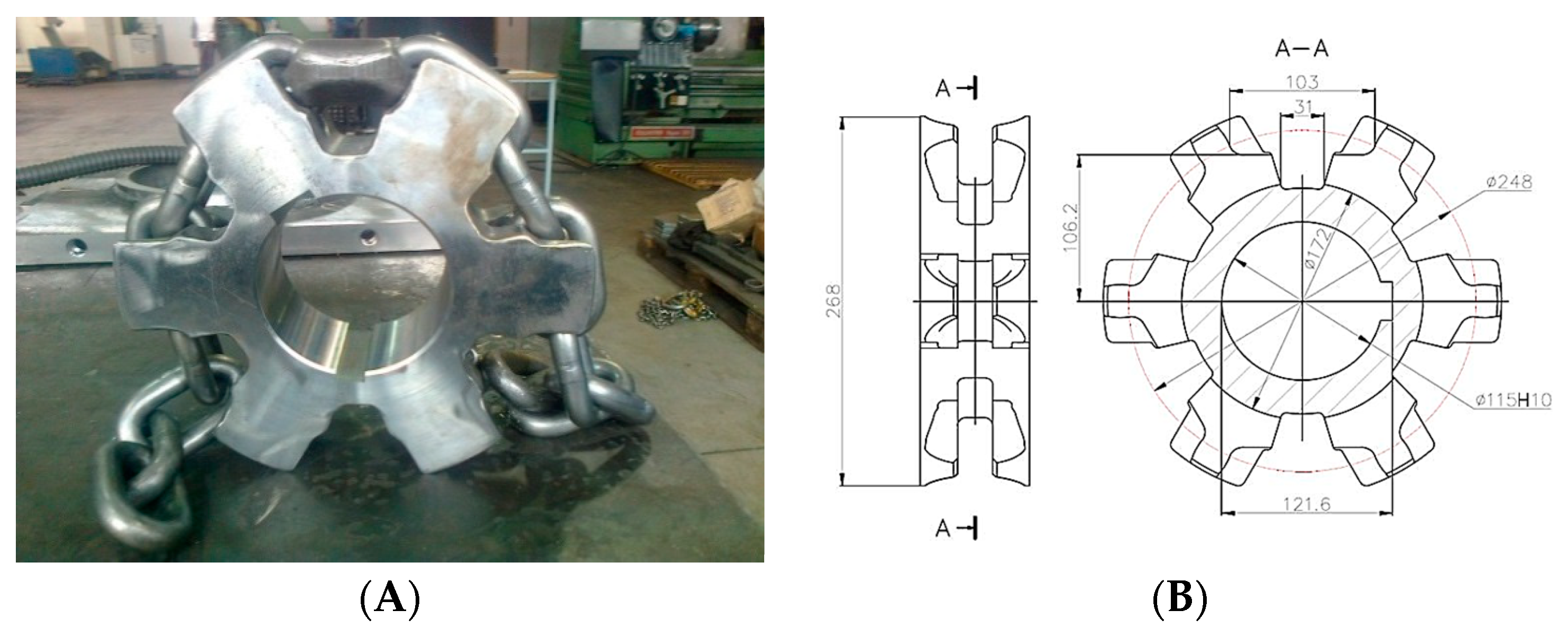
2.2. Object of Research
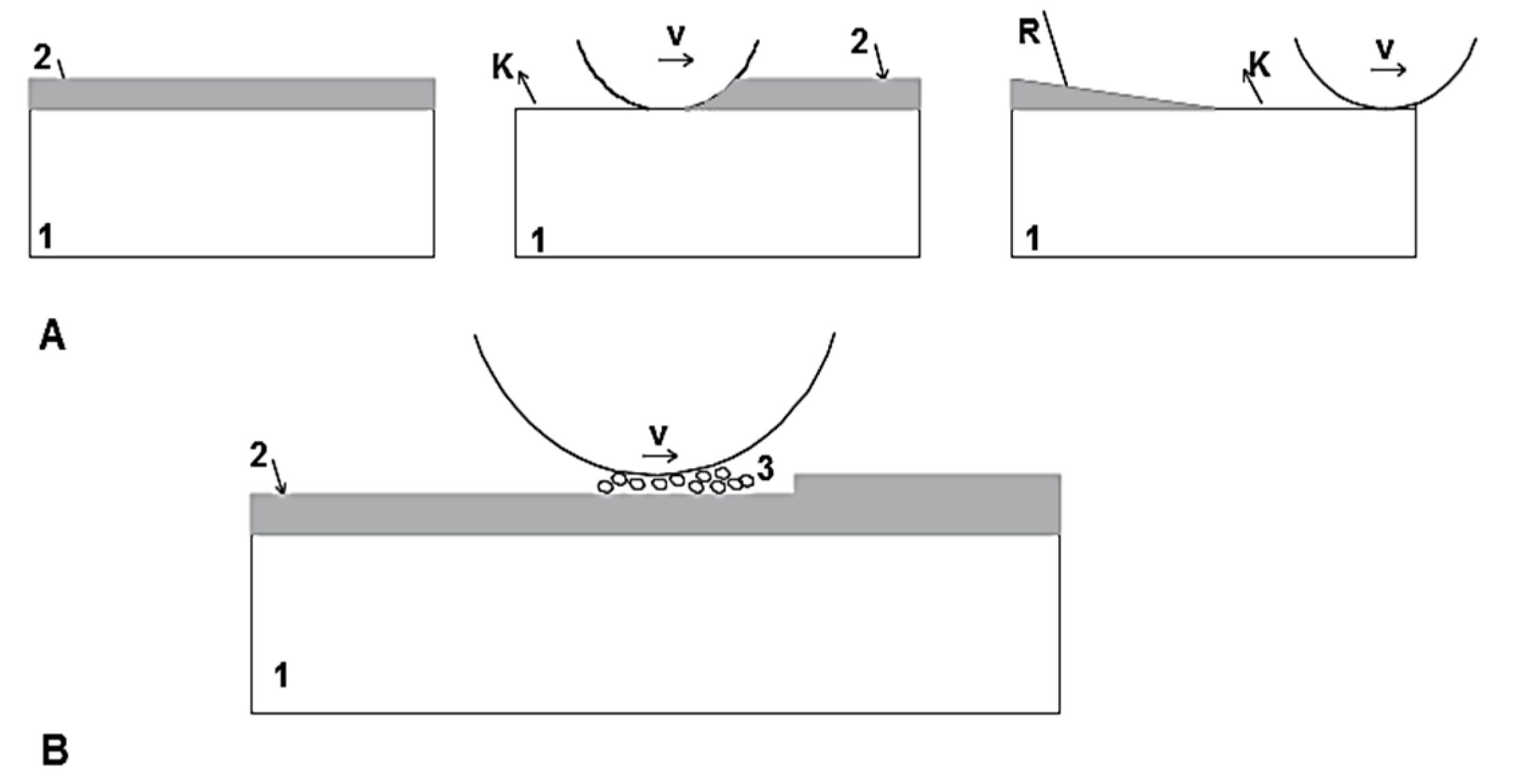
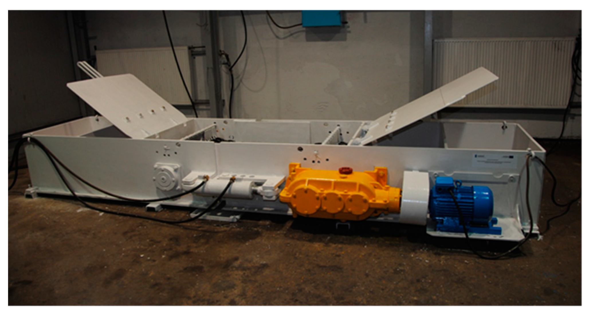
2.3. Wear Testing Station
- -
- Peripheral velocity of chain drums: 0.7 m/s;
- -
- Total test duration: 200 h (100 h for each direction of motor rotation);
- -
- Pressure on surface between drum seat and chain link: 48.9 MPa.
3. Results
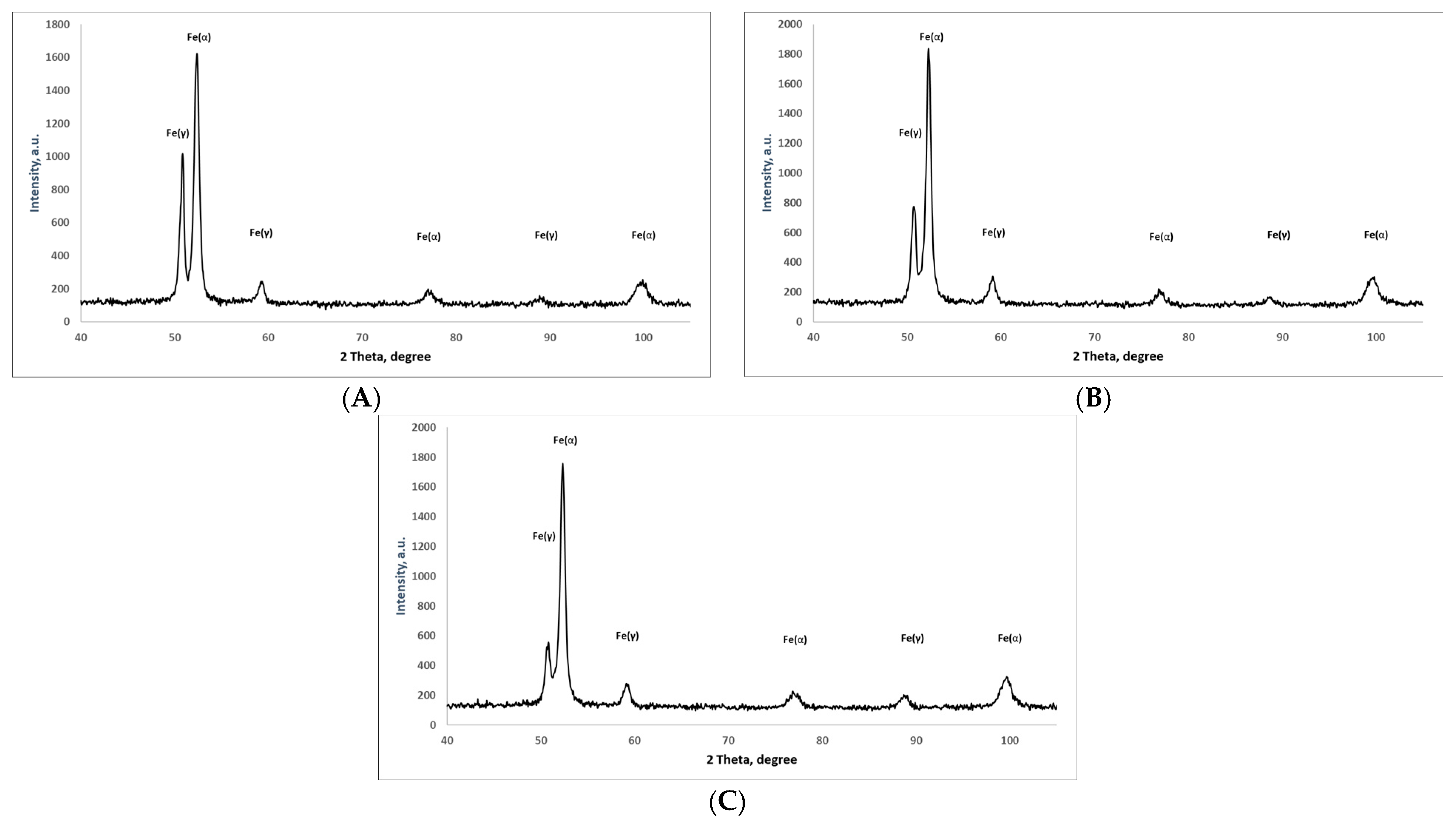
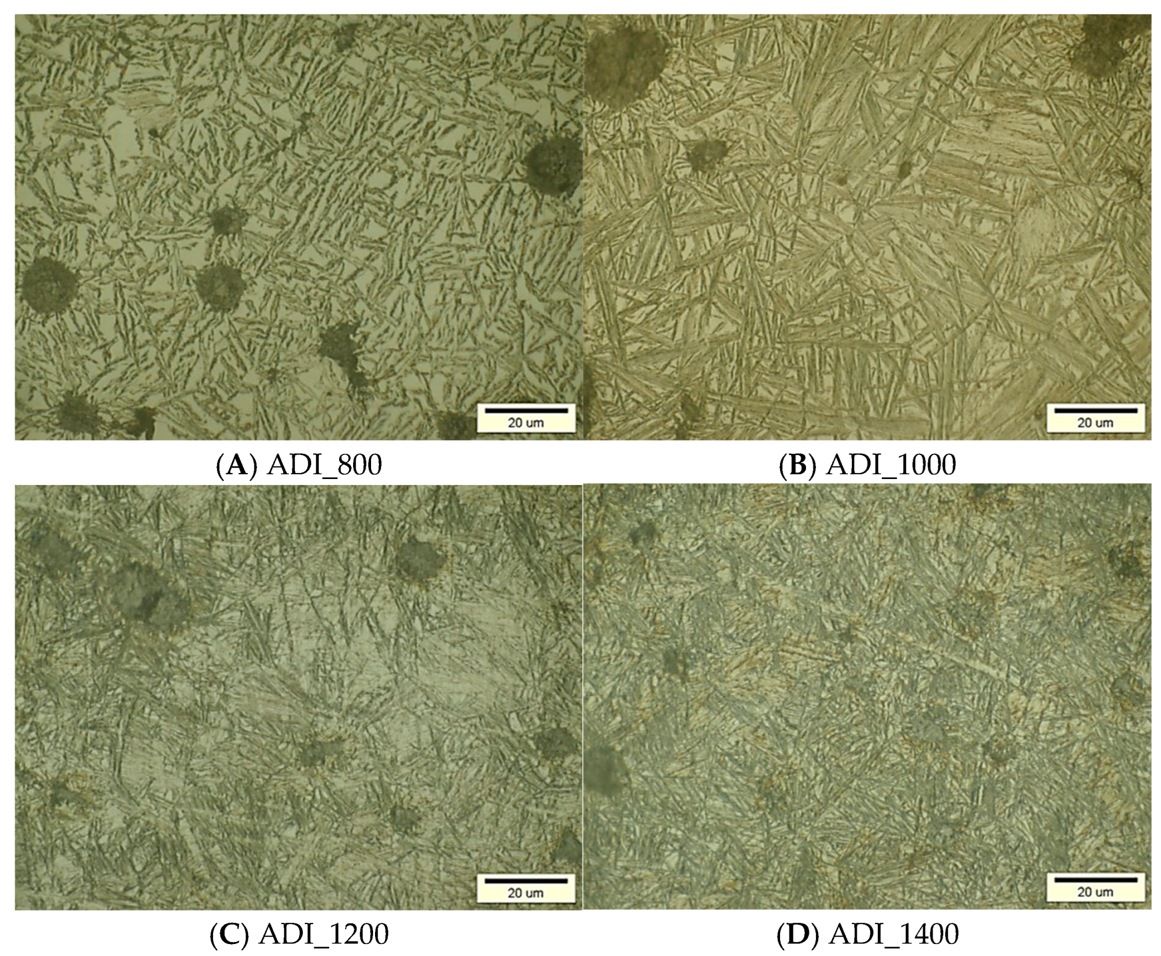
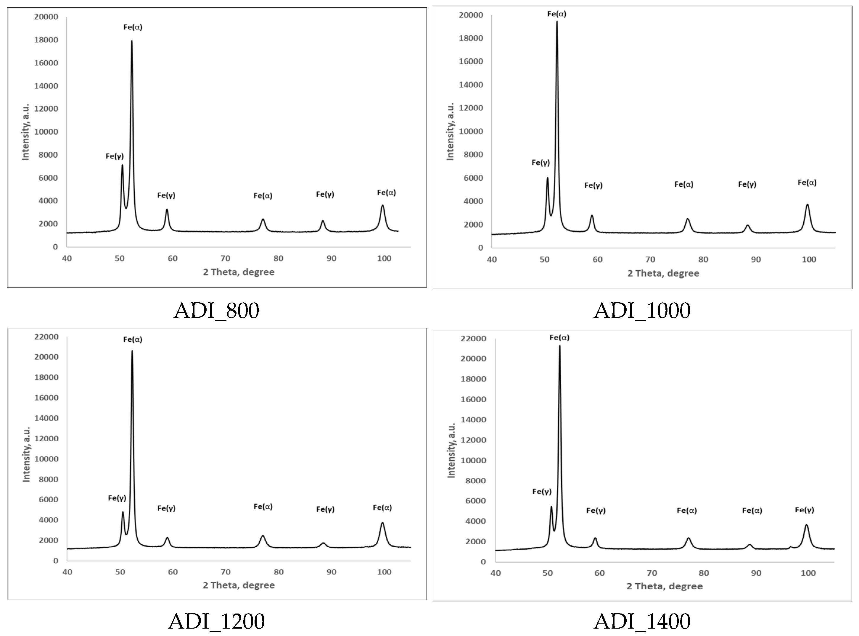
3.1. Identification of the Initial Structure of ADI and Its Corrosion Properties
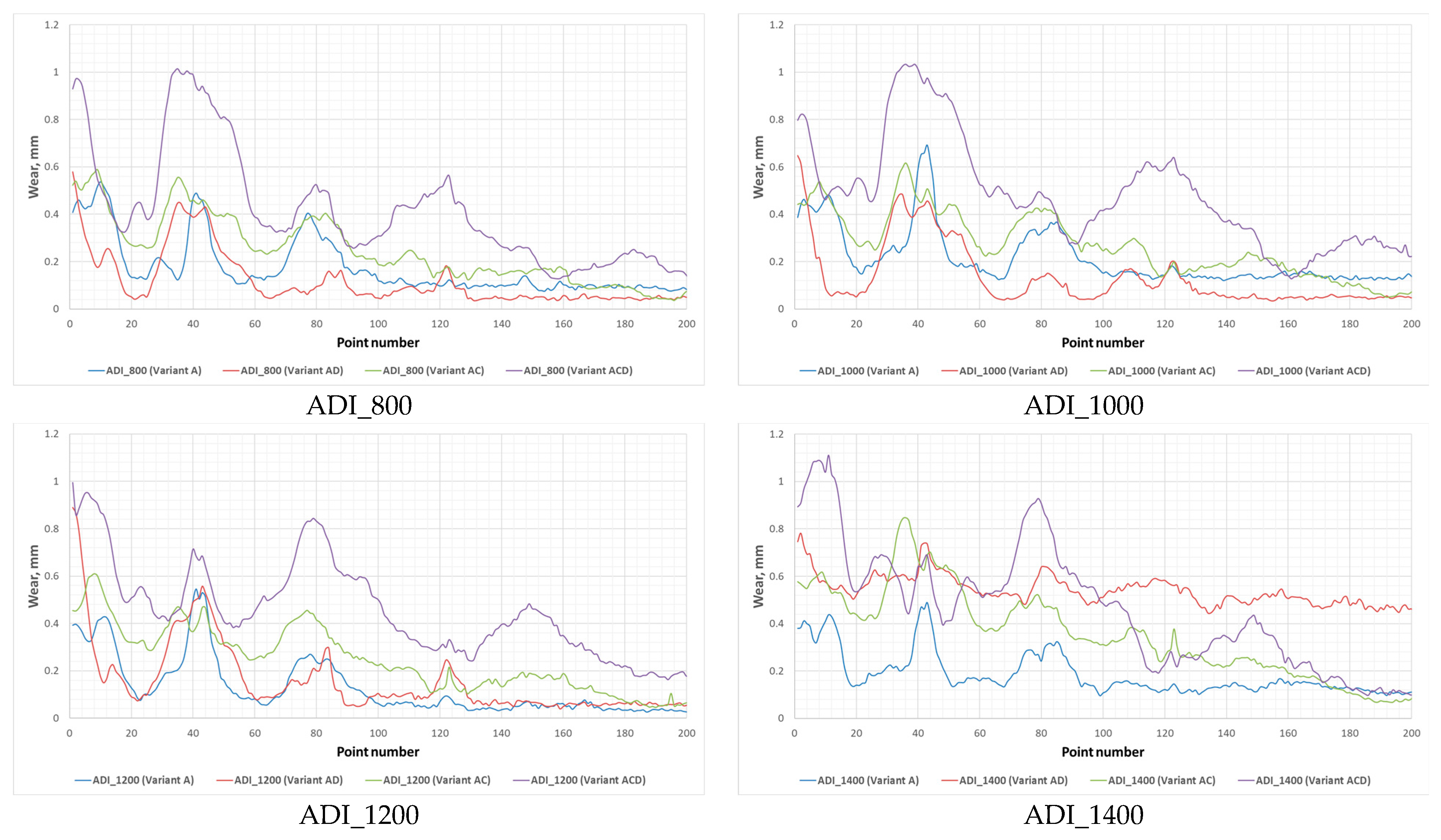
3.2. Wear Test Results
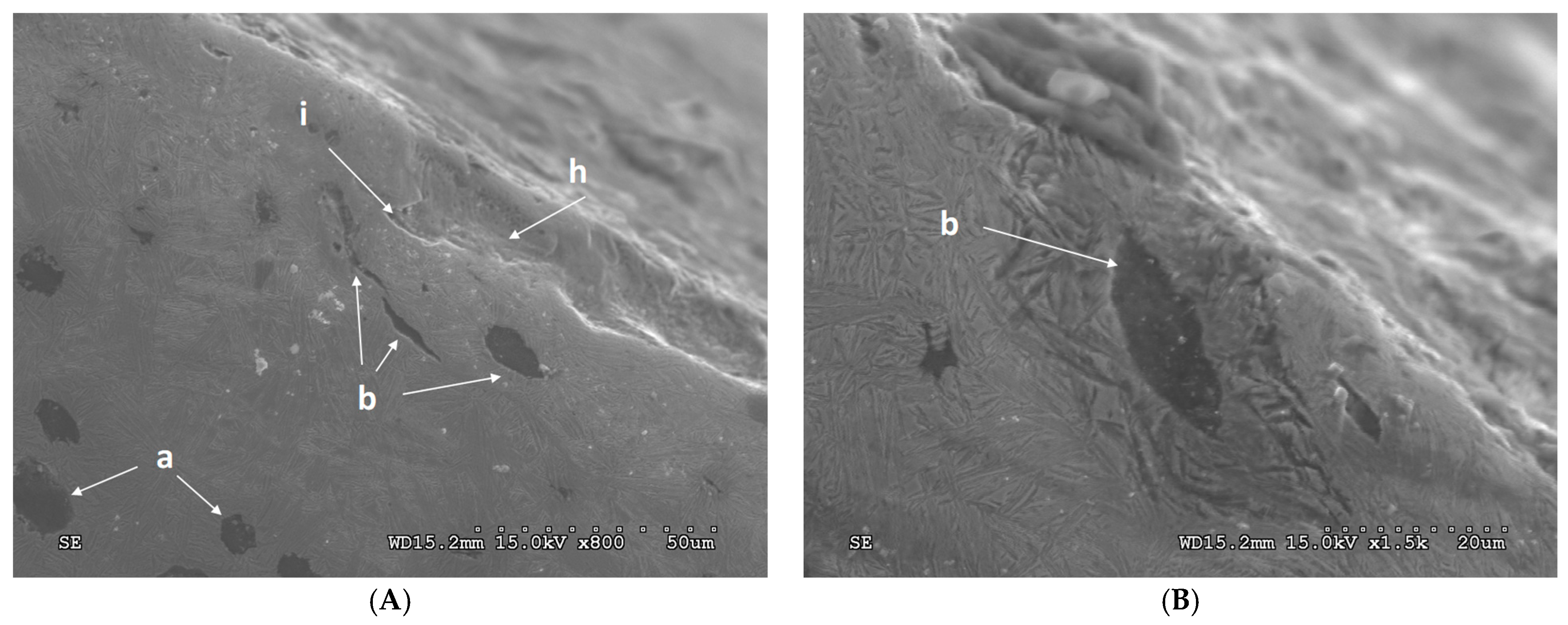
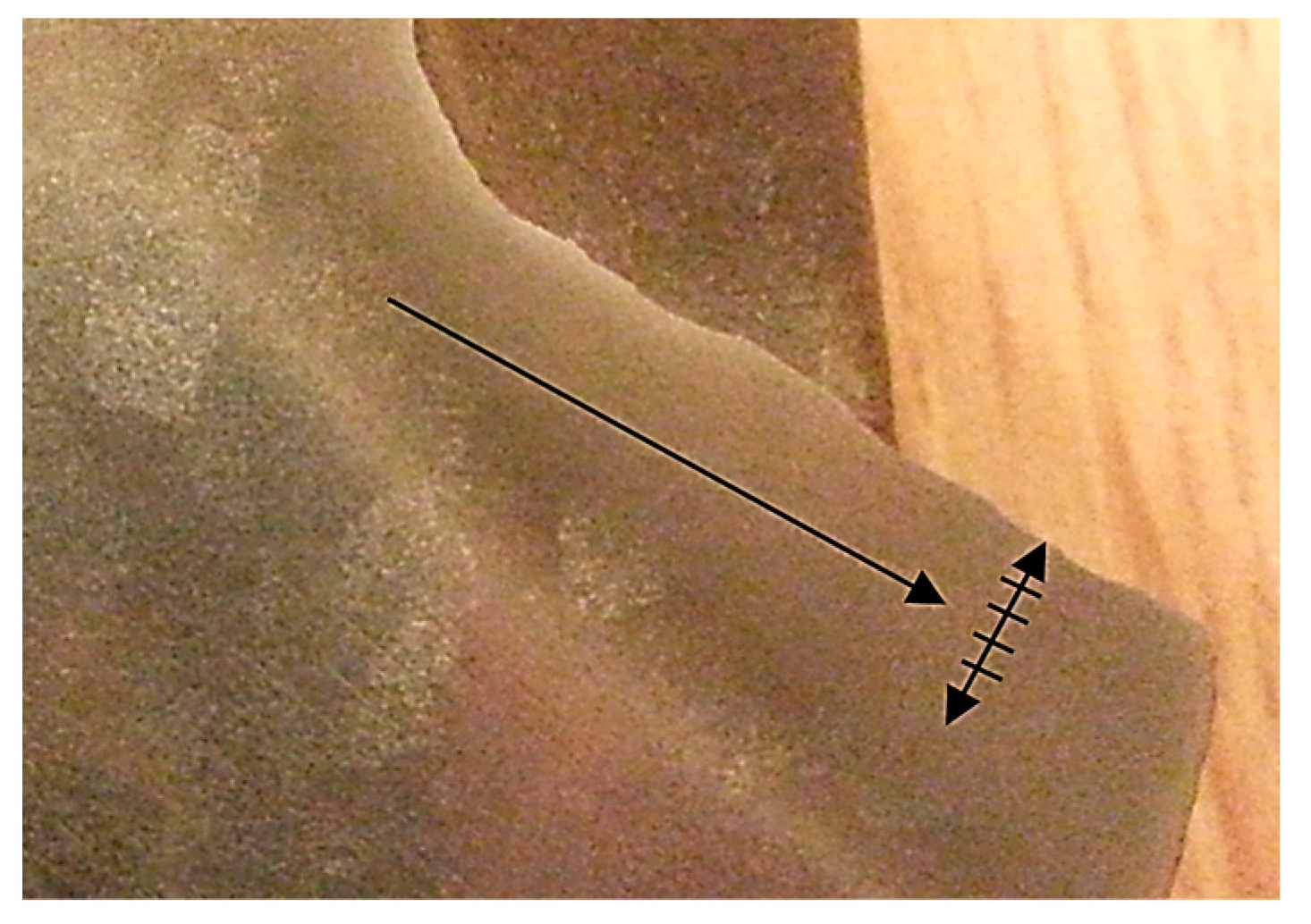
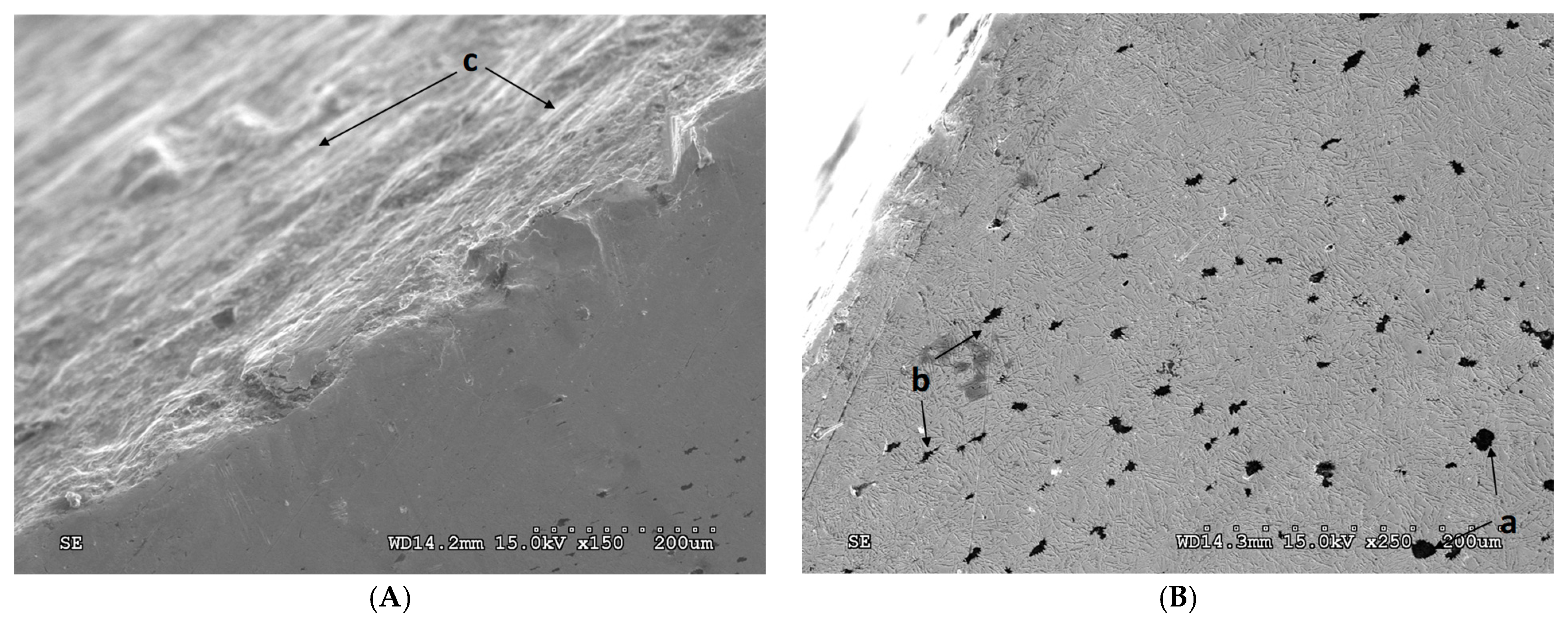
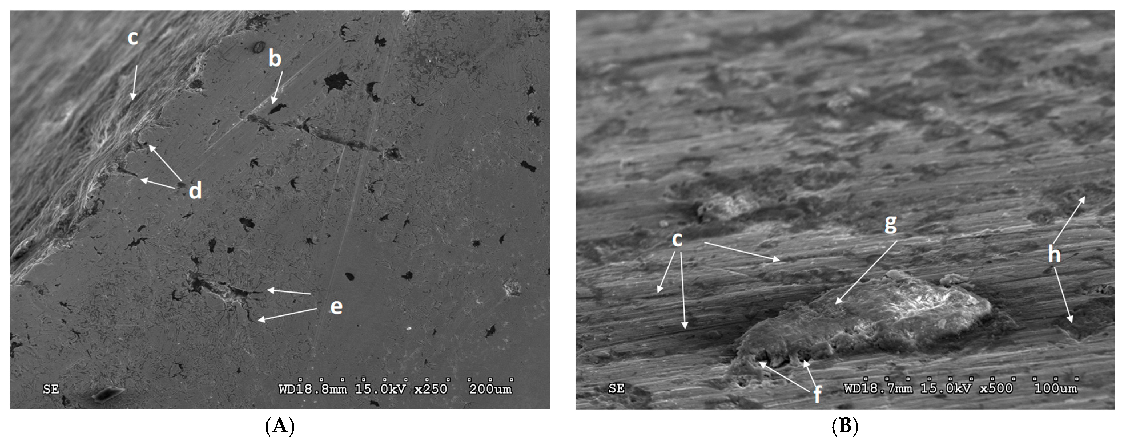
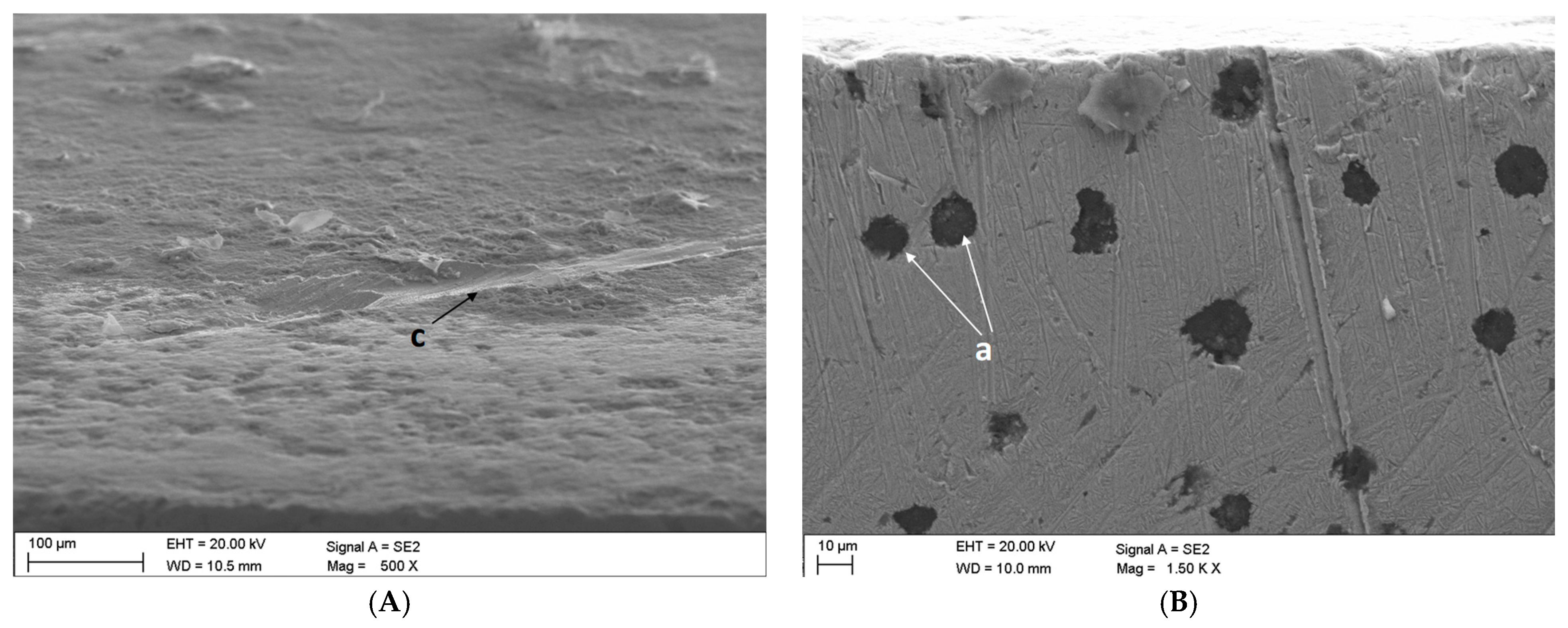
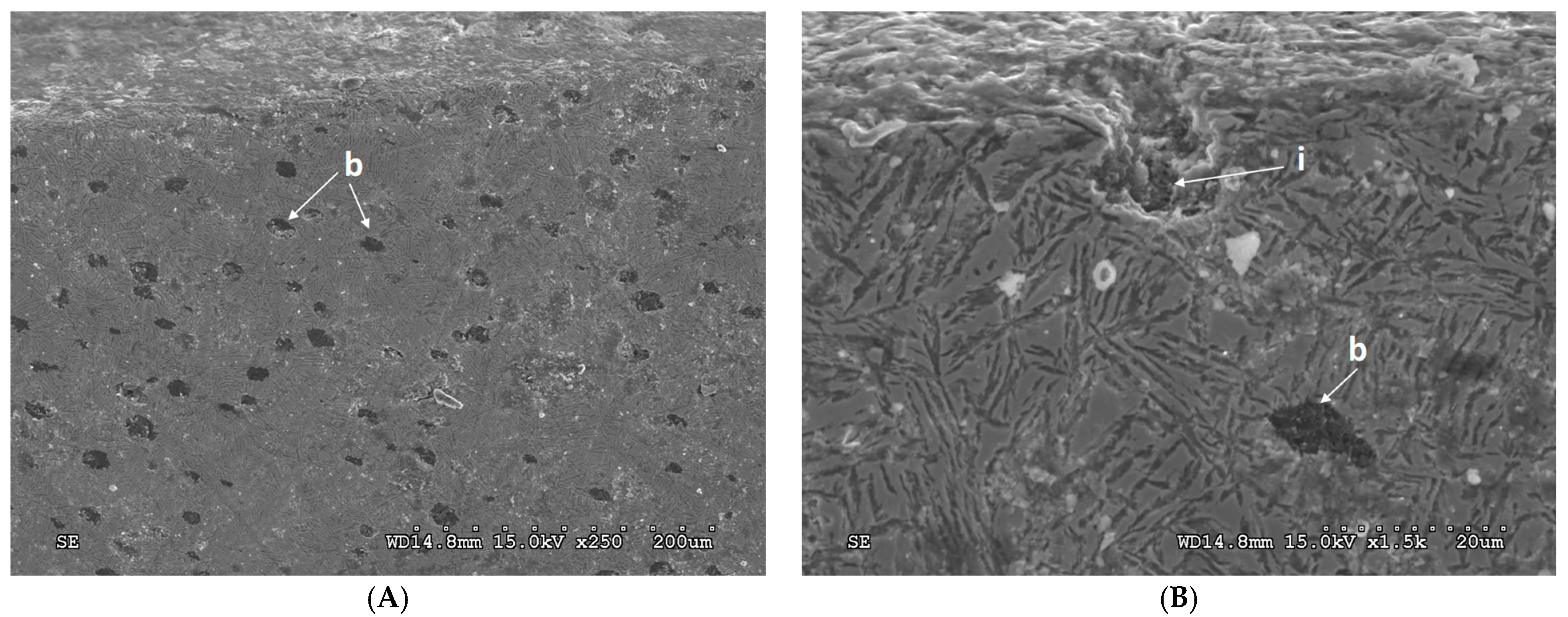
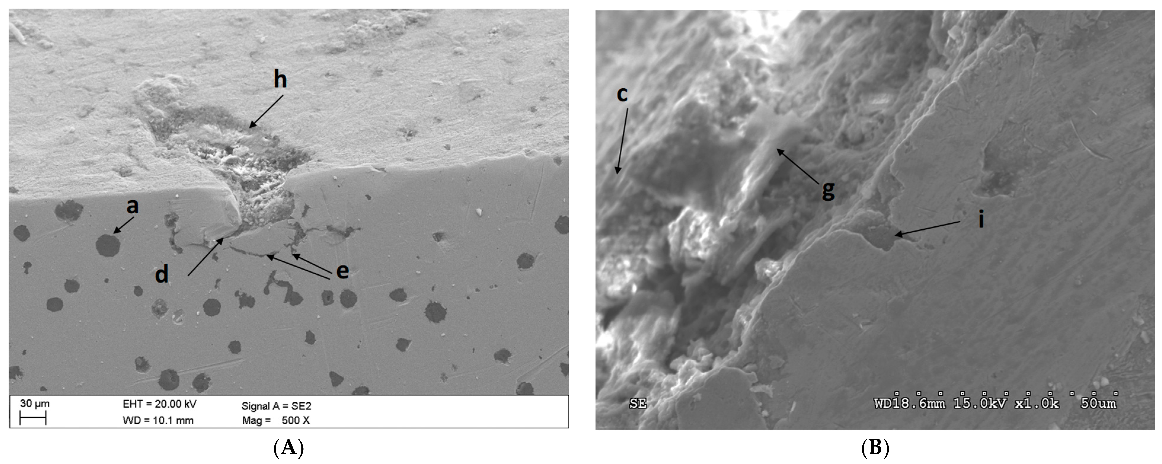
3.3. Damage Identification in the ADIs Subjected to Tests
4. Discussion
5. Conclusions
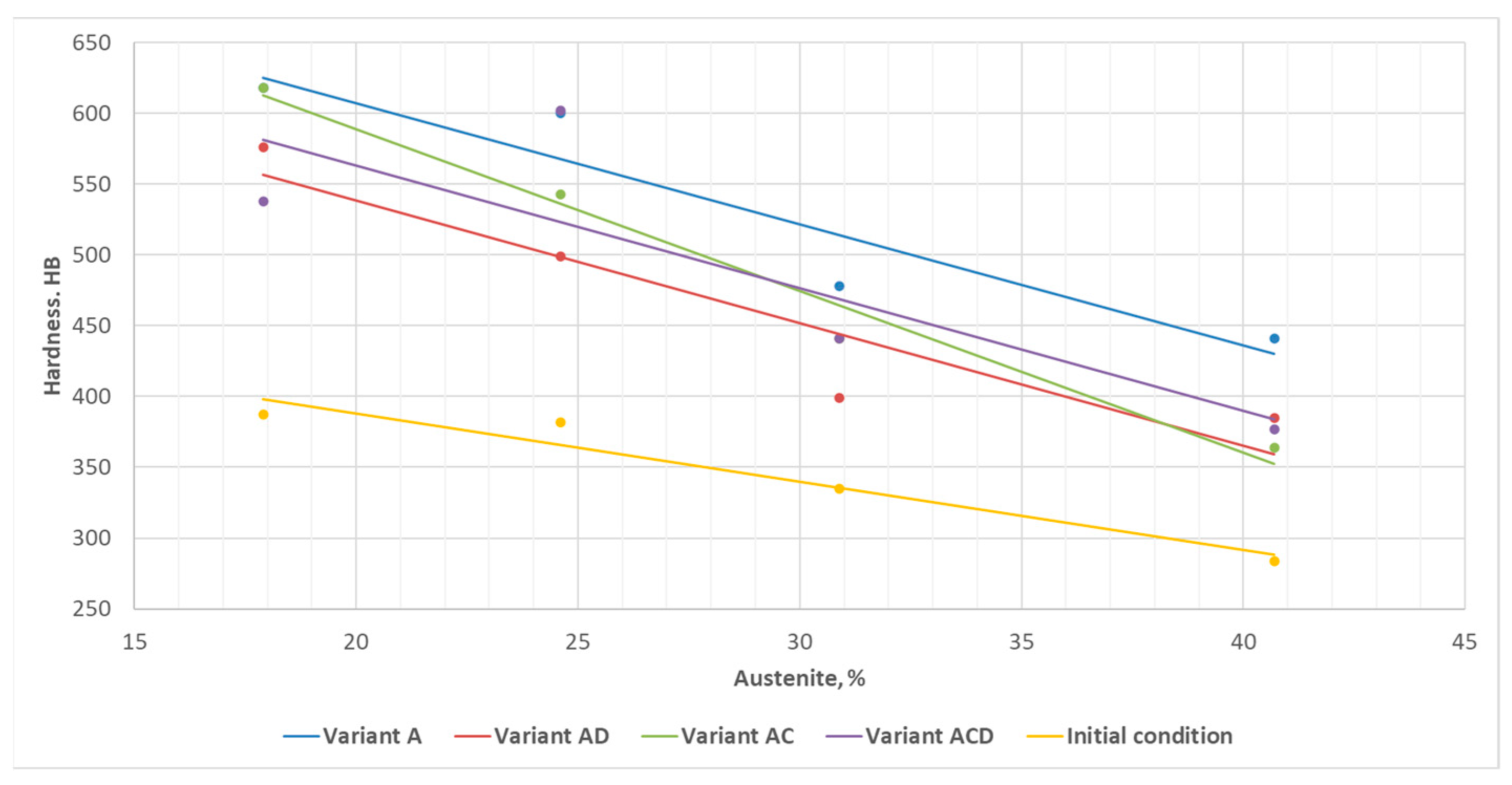
- Following a series of bench tests, making it possible to reproduce the processes of the wear of chain wheels made of Ni-Cu alloyed austempered ductile iron, one of the conclusions formulated in this paper, is that the combined effect of dynamic forces, corrosion, and quartz sand-based abrasives causes increased surface degradation in the cast iron grades subject to the studies compared with processes characterised by a reduced number of degradation factors (i.e., one- or two-factor wear processes).
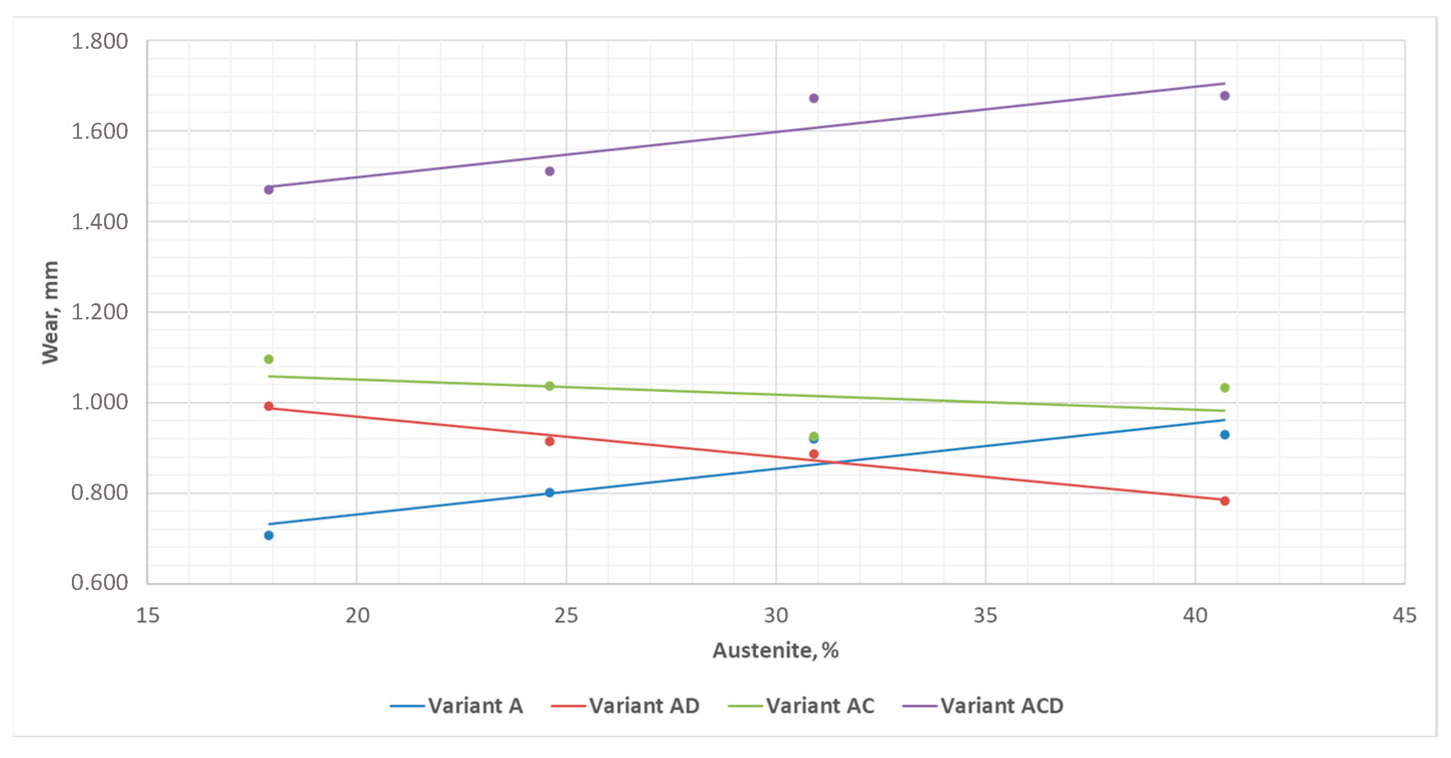
- The chain wheels made of ADI were found to have sustained the greatest damage under the impact–abrasion–corrosion (three-factor) wear scenario, while the wear was least advanced in the abrasion (one-factor) wear case. The two-factor wear was characterised by parameter values found to be intermediate between those obtained for the variants mentioned above, with a greater wear being observed for the tribocorrosion variant.
- The study demonstrated an increasing service hardness of the surface layer of chain wheels made of ADI following wear processes compared to the hardness of an unworn surface of ductile irons.
- The increase in the value of the surface layer hardness following wear tests depends on the combination of degradation factors, and the largest hardness increase has been established for the abrasive wear variant.
- The predominant forms of surface damage are as follows:
- -
- For abrasion wear—micro-scratching;
- -
- For impact–abrasion wear—micro-scratching and matrix cracking;
- -
- For tribocorrosion wear—micro-scratching and corrosion;
- -
- For impact–abrasion–corrosion wear—micro-scratching and matrix cracking.
Funding
Data Availability Statement
Conflicts of Interest
References
- Gilewski, R.; Kopyciński, D.; Guzik, E.; Szczęsny, A. Shaping the Microstructure of High-Aluminum Cast Iron in Terms of the Phenomenon of Spontaneous Decomposition Generated by the Presence of Aluminum Carbide. Materials 2021, 14, 5993. [Google Scholar] [CrossRef] [PubMed]
- Wieczorek, A.N. Designing machinery and equipment in accordance with the principle of sustainable development. Manag. Syst. Prod. Eng. 2015, 1, 28–34. [Google Scholar]
- Wang, H.; Li, Z. Safety management of coal mining process. In IOP Conference Series: Earth and Environmental Science; IOP Publishing: Jeju Island, Republic of Korea, 2020; p. 598. [Google Scholar]
- Szewerda, K.; Tokarczyk, J.; Wieczorek, A. Impact of Increased Travel Speed of a Transportation Set on the Dynamic Parameters of a Mine Suspended Monorail. Energies 2021, 14, 1528. [Google Scholar] [CrossRef]
- Angeles, E.; Kumral, M. Optimal Inspection and Preventive Maintenance Scheduling of Mining Equipment. J. Fail. Anal. Prev. 2020, 20, 1408–1416. [Google Scholar] [CrossRef]
- Liao, X.; Zheng, Z.; Liu, T.; Long, J.; Wang, S.; Zhang, H.; Zheng, K. Achieving high impact–abrasion–corrosion resistance of high–chromium wear–resistant steel via vanadium additions. J. Mater. Res. Technol. 2024, 29, 2425–2436. [Google Scholar] [CrossRef]
- Xia, R.; Li, B.; Wang, X.; Yang, Z.; Liu, L. Screening the Main Factors Affecting the Wear of the Scraper Conveyor Chute Using the Plackett–Burman Method. Hindawi Math. Probl. Eng. 2019, 2019, 1204091. [Google Scholar] [CrossRef]
- Kirchgaßner, M.; Badisch, E.; Franek, F. Behaviour of iron-based hardfacing alloys under abrasion and impact. Wear 2008, 265, 772–779. [Google Scholar] [CrossRef]
- Saha, G.; Valtonen, K.; Saastamoinen, A.; Peura, P.; Kuokkala, V.T. Impact-abrasive and abrasive wear behavior of low carbon steels with a range of hardness-toughness properties. Wear 2020, 450, 203263. [Google Scholar] [CrossRef]
- Widder, L.; Varga, M.; Adam, K.; Kuttner, A. Development of Impact Energy Distribution of Various Abrasives during Cyclic Impact/Abrasion Testing. Solid State Phenom. 2017, 267, 234–242. [Google Scholar] [CrossRef]
- Kennedy, D.M.; Helali, M.; Hashmi, M.S.J. Dynamic abrasion resistance of coatings applied to engineering materials. Surf. Coat. Technol. 1994, 68–69, 477–481. [Google Scholar] [CrossRef]
- Ratia, V.; Valtonen, K.; Kuokkala, V.-T. Impact-abrasion wear of wear-resistant steels at perpendicular and tilted angles. Proc. Inst. Mech. Eng. Part J J. Eng. Tribol. 2013, 227, 868–877. [Google Scholar] [CrossRef]
- Teeri, T.; Kuokkala, V.T.; Siitonen, P.; Kivikyto, P.; Liimatainen, J. Impact wear in mineral crushing. Proc. Est. Acad. Sci. Eng. 2006, 12, 408–418. [Google Scholar]
- Ratia, V.; Valtonen, K.; Kemppainen, A.; Kuokkala, V.-T. High Stress Abrasion and Impact-Abrasion Testing of wear Resistant Steels. Tribol. Online 2013, 8, 152–161. [Google Scholar] [CrossRef]
- Chintha, A.R.; Valtonen, K.; Kuokkala, V.T.; Kundu, S.; Peet, M.J.; Bhadeshia, H.K.D.H. Role of fracture toughness in impact-abrasion wear. Wear 2019, 428, 430–437. [Google Scholar] [CrossRef] [PubMed]
- Wieczorek, A.N. Operation-oriented studies on wear properties of surface-hardened alloy cast steels used in mining in the conditions of the combined action of dynamic forces and an abrasive material. Arch. Metall. Mater. 2017, 62, 2381–2389. [Google Scholar] [CrossRef]
- Sundström, A.; Rendón, J.; Olsson, M. Wear behaviour of some low alloyed steels under combined impact/abrasion contact conditions. Wear 2001, 250, 744–754. [Google Scholar] [CrossRef]
- Ratia, V.; Heino, V.; Valtonen, K.; Vippola, M.; Kemppainen, A.; Siitonen, P.; Kuokkala, V.T. Effect of abrasive properties on the high-stress three-body abrasion of steels and hard metals. Tribol.—Finn. J. Tribol. 2014, 32, 3–18. [Google Scholar]
- Wilson, R.D.; Hawk, J.A. Impeller wear impact-abrasive wear test. Wear 1999, 225, 1248–1257. [Google Scholar] [CrossRef]
- Mindivan, F.; Yildirim, M.P.; Bayindir, F.; Mindivan, H. Corrosion and Tribocorrosion Behavior of Cast and Machine Milled Co-Cr Alloys for Biomedical Applications. Acta Phys. Pol. 2016, 129, 701–704. [Google Scholar] [CrossRef]
- Mischler, S. Triboelectrochemical techniques and interpretation methods in tribocorrosion: A comparative evaluation. Tribol. Int. 2008, 41, 573–583. [Google Scholar] [CrossRef]
- Watson, S.W.; Friedersdorf, F.J.; Madsen, B.W.; Cramer, S.D. Methods of measuring wear-corrosion synergism. Wear 1995, 181–183, 476–484. [Google Scholar]
- Jemmely, P.; Mischler, S.; Landolt, D. Electrochemical modeling of passivation phenomena in tribocorrosion. Wear 2000, 237, 63–76. [Google Scholar] [CrossRef]
- Cao, S.; Mischler, S. Modeling tribocorrosion of passive metals—A review. Curr. Opin. Solid State Mater. Sci. 2018, 22, 127–141. [Google Scholar] [CrossRef]
- Ponthiaux, P.; Wenger, F.; Celis, J.P. Tribocorrosion: Material behaviour under combined conditions of corrosion and mechanical loading. In Corrosion Resistance; Books on Demand GmbH: Norderstedt, Germany, 2012. [Google Scholar]
- Bailey, R.; Sun, Y. Corrosive-Wear Performance of Grade 316 Stainless Steel Sliding Against Grade 316 Stainless Steel in NaCl Solution. J. Mater. Eng. Perform. 2023, 1–13. [Google Scholar] [CrossRef]
- Dalmau, A.; Richard, C.; Igual-Muñoz, A. Degradation mechanisms in martensitic stainless steels: Wear, corrosion and tribocorrosion appraisal. Tribol. Int. 2018, 121, 167–179. [Google Scholar] [CrossRef]
- Ghanbarzadeh, A.; Salehi, F.M.; Bryant, M.; Neville, A. A New Asperity-Scale Mechanistic Model of Tribocorrosive Wear: Synergistic Effects of Mechanical Wear and Corrosion. J. Tribol. 2019, 141, 021601. [Google Scholar] [CrossRef]
- Fallahnezhad, K.; Feyzi, M.; Ghadirinejad, K.; Hashemi, R.; Taylor, M. Finite element-based simulation of tribocorrosion at the head-neck junction of hip implants. Tribol. Int. 2022, 165, 107284. [Google Scholar] [CrossRef]
- Jiang, J.; Islam, M.A.; Xie, Y.; Stack, M.M. Some Thoughts on Modeling Abrasion-Corrosion: Wear by Hard Particles in Corrosive Environments. J. Bio-Tribo-Corros. 2024, 10, 12. [Google Scholar] [CrossRef]
- Stachowiak, A.; Tyczewski, P.; Zwierzycki, W. The application of wear maps for analyzing the results of research into tribocorrosion. Wear 2016, 352–353, 146–154. [Google Scholar] [CrossRef]
- Munoz, A.I.; Espallargas, N.; Mischler, S. Tribocorrosion; Springer: Berlin/Heidelberg, Germany, 2020. [Google Scholar]
- Wang, X.Y.; Li, D.Y. Investigation of the synergism of wear and corrosion using an electrochemical scratch technique. Tribol. Lett. 2001, 11, 117–120. [Google Scholar] [CrossRef]
- Bhadeshia, H.K.D.H. Bainite in Steels; The Institute of Materials: Cambridge, UK, 2001. [Google Scholar]
- Caballero, F.G.; Bhadeshia, H.K.D.H. Very Strong Bainite. Curr. Opinoin Solid State Mater. Sci. 2004, 8, 251–257. [Google Scholar] [CrossRef]
- Hayrynen, K.L.; Keough, J.R.; Pioszak, G.L. Designing with Austempered Ductile Iron. AFS Trans. 2010, 129, 1–15. [Google Scholar]
- Myszka, D. Cast Iron–Based Alloys. In High-Performance Ferrous Alloys; Rana, R., Ed.; Springer: Berlin/Heidelberg, Germany, 2020; pp. 153–210. [Google Scholar]
- Massone, J.; Boeri, R.; Sikora, J. Production of ADI by hot shake out—Microstructure and mechanical properties. Int. J. Cast Met. Res. 1999, 11, 419–424. [Google Scholar] [CrossRef]
- Guzik, E. ADI cast iron and its variants as modern structural alloys. In Engineering Forum “Development of ADI Cast Iron Technology in Poland”; Foundry Research Institute in Cracow: Cracow, Poland, 2009; pp. 37–49. [Google Scholar]
- Yang, J.; Putatunda, S.K. Effect of microstructure on abrasion wear behavior of austempered ductile cast iron (ADI) processed by a novel two-step austempering process. Mater. Sci. Eng. A 2005, 406, 217–228. [Google Scholar] [CrossRef]
- Yang, J.; Putatunda, S.K. Influence of a novel two-step austempering process on the strain-hardening behaviour of austempered ductile cast iron (ADI). Mater. Sci. Eng. A 2004, 382, 265–279. [Google Scholar] [CrossRef]
- Azevedo, C.R.F.; Garboggini, A.A.; Tschipitschin, A.P. Effect of austenite grain refinement on morphology of product of bainitic reaction in austempered ductile iron. Mater. Sci. Technol. 1993, 9, 705–710. [Google Scholar] [CrossRef]
- Ghasemi, R.; Hassan, I.; Ghorbani, A.; Dioszegi, A. Austempered compacted graphite iron—Influence of austempering temperature and time on microstructural and mechanical properties. Mater. Sci. Eng. A 2019, 767, 138434. [Google Scholar] [CrossRef]
- Bayati, H.; Elliot, R. The concept of an austempered heat treatment processing window. Int. J. Cast Met. Res. 1999, 11, 413–417. [Google Scholar] [CrossRef]
- Colin-García, E.; Cruz-Ramírez, A.; Romero-Serrano, J.A.; Sánchez-Alvarado, R.G.; Gutiérrez-Pérez, V.H.; Reyes-Castellanos, G. Nodule count effect on microstructure and mechanical properties of hypo-eutectic adi alloyed with nickel. J. Min. Metall. Sect. B-Metall. 2021, 57, 115–124. [Google Scholar] [CrossRef]
- Myszka, D.; Cybula, L.; Wieczorek, A.N. Influence of heat treatment conditions on microstructure and mechanical properties of austempered ductile iron after dynamic deformation test. Arch. Metall. Mater. 2014, 59, 1181–1189. [Google Scholar] [CrossRef]
- Wieczorek, A.N. Influence of Shot Peening on Abrasion Wear in Real Conditions of Ni-Cu-Ausferritic Ductile Iron. Arch. Metall. Mater. 2016, 61, 1985–1990. [Google Scholar] [CrossRef]
- Zammit, A.; Abela, S.; Wagner, L.; Mhaede, M.; Grech, M. Tribological behavior of shot peened Cu-Ni austempered ductile iron. Wear 2013, 302, 829–836. [Google Scholar] [CrossRef]
- Zammit, A.; Bonnici, M.; Mhaede, M.; Wan, R.; Wagner, L. Shot peening of austempered ductile iron gears. Surf. Eng. 2017, 33, 679–686. [Google Scholar] [CrossRef]
- Zammit, A.; Mhaede, M.; Grech, M.; Abela, S.; Wagner, L. Influence of shot peening on the fatigue life of Cu-Ni austempered ductile iron. Mater. Sci. Eng. A 2012, 545, 78–85. [Google Scholar] [CrossRef]
- Sevillano, J.G.; Aldazabal, J. Ductilization of nanocrystalline materials for structural applications. Sci. Mater. 2004, 51, 795–800. [Google Scholar] [CrossRef]
- Rementeria, R.; Aranda, M.M.; Garcia-Mateo, C.; Caballero, F.G. Improving wear resistance of steels through nanocrystalline structures obtained by bainitic transformation. Mater. Sci. Technol. 2016, 32, 308–312. [Google Scholar] [CrossRef]
- Myszka, D.; Skołek, E.; Wieczorek, A. Manufacture of toothed elements in nanoausferritic ductile iron. Arch. Metall. Mater. 2014, 59, 1227–1231. [Google Scholar] [CrossRef]
- Myszka, D.; Wasiluk, K.; Skołek, E.; Swiatnicki, W. Nanoausferritic matrix of ductile iron. Mater. Sci. Technol. 2015, 31, 829–834. [Google Scholar] [CrossRef]
- Panneerselvam, S. Development of Nanostructured Austempered Ductile Cast Iron. Ph.D. Thesis, Wayne State University, Detroit, MI, USA, 2017; p. 1856. Available online: https://digitalcommons.wayne.edu/oa_dissertations/1856 (accessed on 20 February 2023).
- Myszka, D. Technological aspects of deformation-induced transformation in austempered ductile iron. In Scientific Works of the Warsaw University of Technology. Mechanics; Warsaw University of Technology: Warsaw, Poland, 2014. [Google Scholar]
- Soliman, M.; Palkowski, H.; Nofal, A. Multiphase ausformed austempered ductile iron. Arch. Metall. Mater. 2017, 62, 1493–1498. [Google Scholar] [CrossRef]
- Myszka, D. Austenite-martensite trasformation in austempered ductile iron, Arch. Metall. Mater. 2007, 52, 475–480. [Google Scholar]
- Nili-Ahmadabadi, M.; Shirazi, H. Austempered ductile cast iron: Bainitic transformation. In Encyclopedia of Iron, Steel, and Their Alloys; CRC Press: Boca Raton, FL, USA, 2015; pp. 217–230. [Google Scholar]
- Ritha Kumari, U.; Prasad Rao, P. Study of wear behaviour of austempered ductile iron. J. Mater. Sci. 2009, 44, 1082–1093. [Google Scholar] [CrossRef]
- Suchocki, C.; Myszka, D.; Wasiluk, K. Transformation Kinetics of Austempered Ductile Iron: Dilatometric Experiments and Model Parameter Evaluation. Arch. Metall. Mater. 2019, 64, 1661–1666. [Google Scholar] [CrossRef]
- Hayrynen, K.L.; Keough, J.R. Wear Properties of Austempered Ductile Cast Irons. AFS Trans. 2005, 187, 1–10. [Google Scholar]
- Sellamuthu, P.; Samuel, D.G.; Dinakaran, D.; Premkumar, V.P.; Li, Z.; Seetharaman, S. Austempered ductile iron (ADI): Influence of austempering temperature on microstructure, mechanical and wear properties and energy consumption. Metals 2018, 8, 53. [Google Scholar] [CrossRef]
- Ahmadabadi, M.N.; Ghasemi, H.M.; Osia, M. Effects of successive austempering on the tribological behavior of ductile cast iron. Wear 1999, 231, 293–300. [Google Scholar] [CrossRef]
- Chang, L.C.; Hsui, I.C.; Chen, L.H.; Lui, T.S. Effects of heat treatment on the erosion behavior of austempered ductile irons. Wear 2006, 260, 783–793. [Google Scholar] [CrossRef]
- Myszka, D.; Wieczorek, A.N. Effect of phenomena accompanying wear in dry corundum abrasive on the properties and microstructure of austempered ductile iron with different chemical composition. Arch. Metall. Mater. 2015, 60, 483–490. [Google Scholar] [CrossRef]
- Zhang, N.; Zhang, J.; Lu, L.; Zhang, M.; Zeng, D.; Song, Q. Wear and friction behavior of austempered ductile iron as railway wheel material. Mater. Des. 2016, 89, 815–822. [Google Scholar] [CrossRef]
- Wieczorek, A.N. The role of operational factors in shaping of wear properties of alloyed Austempered Ductile Iron. Part I. Experimental studies abrasive wear of Austempered Ductile Iron (ADI) in the presence of loose quartz abrasive. Arch. Metall. Mater. 2014, 59, 1665–1674. [Google Scholar] [CrossRef]
- Wieczorek, A.N. The role of operational factors in shaping of wear properties of alloyed Austempered Ductile Iron. Part II. An assessment of the cumulative effect of abrasives processes and the dynamic activity on the wear property of Ausferritic Ductile Iron. Arch. Metall. Mater. 2014, 59, 1675–1683. [Google Scholar] [CrossRef]
- Navarro-Mesa, C.H.; Gómez-Botero, M.; Montoya-Mejía, M.; Ríos-Diez, O.; Aristizábal-Sierra, R. Wear resistance of austempered grey iron under dry and wet conditions. J. Mater. Res. Technol. 2022, 21, 4174–4183. [Google Scholar] [CrossRef]
- Stachowiak, A.; Wieczorek, A.N. Comparative tribocorrosion tests of 30CrMo12 cast steel and ADI spheroidal cast iron. Tribol. Int. 2021, 155, 106763. [Google Scholar] [CrossRef]
- PN-EN 1564:2012; Founding—Ausferritic Spheroidal Graphite Cast Irons. National Standards Authority of Ireland: Dublin, Ireland, 2012.
- Wieczorek, A.N.; Polis, W. Operation-oriented method for testing the abrasive wear of mining chain wheels in the conditions of the combined action of destructive factors. Manag. Syst. Prod. Eng. 2015, 19, 175–178. [Google Scholar]
- Putatunda, S.K.; Bingi, G.A. Influence of step-down austempering process on the fracture toughness of austempered ductile iron. J. Mater. Sci. Eng. Adv. Technol. 2005, 5, 39–70. [Google Scholar]
- Ravishankar, K.S.; Rajendra Udupa, K.; Prasad Rao, P. Development of Austempered Ductile Iron for High Tensile and Fracture toughness by Two Step Austempering Process. In Proceedings of the 68th WFC—World Foundry Congress, Chennai, India, 7–11 February 2008; pp. 35–40. [Google Scholar]


| Research Variant and Its Designation | Destructive Factors | Simulated Type of Wear |
|---|---|---|
| Variant A | quartz sand | abrasive wear |
| Variant AD | quartz sand and dynamic force | abrasive–dynamic wear |
| Variant AC | quartz sand and water | tribocorrosion wear |
| Variant ACD | quartz sand, water and dynamic force | abrasive–corrosion–dynamic wear |
| C | Si | Mn | S | P | Mg | Cr | Cu | Ni | Mo |
|---|---|---|---|---|---|---|---|---|---|
| 3.50 | 2.54 | 0.16 | 0.013 | 0.041 | 0.047 | 0.026 | 0.50 | 1.40 | 0.24 |
| Heat Treatment Parameter | ADI_1400 | ADI_1200 | ADI_1000 | ADI_800 |
|---|---|---|---|---|
| Austenitising temperature, °C | 950 | |||
| Austenitising time, min | 180 | |||
| Austempering temperature, °C | 240 | 270 | 310 | 360 |
| Austempering time, min | 150 | |||
| Mechanical Property | ADI_1400 | ADI_1200 | ADI_1000 | ADI_800 |
|---|---|---|---|---|
| Tensile Strength TS, MPa | 1507 | 1372 | 1132 | 1028 |
| Yield Strength YS, MPa | 1072 | 936 | 804 | 652 |
| Impact Toughness K, J | 54 | 72 | 84 | 124 |
| Elongation A5, % | 3 | 4 | 5 | 10 |
| Parameter | Value |
|---|---|
| Ammonium ion (NH4+) | <0.05 mg/dm3 |
| Nitrites (NH2−) | <0.03 mg/dm3 |
| Manganese (Mn) | <4.0 mg/dm3 |
| Iron (Fe) | <60.0 mg/dm3 |
| pH | 7.2 |
| Fractions of Individual Phases | ADI_1400 | ADI_1200 | ADI_1000 | ADI_800 |
|---|---|---|---|---|
| α | 82.1 ± 2.5 | 75.4 ± 1.7 | 69.1 ± 1.5 | 59.3 ± 1.4 |
| γ | 17.9 ± 0.7 | 24.6 ± 1.9 | 30.9 ± 1.2 | 40.7 ± 2.5 |
| Parameter | ADI_800 | ADI_1000 | ADI_1200 | ADI_1400 |
|---|---|---|---|---|
| , mV (SCE) | −590 ± 15 | −501 ± 16 | −493 ± 12 | −676 ± 16 |
| , µA/cm2 | 16.1 ± 2.1 | 13.8 ± 1.5 | 12.4 ± 1.8 | 14.8 ± 2.1 |
| WCORR | 0.0041 ± 0.0001 | 0.0041 ± 0.0001 | 0.0044 ± 0.0009 | 0.0048 ± 0.0001 |
| Grade of Cast Iron | δMAX, A (Variant A) | δMAX, AD (Variant AD) | δMAX, AC (Variant AC) | δMAX, ACD (Variant ACD) |
|---|---|---|---|---|
| ADI_1400 | 0.707 ± 0.080 | 0.993 ± 0.137 | 1.096 ± 0.254 | 1.471 ± 0.089 |
| ADI_1200 | 0.801 ± 0.079 | 0.914 ± 0.130 | 1.037 ± 0.159 | 1.511 ± 0.125 |
| ADI_1000 | 0.920 ± 0.079 | 0.886 ± 0.118 | 0.926 ± 0.206 | 1.672 ± 0.158 |
| ADI_800 | 0.930 ± 0.123 | 0.783 ± 0.097 | 1.033 ± 0.144 | 1.678 ± 0.114 |
| HB | Initial State | Variant A | Variant AD | Variant AC | Variant ACD |
|---|---|---|---|---|---|
| ADI_1400 | 387 ± 5 | 618 ± 7 | 576 ± 9 | 618 ± 7 | 538 ± 6 |
| ADI_1200 | 382 ± 4 | 600 ± 9 | 499 ± 7 | 543 ± 8 | 602 ± 7 |
| ADI_1000 | 335 ± 3 | 478 ± 6 | 399 ± 5 | 441 ± 6 | 441 ± 6 |
| ADI_800 | 284 ± 3 | 441 ± 6 | 385 ± 5 | 364 ± 5 | 377 ± 5 |
| Variant A | Variant AD | Variant AC | Variant ACD | |
|---|---|---|---|---|
| r | −0.921 | 0.989 | 0.757 | −0.876 |
Disclaimer/Publisher’s Note: The statements, opinions and data contained in all publications are solely those of the individual author(s) and contributor(s) and not of MDPI and/or the editor(s). MDPI and/or the editor(s) disclaim responsibility for any injury to people or property resulting from any ideas, methods, instructions or products referred to in the content. |
© 2024 by the author. Licensee MDPI, Basel, Switzerland. This article is an open access article distributed under the terms and conditions of the Creative Commons Attribution (CC BY) license (https://creativecommons.org/licenses/by/4.0/).
Share and Cite
Wieczorek, A.N. Ni-Cu Alloyed Austempered Ductile Iron Resistance to Multifactorial Wear. Lubricants 2024, 12, 131. https://doi.org/10.3390/lubricants12040131
Wieczorek AN. Ni-Cu Alloyed Austempered Ductile Iron Resistance to Multifactorial Wear. Lubricants. 2024; 12(4):131. https://doi.org/10.3390/lubricants12040131
Chicago/Turabian StyleWieczorek, Andrzej Norbert. 2024. "Ni-Cu Alloyed Austempered Ductile Iron Resistance to Multifactorial Wear" Lubricants 12, no. 4: 131. https://doi.org/10.3390/lubricants12040131
APA StyleWieczorek, A. N. (2024). Ni-Cu Alloyed Austempered Ductile Iron Resistance to Multifactorial Wear. Lubricants, 12(4), 131. https://doi.org/10.3390/lubricants12040131