Article

Research on the Milling Performance of Micro-Groove Ball End Mills for Titanium Alloys

School of Mechanical and Vehicle Engineering, Changchun University, Changchun 130022, China
*
Author to whom correspondence should be addressed.
Lubricants 2024, 12(6), 204; https://doi.org/10.3390/lubricants12060204
Submission received: 27 April 2024 / Revised: 17 May 2024 / Accepted: 30 May 2024 / Published: 4 June 2024

Abstract

:
Titanium alloys are widely used in various fields, but milling titanium alloy materials often leads to problems such as high milling forces, increased milling temperatures, and chip adhesion. Thus, the machinability of titanium alloys faces challenges. To improve the milling performance of titanium alloy materials, this study analyzes the effective working area on the surface of the milling cutter through mathematical calculations. We design micro-grooves in this area to utilize their friction-reducing and wear-resisting properties to alleviate the aforementioned issues. The effective working area of the ball end milling cutter’s cutting edge is calculated based on the amount of milling and the installation position between the milling cutter and the workpiece. By observing the surface structure of seashells, micro-grooves are proposed and designed to be applied in the working area of the milling cutter surface. The impact of the micro-groove area on the milling cutter surface and spindle speed on milling performance is discussed based on milling simulation and experimental tests. Experimental results show that the cutting force, milling temperature, and chip resistance to adhesion produced by micro-groove milling cutters are superior to conventional milling cutters. Milling cutters with three micro-grooves perform best at different spindle speeds. This is because the presence of micro-grooves on the surface of the milling cutter improves the friction state, promoting a reduction in milling force, while the micro-grooves also serve as storage containers for chips, alleviating the phenomenon of chip softening and adhesion to the cutter. When conducting cutting tests with a milling cutter that has three micro-grooves, the milling force is reduced by 10% to 30%, the milling temperature drops by 10% to 20%, and the surface roughness decreases by 8% to 12%.

1. Introduction

Titanium alloy materials are widely used in the aerospace field because of their excellent physical properties, such as corrosion resistance, high-temperature resistance, and high strength [1,2]. However, titanium alloy materials have a small coefficient of deformation, thermal conductivity, and modulus of elasticity, making cutting and machining more difficult [3,4]. When machining titanium alloy materials, the deformation of the material removal layer is small and difficult to break, which makes the chip sliding friction area on the surface of the tool increase, leading to increased risk of tool wear, which seriously affects the service life of the tool and the machining accuracy of the material. So, the high-quality machining of titanium alloy materials has become a hot issue in current research [5,6,7].
Relevant studies have shown that sliding friction zones and adhesive friction zones exist between the tool and the chips during the milling of titanium alloys. Due to the low thermal conductivity of titanium alloy materials, as the cutting progresses, the temperature rises in the adhesive friction zone near the cutting edge, causing the chips to adhere to the tool surface, resulting in a decrease in milling cutter processing efficiency and quality [8,9,10]. Therefore, introducing surface micro-textures onto the tool surface reduces the effective contact area, alters the frictional state between the tool and the chips, reduces the friction coefficient on the tool surface, and improves the heat dissipation conditions of the tool surface, thereby optimizing milling performance and meeting the practical machining requirements of improving tool wear resistance and reducing the use of cutting fluid [11,12].
Numerous academics have delved into the study of micro-textured cutting instruments since the contemporary era, driven by the ongoing advancements in tribology and bionics [13,14]. Yang S. et al. [15]. constructed a large number of crater micro-textures on the front face of the ball end milling cutter, studied the milling temperature generated in the process of milling titanium alloy by the crater micro-texture tool, and found that the milling temperature during the milling process was lower than that in the diamond tool. It was found that a large amount of milling heat is generated during the milling process, which the micro-texture can mitigate, and the optimum pit milling parameters were found to be a pit diameter of 40 µm, pit spacing of 225 µm, distance from the cutting edge of 100 µm, and radius of the blunt edge of 60 µm, using the milling temperature as an evaluation index. Tong X. et al. [16] addressed the problems of the poor surface quality of titanium alloy workpiece materials and severe tool wear, machined micro-texture on the front face of the ball end milling cutter to improve the friction state of the tool surface, and verified through testing. The results show that the surface quality of the workpiece processed with a micro-texture milling cutter is superior. The research by Patel K. et al. [17] focused on how micro-texture factors influence the forces and wear observed in slicing titanium alloys. The study revealed that the dimensions of the micro-textures, including their width, depth, and proximity to the primary cutting edge, greatly influence the cutting forces, with the rate of feed exerting the most substantial effect on these forces and the wear of the tools. Zheng K. et al. [18] developed four varieties of micro-textures on the tool’s surface and carried out slicing experiments in identical conditions. Research revealed that micro-textured tools generated lower cutting forces than conventional tools, with sinusoidal micro-textured tools showing superior cutting efficiency under varied conditions, and it was also observed that sinusoidal micro-textures decreased surface roughness by 35.89%. Li Q. et al. [19] grounded their analysis of the slicing efficiency of conventional and micro-textured instruments in the principles of multi-objective decision-making theory, considering factors like tool wear, surface texture, hardening, and chip development as benchmarks for an all-encompassing evaluation of these tools. Their research revealed that micro-textured instruments markedly enhance the frictional interaction between the tool and chips as well as the cutting efficiency, and their cutting steadiness was substantially superior to conventional tools. This also laid the theoretical groundwork for milling titanium alloys using micro-textured instruments. Alagan N. et al. [20] engineered three distinct micro-textures on the instrument’s front and rear surfaces to prolong its lifespan in the slicing of high-temperature alloys and carried out slicing experiments. The study revealed that decreased cutting speeds, feed speeds, and cutting depths decreased the wear rate on the tool’s surface. Additionally, it was discovered that the lifespan of these tools was extended by 30% compared to conventional ones.
As a result of the above studies, it was found that micro-texturing of the tool surface can reduce the cutting force, alleviate the wear of the tool surface, and extend the tool life. Due to the small size of the micro-weave structure, which makes it more difficult to process, the currently known methods of micro-texturing preparation include EDM, laser processing, grinding, and plasma etching. Since laser machining uses laser beam energy to ablate the material, which has the characteristics of good controllability and fast machining speed, it has been widely used in the research of micro-woven tools [21,22,23]. Puoza J.C. et al. [24] utilized a laser to fabricate micro-structures on the metal surface and found that micro-pitted structures with high quality, smooth surfaces, and less debris can be processed by using laser machining. Sun X. et al. [25] prepared three types of micro-textures on a carbide tool using a femtosecond laser to cut titanium alloy, and it was found that the surface prepared with micro-textures can reduce the coefficient of friction and tool wear. In this paper, the laser machining method is used for micro-grooves on the surface of the milling cutter.
Previous research has shown microstructures’ tremendous potential in optimizing tool performance, with microstructures widely integrated into bearings, gears, turning tools, and grinding tools. However, there are few studies on the application of microstructures in milling, and even fewer that explore the mechanisms of microstructures and the effect of their coverage area on milling performance. Therefore, this paper analyzes the effective working area of the milling cutter surface by examining the installation positions of the tool and the workpiece, as well as the mechanical properties of the shell surface. Micro-grooves are extracted based on the arrangement of perlite, and based on this, a 3D model of a micro-groove ball-nose milling cutter is established for the finite element simulation of milling tests and actual milling experiments. Milling force, stress distribution, milling temperature, and surface roughness are used as evaluation criteria to assess the performance of the micro-groove milling cutter, providing a theoretical basis for the research on micro-groove milling cutters for milling titanium alloys.

2. Micro-Groove Distribution Locations and Micro-Groove Sources

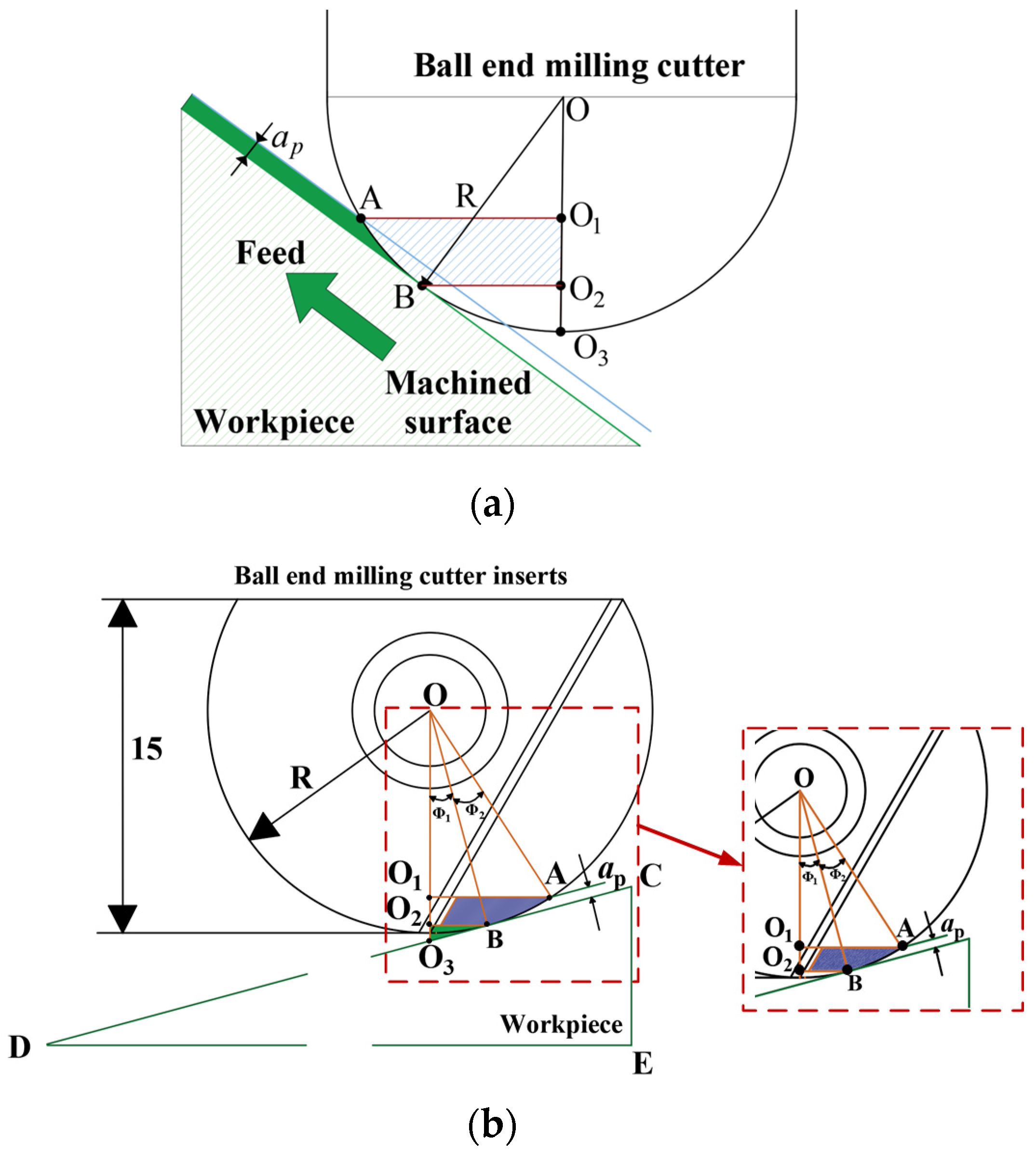
2.1. Carbide Ball End Milling Cutter Micro-Groove Distribution Location

Milling is a process in which a milling cutter with one or more teeth makes cuts with intermittent motion. Typically, a complete milling motion consists of a rotary motion of the milling cutter blade and shank being held on a spindle, with a feed motion of the workpiece in a fixture [26,27]. During the milling motion, the spindle speed at the tip position of the ball end milling cutter is constant at zero, which very easily causes wear on the milling cutter, affecting the machining quality of the product. Therefore, to improve the service life of the ball end milling cutter, side milling is usually used in milling, i.e., the ball end milling cutter is at a certain angle with the workpiece, which promotes the increase of the milling radius of the ball end milling cutter [28,29].
The workpiece selected in this paper for milling is a rectangular sample block of titanium alloy. To improve the machining accuracy and surface quality, the workpiece is tilted 15° as mounted on the fixture for the milling test [30,31]. By increasing the workpiece tilt to 15°, the ball end milling cutter can cut the edge part of the working area so that the cutting force and cutting heat are dispersed on the surface of the workpiece and, at the same time, are stored in the chip exclusion of the milling cutter; the workpiece mounting position is shown in Figure 1. Figure 1a shows the ball milling cutter and 15° tilt workpiece three-dimensional model; Figure 1b shows the milling process and the actual contact radius of the milling cutter with the workpiece at a fixed 15° tilt of the rectangular block, so the actual milling radius remains unchanged in the milling process at O1A.
To allow analysis of the effective working area of the ball end milling cutter blade during milling, the two-dimensional model of the milling cutter and the workpiece is shown in Figure 2. Mathematical calculation of the positional relationship between the milling cutter and the workpiece defines the workpiece as triangle CDE, with ∠CDE = 15°. Point A is the highest point of contact between the milling cutter and the chip (related to the milling depth), and point B is the lowest point of the milling cutter and the chip formation (for the point of contact with the workpiece material). Hence, the AB arc is the main working part of the milling cutter because the milling cutter is perpendicular to the horizontal plane; point A and B will be projected positively in the center of the ball end milling cutter as the milling cutter is perpendicular to the horizontal plane, point A and point B will be projected on the center of the ball end milling cutter to form points O1 and O2, and point O3 will be the tip of the ball end milling cutter. So, OO3⊥DE, is the milling cutter surface working area for O1O2BA. Because OB⊥CD, BO2⊥OO3, then ∠BO2O3 =∠CED = 90°; because O2B∥DE, then ∠O2BO3 = ∠CDE = 15°; and because OB⊥CD, then ∠O1OB = 15°, that is, Φ1 = 15°.
As shown in Figure 2, the maximum milling length is O1A, the minimum milling length is O2B, the milling depth is ap, and OB = OA = R, so that it can be expressed through Φ2 as follows:
Φ 2 = arccos ( R a p R )
Because OA = R, triangle OO1A is a right-angled triangle; the maximum milling radius O1A of the ball end milling cutter is given in Equation (3):
O 1 A = R sin ( Φ 1 + Φ 2 )
Because OB = R and triangle OO2B is a right-angle triangle, the minimum milling radius O2B is as given in Equation (3):
O 2 B = R sin Φ 1
Based on the actual specifications of the milling cutter, this article selects a CNC milling cutter radius of 10 mm and preliminarily selects a milling depth of 0.5 mm according to related references, which conforms to the parameter selection for actual milling usage. Therefore, through (2) and (3), it can be derived that Φ2 ≈ 18.1949°, the maximum milling length O1A ≈ 5.475 mm, and the minimum milling length O2B ≈ 2.588 mm. For O1A, for the actual milling radius of the ball end milling cutter, this paper sets the machine tool milling speed of 2500 rpm, 3000 rpm, and 3500 rpm. The actual instantaneous speed VC of point A on the milling edge relative to the main movement of the workpiece can be converted to 86 m/min, 103.2 m/min, and 120.4 m/min.

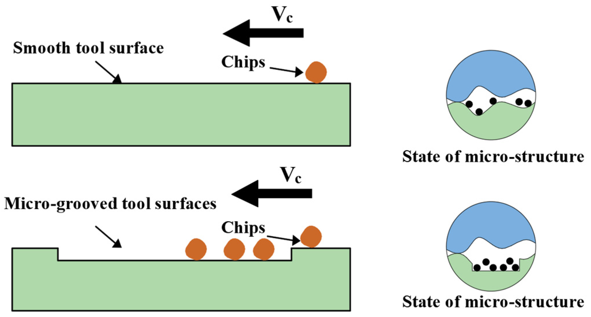
2.2. Sources of Micro-Grooves

Numerous research works have shown that by creating different micro-structures on the tool surface, the frictional properties of the tool surface can be reduced, lowering the coefficient of friction and, consequently, creating less friction on the tool surface [32]. Figure 3 shows the movement trajectories of chips on the smooth surface of the tool and on the surface of the micro-grooved structure, from which it can be seen that, in contrast to the smooth surface, the micro-grooved structure can be used as a storage container for tiny chips to avoid abrasive wear due to the extrusion of chips on the surface of the tool and the workpiece.
The surface of the shell is distributed with a grooved texture, in which the raised ridges prevent the impact of sediments; the groove structure can be used for the attachment and growth of sediments (algae) [33,34,35]. The shell surface has a prominent texture; the arrangement, size, and shape of the texture structure affect the hardness and impact resistance of the shell surface calcareous material. The shell surface groove morphology is shown in Figure 4. Measurement of the perlite structure on the shell surface, as shown in Figure 4b, yielded a two-dimensional interface map of the shell surface, as shown in Figure 4c, with a surface morphology of rectangular grooves interlaced with approximate depressions and projections, for which the extracted micro-groove shape is shown in Figure 4d.
Inspired by this, and considering the manufacturing of micro-grooves on the surface of milling cutters, the shell groove shape was applied to the edge of the milling cutter surface. A ball end mill with micro-grooves was manufactured using laser processing methods, and both finite element simulation tests and actual milling experiments were conducted to study the milling performance of the micro-grooved milling cutter.

3. Micro-Groove Milling Cutter Finite Element Simulation Test

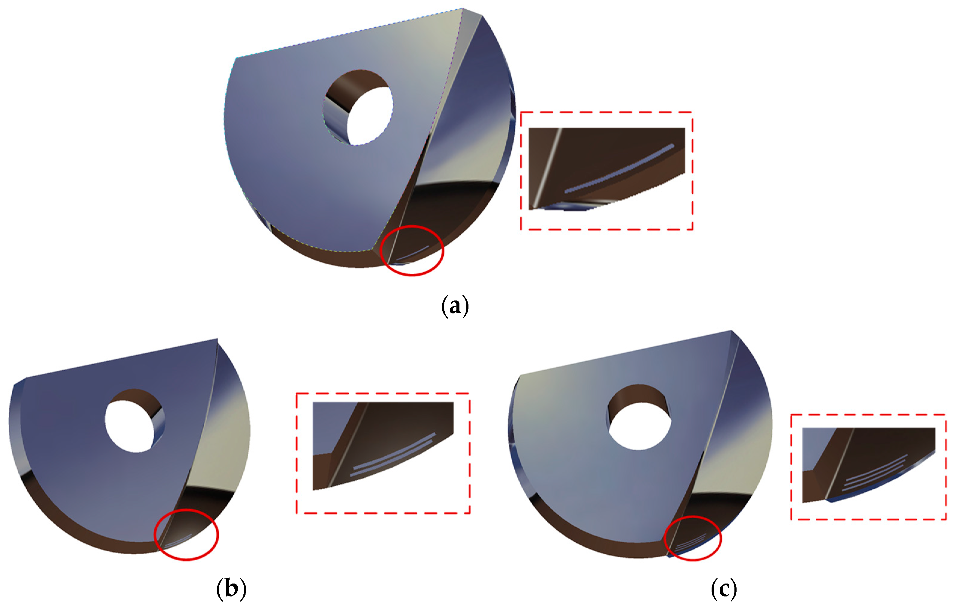
3.1. Establishment of 3D Model of Micro-Grooved Milling Cutter

To investigate the effect of micro-grooves in the milling cutter surface working area on the milling performance, using a design with micro-grooves of the same shape but different in number, AdvantEdge version 7.1 was utilized for the finite element software simulation. AdvantEdge is a dedicated metal cutting simulation software, software that provides a variety of standard models of the tool to simulate the results of different structure and process parameters, such as cutting forces and chip morphology changes [36,37]. The simulation of different structures and process parameters such as cutting force, tool temperature, and chip morphology are used in the customized tool model. In this paper, three kinds of micro-groove milling cutters are established, as shown in Figure 5, and ball end milling cutters with the number of micro-grooves of 1, 2, and 3 are defined as G1, G2, and G3. The dimensional parameters of the micro-grooves are a micro-groove spacing of 150 µm, width of 60 µm, depth of 60 µm, and distance from the main milling edge of 200 µm. The arc length of each micro-groove is determined to be 1200 µm, considering the effective working area of the milling cutter edge area and concerning the relevant literature [28,38]. Dimensional parameters of the three types of micro-groove milling cutters are shown in Table 1.

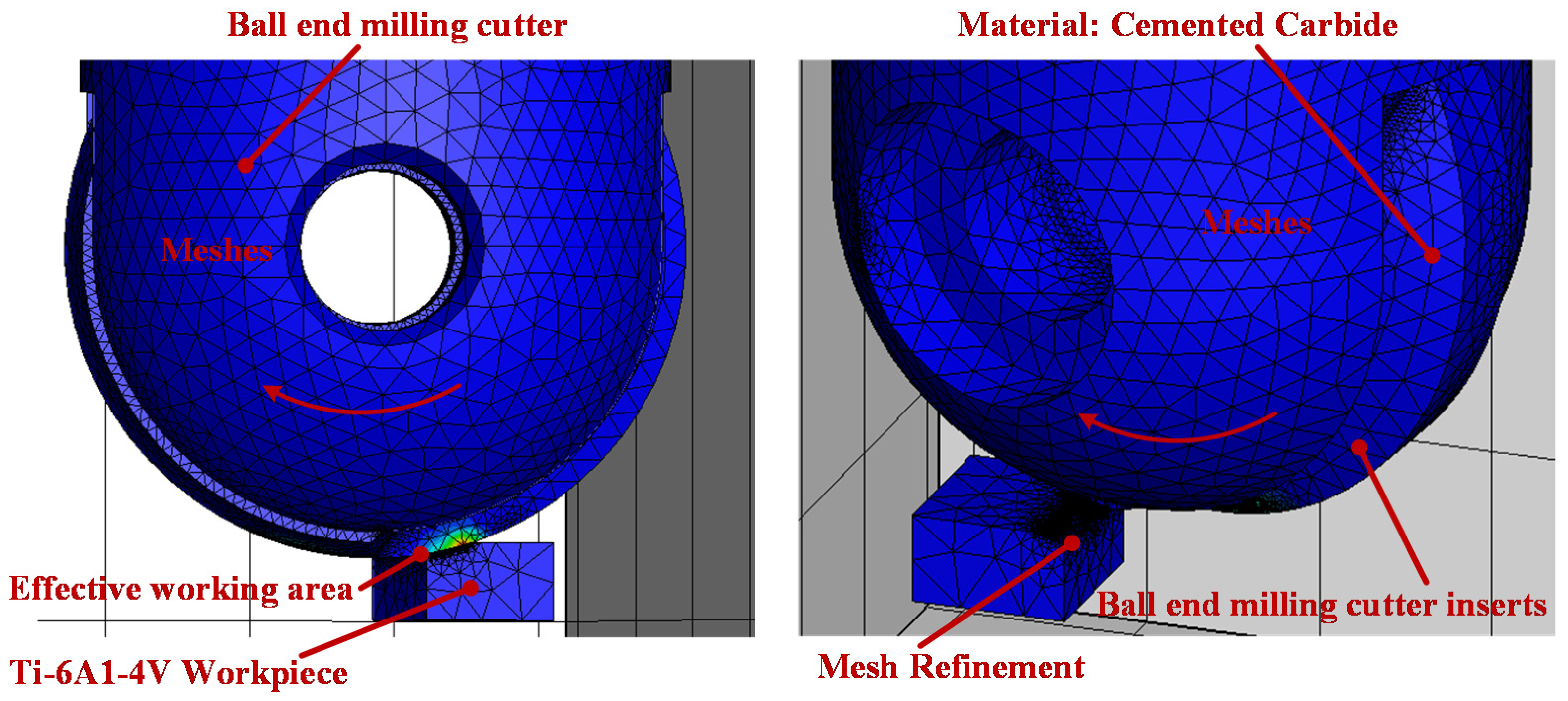
3.2. Finite Element Simulation Test of Milling by Micro-Grooved Milling Cutter

The designed micro-grooved milling cutter model is imported into the finite element simulation software, in order to obtain more accurate test results on the milling cutter and the workpiece mesh division; for the milling cutter distance from the milling area, the maximum mesh size is set to 0.1 mm; for the micro-grooved parts, the refinement of the mesh size is set to 0.01 mm; for the workpiece distance from the cutting layer, the maximum mesh size of the parts of the workpiece is set to 3 mm; for the workpiece surface of the cutting layer, the refinement of the minimum mesh size is set to 0.01 mm. The workpiece material is defined as titanium alloy, the size of the workpiece is defined as a rectangular block of 3 mm × 2 mm × 3 mm, and fixed constraints are applied to the bottom of the workpiece. The milling cutter material is defined as carbide, and the size of the milling cutter is a double-flute ball end milling cutter with a radius of 10 mm. During the milling process, the initial environmental temperature is set at 20 °C. The ball end mill rotates 360° during the simulation. In the metal-cutting process, the appropriateness of the friction model set between the chip and the tool directly affects the accuracy of the simulation results. This paper employs the Coulomb friction model for milling simulation, which accurately describes the friction state during the milling of titanium alloys, thereby enhancing the simulation’s accuracy. The finite element simulation mesh model of the milling cutter and workpiece is shown in Figure 6.
Ball milling cutters commonly use complex surfaces and process materials that are difficult to machine, usually according to the milling workpiece material processing hardness and tool life. To determine the range of milling parameters, this paper reviewed relevant references to ensure the premise of machining accuracy and to improve the processing efficiency; the milling parameters determined by the experimental group are shown in Table 2. We established a milling test schedule for the above-established three kinds of micro-groove milling cutter models and a group of milling cuttings without micro-groove structure milling simulation tests, to explore the micro-grooves in the milling work area and the milling speed to ensure high milling cutter performance.

3.3. Experimental Results and Analysis

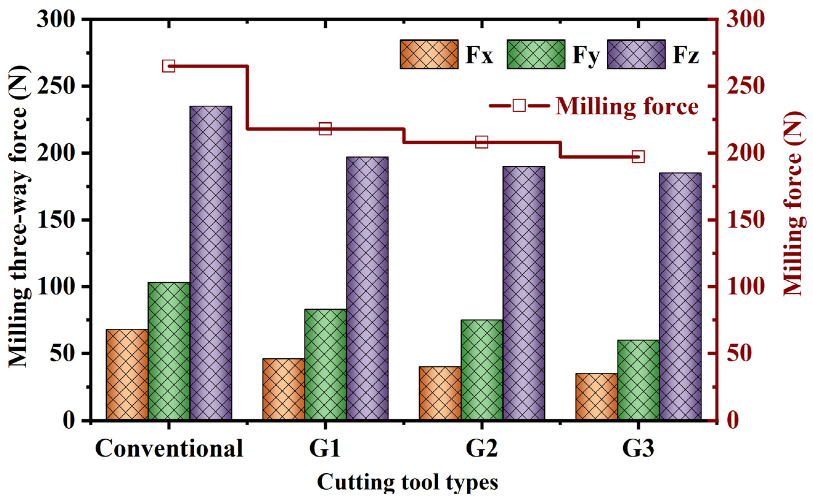
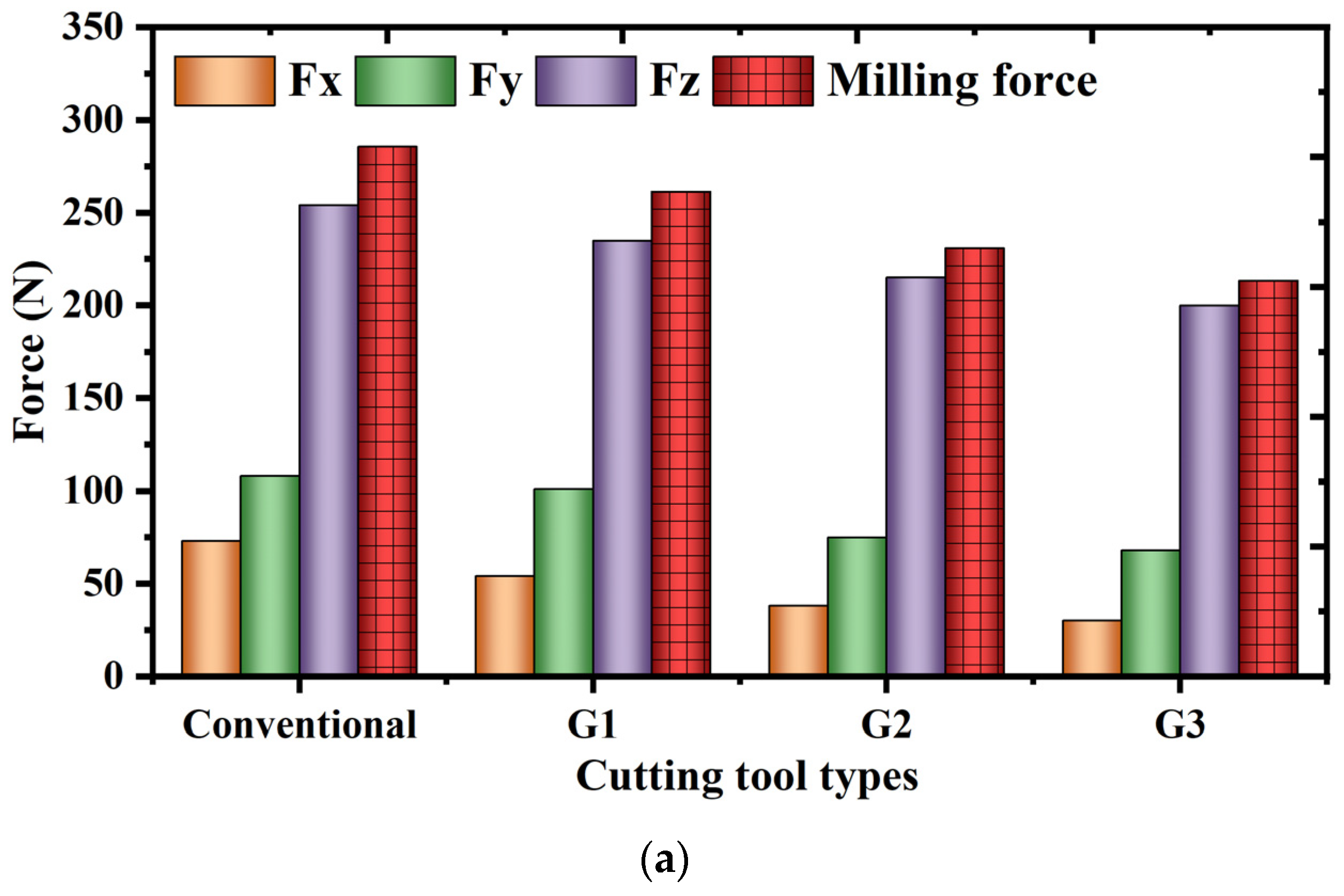
3.3.1. The Influence of Micro-Groove Count on Milling Force

When the spindle speed is 2500 rpm, to extract the triaxial milling forces generated during the simulation process using conventional milling cutters and three types of micro-groove milling cutters, 30 data points are selected to ensure the accuracy of the experimental results, and their averages are taken. Using the appropriate formula F x 2 + F y 2 + F Z 2 , the rational milling of conventional milling cutters and three types of micro-groove milling cutters is obtained. Figure 7 shows the influence of the number of micro-grooves on the milling force. The figure shows that compared to conventional milling cutters, the three types of micro-groove milling cutters promote a decrease in milling force. The G1 milling cutter promotes a 17.62% decrease in milling force; the G2 milling cutter promotes a 21.58% decrease in milling force; the G3 milling cutter promotes a 25.55% decrease in milling force. During the milling process, when the cutter enters the workpiece material, the surface of the workpiece material exhibits micro-elastic collision, and the internal strain zone shows plastic deformation, resulting in a sharp increase in milling force. As the milling progresses, the material of the workpiece removal layer begins to fracture, forming chips that overflow along the rake face, entering a stable milling state, and the milling force gradually stabilizes.
For micro-groove cutting tools, the insertion of micro-grooves on the milling cutter surface alters the friction state between the tool and the chips, reducing friction during the cutting process, thus playing a role in anti-wear and anti-friction, leading to a decrease in milling forces. It can be observed that as the number of micro-grooves increases, i.e., increasing the proportion of micro-grooves on the milling cutter surface, it is more conducive to the decrease in milling forces.
Milling belongs to intermittent machining; the insert force mode during milling is very complex, the magnitude of the force is related to the direction of the milling cutter, and the surface stress has a significant effect on the mechanical properties and fatigue life of the cutter. Figure 8 shows the change of x-direction stress during the simulation of four kinds of milling cutters at a spindle speed of 2500 rpm, from which it can be seen that the conventional milling cutter without micro-grooves has the largest area of stress distribution at the cutting edge, while the other three kinds of micro-groove milling cutters have stresses gradually spreading to the micro-groove part. It can be shown that the surface micro-groove can disperse the x-direction stresses generated during milling. Analysis of the milling cutter surface stress data shows that G1, G2, and G3 promote an x-directional stress reduction of 5.90%, 10.11%, and 13.76%, respectively, compared with the conventional milling cutter without micro-texturing. During the machining process, stresses are generated on the surface of the milling cutter due to the external forces on the material. When machining with a micro-grooved milling cutter, on the one hand, the stresses on the surface of the micro-grooved milling cutter are less than those of the conventional milling cutter due to the micro-groove on the surface, which promotes the decrease of the milling force. On the other hand, due to the micro-groove embedded in the surface of the milling cutter, the inner part of the micro-groove is perpendicular to the surface of the milling cutter, the edge of the micro-groove appears to have a sharp peak, and the micro-groove part is a certain distance away from the milling edge so that the high-stress area appears at the edge of the micro-groove.

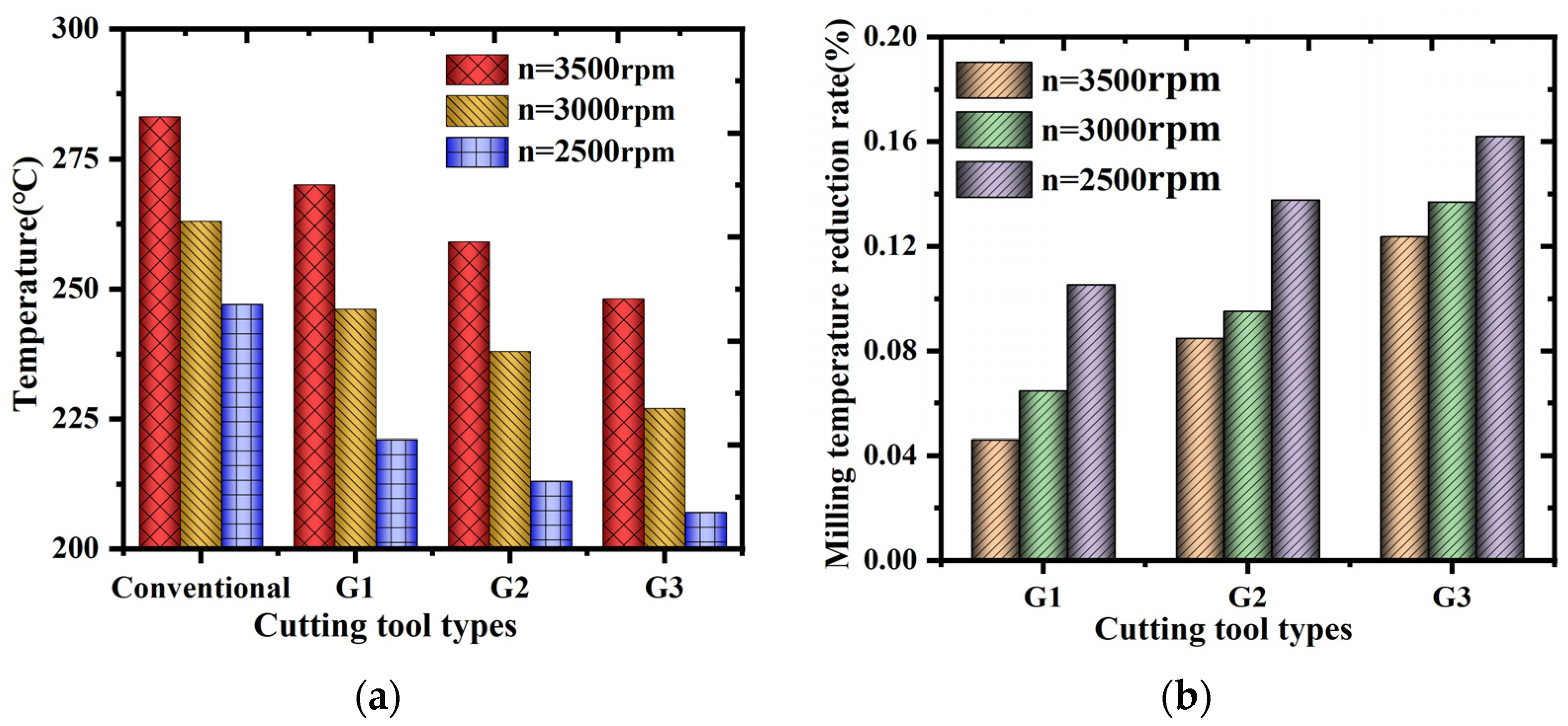
3.3.2. Effect of Micro-Grooved Area on Temperature

In the metal cutting process, the shear deformation of the chip and the friction of the tool surface of the work are transformed into cutting heat; under dry cutting conditions, the chip mainly removes the cutting heat, with a small portion of the residue in the milling cutter and the surface of the workpiece, and the temperature of the milling cutter edge part directly affects the wear of the surface of the milling cutter. Figure 9 represents the surface temperature distribution of the four types of milling cutters at a spindle speed of 2500 rpm.
From the graph, it can be observed that high-temperature regions are usually distributed at the tool’s cutting edge, and as the arrangement of micro-grooves gradually spreads inward, the temperature decreases gradually. As milling progresses, the temperature of the milling cutter continues to rise. The overall temperature rises sharply. This is because during the milling process, the milling motion causes chips to be created quickly, and the milling heat cannot be promptly be conducted between the tool and the chips, resulting in an excessive local temperature rise.
Figure 10 shows a conventional milling cutter and three kinds of micro-groove milling cutters under spindle speeds of n = 2500 rpm, n = 3000 rpm, and n = 3500 rpm. From the tip part of the milling temperature map in the figure, it can be seen that when the speed of the milling temperature gradually decreases for the three kinds of micro-grooved milling cutters, the milling temperature is significantly lower than that the conventional milling cutter. The milling temperature of the ball end milling cutter with three micro-grooves shows the most apparent decrease in the milling temperature.
At a milling cutter speed of 2500 rpm, compared to conventional milling cutters, the milling temperature decreased by 10.61%, 13.77%, and 16.19%, respectively, when machining with the G1, G2, and G3 ball end milling cutters. With the increase of spindle speed, the insert’s continuous working time is accelerated, the material removed per unit time is increased, and the heat piles up on the surface of the cutter, which is difficult to dissipate, resulting in heat build-up; this leads to an increase in the milling temperature. The reduction of milling temperature is mainly due to the tool and chip close contact area constructing a micro-groove; the existence of this micro-groove increases the heat exchange capacity of the tool surface, and tool surface air convection heat transfer area increases, prompting faster milling heat dissipation, resulting in the decline of the milling temperature.

3.3.3. The Influence of Micro-Groove Area on Chip Formation

For machining titanium alloy materials, due to the poor thermal conductivity and forming ability of titanium alloys, the chip outflow efficiency of the milling cutter surface is enhanced by placing micro-texturing on the tool surface under dry milling conditions. Figure 11 shows the chip outflow comparison between conventional milling cutters and three kinds of micro-grooved milling cutters under the spindle speed of 2500 rpm. It can be seen from the figure that the milling cutter easily produces small chips when machining titanium alloy materials; the chips are captured by the surface of the milling cutter, and with the machining of the chips for a long period, are extruded between the surface of the milling cutter and the workpiece material. This can easily cause abrasive wear on the cutter. For the micro-grooved milling cutter, the tiny chips on the surface of the cutter are captured by the micro-grooved part and stored inside, preventing wear of the milling cutter surface as caused by these tiny chips. Therefore, using micro-grooved milling cutters can effectively reduce the adhesion of titanium alloy chips during machining.
The above study shows that the micro-groove ball end milling cutter can reduce milling force, temperature, and stress, optimizing the milling cutter’s performance.

4. Micro-Groove Milling Cutter Test

4.1. Laser Fabrication of Micro-Groove Milling Cutters

This study employed laser processing to fabricate micro-groove milling cutters. The laser processing parameters were as follows: laser power 35 W, laser scanning frequency 800 mm, frequency 50 kHz, spot size 5 µm, and processing repetitions 25, with machining performed on the cutter surface. Based on the micro-groove milling cutter model established through milling simulation, a micro-groove ball end milling cutter consistent with the simulation was manufactured using a laser, as shown in Figure 12. During laser processing, residual milling cutter material powder is prone to remain inside the micro-grooves, affecting machining accuracy. Therefore, cleaning was conducted using an anhydrous ethanol solution and vibrating for 15–20 min in an ultrasonic cleaner; the processed milling cutter was used for milling experiments.

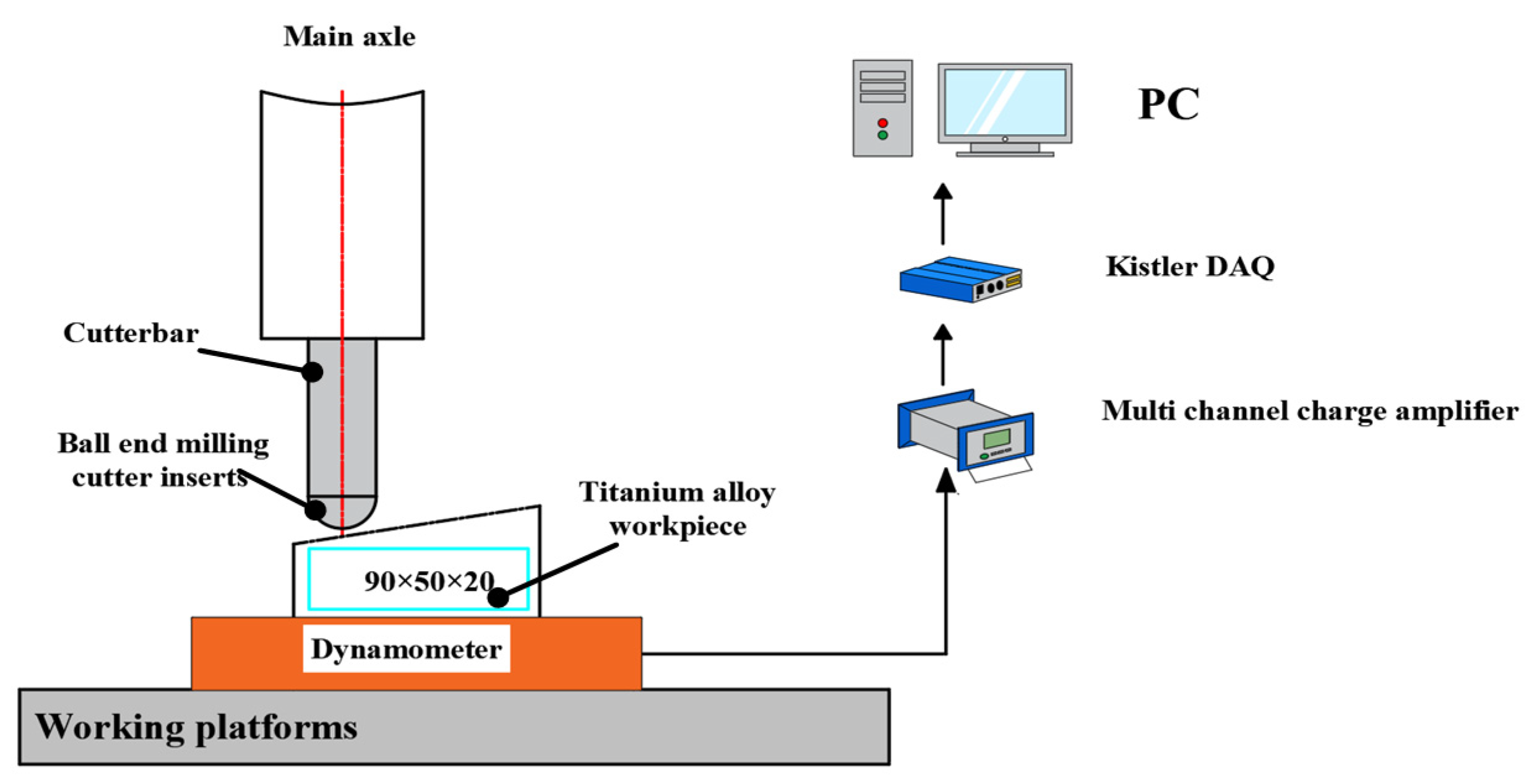
4.2. Micro-Groove Milling Cutter Test

The milling test uses a CNC milling machine model CMV-850A (TTGroup, Jiangsu, China). The workpiece material is titanium alloy Ti-6Al-4V. The workpiece sample is a rectangular block of 90 mm × 50 mm × 20 mm. The milling cutter blade adopts double-edged YG8 carbide inserts. The milling test bench is shown in Figure 13.
A Kistler 9527B force gauge was mounted on the bottom of the workpiece to measure the three-way milling force, a ZeGage™ Pro (Zygo Corporation, Middlefield, CT, USA) three-dimensional profiler was utilized to measure the post-processing surface roughness, and a Leica super depth-of-field microscope was used to observe the micro-groove milling cutter edge area and the resulting chip morphology. The milling tests were conducted with ball end milling inserts consistent with the simulation, and the milling parameters shown in Table 2 were used to conduct the milling tests of three types of micro-grooved milling cutters and one group of non-micro-grooved milling cutters. The titanium alloy workpiece is clamped at an angle of 15° between the plane to be machined and the horizontal plane of the machine guide, the milling method of down milling is adopted, and the milling distance of each type of milling cutter is 90 mm.

4.3. Milling Results and Analysis of Micro-Groove Milling Cutter

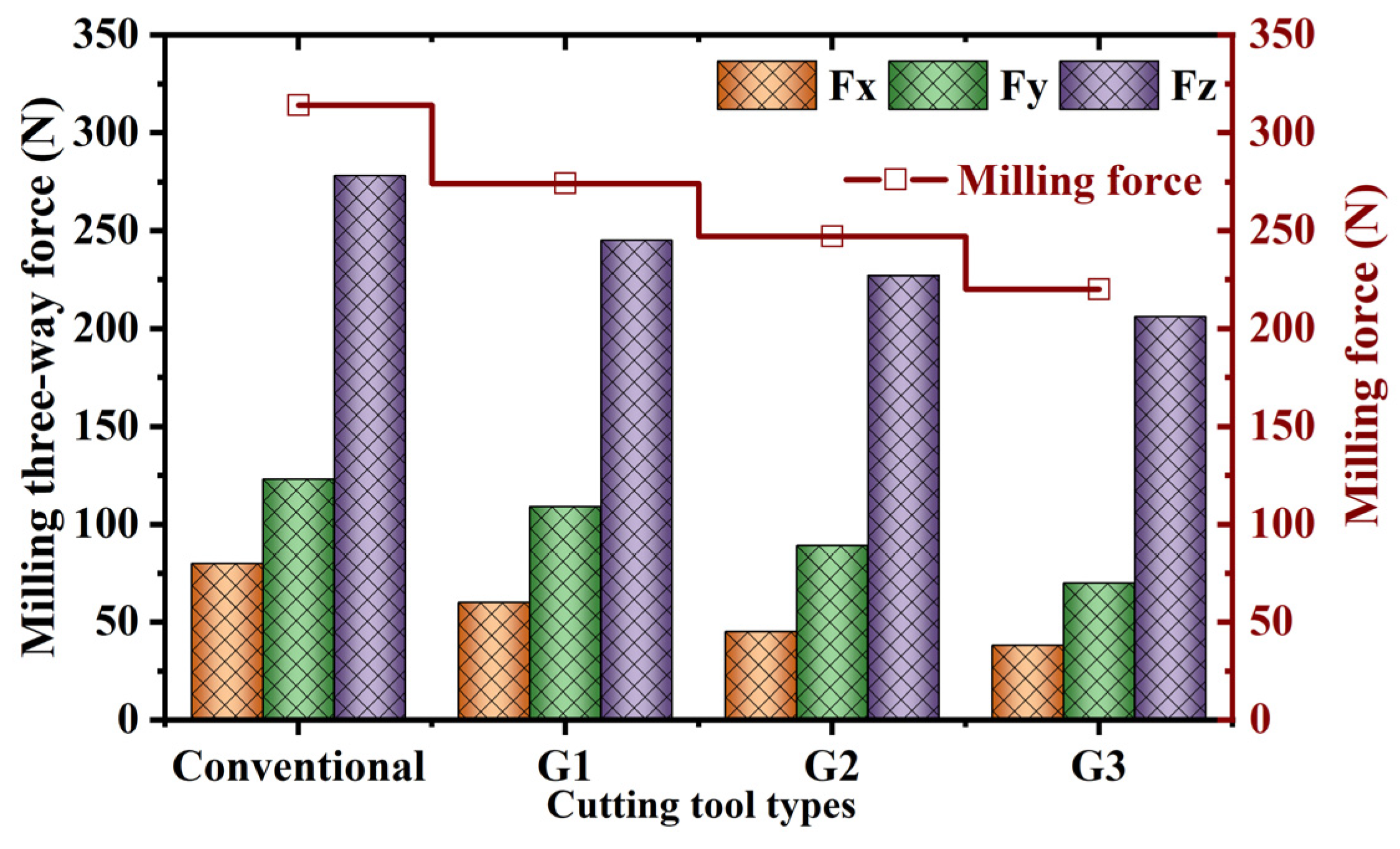
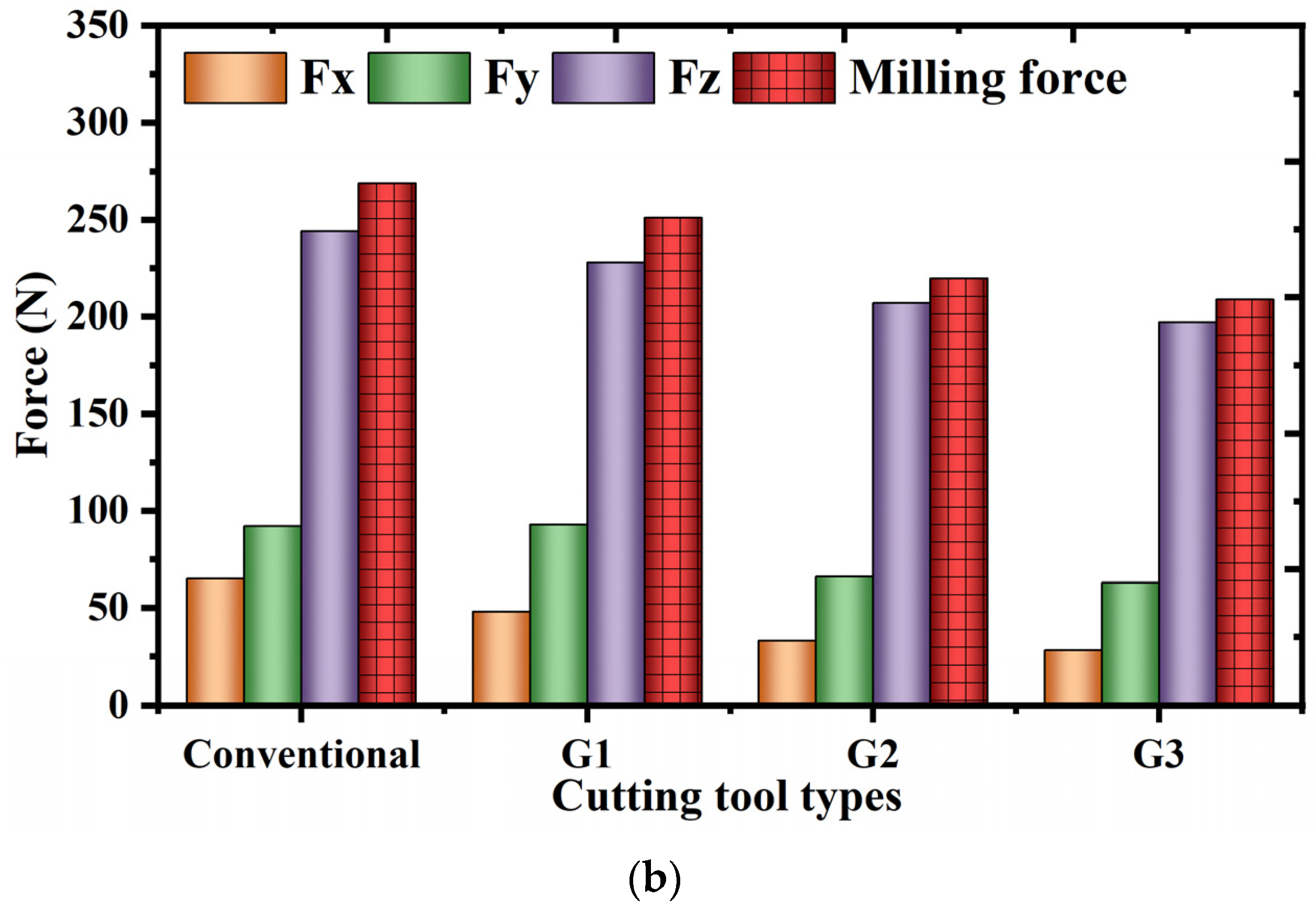
4.3.1. Impact of Micro-Groove Surface Area on Milling Forces

The milling force generated during the milling process of different micro-weaving milling cutters is determined using a force measuring instrument. Under the stable state of machining, several data points are selected for the measurement of milling force for each set of test results, and the average of the milling force for each set is calculated as a result of the test; the milling force of the conventional milling cutters and the three types of micro-groove milling cutters is shown in Figure 14.
From the figure, it can be seen that when the spindle speed is 3500 rpm, compared with the conventional milling cutter, the G1 milling cutter promotes a decrease of the milling combined force by 12.59%; the G2 milling cutter promotes a reduction in the milling combined force by 21.12%; and the G3 milling cutter promotes a reduction in the milling combined force by 29.72%. For the three micro-groove ball end milling cutters, with the increase of the number of micro-grooves, the contact area between the milling cutter and the chip decreases, which further promotes the change of the friction state; the heat dissipation area on the surface of the milling cutter increases, and the amount of chips captured by the micro-grooves increases, which gives full play to the friction-reducing and anti-wearing effect of the micro-grooves and further promotes the decrease of the average milling force. Comparative analysis of the milling test and simulation test with regard to the milling force shows that the trend of the influence of the number of micro-grooves on the milling force remains consistent, which can prove the accuracy of the simulation results and provide a theoretical basis for the next step of the study.
Figure 15 represents the changes in milling force under different spindle speeds. Figure 15a represents the changes in milling force when the spindle speed is 3000 rpm, from which it can be seen that compared with the conventional milling cutter, the G1 milling cutter promotes the decrease of the milling combined force by 8.43%; the G2 milling cutter promotes the decrease of the milling combined force by 19.14%; and the G3 milling cutter promotes the decrease of the milling combined force by 25.27%. Figure 15b shows the change of milling force when the spindle speed is 2500 rpm. From the figure, it can be seen that the G1 milling cutter promotes a decrease of the milling force by 7.97%; the G2 milling cutter promotes a decrease of the milling force by 18.23%; the G3 milling cutter promotes a decrease of the milling force by 22.34%. In the above analysis of the test results, it can be seen that compared with the conventional milling cutter without micro-grooves, the micro-groove milling cutter promotes a decrease of the milling force, and with the increase of the number of grooves, the milling performance of the micro-groove milling cutter is enhanced.

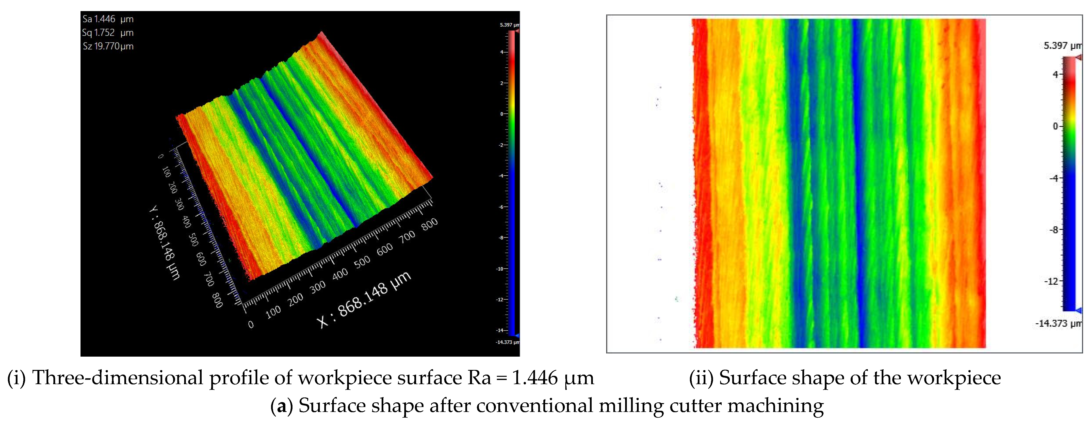
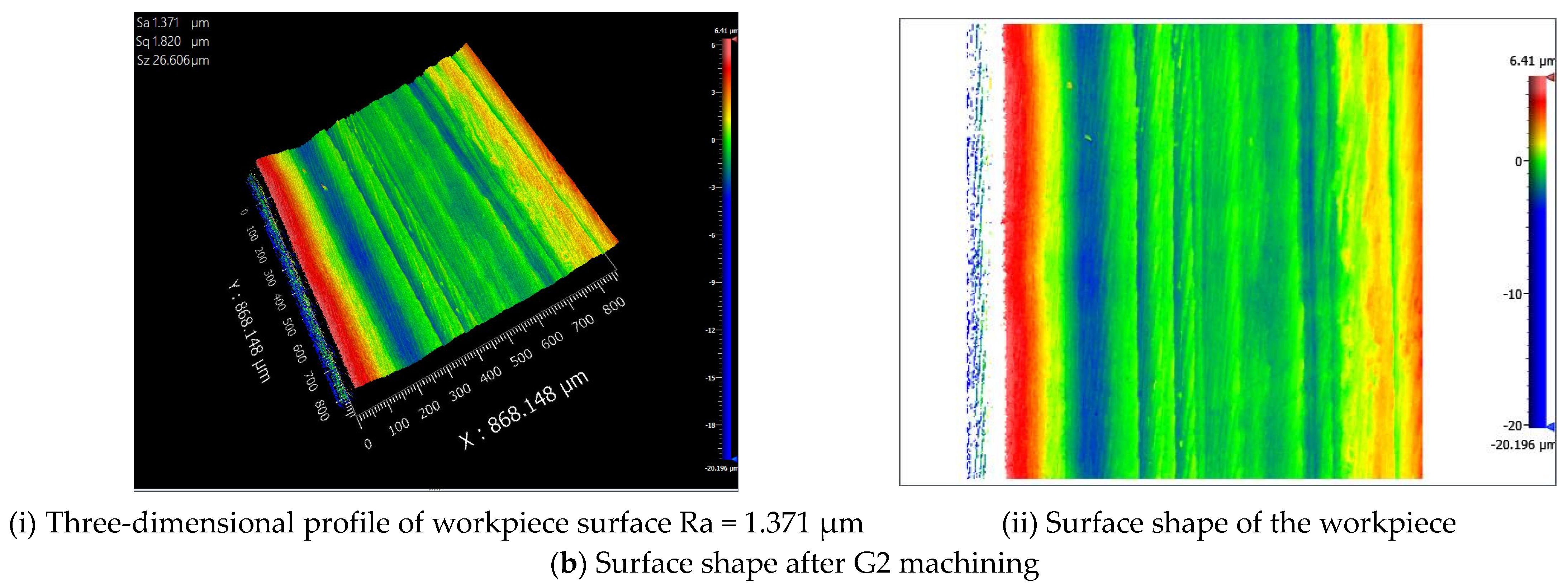
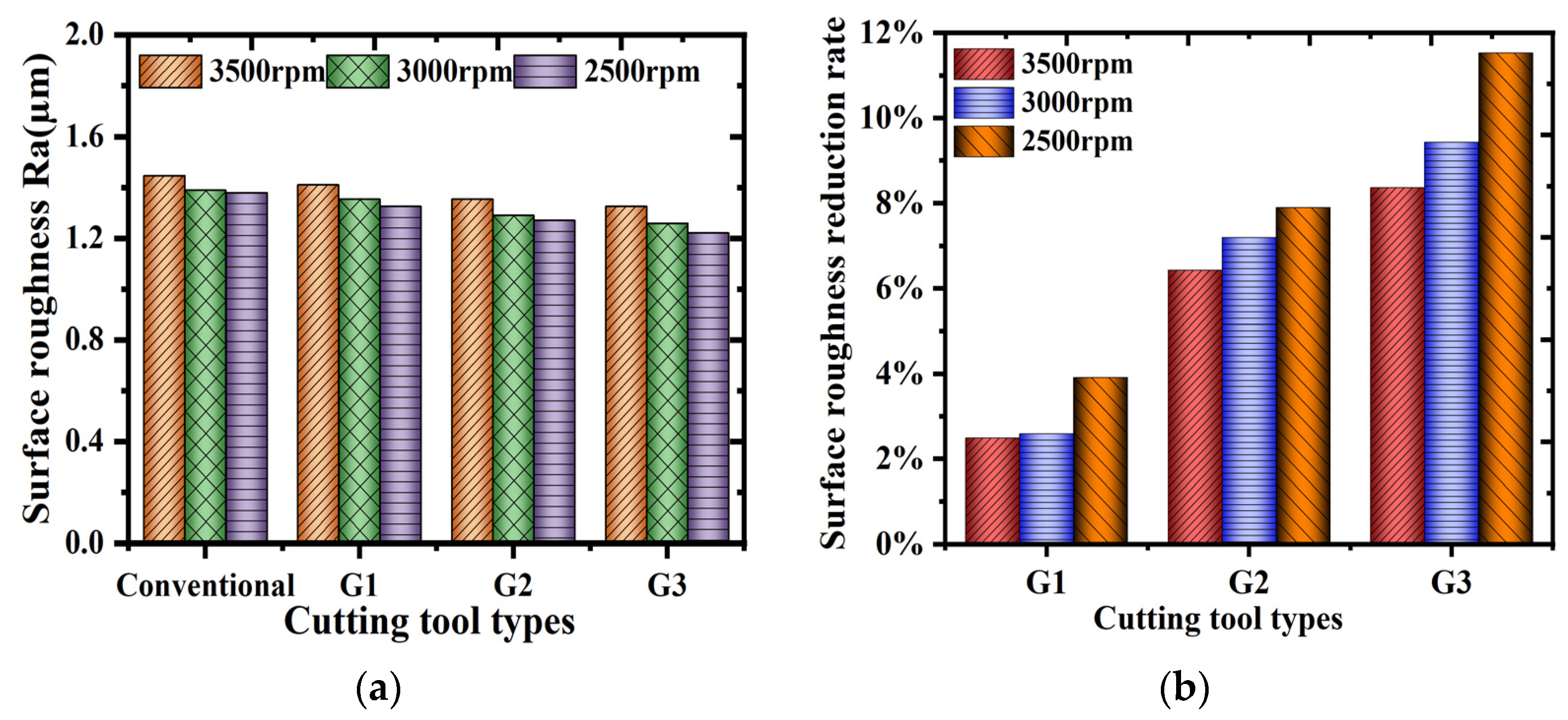
4.3.2. Effect of Micro-Groove Area on Surface Roughness of Machined Workpiece

The machined parts’ surface roughness directly affects the parts’ service life. In this paper, the surface roughness of the machined workpieces was measured using a ZeGage™ Pro type optical profiler. The milling parameters used in the milling test are shown in Table 2. A conventional milling cutter and three kinds of micro-groove milling cutters were used for the milling test, and the milling distance of each type of milling cutter was 90 mm. Figure 16 shows the surface morphology of the workpieces after machining by the conventional milling cutter and the G2 milling cutter with a milling speed of 3500 rpm. The figure shows that the surface roughness of the workpiece after machining with the conventional milling cutter is 1.446 µm and that of the workpiece after machining with the G2 milling cutter is 1.371 µm. Thus, it can be seen that the G2 milling cutter contributes to reducing the surface roughness after machining.
In order to ensure the accuracy of the test, when the milling is completed, the surface roughness of the workpiece is measured; each group of surfaces is measured three times, and the average value is taken as the test result. The surface roughness of the workpiece is plotted in Figure 17, which shows that the four types of milling cutters are processed at milling speeds of 2500 rpm, 3000 rpm, and 3500 rpm. From Figure 17a,b, it can be seen that at a spindle speed of 3500 rpm, the surface roughness of the ball end milling cutters G1, G2, and G3 decreases by 2.49%, 6.43%, and 8.37%, respectively, compared to that of the conventional milling cutter; at a spindle speed of 3000 rpm, the surface roughness of the ball end milling cutters G1, G2, and G3 decreases by 2.59%, 7.20%, and 9.43%, respectively, compared to that of the conventional milling cutter; at a spindle speed of 2500 rpm, the surface roughness of the groove micro-weave is decreased by 2.59%, 7.20%, and 9.43%, respectively; at a spindle speed of 2500 rpm, the surface roughness of the ball end milling cutters G1, G2, and G3 decreased by 3.92%, 7.90%, and 11.53%, respectively, compared with that of the conventional milling cutter. Therefore, compared with the conventional milling cutter, the surface roughness of the workpiece after machining is significantly reduced when using the micro-grooved milling cutters, and the surface micro-groove further reduces the contact area between the tool and the chip, which contributes to the reduction of the frictional resistance generated by the chip flows through the cutter surface and enhances the milling performance.

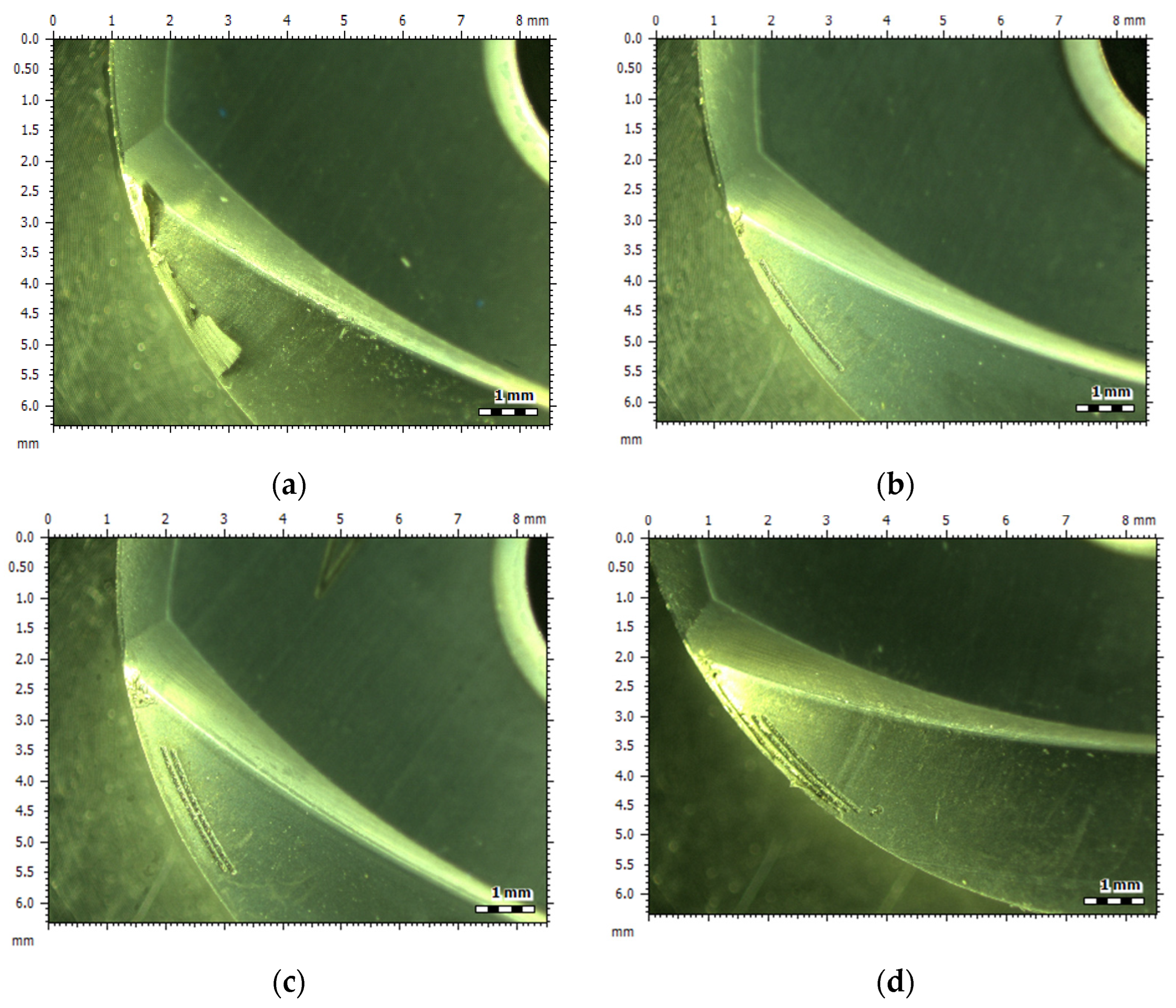
4.3.3. Effect of Micro-Groove Area on Chip Adhesion Resistance

The surface morphology of the milling cutter was measured after milling was completed using a Leica ultra-fine depth microscope, and Figure 18 shows the chip adhesion on the surface of the conventional and micro-grooved ball end milling cutter tools after milling a titanium alloy specimen with a length of 90 mm using four types of milling cutters with exact milling parameters at n = 3500 rpm. It can be observed from the figure that when using conventional milling cutters, chips adhere to the surface of the cutter, while for micro-groove cutters, a small amount of debris adheres at the milling edge. For micro-groove ball-nose cutters, the working process of the micro-groove can be divided into three stages: at the start of milling, the layer of material on the workpiece breaks under the external load, forming chips that overflow along the surface of the cutter, with a small amount of tiny debris stored inside the micro-grooves; as milling progresses, tiny debris accumulates and is pressed into the micro-grooves, gradually filling them up; in the later stages of milling, the filled micro-groove area is under high pressure for a long time, causing stress concentration on the cutter surface, and under the action of repeated cyclic stress, this leads to wear on the surface of the cutter. When using a cutter with three micro-grooves, the number of micro-grooves working at the cutting edge increases, enlarging the space for heat exchange and the heat dissipation area on the cutter surface, thus improving the heat transfer effect, reducing the surface temperature of the cutter, and alleviating the phenomenon of chip adhesion.
Using the Leica Ultra Precision Microscope (Leica Microsystems, Mannheim, Germany), the chips generated using the G3 milling cutter at different spindle speeds were collected, as shown in Figure 19. It can be seen from the figure when the spindle speed is high, the deformation of the cutting layer on the workpiece is severe within the same time, the chip formation speed accelerates, the chips accumulate in the milling cutter surface work area, causing a local temperature rise in the milling cutter, and the phenomenon of chip adhesion is prone to occur. When using a conventional milling cutter for milling, the milling cutter surface and chip make direct contact, and a large number of chips overflow and remove a large amount of heat. When there is a small amount of chip residue on the milling cutter surface, the milling cutter blade local temperature rises and thus increases the chip adhesion, resulting in the tool surface occurrence of a “cold weld”, affecting the machining quality. For the micro-groove milling cutter, to avoid direct contact between the tool and chips, the surface of the micro-groove can be used as a storage container for chips, reducing the friction on the surface of the milling cutter and, at the same time, increasing the heat dissipation area of the surface of the milling cutter, which contributes to the enhancement of the milling performance.
The study shows that when micro-grooved milling cutters are used in milling experiments, they help reduce the milling force by 10% to 30%, achieving good consistency with simulations. When a cutter with three micro-grooves is used, it promotes an 8% to 12% reduction in surface roughness of the machined workpiece while also alleviating the phenomenon of chips adhering to the milling cutter surface.

5. Conclusions

To explore the impact of micro-grooving on the surface of milling cutters on their milling performance, this paper calculates the effective working position of the milling cutter blades based on the milling parameters and the installation positions of the milling cutter and the workpiece. Inspired by the arrangement of perlite on the surface of seashells, micro-grooves are applied to the milling surface. A micro-grooved ball milling cutter is manufactured, utilizing the friction-reducing and wear-resistant mechanisms of micro-grooves on the cutter surface to optimize the milling performance. The effectiveness is verified through finite element simulation tests and actual milling experiments, yielding the following conclusions:
  • Through finite element simulation experiments on milling titanium alloys, it was found that compared to conventional milling cutters, micro-groove milling cutters promote a reduction in milling force and temperature, enhance chip resistance to adhesion, and change the concentration location of high stress areas on the surface of the milling cutter. Meanwhile, it was found that milling force, milling cutter surface stress, and milling temperature decreased significantly as the area occupied by micro-grooves on the milling cutter surface increased.
  • Milling experiments showed that micro-grooved ball end mills help reduce milling forces, achieving good simulation consistency. When using a cutter with three micro-grooves, the milling force decreased by 10% to 30%, and the surface roughness decreased by 8% to 12%. It was also found that as the spindle speed increases, the curling radius of the chip decreases.
  • The test results prove that preparing micro-grooves in the working area of the milling cutter surface changes the friction state between the milling cutter and chips, increases the heat dissipation area of the milling cutter surface, and allows the micro-grooves to be used as a storage container for chips, improving the resistance of the milling cutter surface to chip adhesion.

Author Contributions

S.Z.: writing of manuscript, charting, data collection, literature retrieval; H.S.: document retrieval, data collection, data analysis; B.W.: document retrieval, charting; C.M.: data collection, data analysis; Q.L.: research ideas, experimental design, data analysis. All authors have read and agreed to the published version of the manuscript.

Funding

We thank the following for their strong support: “Natural Science Foundation of Jilin Province-General Project, Study on the Machinability of Milling Titanium Alloy with Micro-texture Milling Cutter” (20220101227JC).

Data Availability Statement

Data will be made available on request.

Acknowledgments

The authors would like to thank the members of the project team for their dedication and efforts, and the teachers and schools for their help.

Conflicts of Interest

The authors declare no conflicts of interest.

References

  1. Han, P.; Tong, X.; Yang, S.; Wang, X. Uniform-Density Micro-Textured Ball-End Milling Cutter Model Based on Fractal and Uniform Distribution Theory. Coatings 2023, 13, 1446. [Google Scholar] [CrossRef]
  2. Patil, S.; Jadhav, S.; Kekade, S.; Supare, A.; Powar, A.; Singh, R.K.P. The influence of cutting heat on the surface integrity during machining of titanium alloy Ti6Al4V. Procedia Manuf. 2016, 5, 857–869. [Google Scholar] [CrossRef]
  3. Zhang, Y.; Ji, H. Wear optimization of titanium alloy cutter milled with microtextured ball-end milling cutter. Adv. Mech. Eng. 2020, 12, 1687814019892102. [Google Scholar] [CrossRef]
  4. Cotterell, M.; Byrne, G. Dynamics of chip formation during orthogonal cutting of titanium alloy Ti–6Al–4V. CIRP Ann. 2008, 57, 93–96. [Google Scholar] [CrossRef]
  5. Taylor, C.M.; Hernandez, S.G.A.; Marshall, M.; Broderick, M. Cutting fluid application for titanium alloys Ti-6Al-4V and Ti-10V-2Fe-3Al in a finish turning process. Procedia CIRP 2018, 77, 441–444. [Google Scholar] [CrossRef]
  6. Khanna, N.; Davim, J.P. Design-of-experiments application in machining titanium alloys for aerospace structural components. Measurement 2015, 61, 280–290. [Google Scholar] [CrossRef]
  7. Arulkirubakaran, D.; Senthilkumar, V.; Kumawat, V. Effect of micro-textured tools on machining of Ti–6Al–4V alloy: An experimental and numerical approach. Int. J. Refract. Met. Hard Mater. 2016, 54, 165–177. [Google Scholar] [CrossRef]
  8. Özel, T.; Biermann, D.; Enomoto, T.; Mativenga, P. Structured and textured cutting tool surfaces for machining applications. CIRP Ann. 2021, 70, 495–518. [Google Scholar] [CrossRef]
  9. Dogra, M.; Sharma, V.S.; Sachdeva, A.; Suri, N.M.; Dureja, J.S. Tool wear, chip formation and workpiece surface issues in CBN hard turning: A review. Int. J. Precis. Eng. Manuf. 2010, 11, 341–358. [Google Scholar] [CrossRef]
  10. Varga, J.; Ižol, P.; Vrabeľ, M.; Kaščák, Ľ.; Drbúl, M.; Brindza, J. Surface Quality Evaluation in the Milling Process Using a Ball Nose End Mill. Appl. Sci. 2023, 13, 10328. [Google Scholar] [CrossRef]
  11. Karpat, Y. Investigating elastic recovery of monocrystalline silicon during plunging experiments with chamfered diamond tools. Precis. Eng. 2023, 84, 119–135. [Google Scholar] [CrossRef]
  12. Khani, S.; Razfar, M.R.; Haghighi, S.S.; Farahnakian, M. Optimization of microtextured tools parameters in thread turning process of aluminum 7075 aerospace alloy. Mater. Manuf. Process. 2020, 35, 1330–1338. [Google Scholar] [CrossRef]
  13. Kümmel, J.; Braun, D.; Gibmeier, J.; Schneider, J.; Greiner, C.; Schulze, V.; Wanner, A. Study on micro texturing of uncoated cemented carbide cutting tools for wear improvement and built-up edge stabilisation. J. Mater. Process. Technol. 2015, 215, 62–70. [Google Scholar] [CrossRef]
  14. Ribeiro, F.S.F.; Lopes, J.C.; Bianchi, E.C.; de Angelo Sanchez, L.E. Applications of texturization techniques on cutting tools surfaces—A survey. Int. J. Adv. Manuf. Technol. 2020, 109, 1117–1135. [Google Scholar] [CrossRef]
  15. Yang, S.; Su, S.; Liu, X.; Han, P. Study on Milling Temperature of Titanium Alloy with Micro-Textured Ball End Milling Cutter under Radius of Blunt Edge. Appl. Sci. 2020, 10, 587. [Google Scholar] [CrossRef]
  16. Tong, X.; Liu, X.; Yang, S.; Wang, L.; He, C. Optimising milled titanium alloy concave surface quality with micro-textured ball-end milling cutters. Int. J. Manuf. Res. 2021, 16, 122–134. [Google Scholar] [CrossRef]
  17. Patel, K.; Liu, G.; Shah, S.R.; Özel, T. Effect of micro-textured tool parameters on forces, stresses, wear rate, and variable friction in titanium alloy machining. J. Manuf. Sci. Eng. 2020, 142, 021007. [Google Scholar] [CrossRef]
  18. Zheng, K.; Yang, F.; Zhang, N.; Liu, Q.; Jiang, F. Study on the cutting performance of micro textured tools on cutting Ti-6Al-4V titanium alloy. Micromachines 2020, 11, 137. [Google Scholar] [CrossRef]
  19. Li, Q.; Yang, S.; Zhang, Y.; Zhou, Y.; Cui, J. Evaluation of the machinability of titanium alloy using a micro-textured ball end milling cutter. Int. J. Adv. Manuf. Technol. 2018, 98, 2083–2092. [Google Scholar] [CrossRef]
  20. Alagan, N.T.; Zeman, P.; Hoier, P.; Beno, T.; Klement, U. Investigation of micro-textured cutting tools used for face turning of alloy 718 with high-pressure cooling. J. Manuf. Process. 2019, 37, 606–616. [Google Scholar] [CrossRef]
  21. Yang, F.; Pan, C.; Shi, Y. Fabricating Micro-texture on Surface of Cutting Tool Based on NC WEDM Technology. In IOP Conference Series: Earth and Environmental Science; IOP Publishing: Bristol, UK, 2020; Volume 440, p. 022084. [Google Scholar]
  22. Kumar, V.U.; Raj, D.S. Performance analysis of tools with rake face textures produced using wire-EDM in turning AISI4340. Mater. Manuf. Process. 2021, 36, 1146–1160. [Google Scholar] [CrossRef]
  23. Sharma, R.; Pradhan, S.; Bathe, R.N. Design and fabrication of honeycomb micro-texture using femtosecond laser machine. Mater. Manuf. Process. 2021, 36, 1314–1322. [Google Scholar] [CrossRef]
  24. Puoza, J.C.; Hua, X.; Liu, Q.; Kang, Z.; Zhang, P. Manufacturing of micro-textures on metals by nanosecond laser micromachining. Adv. Mater. Process. Technol. 2018, 4, 86–99. [Google Scholar] [CrossRef]
  25. Sun, X.; Wang, X.; Hu, Y.; Duan, J.A. The effect of micro-texture on wear resistance of WC/Co-based tools during cutting Ti-6Al-4V. Appl. Phys. A 2021, 127, 453. [Google Scholar] [CrossRef]
  26. Phokobye, S.N.; Daniyan, I.A.; Tlhabadira, I.; Masu, L.; VanStaden, L.R. Model design and optimization of carbide milling cutter for milling operation of M200 tool steel. Procedia CIRP 2019, 84, 954–959. [Google Scholar] [CrossRef]
  27. Pan, J.; Ni, J.; He, L.; Cui, Z.; Feng, K. Influence of micro-structured milling cutter on the milling load and surface roughness of 6061 aluminum alloy. Int. J. Adv. Manuf. Technol. 2020, 110, 3201–3208. [Google Scholar] [CrossRef]
  28. Li, Q. Design Guidelines and Experimental Study of Micro-Texture of YG8 Ball End Milling Cutter for Cutting Titanium Alloy. Master’s Thesis, Harbin Institute of Technology, Harbin, China, 2019. [Google Scholar]
  29. Yang, S.; Han, P.; Tong, X.; Liu, X.; Zhang, X. Study on forming technology of mesoscopic geometric features of tools and its role. J. Mech. Eng. 2024, 60, 317–351. [Google Scholar]
  30. Yang, S.; Yu, S.; He, C. The surface integrity of titanium alloy when using micro-textured ball-end milling cutters. Micromachines 2018, 10, 21. [Google Scholar] [CrossRef]
  31. Yang, S.; Han, P.; Su, S.; Zhang, N.; Ren, W. Study on surface work hardening of titanium alloy milled by micro-textured ball milling cutter. Int. J. Adv. Manuf. Technol. 2021, 112, 2497–2508. [Google Scholar] [CrossRef]
  32. Kishawy, H.A.; Salem, A.; Hegab, H.; Hosseini, A.; Balazinski, M. Micro-textured cutting tools: Phenomenological analysis and design recommendations. CIRP Ann. 2021, 70, 65–68. [Google Scholar] [CrossRef]
  33. Yang, S. Research on the Design and Cutting Performance of PCBN Bionic Tool Based on the Tooth Profile Conformation of Cap Shell Teeth. Master’s Thesis, Harbin Institute of Technology, Harbin, China, 2023. [Google Scholar]
  34. Wang, B.; Zhu, J.; Xie, T.; Fu, L.; Yang, W.; Li, D.; Zhou, L. A new Cu-W bionic shell pearl multilayer structure. Surf. Coat. Technol. 2023, 461, 129433. [Google Scholar] [CrossRef]
  35. Jia, H. Strong Woven Research on Three-Dimensional Graphene Oxide-Based Biomimetic Shell Pearl Layer Block Material. Master’s Thesis, Taiyuan University of Technology, Taiyuan, China, 2020. [Google Scholar]
  36. Li, R.; Zhao, X. Analysis of the effect of shape factor on stress field and temperature field. Mach. Tools Hydraul. 2020, 48, 134–137. [Google Scholar]
  37. Zhao, X.; Zou, Z.; Shi, H.; He, L.; Hu, X. Simulation analysis of the influence of micro milling cutter geometry parameters on TC4 alloy machining. Comb. Mach. Tools Autom. Mach. Technol. 2020, 9–13. [Google Scholar] [CrossRef]
  38. Tong, X.; Yang, S.; He, C.; Zheng, M. Multiobjective optimization of cutting performance of ball end milling cutter with variable density micro-weave configuration. J. Mech. Eng. 2019, 55, 221–232. [Google Scholar]
Figure 1. Mounting position of the milling cutter and workpiece.
Lubricants 12 00204 g001
Figure 2. Two-dimensional model of milling cutter and workpiece. (a) Effective contact area; (b) two-dimensional calculation of effective contact area.
Lubricants 12 00204 g002
Figure 3. Mechanism of micro-groove effects.
Lubricants 12 00204 g003
Figure 4. Morphology of grooves on shell surface.
Lubricants 12 00204 g004
Figure 5. Micro-grooved milling cutter. (a) G1; (b) G2; (c) G3.
Lubricants 12 00204 g005
Figure 6. Workpiece and milling cutter meshing.
Lubricants 12 00204 g006
Figure 7. Effect of the number of micro-grooves on the milling force.
Lubricants 12 00204 g007
Figure 8. Effect of the number of micro-grooves on stresses. (a) Conventional tools; (b) G1; (c) G2; (d) G3.
Lubricants 12 00204 g008
Figure 9. Effect of the number of micro-grooves on the cutting temperature. (a) Conventional tools; (b) G1; (c) G2; (d) G3.
Lubricants 12 00204 g009
Figure 10. Milling temperature of milling cutters with different numbers of micro-grooves. (a) Effect of spindle speed on milling temperature; (b) rate of decrease in milling temperature.
Lubricants 12 00204 g010
Figure 11. Influence of micro-grooves on chip overflow. (a) Conventional tools; (b) G1; (c) G2; (d) G3.
Lubricants 12 00204 g011
Figure 12. Micro-groove ball end milling cutter surface shape. (a) G1; (b) G2; (c) G3.
Lubricants 12 00204 g012
Figure 13. Milling test platform.
Lubricants 12 00204 g013
Figure 14. Effect of spindle speed n = 3500 rpm for micro-grooved milling cutters.
Lubricants 12 00204 g014
Figure 15. Effect of the number of micro-grooves on the milling force. (a) Spindle speed n = 3000 rpm; (b) spindle speed n = 2500 rpm.
Lubricants 12 00204 g015aLubricants 12 00204 g015b
Figure 16. Surface morphology of machined workpiece.
Lubricants 12 00204 g016aLubricants 12 00204 g016b
Figure 17. Surface workpiece roughness after micro-groove milling cutter machining. (a) Effect of the number of micro-grooves on surface roughness; (b) rate of surface roughness reduction.
Lubricants 12 00204 g017
Figure 18. The adhesion condition of chips on the surface of the milling cutter. (a) Conventional tools; (b) G1; (c) G2; (d) G3.
Lubricants 12 00204 g018
Figure 19. Effect of spindle speed on chip morphology. (a) 3500 rpm; (b) 3000 rpm; (c) 2500 rpm.
Lubricants 12 00204 g019
Table 1. Micro-groove size parameters.
Dimensional
Parameters
Spacing
(μm)
Length
(μm)
Width
(μm)
Depth
(μm)
Numerical Value15012006060
Table 2. Processing parameters used in finite element analysis.
GroupSpindle Speed
n (rpm)
Feed per Tooth
f (mm/z)
Depth of Cut
ap (mm)
125000.10.5
230000.10.5
335000.10.5
Disclaimer/Publisher’s Note: The statements, opinions and data contained in all publications are solely those of the individual author(s) and contributor(s) and not of MDPI and/or the editor(s). MDPI and/or the editor(s) disclaim responsibility for any injury to people or property resulting from any ideas, methods, instructions or products referred to in the content.

