Article

Modelling of Static and Dynamic Elastomer Friction in Dry Conditions

by
Fabian Kaiser
*,
Daniele Savio
and
Ravindrakumar Bactavatchalou
Freudenberg Technology Innovation SE & Co. KG, Hoehnerweg 2-4, 69469 Weinheim, Germany
*
Author to whom correspondence should be addressed.
Lubricants 2024, 12(7), 250; https://doi.org/10.3390/lubricants12070250
Submission received: 29 May 2024 / Revised: 21 June 2024 / Accepted: 24 June 2024 / Published: 9 July 2024
(This article belongs to the Special Issue Tribology in Germany: Latest Research and Development)

Abstract

:
Understanding the tribological behavior of elastomers in dry conditions is essential for sealing applications, as dry contact may occur even in lubricated conditions due to local dewetting. In recent decades, Persson and co-authors have developed a comprehensive theory for rubber contact mechanics and dry friction. In this work, their model is implemented and extended, particularly by including static friction based on the bond population model by Juvekar and coworkers. Validation experiments are performed using a tribometer over a wide range of materials, temperatures and speeds. It is shown that the friction model presented in this work can predict the static and dynamic dry friction of various commercial rubber materials with different base polymers (FKM, EPDM and NBR) with an average accuracy of 10%. The model is then used to study the relevance of different elastomer friction contributions under various operating conditions and for different roughness of the counter surface. The present model will help in the development of novel optimized sealing solutions and provide a foundation for future modeling of lubricated elastomer friction.

1. Introduction

Many academic institutions and companies have a long history in the research of sealing components. Nevertheless, there are still some significant aspects of rubber seals that are not fully understood. One example is the physical interactions happening in the frictional contacts of dynamical seals. From the perspective of Freudenberg as a sealing and lubricant manufacturing company, improved understanding of such tribological phenomena in sealing contacts is crucial.
When designing new sealing elements and novel elastomers for sealing applications, engineers must strike a balance between several, sometimes conflicting, requirements. On the one hand, tightness, i.e., the primary sealing function, must be ensured. On the other hand, efficient designs with high lifetime, i.e., with controlled friction and wear, are also desired. Ultimately, developers must rely on a good understanding of tribological and sealing behavior under a wide range of operating conditions to ensure design efficiency and reliability. This need applies to several sealing components. The classical example is the radial shaft seal, which heavily relies on friction at the sealing edge to ensure proper operation during shaft rotation [1]. However, even static seals like O-rings can undergo motion once systems are pressurized or depressurized [2], typically after long standstill times.
Predictive friction models for elastomers in dry and lubricated conditions will help speed up the development process in terms of seal design and material selection, improve the transferability between tests and actual product operation and give valuable guidelines for the development of new materials. All of this will reduce costs and/or increase sales.
Such models must consider several aspects of a tribological contact. First, typical engineering surfaces are rough, and, when pressed together, do not come into contact everywhere, which has been well known since the ground-breaking work by Greenwood and Williamson [3]. Adhesive or abrasive friction processes take place at these contact spots [4]; close to the contacts, additional losses occur through viscoelastic damping in elastomers when they slide on a hard, rough counterface. Extensive theoretical developments on the calculation of the contact area between rough surfaces were performed by Persson [5]. In the past 20 years, his theory has been extensively tested [6] and extended, e.g., for adhesion [7], layered materials [8] or plasticity [5,9]. It has also been applied successfully to calculate the static leakage of polymeric [10,11,12] and metallic seals [13], the latter including elastoplastic material behavior, as a function of surface roughness. Other numerical methods have also been used to predict sealing performance of systems under operation, e.g., Boundary Element Methods for metallic face seals [14] or Finite Element Analysis for rubber sealing cylinders [15].
In terms of solid body friction, Persson’s seminal paper from 2001 already considered viscoelastic dissipation in rubbery materials [5]. More recent developments also consider other sliding friction contributions acting in the contact spots [16,17]. It should be noted that most of the papers on friction focus on tire compounds, seeing limited application to sealing elastomers [18] up to now.
An additional aspect to consider is the presence of fluids in the contact—be it specialized lubricants or simply the sealed media—which can reduce solid-body contact and friction through different mechanisms. At high speeds, hydrodynamic lift separates the surfaces, resulting in the well-known Stribeck curve [19]. This is modeled through the well-established Reynolds equation [19]. The effect of surface roughness on flow is either modeled deterministically or accounted for by flow factors from homogenization approaches [20] and from contact mechanics results [21]. At low sliding speeds, the boundary lubrication regime is deeply affected by wettability effects (i.e., the spreading coefficient) between the elastomer, counterface and lubricant [22] (Figure 1). First modeling approaches are presented in the literature [23,24], but many aspects, particularly regarding the interaction with roughness, are still unknown.
Overall, the state of the art lacks a theory coupling realistic roughness contact, material properties and surface–fluid wetting interactions which determine friction under boundary lubrication. To fill this gap, a necessary step is to improve our modeling of dry elastomer friction, since this constitutes the main reference to compare the lubricating action of different fluids (see Figure 1). Moreover, unlubricated contact spots will likely persist even in presence of lubricants [23], and their contact and friction behavior must be correctly quantified before envisioning an extension to surface–fluid wetting.
In this work, we tackle the following aspects of dry elastomer friction. First, we test the applicability of state-of-art friction models [16] to typical sealing elastomers in a wide range of sliding speeds and temperatures and compare their results to tribological experiments. Second, we analyze which friction contributions are the most relevant in typical sealing systems. Third, we propose an extension of the current theory to quantify breakloose friction as a function of standstill time.

2. Materials and Methods

2.1. Experimental Methods

2.1.1. Elastomer Materials and Their Characterization

We consider four commercial fully formulated elastomer compounds with various base polymers (FKM, NBR and EPDM). An overview is provided in Table 1: all materials except FKM 2 were provided by Freudenberg Sealing Technologies. FKM 2 was acquired from a different supplier. All materials come in 2 mm thick slabs, from which different samples for material characterization or tribological testing are punched out.
Dynamic Mechanical Analysis (in shear mode, with a 1% strain amplitude) is performed for each elastomer using a dynamical–mechanical material tester EPLEXOR 2000N (GABO Qualimeter GmbH, Germany). The machine performs temperature and frequency sweeps, which are automatically combined into master curves through a WLF shift procedure [25]. A typical example is provided in Figure 2, showing the frequency evolution of the storage and loss moduli G ( ω ) and G ( ω ) and the loss tangent tan ( δ ) for FKM 1. We consider rubber incompressible (i.e., Poisson ratio of ≈0.5) in all conditions.

2.1.2. Surfaces and Their Characterization

Surface topography data for the elastomers and the steel counterface are measured using White Light Interferometry (WLI) on a Bruker NPFLEX device. The measured domains were approximately 1.3 × 1.7 mm2 large, with a lateral resolution of 1.27 µm in both epitaxial directions. On each material, measurements were performed 2–3 times to ensure that statistically representative surface patches were selected.
Figure 3a shows the ground 1.2842 (90MnCrV8) steel countersurface used in the tribological experiments: one can note the anisotropic features typical of its manufacturing process.
For the elastomers, topography measurements were performed mainly on worn surfaces. In fact, our tribological tests show that the skin from the rubber molding process is usually removed after very few sliding cycles, so a worn state is representative of most of the experiment. Figure 3b presents a typical example showcasing the isotropic nature of the worn elastomer roughness.
In our simulations based on Perssons’ theory, height data needs to be transformed into their power spectral density [9]—also called PSD or C ( q ) , where q = ( q x ,   q y ) is the wavevector. After removing tilt and curvature from measured data, followed by Hann windowing [26], the PSD can be calculated through an FFT algorithm [27]. Radially averaged power spectra for selected worn elastomers are shown in Figure 3d. Due to their similar magnitude and slope, all curves were averaged into one (the solid black line), which we used in our calculations as a representative worn rubber surface. The radially averaged PSD for ground steel is also depicted in Figure 3c, together with the PSD curves for the x and y directions. In the calculations, we employed the full C ( q x ,   q y ) to account for anisotropy. Note that the PSD of the roughness parallel to the surface “grooves” ( x -direction) is comparable to the angular average of a polished surface.

2.1.3. Tribological Testing

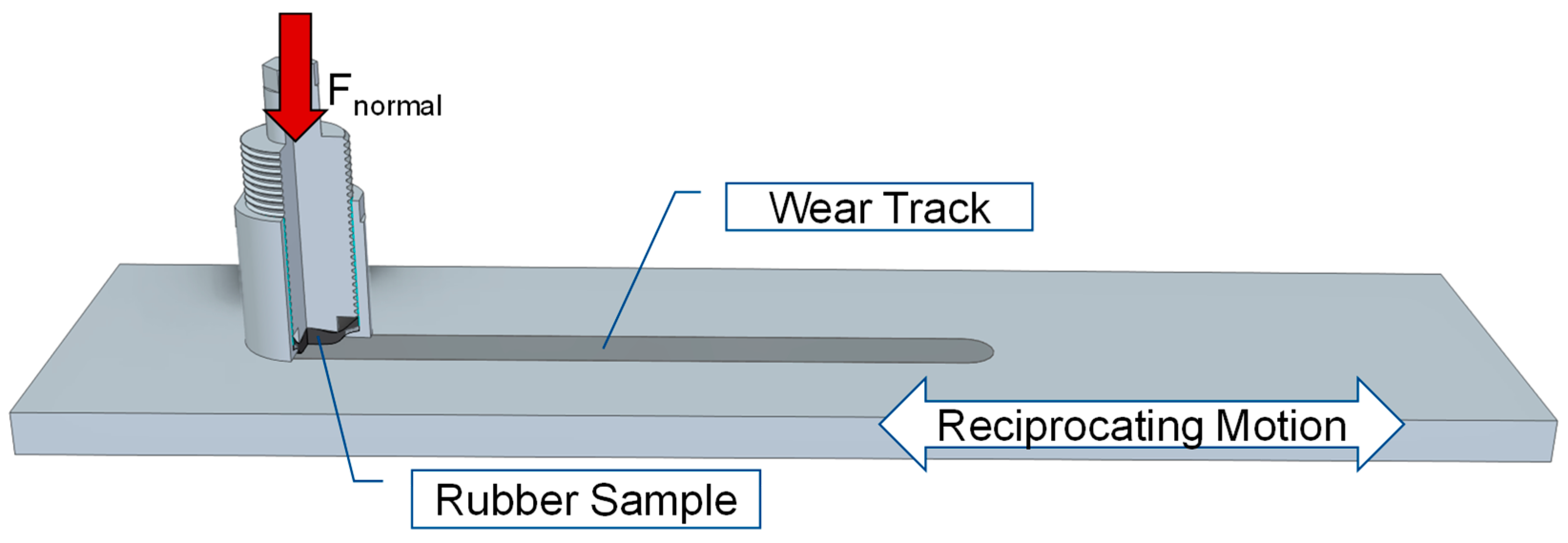
A custom-built reciprocating test rig was used to measure static and dynamic friction of the rubber materials. In this setup (see Figure 4), the elastomer samples are normally loaded using a pressurized pneumatic bellow. The reciprocating counterface motion relative to the rubber is driven by a linear motor with speeds ranging from 0.5 mm/s to 1 m/s. The setup is installed in a climate chamber (Binder MKF 720) that allows testing of friction and wear between −40 °C and 150 °C. The experimental parameters used for the rubber materials are listed in Table 2.
The normal and friction force are measured using force transducers (Burster 8524, Burster Präzisionsmesstechnik, Gernsbach, Germany and ME KD80s, ME-Meßsysteme, Henningsdorf, Germany, respectively). The static friction value is defined as the maximum friction force when relative movement starts after waiting, and the dynamic friction value is averaged over the central 30 mm of the 50 mm stroke when conditions are steady.
Punched elastomer discs (2 mm thickness and 20 mm diameter) are installed in a specially designed pin. After mounting, the rubber samples assume a spherical shape with a radius of curvature of approx. 22 mm to the rubber (see Figure 4). This way, reliable friction testing can be achieved using readily available rubber sheets, while avoiding edge effects typical of flat pins with sharp borders. The geometry and chosen loading conditions result in an average contact pressure of approx. 1.3 MPa, which is in line with typical sealing applications. The setup allows for reproducible measurements without noticeable friction instabilities, e.g., stick-slip, over the whole speed and temperature range.

2.2. Simulation Methods

2.2.1. Contact Area Calculation

When the rubber is pushed against the counterface with a given external load F N the nominal contact area A 0 and pressure σ 0 = F N / A 0 can easily be calculated using analytical (e.g., Hertzian) formulations or finite element methods.
Friction processes are, however, strongly dependent on the true area of contact A true , generally a small fraction of A 0 in the case of rough surfaces. Both A true and the relative contact area A rel = A true / A 0 between the elastomer surface and steel counterface can be predicted using Persson’s theory. The reader can refer to several papers for its derivation [5,28] and comparisons to other calculation methods [6]. At its core, this theory involves solving a diffusion equation for the probability distribution of contact stresses P ( σ , q ) with increasing high-frequency surface roughness content:
P q = f q 2 P σ 2 .
The diffusion coefficient f ( q ) depends on the nominal contact pressure σ 0 = F N / A 0 , the combined roughness power spectral density C q = C q elastomer + C q steel and the equivalent contact modulus E * . As the rubber accommodates most of the deformation, E * = 1 + 2 ν 1 + ν 2 G * ( T , ω ) , where G * ( T , ω ) is the temperature and frequency dependent shear modulus of the rubber from DMA and ν = 0.5 is its Poisson’s ratio.
Our numerical implementation of Equation (1) includes quartic correction factors for the elastic energy and stress broadening from [29]. Once solved for the probability distribution of contact stresses P ( σ , q ) , the relative contact area is obtained:
A r e l q = P σ , q d q .

2.2.2. Dynamic Elastomer Friction and Its Contributions

The elastomer friction model used in this work bases on recent works by Persson and coworkers [16]. Here, three main contributions to friction are considered:
μ total = μ contact + μ viscoelastic + μ crack .
Their physical meaning, where they occur and details on their modeling are discussed below.
μ contact : This contribution acts in the real contact area between rough surfaces, and can be expressed as follows [16]:
μ contact = τ f A r e l σ 0 + μ transfer .
The two terms correspond to separate friction mechanisms. In the first, polymer chains attach to the countersurface, are stretched and finally detach, dissipating the stored energy as friction losses. According to [16], the resulting interfacial shear stress τ f is expressed as a semi-empirical master curve:
τ f v = τ 0   exp c log 10 v v 0 2 ,
where v is the current sliding speed and v 0 = 1   mm / s is a fixed reference velocity. Both the dimensionless constant c 0.25 and the maximum shear stress τ 0 at v = v 0 are elastomer-dependent parameters.
The master curve in Equation (5) relies on an Arrhenius-type shifting to calculate the frictional shear stress τ f v , T = τ f a T T v at different temperatures. The shift factor a T is given by [16]:
ln a T = ϵ k B 1 T 1 T 0 1 ( T g 20 K ) + 1 T g , 0   .
Here, the reference temperatures T 0 = 20   ° C for the master curve Equation (5) and T g 0 = 38   ° C for the glass transition are fixed [30]. T g is the glass transition temperature of the bulk elastomer, with a correction of 20 K accounting for the lower T g of thin polymer films compared to the bulk material [16]. Finally, the activation energy ϵ is an elastomer-dependent parameter of the order of 1 eV.
For the commercial rubber materials for sealing applications tested in this work, we found that τ 0 in Equation (5) can be expressed as:
τ 0 T = E * T k ,
where the factor k is a material-dependent constant of order unity.
Overall, the resulting bonding friction coefficient τ f A rel / σ 0 shows a bell-like dependence with the sliding speed. Although the model from Equations (5)–(7) appears of empirical nature, it can match more complex theories accounting for the molecular mechanisms of the bonding process in the contact zones. In [31], rate constants for bond formation and breakage were related to the bond activation energy and the strain energy acting on stretched chains during sliding, ultimately resulting in a dimensionless expression for the shear stress:
τ ^ = τ T , v τ 0 τ * = 1 V ^ exp u V ^ 1 + 1 V ^ exp u V ^ E 1 u V ^ G 1 u V ^ l n u V ^ E 1 u V ^ ,
where E 1 and G 1 are exponential integral functions defined as:
E 1 x = x e y y d y ,               G 1 x = x e y y ln y d y .
Other quantities in Equation (8) are the dimensionless sliding velocity V ^ ( T ) = a T T v / v 0 , the bond activation energy parameter u and the shear stress scaling factor τ * .
As the models proposed in [16,31] both describe the bonding friction contribution as a function of the sliding velocity, they should provide similar results. One can thus seek suitable relationships between the parameters of Equations (5)–(7) and u ,   τ * in Equations (8) and (9). Based on a numerical parametric study, the following heuristic expressions were obtained for the calculation of u and τ * :
u = exp 0.578 c + 0.0325 1 ,               τ * = 1.8 c + 0.0384 1 .
Table 3 summarizes all friction model parameters for the four considered elastomers.
The second friction contribution in Equation (4), i.e., μ transfer , accounts for the formation and shearing of an elastomer transfer film in the contact spots. This process occurs in almost all tribological applications involving dry sliding of rubber, where the molding skin of the elastomer is quickly worn and deteriorated polymer chains adhere to the counter surface, forming a thin rubbery layer. In our experiments, such transfer films form and contribute to the friction coefficient at all speeds and temperatures—i.e., regardless of whether the elastomer displays a rubbery or a glassy response. The exact physical origin of this contribution is still unclear: it has been attributed to hard fillers of the elastomer scratching the counter surface [17] or the thermoplastic-like behavior of the rubber material in its glassy state [16]. We speculate that it may be due to inter-chain friction between the chains still attached to the polymer and those transferred to the counterface. This would explain why it is present at all temperatures and speeds, as well as with elastomers that have no hard fillers capable of scratching the counterface. In any case, friction related to the shearing of the transfer film can be best quantified at temperatures below glass transition, where other contributions to the friction coefficient vanish. For the simulations presented here, we use μ transfer = 0.4 , in good agreement with [16].
μ viscoelastic : Viscoelastic friction occurs in a bulk elastomer in contact with a rough hard countersurface, whose asperities lead to a pulsating excitation and energy losses in the rubber as sliding occurs. The viscoelastic dissipation is highest at excitation frequencies corresponding to the maximum of the loss modulus of the elastomer. Persson and coworkers have developed a comprehensive model to calculate this contribution in prior decades [5], including a model to calculate the local temperature increase due to the sliding [32,33] which is also incorporated in the present model.
μ viscoelastic = 1 2 q q 3 C q S q A rel ( q ) 0 2 π cos ϕ   I m   E * ( q v cos ϕ , T q ) σ 0 d ϕ d q ,
where the correction factor S q has been adapted from [29]:
S q = 1 2 9 1 A rel q 2 2 3   1 A rel q 4 .
In Equation (11), I m E * is the loss modulus of the elastomer at the contact temperature T q and frequencies related to the sliding speed v and roughness wavevector q . The factor cos ϕ and the related integral account for the angle between the sliding direction and roughness at different wavelengths, so that the impact of anisotropic roughness on viscoelastic friction is modeled correctly. One can also recognize further contributions of the surface roughness in C ( q ) and of the relative contact area A r e l ( q ) .
μ crack : the crack opening contribution to friction occurs at the edges of the real contact area as two surfaces are separated under pull-off, rolling or sliding. The opening of the contact edge is similar to a Mode-I crack propagating in the rubber material, causing viscoelastic losses depending on the crack radius, propagation speed and the dimension of the contact spots [34,35]. This friction contribution is relevant for rolling contacts, but under pure sliding it is expected to only play a minor role on total friction [35].

2.2.3. Static Friction Model and Its Contributions

We now propose an extension of the dry dynamic friction model to account for breakloose friction as a function of different standstill times t standstill . Coherent with the experiments, the static friction coefficient μ static = τ static / σ 0 is calculated from the maximum shear stress τ static occurring at the onset of sliding.
One should note that, although established in tribology, the wording “static friction” is a misnomer, as it implies the absence of motion in the system. In reality, microscopic movements occur at the onset of sliding, be it through a deformation of the bulk materials [36] and localized siding [37,38], or creep [39] at the sliding interface. Ultimately, it is reasonable to assume that the same friction phenomena occurring in the contact zones under dynamic conditions, i.e., under macroscopic sliding, also apply to the microscopic motion of the breakloose process.
Thus, our static friction model is based on the contributions discussed in the previous section, with some changes:
μ static = τ f , static σ 0 A rel , static + μ transfer + μ viscoelastic A rel , static + μ crack A rel , static .
The main difference is a modified contact area A rel , static accounting for relaxation and creep of the elastomer during standstill under a given normal load. Its calculation employs the softer contact modulus E * ( t s t a n d s t i l l ) , which leads to an increased contact area compared to sliding conditions. Apart from the constant μ t r a n s f e r , all other friction contributions scale up with the ratio A r e l , s t a t i c / A r e l , s l i d i n g , which can become large when the elastomer has a glassy response under sliding and a rubbery state during standstill.
The static friction model also employs a modified definition of the bonding shear stress τ f , static , based on an adapted bond population model from [39]. Here, the time evolution of interfacial shear stress is expressed in terms of bond formation, bond breaking due to strain and the resulting interfacial creep velocity through the following set of dimensionless differential equations (adapted from [39]):
d N ^ w d t ^ = 1 N ^ w N ^ s N ^ w   u exp τ ^ w N ^ w ,             d N ^ s d t ^ = N ^ s   u exp τ ^ s N ^ s , d τ ^ w d t ^ = d N ^ w d t ^ τ ^ w N ^ w + N ^ w   V ^ c ,             d τ ^ s d t ^ = d N ^ s d t ^ τ ^ s N ^ s + N ^ s   V ^ c , d ( τ ^ w + τ ^ s ) d t ^ = V ^ V ^ c .
Here, t ^ is the dimensionless time, N ^ is the number of interfacial bonds, u the bond activation energy parameter, V ^ the applied speed, V c ^ the interfacial creep velocity and τ ^ the shear stress. Indexes s and w refer to two types of interfacial bonds: so-called strong bonds, created in the standstill phase, and weak bonds, created in the breakloose phase, i.e., the time required to achieve macroscopic motion.
Initial conditions for Equation (14) are N ^ w = τ ^ w = τ ^ s = 0 and N ^ s t ^ = 0 = N ^ i n i t . , i.e., the number of strong bonds created during standstill. A best fit of experimental data gives N ^ i n i t . 0.025 log 10 t s t a n d s t i l l < 0.1 for typical experimental standstill times ranging from seconds up to a few hours. The other parameters and scaling for the shear stress in Equation (14) are the same as in the dynamic friction model and can be found in Table 3.
The differential equations are solved for t ^ < 1 V ^ e x p u V ^ E 1 u V ^ , i.e., the life expectancy of bonds from [31] to account for spontaneous bond desorption during the breakloose phase and subsequent sliding at vanishing velocities. Finally, the breakloose stress peak corresponds to the maximum stress τ ^ f , s t a t i c = m a x ( τ ^ w ( t ^ ) + τ ^ s ( t ^ ) ) . Ultimately, the evolution of τ f , s t a t i c with the applied sliding velocity v shows a similar bell curve as the equivalent friction contribution τ f from the dynamic model at low speeds, while at high speeds τ f , s t a t i c   l n ( v / u ) in accordance with [39].
In engineering, static friction is usually modeled as a constant independent on the operating conditions. It may seem surprising that in the proposed model μ s t a t i c actually depends on the applied sliding velocity, yet this behavior is coherent with the literature and our experiments (see Section 3.1). This is because both bond formation and breaking are rate processes, which introduce a time and speed dependence of the shear stress at the sliding interface. Ultimately, this is the same velocity-dependent bonding contribution found in dynamic friction, but considered in a different sliding phase: while dynamic friction focuses on the steady state, static friction models the breakloose process prior to macroscopic motion.
This can be understood as the shearing equivalent to pull-off experiments for adhesion testing: Polymeric solids are known to exhibit a strong dependence of the pull-off force versus the speed [40], linked to interfacial bond breaking and crack opening [41]. Literally everyone knows that one way to minimize pain when tearing off a bandage from the skin is to pull very slowly to allow the glue to un-stick.

3. Results & Discussion

3.1. Model Parametrization and Comparison with Experiments

Figure 5 shows typical dynamic friction curves for the four selected elastomers in dry conditions. Here, the friction coefficient is plotted as a function of the sliding speed, which varies in the experiments by 2.5 decades. Furthermore, the wide temperature range (from −20 °C up to 80–100 °C) covers the rubbery regime for all elastomers and extends to below the glass transition for the FKM and NBR materials. In Figure 5, the points correspond to experimental data and the lines to the simulation model.
In the latter, most parameters are fixed, but the constants k , c and ϵ of Table 3 are elastomer-dependent and need to be adjusted to experimental data. First, the transfer film, viscoelastic and crack propagation contributions are determined from the friction model in Section 2.2.2. They are then subtracted from the total experimental friction coefficient to obtain the bell-shaped curve for the bonding friction contribution. The height, width and location of the maximum of this bell-shaped curve relate to k , c and ϵ , respectively, allowing to calculate the three friction model parameters through a numerical fit.
In this work, experimental data at all considered temperatures were used as a base for the fitting procedure. However, we found that the friction model can be well parameterized from data at a single temperature—generally around ambient—if the chosen ( T , v ) range covers adequately the bonding friction contribution and its maximum.
The quantitative agreement of experiments and simulations is generally very good, with an average deviation between experiment and simulation below 10%, although in specific conditions (e.g., NBR at 80 °C) larger differences are seen. Overall, the model appears capable of predicting dry elastomer friction for virtually any speed and temperature, with a relatively small parametrization effort requiring only few tribological experiments.
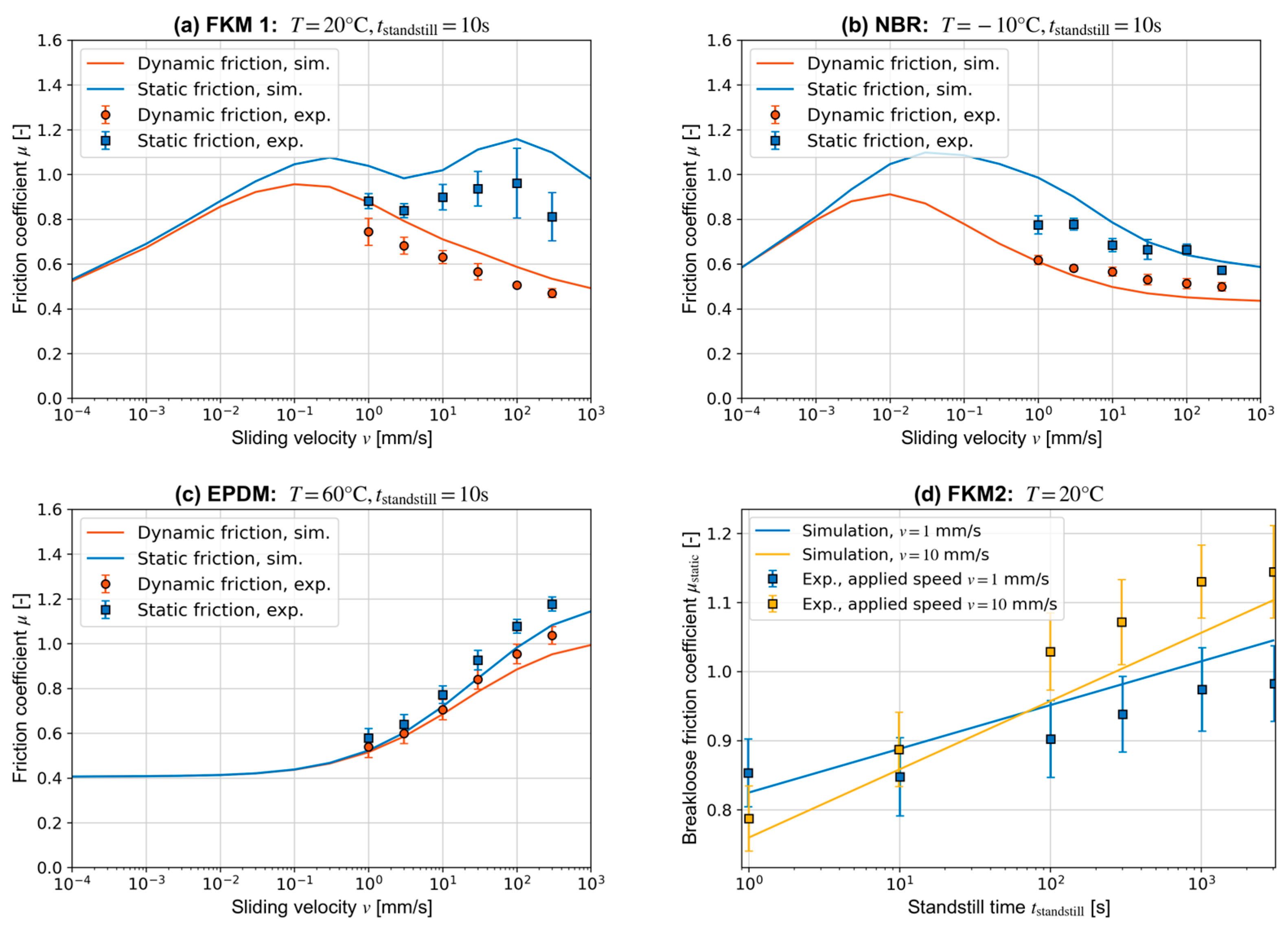
Furthermore, once the elastomer-dependent parameters k , c and ϵ have been determined for sliding conditions, the model can also be applied to quantify breakloose friction. Figure 6 shows how the static friction coefficient depends on the applied macroscopic sliding velocity (a–c) and standstill time (d). Additionally, in this case the simulations capture the main features of the experimental data, with a comparable accuracy to the dynamic friction model.

3.2. Relevance of Friction Contributions

In the development framework for new sealing product and rubbers, the validated dry friction model can be used to gain new insights on the tribological behavior of elastomers. First, one can study the system under conditions which are difficult to access experimentally, e.g., to quantify friction at very low or high sliding velocities, or for long standstill times of the order of days or weeks.
Furthermore, the model can be used to analyze which friction contributions are relevant under given tribological conditions, ultimately providing guidance on how to optimize a certain system, for instance, by tuning the elastomer properties or the surface finishing, to obtain a desired friction behavior. We discuss this aspect in the following, focusing on the operating conditions in temperature and sliding speed first.
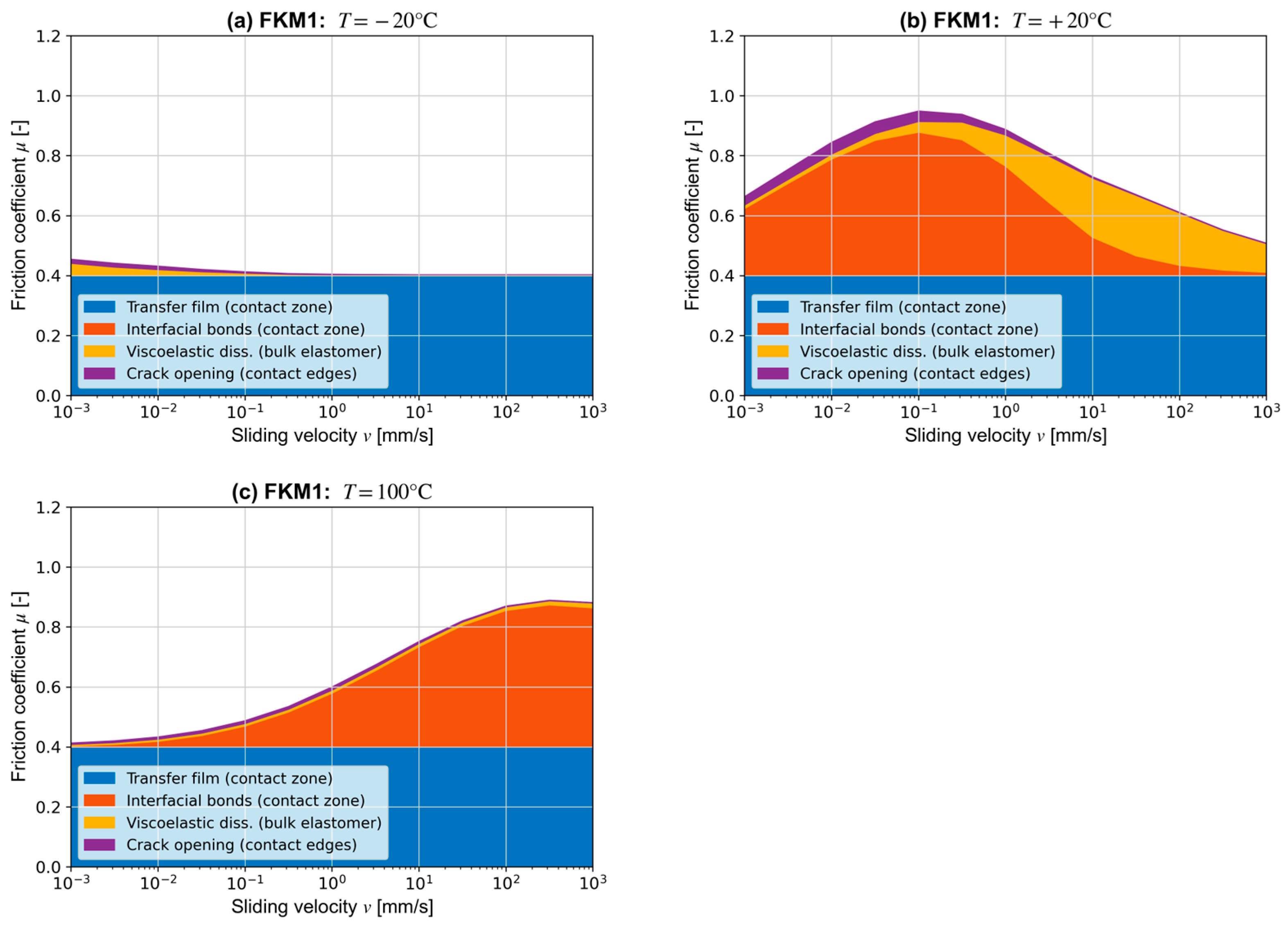
Figure 7a shows the simulated friction for FKM 1 at −20 °C, well below its glass transition temperature. As expected, the transfer film μ t r a n s f e r dominates the friction process, with the other terms vanishing at sliding speeds above 1 mm/s. At 20 °C (see Figure 7b), contact friction due to interfacial bonds and the transfer film is the most important contribution at sliding speeds of up to 10 mm/s, while at higher velocities the viscoelastic term also becomes significant. The contribution of crack opening at the asperity scale is small throughout the analyzed range of sliding speeds. Increasing the temperature to 100 °C (see Figure 7c) shifts the peak of all contributions to higher sliding velocities, in accordance with the shift factors a T for the interfacial bonds and a T for the viscoelastic friction. This results in μ c o n t a c t being the only relevant contribution in the considered velocity range. At even higher sliding speeds beyond 1 m/s, μ v i s c o e l a s t i c may also become significant, but the elastomer would heat up and fail rapidly in dry conditions, which makes this practically irrelevant for technical systems.
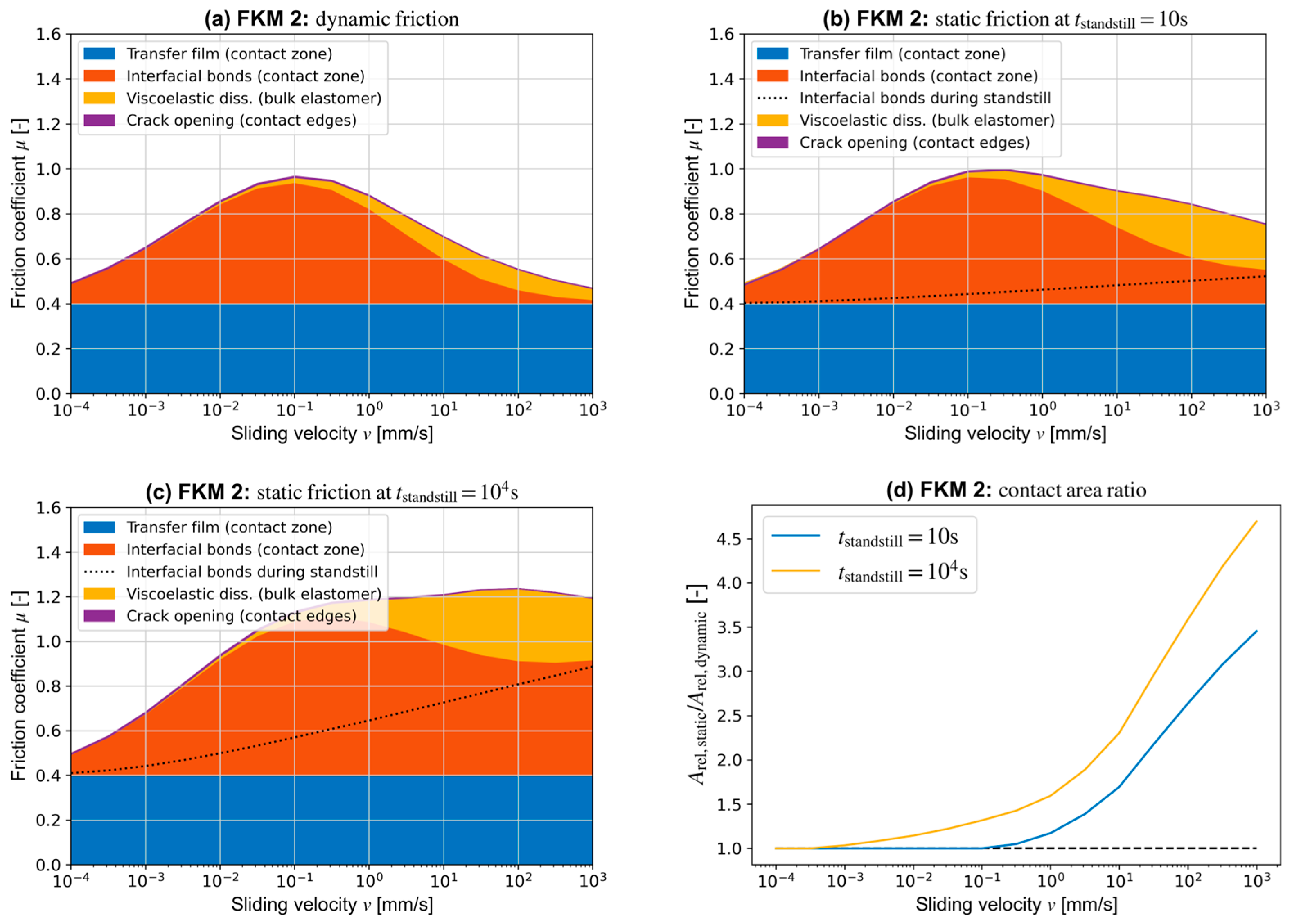
In Figure 8, dynamic friction for FKM 2 is compared to the contributions for breakloose friction at standstill times of a few seconds and a few hours. According to the proposed model, μ t r a n s f e r is unchanged, μ c r a c k remains negligible over the whole velocity range and the bonding and viscoelastic terms change significantly at applied speeds exceeding 1 mm/s. Both μ b o n d i n g and μ v i s c o l e a s t i c scale up with the contact area ratio A r e l , s t a t i c / A r e l , s l i d i n g . As shown in Figure 8d for the two considered standstill times, this quantity becomes significantly larger than unity for v > 10 mm/s, where FKM 2 at T = 20 °C showcases a glassy response under sliding and a rubbery behavior during standstill.
In this velocity range, the bonding friction contribution μ b o n d i n g decays rapidly under dynamic conditions, as the rate for bond formation is slow compared to the characteristic time of sliding. However, during standstill strong bonds can form with the counterface (see Section 2.2.3), which must be sheared during the breakloose process, causing increased friction. This additional contribution to the bonding term is visualized through the dotted line in Figure 8b,c. At standstill times of a few seconds or minutes, its impact on the total friction coefficient remains minor. However, it becomes significant at longer t s t a n d s t i l l periods, which allow more strong bonds to form at the interface over an increased contact area A r e l , s t a t i c .
Finally, the viscoelastic contribution also scales up with the ratio A r e l , s t a t i c / A r e l , s l i d i n g compared to dynamic friction, leading to a term of the same order of magnitude of the bonding friction contribution in the v > 1 0 mm/s velocity range. When summing all static friction contributions, a second peak can appear at high applied velocities in addition to the maximum of the bonding friction bell curve. This is, for instance, the case for FKM 1 at T = 20   °C seen in Figure 6a and for FKM 2 in Figure 8c.
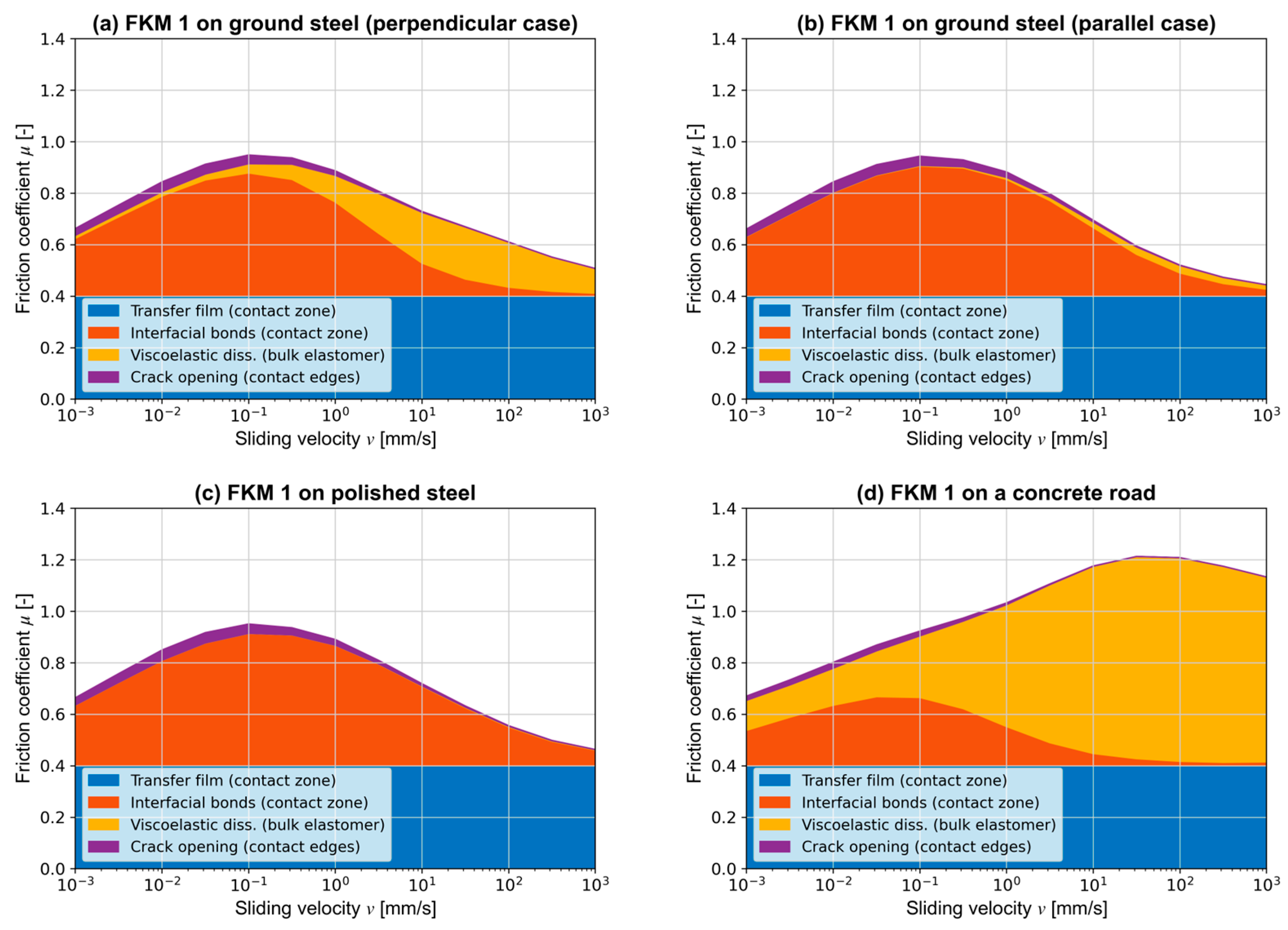
We now investigate how the dynamic friction contributions vary as a function of surface roughness. Up to now, the reference surface was the ground steel sample mentioned in Section 2.1.2, with the sliding direction set as perpendicular to the grinding pattern. The results are recalled in Figure 9a for reference. In Figure 9b, a similar ground surface is used, but this time the rubber slides along the surface “grooves”. While the overall friction coefficient stays approximately constant, two significant changes occur in the friction contributions. First, the viscoelastic term is strongly reduced as the pulsating excitations due to roughness and related energy losses in the rubber are suppressed. Second, the bonding friction contribution rises in the velocity range between 1 mm/s and 1 m/s. Here, in absence of a high frequency excitation, the elastomer showcases a rubbery response with a softer contact modulus, leading to an increased contact area and higher μ b o n d i n g . Similar trends can be observed when considering a polished counter surface: the viscoelastic term vanishes completely, leaving contact friction as the only contribution of the friction coefficient (Figure 9c).
Based on these results, it may seem surprising that Persson developed a model for viscoelastic rubber friction first [5], with the contact model following more than a decade later [30]. Other groups have also focused on the viscoelastic contribution [42]. It should be noted that most literature on dry rubber friction has mainly treated tire–road contacts. To understand what difference this makes in terms of friction contributions, we have performed simulations using data for a concrete road surface from [16], as seen in Figure 9d. Its root mean square roughness h r m s 141   μ m is about 300 times larger than the ground steel surfaces where h r m s 0.5   μ m . A comparison of several important surface metrics in Table 4 highlights the differences.
Between Figure 9a with Figure 9d, one can see important differences. First, the viscoelastic contribution is much bigger at all sliding speeds for the concrete road surface, leading to a significantly increased friction peak at approx. 50 mm/s where the viscoelastic losses in the elastomer are maximal. This is due to the larger dynamic excitation of the rubber bulk material during sliding through the increased roughness of the road countersurface. The latter also leads to a reduction in contact area A t r u e under the same given external load compared to the reference case of Figure 9a, so that the interfacial bond contribution becomes secondary for the total friction coefficient. Finally, in tire–road contacts, the rolling motion also leads to an increased crack opening contribution. This aspect is not considered in our model, which has been fine-tuned for the sliding motion typical of sealing applications.
Ultimately, it is crucial to ensure that any simulation model provides an adequate description for the system under study. Specifically for elastomer friction, when looking into tire contacts, μ v i s c o e l a s t i c is indeed a key contribution due to the large roughness of road surfaces. However, typical engineering surfaces used in sealing applications are orders of magnitude smoother, such that the contact friction contribution becomes dominant due to the increased contact area and the reduction of viscoelastic losses.

4. Summary and Conclusions

In this work, we present a physically based model for the static and dynamic friction of elastomers in dry conditions. For steady state sliding, we base our approach on the works of Persson and coworkers. The total friction coefficient is divided into several contributions, each representative of a separate friction process. Both interfacial bonding and shearing of a transfer film occur in the true contact area between the elastomer and counterface. Viscoelastic dissipation occurs in the elastomer bulk, while a crack opening process takes place at contact edges during sliding.
We then propose an extension of the model to treat static friction. Here, the friction contributions scale up with the increased contact area due to elastomer relaxation during standstill. Additionally, the interfacial bonding contribution is improved to account for creep motion in the breakloose phase, based on bond population models by Juvekar and coworkers.
After parameterization of only three elastomer-dependent constants, the model can predict friction for a given rubber–counterface contact at several applied speeds, temperatures or standstill times. The model is compared to tribological experiments, showing good accuracy over a wide range of conditions for four commercial rubber compounds with different base polymers.
For typical engineering surfaces used in sealing applications, the most important friction contribution comes from contact area between the rubber and counterface, i.e., from interfacial bonding and the transfer film. However, the relative importance of individual friction phenomena can change drastically depending on the roughness of the hard counterbody. When considering sliding over a road surface, viscoelastic friction increases significantly and becomes the dominant contribution.
From our perspective as a sealing and lubricant manufacturing company, this information is crucial to develop novel products and optimized elastomer formulations for customer applications, as the required changes will depend on the most relevant friction contributions in each specific case.
Accessing this knowledge is very difficult with traditional approaches based purely on experiments. The viscoelastic and bonding contributions, both bell-shaped curves with the sliding velocity, can differ significantly in terms of amplitude and width. These differences are large enough to change the frictional behavior, depending on the operating conditions. However, the two contributions overlap over a wide range of speeds and feature similar temperature shift factors, so it is impossible to accurately discern the two terms by looking at the total, i.e., experimental friction coefficient.
Conversely, the friction contributions in each tribological system can be quickly predicted in a quantitative way from the current simulation model for dry elastomer friction. This will constitute a powerful tool to speed up material and product development, allowing for better transferability between simple tribological tests and actual product operation, and providing crucial knowledge for elastomer optimization.
Finally, this model can also be used as a solid foundation to model lubricated conditions where dry contact can occur locally depending on the elastomer–fluid wetting properties [23].

Author Contributions

Conceptualization, F.K. and D.S.; methodology, F.K. and D.S.; software, F.K. and D.S.; validation, F.K.; writing—original draft preparation, D.S. and F.K.; writing—review and editing, F.K., D.S. and R.B.; visualization, F.K. and D.S.; supervision, R.B.; project administration, F.K. and R.B.; funding acquisition, F.K. and R.B. All authors have read and agreed to the published version of the manuscript.

Funding

This research received no external funding.

Data Availability Statement

Some data presented in this article are not readily available for confidentiality reasons. Requests to access the datasets should be directed to F.K.

Acknowledgments

We would like to thank Michele Scaraggi for the fruitful discussions regarding theory development and implementation. The authors would also like to thank Freudenberg for permission to publish this work for the 175th anniversary of the company.

Conflicts of Interest

The test specimens examined in this study are the property of Freudenberg Technology Innovation SE & Co. KG. The authors are employees of Freudenberg Technology Innovation SE & Co. KG. The results were obtained in the course of their work.

References

  1. Kammüller, M. Zum Abdichtverhalten von Radial-Wellendichtringen. Ph.D. Thesis, University of Stuttgart, Stuttgart, Germany, 1986. [Google Scholar]
  2. Müller, H.K.; Nau, B. Fluid Sealing Technology; Marcel Dekker: New York, NY, USA, 1998. [Google Scholar]
  3. Greenwood, J.A.; Williamson, J.B.P. Contact of Nominally Flat Surfaces. Proc. R. Soc. A Math. Phys. Eng. Sci. 1966, 295, 300–319. [Google Scholar]
  4. Persson, B.N.J. Theory of powdery rubber wear. J. Phys. Condens. Matter 2009, 21, 485001. [Google Scholar] [CrossRef] [PubMed]
  5. Persson, B.N.J. Theory of rubber friction and contact mechanics. J. Chem. Phys. 2001, 115, 3840–3861. [Google Scholar] [CrossRef]
  6. Müser, M.H.; Dapp, W.B.; Bugnicourt, R.; Sainsot, P.; Lesaffre, N.; Lubrecht, T.A.; Persson, B.N.J.; Harris, K.; Bennett, A.; Schulze, K.; et al. Meeting the Contact-Mechanics Challenge. Tribol. Lett. 2017, 65, 118. [Google Scholar] [CrossRef]
  7. Persson, B.N.J.; Scaraggi, M. Theory of adhesion: Role of surface roughness. J. Chem. Phys. 2014, 141, 124701. [Google Scholar] [CrossRef] [PubMed]
  8. Persson, B.N.J. Contact mechanics for layered materials with randomly rough surfaces. J. Phys. Condens. Matter 2012, 24, 095008. [Google Scholar] [CrossRef] [PubMed]
  9. Persson, B.N.J. Contact mechanics for randomly rough surfaces. Surf. Sci. Rep. 2006, 61, 201–227. [Google Scholar] [CrossRef]
  10. Persson, B.N.J.; Yang, C. Theory of the leak-rate of seals. J. Phys. Condens. Matter 2008, 20, 315011. [Google Scholar] [CrossRef]
  11. Tiwari, A.; Persson, B.N.J. Physics of suction cups. Soft Matter 2019, 15, 9482–9499. [Google Scholar] [CrossRef]
  12. Persson, B.N.J. Fluid Leakage in Static Rubber Seals. Tribol. Lett. 2022, 70, 31. [Google Scholar] [CrossRef]
  13. Fischer, F.J.; Schmitz, K.; Tiwari, A.; Persson, B.N.J. Fluid Leakage in Metallic Seals. Tribol. Lett. 2020, 68, 125. [Google Scholar] [CrossRef]
  14. Pérez-Ràfols, F.; Larsson, R.; Almqvist, A. Modelling of leakage on metal-to-metal seals. Tribol. Int. 2016, 94, 421–427. [Google Scholar] [CrossRef]
  15. Jin, L.; Cheng, Y.; Zhang, K.; Xue, Z.; Liu, J. Axisymmetric model of the sealing cylinder in service: Analytical solutions. J. Mech. 2021, 37, 404–414. [Google Scholar] [CrossRef]
  16. Tiwari, A.; Miyashita, N.; Espallargas, N.; Persson, B.N.J. Rubber friction: The contribution from the area of real contact. J. Chem. Phys. 2018, 148, 224701. [Google Scholar] [CrossRef]
  17. Tolpekina, T.V.; Persson, B.N.J. Adhesion and Friction for Three Tire Tread Compounds. Lubricants 2019, 7, 20. [Google Scholar] [CrossRef]
  18. Wohlers, A.; Heipl, O.; Persson, B.N.J.; Scaraggi, M.; Murrenhoff, H. Numerical and Experimental Investigation on O-Ring-Seals in Dynamic Applications. Int. J. Fluid Power 2009, 10, 51–59. [Google Scholar] [CrossRef]
  19. Dowson, D. History of Tribology; Wiley: Hoboken, NJ, USA, 1998. [Google Scholar]
  20. Almqvist, A. On the Effects of Surface Roughness in Lubrication. Ph.D. Thesis, Luleå University of Technology, Luleå, Sweden, 2006. [Google Scholar]
  21. Persson, B.N.J.; Scaraggi, M. Lubricated sliding dynamics: Flow factors and Stribeck curve. Eur. Phys. J. E 2011, 34, 113. [Google Scholar] [CrossRef] [PubMed]
  22. Bongaerts, J.H.H.; Foutouni, K.; Stokes, J.R. Soft-tribology: Lubrication in a compliant PDMS–PDMS contact. Tribol. Int. 2007, 40, 1531–1542. [Google Scholar] [CrossRef]
  23. Persson, B.N.J.; Mugele, F. Squeeze-out and wear: Fundamental principles and applications. J. Phys. Condens. Matter 2004, 16, 295–355. [Google Scholar] [CrossRef]
  24. Martin, A.; Clain, J.; Burguin, A.; Brochard-Wyart, F. Wetting transitions at soft, sliding interfaces. Phys. Rev. E 2002, 63, 031605. [Google Scholar] [CrossRef]
  25. Williams, M.L.; Landel, R.F.; Ferry, J.D. The Temperature Dependence of Relaxation Mechanisms in Amorphous Polymers and Other Glass-forming Liquids. J. Am. Chem. Soc. 1955, 77, 3701–3707. [Google Scholar] [CrossRef]
  26. Jacobs, T.B.; Junge, T.; Pastewka, L. Quantitative characterization of surface topography using spectral analysis. Surf. Topogr. Metrol. Prop. 2017, 5, 13001. [Google Scholar] [CrossRef]
  27. Persson, B.N.J.; Albohr, O.; Tartaglino, U.; Volokitin, A.I.; Tosatti, E. On the nature of surface roughness with application to contact mechanics, sealing, rubber friction and adhesion. J. Phys. Condens. Matter 2005, 17, R1. [Google Scholar] [CrossRef]
  28. Yang, C.; Persson, B.N.J. Contact mechanics: Contact area and interfacial separation from small contact to full contact. J. Phys. Condens. Matter 2008, 20, 215214. [Google Scholar] [CrossRef]
  29. Wang, A.; Müser, M.H. Gauging Persson Theory on Adhesion. Tribol. Lett. 2017, 65, 103. [Google Scholar] [CrossRef]
  30. Lorenz, B.; Oh, Y.R.; Nam, S.K.; Jeon, S.H.; Persson, B.N.J. Rubber friction on road surfaces: Experiment and theory for low sliding speeds. J. Chem. Phys. 2015, 142, 194701. [Google Scholar] [CrossRef]
  31. Singh, A.K.; Juvekar, V.A. Steady dynamic friction at elastomer–hard solid interface: A model based on population balance of bonds. Soft Matter 2011, 7, 10601–10611. [Google Scholar] [CrossRef]
  32. Fortunato, G.; Ciaravola, V.; Furno, A.; Lorenz, B.; Persson, B.N.J. General Theory of frictional heating with application to rubber friction. J. Phys. Condens. Matter 2015, 27, 175008. [Google Scholar] [CrossRef]
  33. Persson, B.N.J. Rubber friction: Role of the flash temperature. J. Phys. Condens. Matter 2006, 18, 7789–7823. [Google Scholar] [CrossRef]
  34. Persson, B.N.J. Crack propagation in finite-sized viscoelastic solids with application to adhesion. Europhys. Lett. 2017, 119, 18002. [Google Scholar] [CrossRef]
  35. Tiwari, A.; Dorogin, L.; Tahir, M.; Stöckelhuber, K.W.; Heinrich, G.; Espallargas, N.; Persson, B.N.J. Rubber contact mechanics: Adhesion, friction and leakage of seals. Soft Matter 2017, 13, 9103–9121. [Google Scholar] [CrossRef] [PubMed]
  36. Lengiewicz, J.; de Souza, M.; Lahmar, M.A.; Courbon, C.; Dalmas, D.; Stupkiewicz, S.; Scheibert, J. Finite deformations govern the anisotropic shear-induced area reduction of soft elastic contacts. J. Mech. Phys. Solids 2020, 143, 104056. [Google Scholar] [CrossRef]
  37. Lorenz, B.; Persson, B.N.J. On the origin of why static or breakloose friction is larger than kinetic friction, and how to reduce it: The role of aging, elasticity and sequential interfacial slip. J. Phys. Condens. Matter 2012, 24, 225008. [Google Scholar] [CrossRef] [PubMed]
  38. Maegawa, S.; Itoigawa, F.; Nakamura, T. New insight into the mechanism of static friction: A theoretical prediction of the effect of loading history on static friction force based on the static friction model proposed by Lorenz and Persson. Tribol. Int. 2016, 102, 532–539. [Google Scholar] [CrossRef]
  39. Soni, P.; Singh, A.; Katiyar, J. Experiments and Prediction of Hold Time-Dependent Static Friction of a Wet Granular Layer. Tribol. Lett. 2023, 71, 75. [Google Scholar] [CrossRef]
  40. Creton, C.; Ciccotti, M. Fracture and adhesion of soft materials: A review. Rep. Prog. Phys. 2016, 79, 046601. [Google Scholar] [CrossRef]
  41. Müser, M.H.; Persson, B.N.J. Crack and pull-off dynamics of adhesive, viscoelastic solids. Europhys. Lett. 2022, 137, 36004. [Google Scholar] [CrossRef]
  42. Le Gal, A.; Klüppel, M. Investigation and modelling of rubber stationary friction on rough surfaces. J. Phys. Condens. Matter 2008, 20, 015007. [Google Scholar] [CrossRef]
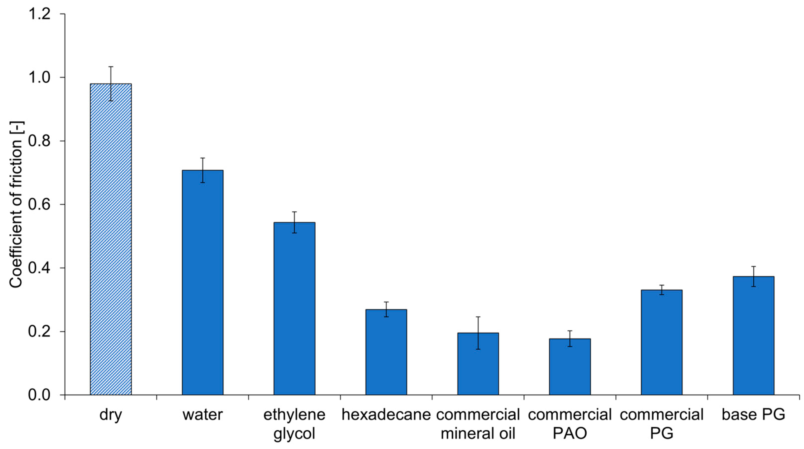
Figure 1. Boundary friction coefficient for FKM 1 with simple fluids and commercial oils (PAO = polyalphaolefine, PG = polyglycol).
Lubricants 12 00250 g001
Figure 2. Master curves of the shear moduli G′, G″ and the loss tangent tan(δ) as a function of excitation frequency for FKM 1 at 20 °C.
Lubricants 12 00250 g002
Figure 3. Roughness topography of (a) the ground counterface and (b) worn rubber. (c) Directional and angular average PSDs of the ground steel counterface. A polished surface is also shown for comparison purposes. (d) PSDs of worn rubber surfaces (gray) and their average (black).
Lubricants 12 00250 g003
Figure 4. Schematic illustration of test setup.
Lubricants 12 00250 g004
Figure 5. Comparison of the dry dynamic elastomer friction model with experimental data: (a) FKM 1, (b) FKM 2, (c) NBR and (d) EPDM.
Lubricants 12 00250 g005
Figure 6. Comparison of the elastomer friction model with experimental data: (ac) Dependence of dynamic and breakloose friction on the applied sliding velocity in the experiment. (d) Dependence of static friction on standstill time, for two given sliding velocities.
Lubricants 12 00250 g006
Figure 7. Dynamic friction contributions for FKM1 at different temperatures: (a) −20 °C, (b) 20 °C and (c) 100 °C.
Lubricants 12 00250 g007
Figure 8. (a) Dynamic friction contributions for FKM 2 at 20 °C. (b,c) Static friction contributions under the same conditions for two different standstill times. (d) Ratio of contact areas A r e l , s t a t i c / A r e l , s l i d i n g as a function of the applied velocity v .
Lubricants 12 00250 g008
Figure 9. Dynamic friction contributions for FKM 1 sliding over different countersurfaces at 20 °C, with their main surface metrics listed in Table 4. (a) Standard configuration with a ground steel surface. Here, the sliding direction is perpendicular to the roughness pattern of the metal counterface. (b) A similar ground steel surface, with sliding occurring parallel to the roughness pattern. (c) Polished steel surface. (d) Concrete road surface.
Lubricants 12 00250 g009
Table 1. Overview of the elastomer materials. The reported glass transition temperature T g was obtained from Dynamic Mechanical Analysis performed at 0.1 Hz.
MaterialTypical
Application
ColorCross-LinkerFillersShore
Hardness
T g (°C)
FKM 1Radial
shaft seals
Red–brownBisphenolicMineral75−8 °C
FKM 2O-ringsDark
brown
BisphenolicMineral90−6 °C
NBRRadial
shaft seals
BlueSulphuricMineral75−20 °C
EPDMO-ringsBlackPeroxidicCarbon black75−44 °C
Table 2. Test conditions.
ParametersConditions
Stroke50 mm
Sliding Speeds1–300 mm/s
Waiting Times Between Strokes1–3600 s
Temperatures−40–100 °C (80 °C for NBR)
Normal Load40 N (approx. 1.3 MPa nominal contact pressure)
Table 3. Friction model parameters of Equations (5)–(7) and Equations (8) and (9) for the four elastomer materials. Here, k ,   c and ϵ are determined from the friction experiments in Section 3.1, while u and τ * are calculated from Equation (10).
Materialk [-]c [-] ϵ   [ e V ] u [-] τ * [-]
FKM 12.20.160.893.35 × 10−43.06
FKM 22.00.190.899.12 × 10−42.62
NBR2.80.291.16.73 × 10−31.78
EPDM1.70.190.779.12 × 10−42.62
Table 4. Metrics for different countersurfaces: The root mean square roughness height hrms and slope h’rms are defined in [12]. U e l / A 0   is the elastic energy per unit area to form full contact, calculated according to [9] with a representative contact modulus E * = 13.3 MPa.
Surfacehrms [µm] U e l / A 0 [J/m2] h’rms [-]
Ground steel (perpendicular case)0.470.250.28
Ground steel (parallel case)0.480.190.18
Polished steel0.0590.00710.049
Concrete road1412471.22
Disclaimer/Publisher’s Note: The statements, opinions and data contained in all publications are solely those of the individual author(s) and contributor(s) and not of MDPI and/or the editor(s). MDPI and/or the editor(s) disclaim responsibility for any injury to people or property resulting from any ideas, methods, instructions or products referred to in the content.