Article

Theoretical Evaluation of Lubrication Performance of Thrust-Type Foil Bearings in Liquid Nitrogen

by
Hang Dou
1,
Tao Jiang
1,
Longgui He
1,
Shuo Cheng
1,
Xiaoliang Fang
1,2 and
Jimin Xu
1,*
1
Institute of Tribology, School of Mechanical Engineering, Hefei University of Technology, Hefei 230009, China
2
Anhui Province Key Laboratory of Critical Friction Pair for Advanced Equipment, Hefei 230088, China
*
Author to whom correspondence should be addressed.
Lubricants 2024, 12(7), 257; https://doi.org/10.3390/lubricants12070257
Submission received: 12 June 2024 / Revised: 8 July 2024 / Accepted: 15 July 2024 / Published: 17 July 2024
(This article belongs to the Special Issue Aerospace Tribology)

Abstract

:
The development of reusable liquid rocket turbopumps has gradually highlighted the disadvantages of rolling bearings, particularly the contradiction between long service life and high rotational speed. It is critical to explore a feasible bearing scheme offering a long wear life and high stability to replace the existing rolling bearings. In this study, liquid nitrogen is adopted to simulate the ultra-low temperature environment of liquid rocket turbopumps, and theoretical evaluations of the lubrication performance of thrust-type foil bearings in liquid nitrogen are conducted. A link-spring model for the bump foil structure and a thin-plate finite element model for the top foil structure are established. The static and dynamic characteristics of the bearings are analyzed using methods including the finite difference method, the Newton–Raphson iteration method, and the finite element method. Detailed analysis includes the effects of factors such as rotational speed, fluid film thickness, thrust disk tilt angle, and the friction coefficient of the bump foil interface on the static and dynamic characteristics of thrust-type foil bearings. The research results indicate that thrust-type foil bearings have a good load-carrying capacity and low frictional power consumption. The adaptive deformation of the foil structure increases the fluid film thickness, preventing dry friction due to direct contact between the rotor journal and the bearing surface. When faced with thrust disk tilt, the direct translational stiffness and damping coefficient of the bearing do not undergo significant changes, ensuring system stability. Based on the results of this study, the exceptional performance characteristics of thrust-type foil bearings make them a promising alternative to rolling bearings for the development of reusable liquid rocket turbopumps.

1. Introduction

The recovery and reutilization of liquid-propellant rockets can significantly reduce the launch costs and play a critical role in promoting large-scale high-frequency space activities [1,2]. Whether the high-speed turbopumps, the heart of liquid rockets, can truly achieve maintenance-free reutilization determines the actual launch cost [3]. For example, NASA (National Aeronautics and Space Administration) initially aimed to control the cost of the space shuttle to be under 30 million dollars per launch. However, due to the long and complicated maintenance of the liquid rocket turbopumps, the actual cost per launch reached as high as 500 million dollars [4]. To date, all launched liquid-propellant rocket turbopumps have utilized rolling element bearings to support their high-speed shaft systems, which transmit external loads via point or line contacting form [5,6]. Due to the limitation of wear resistance, it is challenging to achieve a long service life for rolling bearings under high rotational speeds. The reported maximum DN (the product of inner diameter D and rotational speed N) value of rolling bearings in rocket turbopumps is around 3 × 106 mm·r·min−1 [7]. To overcome the contradiction between long service life and high rotational speed in rolling bearings, major space powers have explored the application feasibility of fluid film bearings to improve high-speed performance. The pressurized film inside fluid film bearings, usually generated by hydrodynamic or hydrostatic effect, separates the rotor journal from the bearing surface, which can significantly decrease the wear degree [8,9,10,11,12]. As early as 1983, Hanum et al. [13] from NASA designed a combination bearing system with two angular contact rolling bearings and a hydrostatic bearing. They tested the combination bearing in the MK48 turbopump rotor system and found that the wear inside the rolling bearings was slight even after 2337 start-ups and running at a maximum rotational speed of 70,000 r·min−1. The introduction of hydrostatic fluid film bearings could significantly extend the wear life of rolling bearings. Since then, researchers have begun exploring the feasibility of completely abandoning rolling bearings and using fluid film bearings only. Ohta et al. [14] designed and tested a hydrostatic bearing with ten cavities for LE-5 LH2 (liquid hydrogen) turbopumps. The inner diameter of the bearing is 52.1 mm and the average radial clearance is 50 μm. During the start-up stage, the rotor journal could separate from the bearing surface through the hydrostatic pressure of LH2. When the rotational speed reached 50,000 r·min−1 and the supply of high-pressure liquid hydrogen was stopped, the rotor can also achieve a stable running state through the generated hydrodynamic pressure. Around 2010, the French national space agency and the Swedish national space board implemented the TPX full-size LH2 turbopump demonstration program, employing hydrostatic fluid film bearings for frequent tests [15]. The maximum tested rotational speed was 39,500 r·min−1.
However, the severe friction and wear during the start-up and stopping stages of hydrodynamic fluid film bearings cannot be ignored, and it is almost impossible to add a high-pressure fluid source into rocket turbopumps for hydrostatic fluid film bearings [16]. Therefore, new bearing schemes have been proposed and investigated successively. Xu et al. [17] proposed the scheme of superconducting compound bearings, which combine a superconducting magnetic field and a hydrodynamic fluid field, for reusable rocket turbopumps. The superconducting compound bearings can simultaneously ensure friction-free operation during the start-up and stopping stages through the superconducting magnetic field, and provide high stability during the steady working stage through the hydrodynamic fluid field [18]. In particular, due to the outstanding reliability of gas foil bearings in turbomachinery, NASA evaluated the performance of foil bearings in cryogenic fluids and their feasibility for rocket application [19]. The mean time between failures of gas foil bearings in aircraft turbo-compressors can exceed 60,000 h [20]. Demonstration experiments of foil bearings in LH2 and LO2 (liquid oxygen) rocket turbopumps [21] were successfully conducted in 1992 and 1993, respectively. The maximum test speeds reached 91,000 r·min−1 and 25,000 r·min−1, respectively. After over 100 start-up/stopping cycles, the wear of the foil bearings was acceptable for continuing experiments.
Generally, existing theoretical investigations on foil bearings, including journal and thrust-type bearings, primarily focus on the operating environment of gas lubrication. Since thrust-type foil bearings are required to accommodate variations in axial loads, it is critical to understand the interaction mechanism between the journal and the bearing surface [22]. Shi et al. [23] established an analytical model of aerostatic thrust bearing with three degrees of freedom (DOFs), considering interaction among perturbation Reynolds equations related to stiffness and damping. Xu et al. [24] proposed a comprehensive model of gas foil thrust bearings combining isoparametric elements with contact mechanics, which enables the analysis of arbitrarily shaped foils. Chen et al. [25] developed a dynamic model of a foil thrust bearing with an angular swing pad, and the influence of angular disturbance on the load-carrying capacity was analyzed. Feng et al. [26] employed a link-spring structural model to calculate the equivalent vertical stiffness of bump-type gas foil thrust bearings. For engineering applications, it is important to ensure the load capacity of thrust-type foil bearings. Somaya et al. [27] evaluated the performance of an aerodynamic foil thrust bearing at a high rotational speed of 350,000 r·min−1, and the load capacity coefficient was improved to 5.36 × 10⁻⁶ N/(mm3·kr·min−1). In addition to the increase in the operational speed, structural modifications are frequently adopted to enhance the load capacity, including the hybrid bearing combining an air foil bearing and a hydrostatic air bearing [28], a multi-layer foil structure [29,30,31], and a Ryleigh step air foil structure [32]. These investigations provide a solid theoretical foundation for analyzing thrust-type foil bearings under various lubrication conditions.
In this study, with prospects for application in liquid rocket turbopumps, theoretical evaluations of the lubrication performance of thrust-type foil bearings in liquid nitrogen were conducted. Liquid nitrogen was chosen to simulate cryogenic fluid in rocket turbopumps for safety, and further experimental verifications in the lab were relatively easy to perform. The static and dynamic characteristics of thrust-type bearings in liquid nitrogen were analyzed and the application feasibility in rocket turbopumps were discussed.

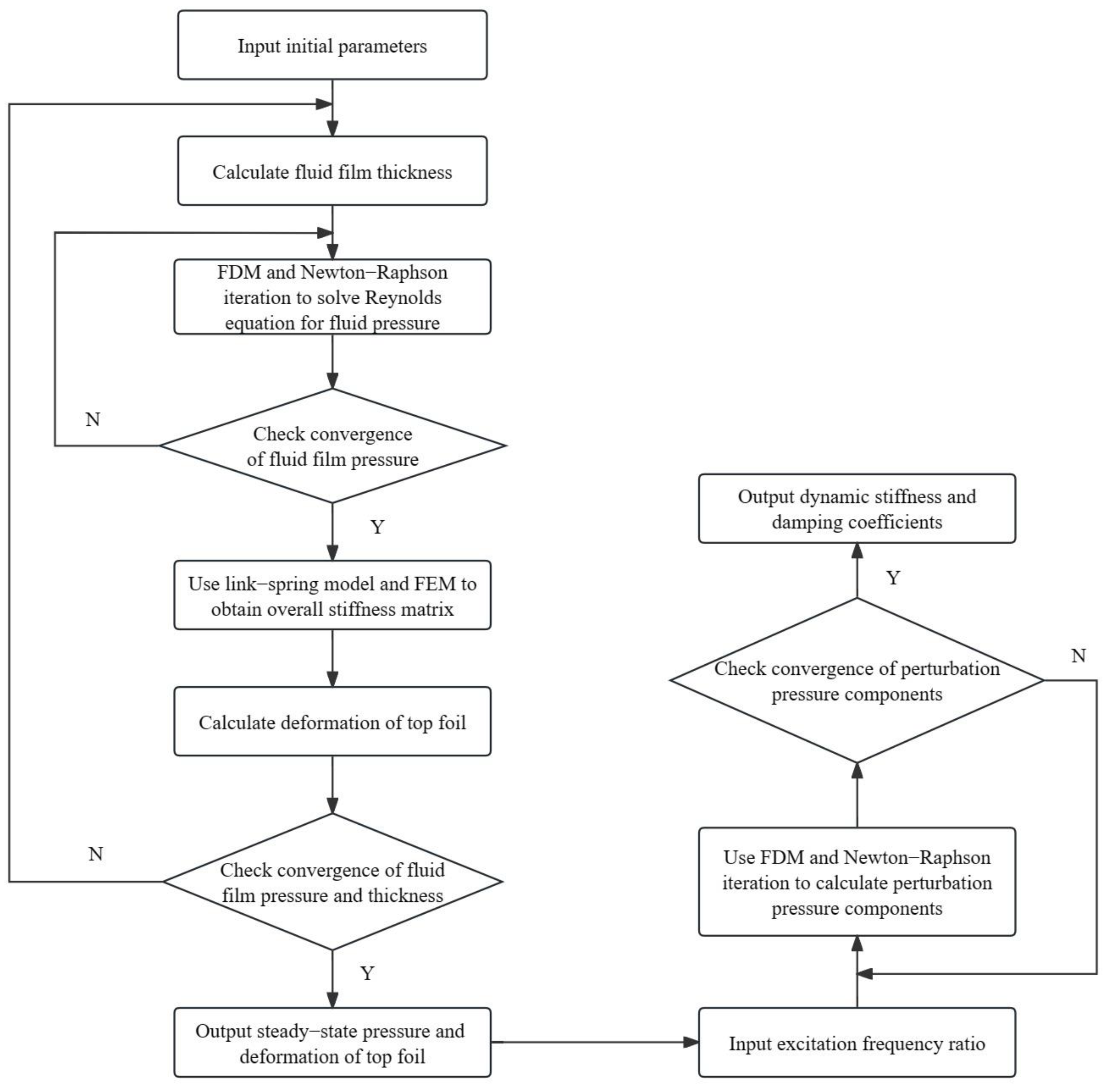
2. Theoretical Analysis Procedures

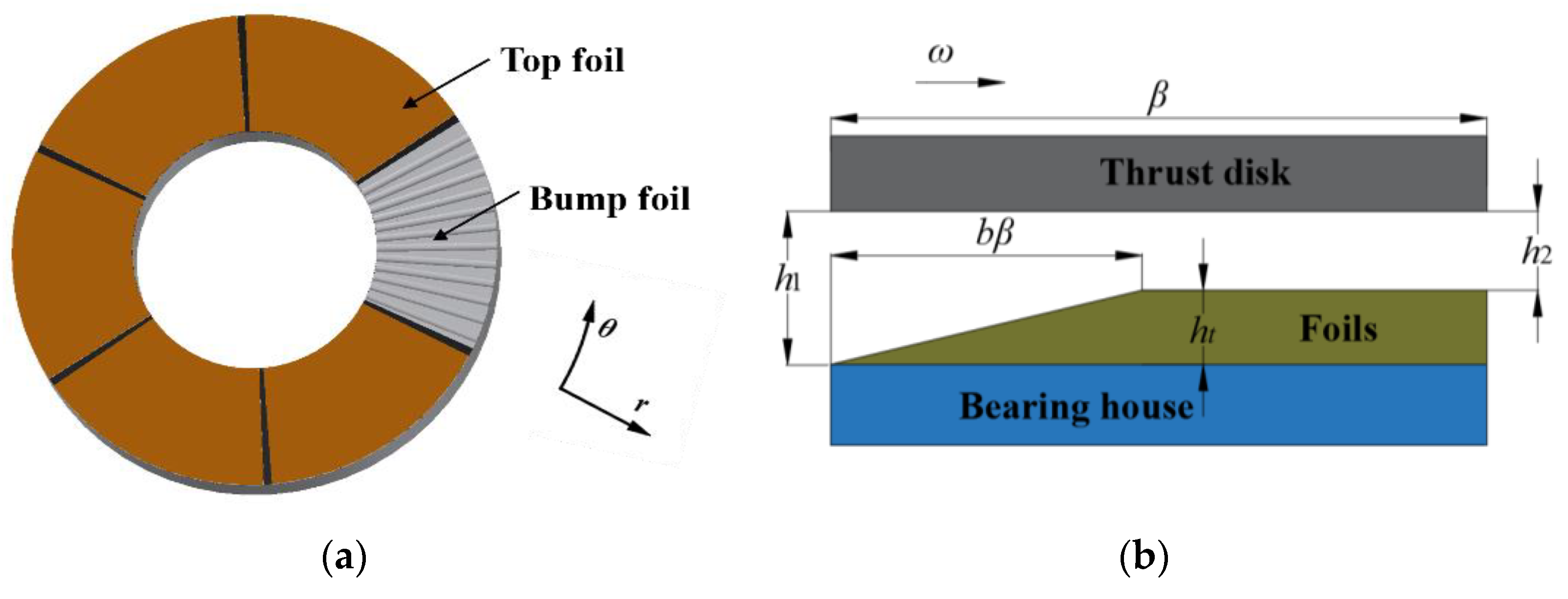
2.1. Fluid Lubrication Equations

The mass density of liquid nitrogen is around 808 kg·m−3 and it can maintain fluid state at low temperatures or high pressure. In this study, the supply pressure of liquid nitrogen is 1 MPa and the evaporation of liquid nitrogen can be ignored. Therefore, liquid nitrogen can be regarded as incompressible fluid. Figure 1 illustrates the schematic diagram of the thrust-type foil bearing, and a cylindrical coordinate system is introduced for modeling. The derivation from the Navier–Stokes equations to the Reynolds equation is complex but well-developed. On the basis of the continuity equation and the Navier–Stokes equation [33], the dimensionless form of the 2D (two-dimensional) incompressible Reynolds equation applicable to foil thrust-type bearings is as follows:
1 r ¯ r ¯ r ¯ H 3 P r ¯ + 1 r ¯ 2 θ H 3 P θ = Λ H θ + 2 Λ γ H t ¯ H = h h 2 ,   r ¯ = r r 2 , P = p p s ,   t ¯ = w e t ,   Λ = 6 μ 0 ω P s r 2 h 2 2 ,   γ = ω e ω
where h 2 represents the initial minimum fluid film thickness, r 2 represents the outer radius of the thrust pad, H represents the dimensionless fluid film thickness, θ represents the circumferential coordinate, r ¯ represents the dimensionless axial coordinate, p s represents the supply pressure of liquid nitrogen, μ 0 represents the dynamic viscosity, ω e represents the external excitation frequency, and γ represents the ratio of external excitation frequency to shaft rotational frequency.
During actual assembly, rotor eccentricity cannot be completely avoided in rotating machinery. Such eccentricity changes the distance between the surface of the thrust-type foil bearing and the thrust disk, as shown in Figure 2. The thrust pads are numbered counterclockwise, and due to the inclination of the thrust disk relative to the bearing, the initial fluid film thickness distribution on different thrust pads becomes uneven. This uneven distribution affects the performance of the thrust-type foil bearing. Therefore, it is necessary to consider the impact of rotor misalignment on the performance of foil journal bearings.
The fluid film thickness of a thrust-type foil bearing consists of the initial gap between the rotor surface and the thrust disk surface h 2 + g   r , θ , the rotor misalignment gap h φ   r , θ , and the deformation of the bearing surface δ   r , θ . Using the cylindrical coordinate system shown in Figure 1, the dimensionless expression for fluid film thickness, considering foil deformation and rotor misalignment, can be derived as follows [34]:
H = 1 + g ¯ r ¯ , θ + δ ¯ r ¯ , θ + h ¯ φ r ¯ , θ
The initial wedge gap is as follows:
g ¯   r ¯ , θ = h 1 h 2 1 1 θ b β 0 < θ < b β 0 b β < θ < β
The gap produced by the rotor misalignment is as follows:
h ¯ φ   r ¯ , θ = r 2 φ ¯ y r ¯ cos θ φ ¯ x r ¯ sin θ φ ¯ x = φ x h 2   ;   φ ¯ y = φ y h 2

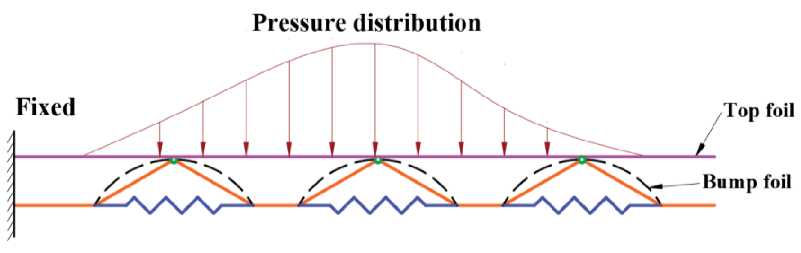
2.2. Foil Deformation Equation

To consider the effect of the top foil’s deformation on bearing performance, each bump foil is simplified into a link-spring model [35] consisting of two rigid links and a horizontal spring, as shown in Figure 3. This model fully accounts for the interaction forces between neighboring bump foils and the frictional forces at the contact surfaces, providing a comprehensive simulation of the actual working state of the bump foils. Since the top foil has a small thickness, a 3D (three-dimensional) finite element model of thin plate is established, considering both bending and shear stiffness. Each bump foil is equivalent to a spring, and the total stiffness matrix k f is obtained by combining the equivalent vertical stiffness k v of each bump foil calculated by the link-spring model and the stiffness matrix k t of the top foil calculated by the finite element method at the corresponding nodes.
The deformation of the top foil can be calculated using the direct stiffness method as k f U = F . U = δ 1 , θ x 1 , θ y 1 , , δ i , θ x i , θ y i , T represents the total displacement vector. F = P 1 , 0 , 0 , , P i , 0 , 0 , T represents the fluid film pressure vector. δ i is the deformation of the foil. θ x i and θ y i are the rotation angles about the X and Y axes.

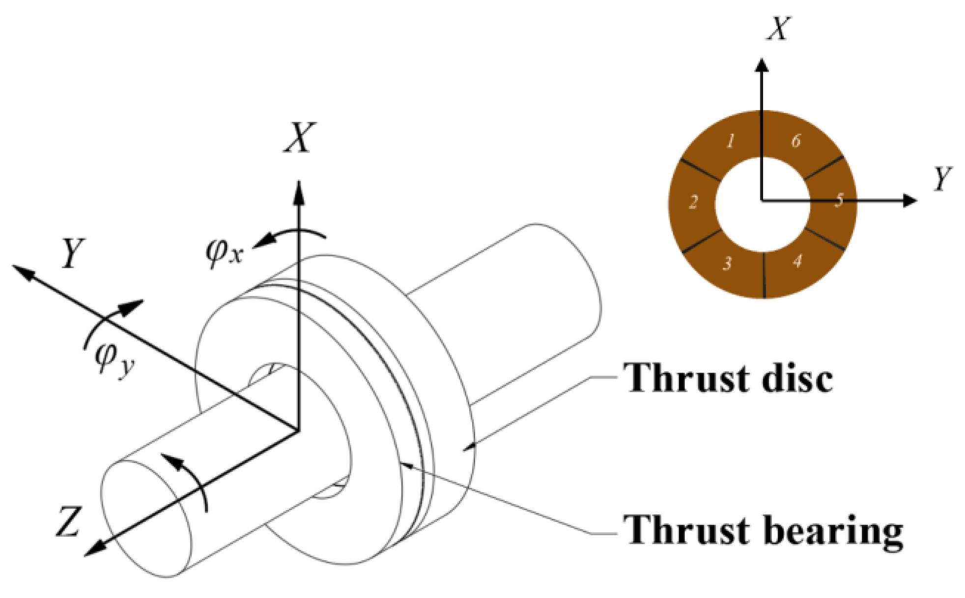
2.3. Calculation of Dynamic Characteristics

Given a displacement and velocity disturbance Δ z ¯ , Δ z ˙ ¯ , Δ φ ¯ x , Δ φ ˙ ¯ x , Δ φ ¯ y , Δ φ ˙ ¯ y in the axial direction of the thrust disk, the fluid film pressure P, fluid film thickness H, and foil deformation δ ¯ are expanded in a first-order Taylor series about the equilibrium position Δ z ¯ , Δ z ˙ ¯ , Δ φ ¯ x , Δ φ ˙ ¯ x , Δ φ ¯ y , Δ φ ˙ ¯ y , as follows:
P = P 0 + P z Δ z ¯ + P z ˙ Δ z ˙ ¯ + P φ x Δ φ ¯ x + P φ ˙ x Δ φ ˙ ¯ x + P φ y Δ φ ¯ y + P φ ˙ y Δ φ ˙ ¯ y H = H 0 + H z Δ z ¯ + H z ˙ Δ z ˙ ¯ + H φ x Δ φ ¯ x + H φ ˙ x Δ φ ˙ ¯ x + H φ y Δ φ ¯ y + H φ ˙ y Δ φ ˙ ¯ y δ ¯ = δ ¯ 0 + δ ¯ z Δ z ¯ + δ ¯ z ˙ Δ z ˙ ¯ + δ ¯ φ x Δ φ ¯ x + δ ¯ φ ˙ x Δ φ ˙ ¯ x + δ ¯ φ y Δ φ ¯ y + δ ¯ φ ˙ y Δ φ ˙ ¯ y
When the rotor undergoes small movements near the equilibrium position, the distribution of disturbed fluid film pressure can be obtained as follows:
H = H 0 + Δ z ¯ + r 2 Δ φ ¯ y Δ r ¯ cos θ Δ φ ¯ x Δ r ¯ sin θ + Δ δ ¯ H 0 = 1 + g ¯ + r 2 φ ¯ y Δ r ¯ cos θ φ ¯ x Δ r ¯ sin θ + δ ¯ 0 Δ δ ¯ = δ ¯ z Δ z ¯ + δ ¯ φ x Δ φ ¯ x + δ ¯ φ y Δ φ ¯ y
The disturbance of top foil’s deformation δ ¯ z , δ ¯ z ˙ , δ ¯ φ x , δ ¯ φ ˙ x , δ ¯ φ y , δ ¯ φ ˙ y can be obtained using the direct stiffness method, as follows:
  δ ¯ ζ ˙ = P ζ ˙ / k f ζ = z , φ x , φ y
where k f represents the total stiffness matrix of foil deformation. The equation for calculating the disturbed fluid film distribution can be obtained by combining the above equations, as follows:
H z = 1 + δ ¯ z H φ x = r 2 r ¯ sin θ + δ ¯ φ x H φ y = r 2 r ¯ cos θ + δ ¯ φ y H z ˙ H φ ˙ x H φ ˙ y T = δ ¯ z ˙ δ ¯ φ ˙ x δ ¯ φ ˙ y T
A steady-state equation for the static equilibrium position and six disturbance equations for the disturbance quantities Δ z ¯ , Δ z ˙ ¯ , Δ φ ¯ x , Δ φ ˙ ¯ x , Δ φ ¯ y , Δ φ ˙ ¯ y are obtained by substituting Equations (5)–(8) into the transient Reynolds equation, neglecting higher-order terms, and combining and rearranging the equations for displacement and velocity disturbances.
The steady-state equation is as follows:
1 r ¯ r ¯ r ¯ H 0 3 P 0 r ¯ + 1 r ¯ 2 θ H 0 3 P 0 θ = Λ H 0 θ
The equations for the displacement disturbance Δ z ¯ , Δ φ ¯ x , Δ φ ¯ y are as follows:
1 r ¯ r ¯ r ¯ H 0 3 P z r ¯ + 3 r ¯ H 0 2 1 + P z k f P 0 r ¯ + 1 r ¯ 2 θ H 0 3 P z θ + 3 r ¯ H 0 2 1 + P z k f P 0 θ = Λ 1 + P z k f θ 2 Λ γ P z ˙ k f 1 r ¯ r ¯ r ¯ H 0 3 P φ x r ¯ + 3 r ¯ H 0 2 r 2 r ¯ sin θ + P φ x k f P 0 r ¯ + 1 r ¯ 2 θ H 0 3 P φ x θ + 3 r ¯ H 0 2 r 2 r ¯ sin θ + P φ x k f P 0 θ = Λ r 2 r ¯ sin θ + P φ x k f θ 2 Λ γ P φ ˙ x k f 1 r ¯ r ¯ r ¯ H 0 3 P φ y r ¯ + 3 r ¯ H 0 2 r 2 r ¯ cos θ + P φ y k f P 0 r ¯ + 1 r ¯ 2 θ H 0 3 P φ y θ + 3 r ¯ H 0 2 r 2 r ¯ cos θ + P φ y k f P 0 θ = Λ r 2 r ¯ cos θ + P φ y k f θ 2 Λ γ P φ ˙ y k f
The equations for the velocity disturbance Δ z ˙ ¯ , Δ φ ˙ ¯ x , Δ φ ˙ ¯ y are as follows:
1 r ¯ r ¯ r ¯ H 0 3 P z ˙ r ¯ + 3 r ¯ H 0 2 P z ˙ k f P 0 r ¯ + 1 r ¯ 2 θ H 0 3 P z ˙ θ + 3 r ¯ H 0 2 P z ˙ k f P 0 θ = Λ P z ˙ k f θ + 2 Λ γ 1 + P z k f 1 r ¯ r ¯ r ¯ H 0 3 P φ ˙ x r ¯ + 3 r ¯ H 0 2 P φ ˙ x k f P 0 r ¯ + 1 r ¯ 2 θ H 0 3 P φ ˙ x θ + 3 r ¯ H 0 2 P φ ˙ x k f P 0 θ = Λ P φ ˙ x k f θ + 2 Λ γ r 2 r ¯ sin θ + P φ x k f 1 r ¯ r ¯ r ¯ H 0 3 P φ ˙ y r ¯ + 3 r ¯ H 0 2 P φ ˙ y k f P 0 r ¯ + 1 r ¯ 2 θ H 0 3 P φ ˙ y θ + 3 r ¯ H 0 2 P φ ˙ y k f P 0 θ = Λ P φ ˙ y k f θ + 2 Λ γ r 2 r ¯ cos θ + P φ y k f
Usually, the solution of Reynolds equation requires explicit boundary conditions of pressure. For the thrust pad, the boundary conditions of pressure are as follows:
P 0 = P s   P z = P φ x = P φ y = 0 P z ˙ = P φ ˙ x = P φ ˙ y = 0           at   r ¯ = r 1 r 2 , 1   or   θ = β i i = 1 , 2 , , 6
By coupling the foil deformation equation with the disturbance equation, and using the finite difference method along with the Newton–Raphson iteration method, the fluid film pressure P0, the fluid film thickness H0 at the static equilibrium position, and the disturbance quantities P z , P z ˙ ,   P φ x ,   P φ ˙ x ,   P φ y ,   P φ ˙ y can be calculated. The detailed process for solving the static and dynamic characteristics of thrust-type foil bearings is illustrated in Figure 4.
By integrating over the solution domain, the axial load, frictional torque, axial dynamic stiffness coefficients, and damping coefficients of the thrust-type foil bearing can be obtained [36]. The integration formulas are as follows:
F load = p s   r 2 2 0 β r 1 / r 2 1 ( P 0 P s ) r ¯ d r ¯ d θ
T c = p s   r 2 2 h 2 0 β r 1 / r 2 1 ( r ¯ H 2 P 0 θ + r ¯ 3 6 H Λ ) r ¯ d r ¯ d θ
K z z K z φ x K z φ y K φ x z K φ x φ x K φ x φ y K φ y z K φ y φ x K φ y φ y = p s   r 2 2 h 2 0 β r 1 / r 2 1 1 r 2 r ¯ s i n θ r 2 r ¯ c o s θ P z P φ x P φ y r ¯ d r ¯ d θ
C z z C z φ x C z φ y C φ x z C φ x φ x C φ x φ y C φ y z C φ y φ x C φ y φ y = p s   r 2 2 h 2 ω γ 0 β r 1 / r 2 1 1 r 2 r ¯ s i n θ r 2 r ¯ c o s θ P z P φ ˙ x P φ ˙ y r ¯ d r ¯ d θ

3. Results

3.1. Structure Parameters of the Thrust-Type Foil Bearing

To evaluate the lubrication performance of thrust-type foil bearings in liquid nitrogen, this study analyzes the changes in static and dynamic characteristics under different operating and structural parameters. The structural parameters of the investigated thrust-type foil bearing and the physical parameters of liquid nitrogen are listed in Table 1. It should be noted that a top foil and a bump foil with relatively small thicknesses are chosen to better study the influence of foil deformation on the bearing’s performance, allowing for better comparison with traditional ball bearings. Unless otherwise specified, the theoretically predicted results in this section pertain to the performance evaluation of a thrust pad under the condition that the thrust disk is not tilted.

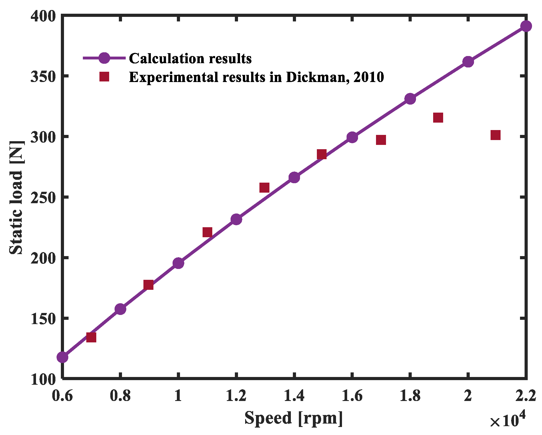
3.2. Validation of Theoretical Analysis Method

Before formal analysis, it is necessary to validate the reliability of the theoretical analysis method developed in this study. Since liquid nitrogen presents some challenges in sealing and measurement, there are no existing experimental data tested in liquid nitrogen for comparison. Therefore, the developed analysis method is employed to calculate the performance of gas foil bearings, and a comparison between calculation results and experimental results is performed. Dickman [37] presented sufficient experimental results of thrust-type foil bearings lubricated by gas, which can be used for comparison. To match the experimental conditions, the top foil thickness is set at 0.1524 mm, the unfolding angles of the top and bump foils are set at 45°, and the tilted plane unfolding angle is set at 15°. Other bearing parameters are consistent with those listed in Table 1. The friction coefficients of all contact surfaces are set as μ = 0.2 and η = 0.2. The wedge height ht is set at 40 μm. The minimum initial film thickness h2 is set at 5 μm. As shown in Figure 5, the static load obtained from theoretical calculations is compared with the experimental data. The experimental values gradually decrease at high speeds. This is because some regions of the foil structure cannot dissipate heat in time, causing thermal deformation of the top foil, which ultimately leads to a reduction in the measured static load of the bearing. In theoretical calculations, the thermal effects of the lubricating gas are not considered, resulting in a linear increase in the theoretical values without the observed decrease. It can also be observed that the calculated results are consistent with experimental values at low rotational speeds, which validate the reliability of the theoretical analysis method developed in this study.

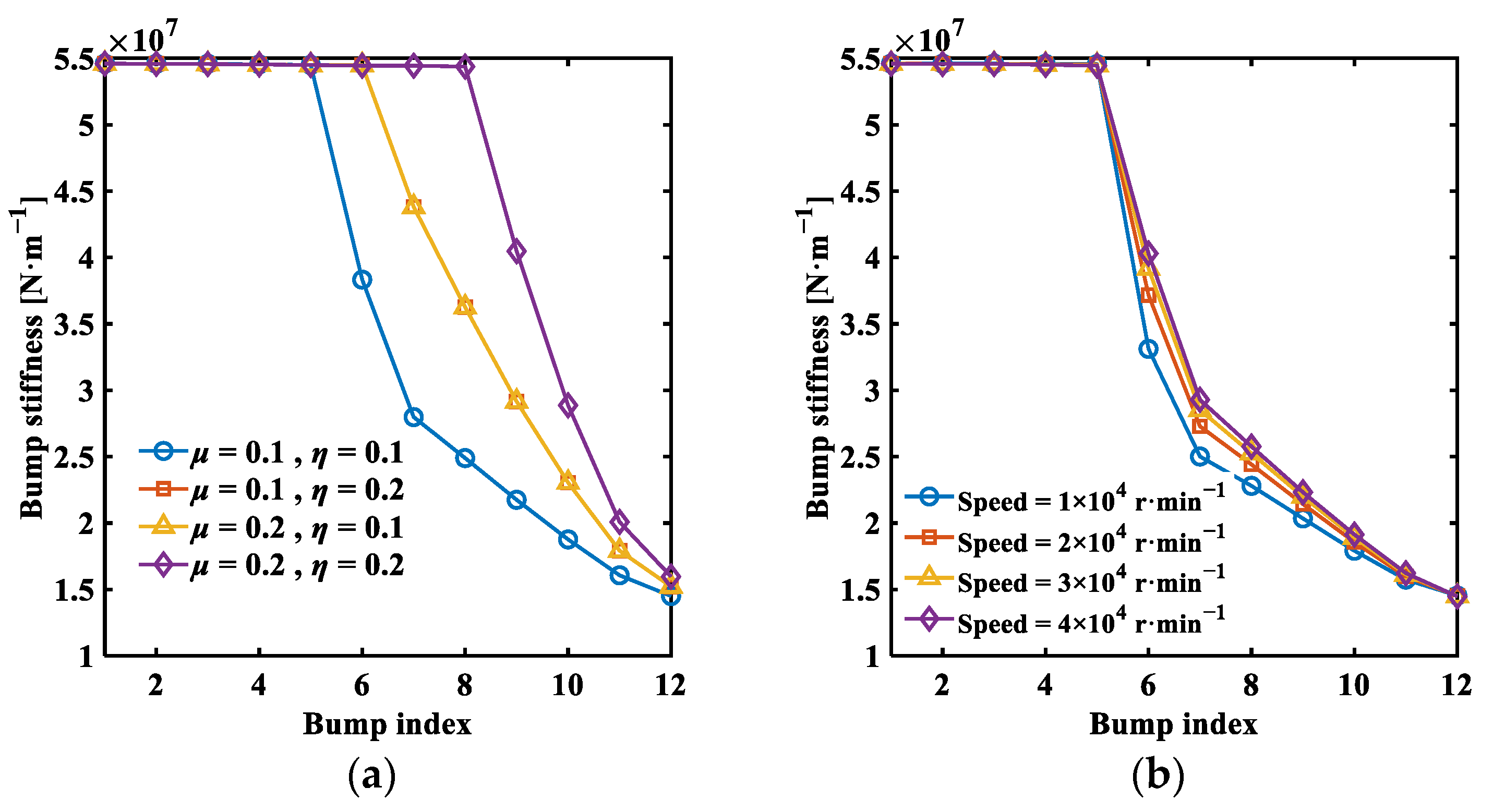
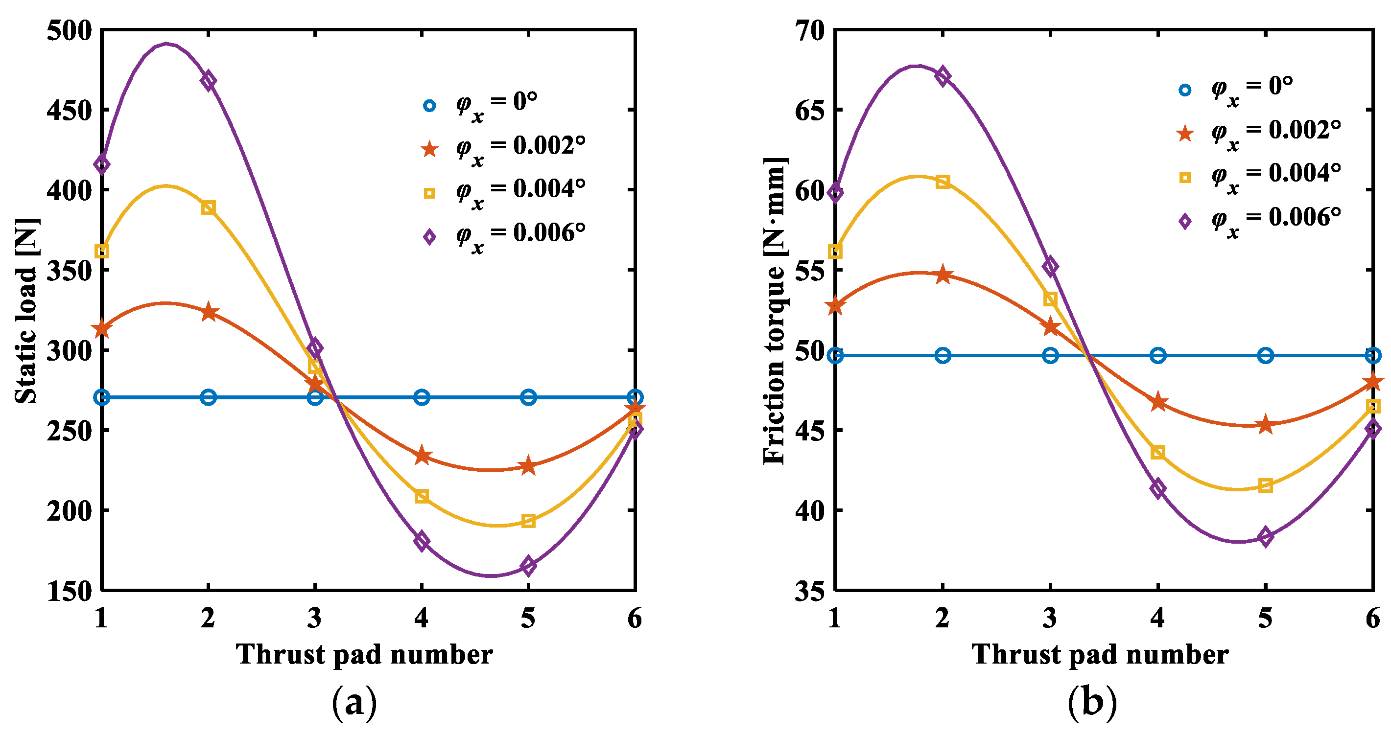
3.3. Analysis Results of Static Characteristics

The deformation of the foil structure directly affects the distribution of fluid film pressure, which significantly impacts the bearing performance. Figure 6a shows the distribution of equivalent stiffness of the bump foils at different friction coefficients when the speed is 2.5 × 10⁴ r·min−1. It can be seen that the bump foils with the same stiffness are fixed, and those with different stiffness are located in the slip region, indicating that the fixed bump foils have significantly higher stiffness. Moreover, as the friction coefficient increases, the number of fixed bump foils increases, and the stiffness of the bump foils in the slip region also increases. Figure 6b shows the distribution of equivalent stiffness of the bump foils at friction coefficients of μ = 0.1 and η = 0.1 and different speeds. It is evident that an increase in speed increases the stiffness of the bump foils that can slip, indicating the nonlinear characteristics of bump foil stiffness. This characteristic is not only related to structural parameters but also influenced by changes in static loads. A decrease in rotational speed reduces the hydrodynamic lubrication effect, significantly reducing the static load on the bearing. It can be concluded that there is a nonlinear dynamic response relationship between bump foil stiffness and load-carrying capacity. An increase in load causes the bump foil stiffness to increase to resist the larger deformations of the top foil. This adaptive response characteristic enables the foil bearing to have good viscous damping properties, greatly reducing system vibration and improving system stability.
The tilt of the thrust disk causes uneven film thickness across each pad, leading to an uneven distribution of film pressure. Figure 7 shows the distributions of pressure and foil deformation under a tilt angle of φ x = 0.004°. It can be seen that the tilt of the rotor results in uneven film thickness, with the fluid film pressure distribution of pad 2 being the highest and pad 5 being the lowest. Under the combination effects of large viscosity, high supply pressure, and high rotational speed, a maximum fluid film pressure of 2.0773 MPa is generated. At the same time, local depressions between adjacent bump foils result in uneven stiffness distribution, causing the foil to deflect and the pressure distribution to exhibit a wavy pattern. Where the pressure is higher, the deflection of the foil is greater, and the local depressions are more pronounced. Additionally, it can be observed that, closer to the free end, there are more slip bump foils, leading to a lower stiffness of the bump foils and thus a greater deflection of the foils near the free end compared to those near the fixed end.
An appropriate friction coefficient is one of the key factors affecting bearing performance. Figure 8 illustrates the effect of the friction coefficient on the static characteristics of the bearing under different rotational speeds. It can be observed that both the static load and the friction torque of the bearing increase with an increase in the friction coefficient, approaching a constant value. As the speed increases, the gradient of the change in static load and friction torque with respect to the friction coefficient also increases. These results indicate that, at high speeds, the increase in bearing load results in greater deformation of the foil structure. In contrast, at low speeds, the lower static load of the bearing means that the change in the friction coefficient does not cause significant deformation of the foil structure compared to the original film thickness, thus significantly altering the distribution of film thickness. This highlights the more pronounced impact of the friction coefficient on the static load of the bearing at high speeds. Additionally, an increase in the friction coefficient gradually increases the number of fixed bump foils. When the friction coefficient reaches a certain limit, the number of fixed bump foils does not continue to increase, and the increase in the equivalent stiffness of the bump foils slows down. Therefore, the static load and friction torque gradually approach a constant value.
Figure 9 illustrates the effect of the initial minimum film thickness on the static characteristics of the bearing at different speeds. It can be observed that both the static load and the friction torque of the bearing increase rapidly as the minimum film thickness decreases, with the rate of change gradually accelerating. As the operating speed increases, the static load and friction torque of the bearing increase, but their rate of increase gradually slows down.
Figure 10 shows the effect of wedge height on the static characteristics of the bearing at different speeds. It can be observed that the static load of the bearing increases initially and then decreases with an increase in wedge height, while the friction torque decreases with an increase in wedge height, with the rate of change gradually decreasing. The reason for this is as follows: when the wedge height is relatively small, increasing the wedge height makes the compression effect of the film more pronounced, leading to an increase in load-carrying capacity. However, when the wedge height increases to a certain extent, although the maximum pressure increases, the film gap in the wedge region also enlarges, causing a rapid pressure drop in this part of the region. This reduces the effective pressure area, leading to a decrease in load-carrying capacity. Therefore, there exists an optimal value for the wedge height in bearing design to achieve the maximum load-carrying capacity.
When the thrust disk tilts, it results in a different distribution of film thickness. Figure 11 and Figure 12 show the distribution of static characteristics of the bearing under an X-axis tilt of the thrust disk. From Figure 11, it can be seen that the bearing load and friction torque change trend with the thrust disk number is the same as the decrease in film thickness caused by the misalignment of the thrust disk in the circumferential angle direction. When deflected along the X-axis, it exhibits a sinusoidal distribution, with the amplitude of the distribution curve increasing with the tilt angle.
From Figure 12, it can be seen that the overall static load and friction torque of the bearing both exhibit an exponential increase with the rise in tilt angle, using n b to represent the ratio of the calculated bump foil thickness to the original bump foil thickness t b . Increasing the thickness ratio of the bump will increase both the static load and friction torque. When the bump foil thickness is relatively small, the equivalent vertical stiffness provided by the bump foil structure decreases accordingly. As a result, the deformation of the top foil increases, thereby increasing the thickness of the fluid film under the same load. When the bump foil thickness reaches a critical value, the effect of foil deformation relative to the original film thickness is almost zero, and further increasing the bump foil thickness will not increase the static load and friction torque of the bearing.

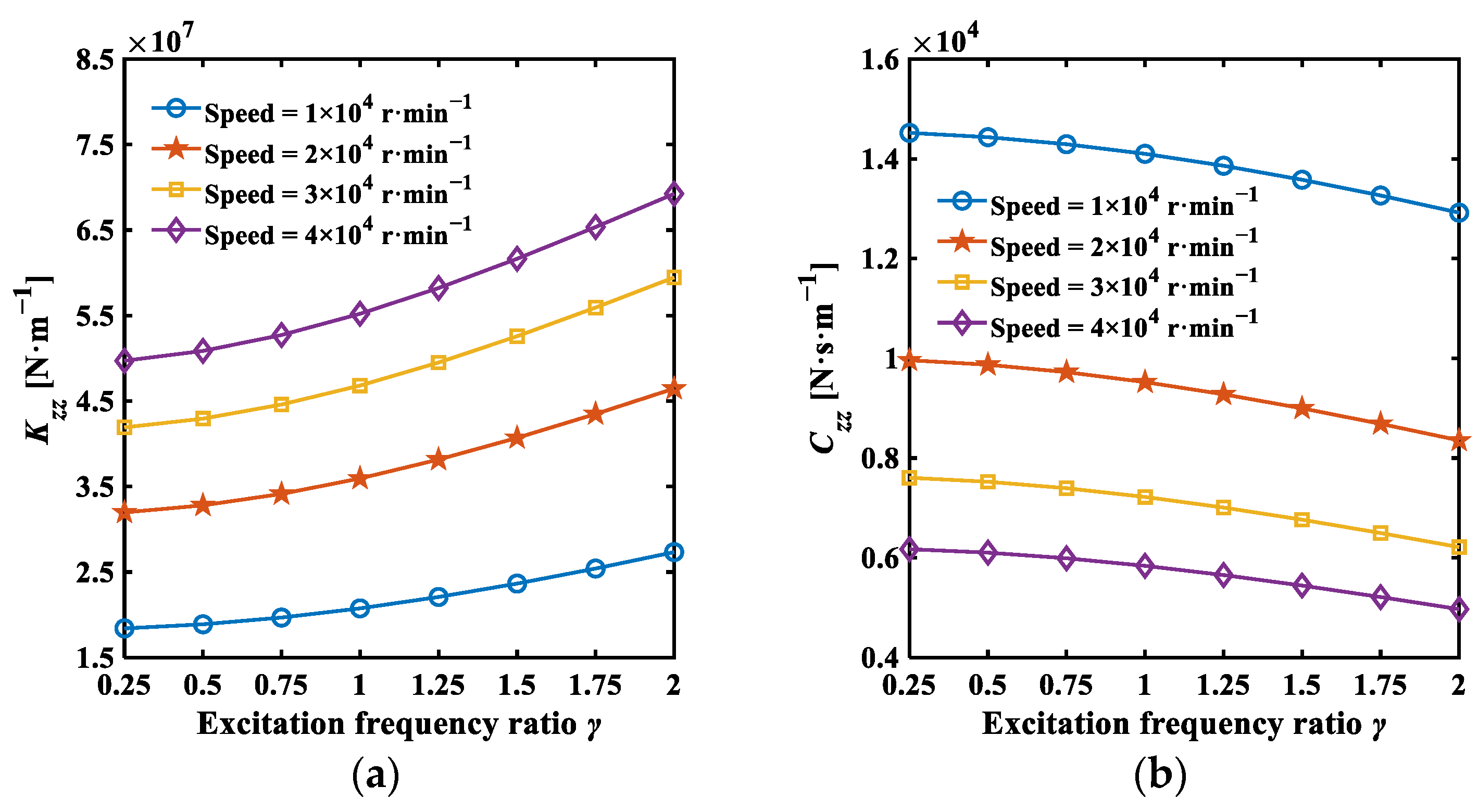
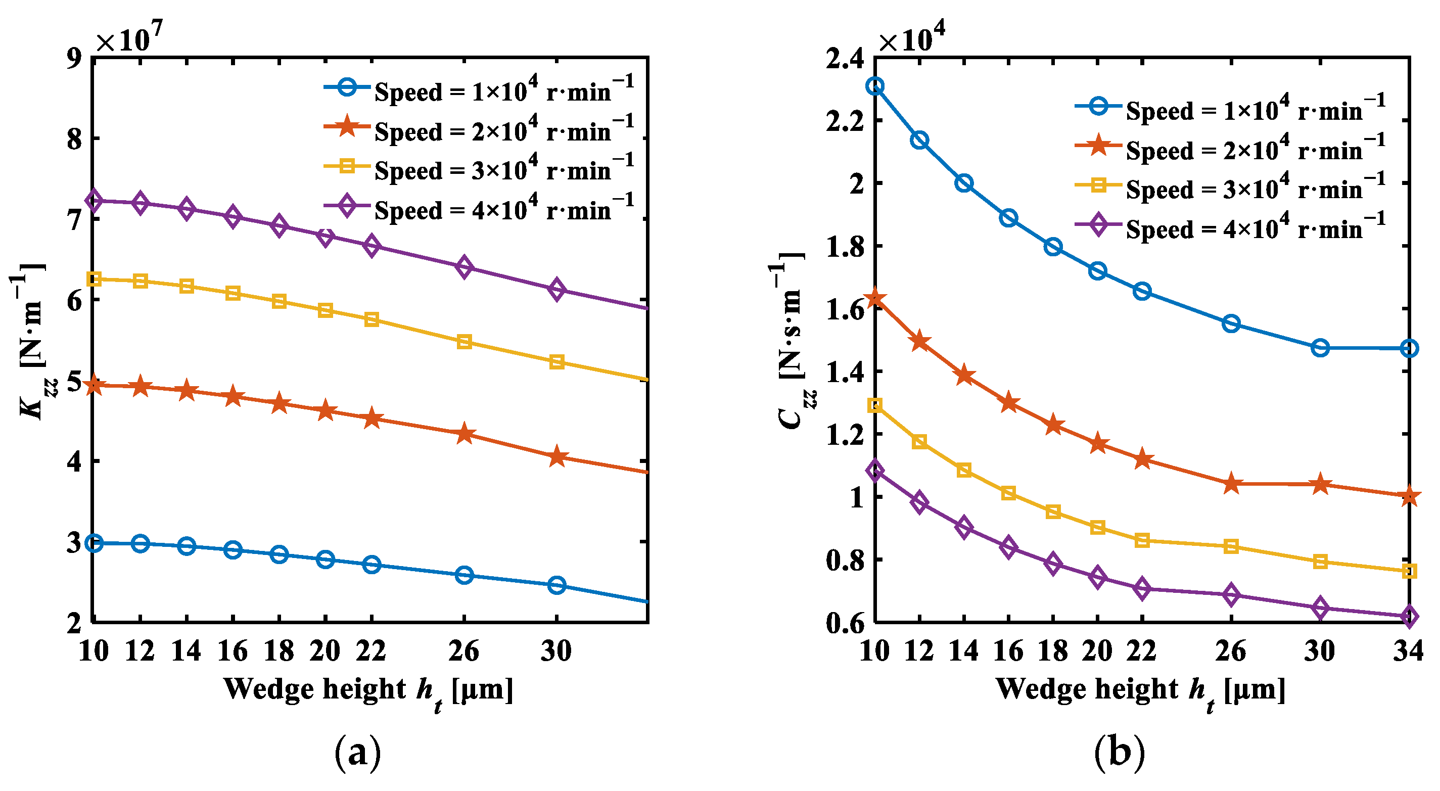
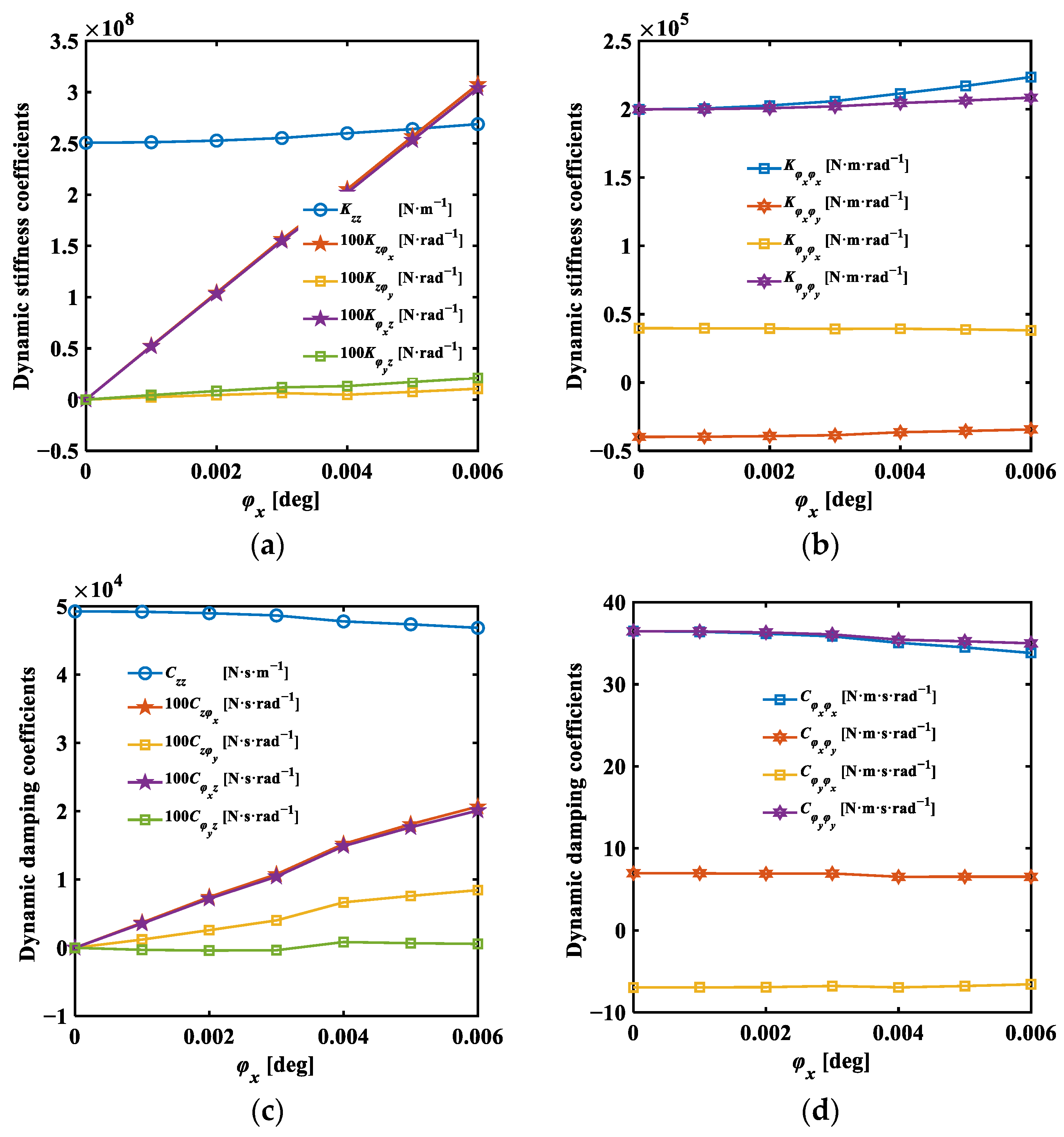
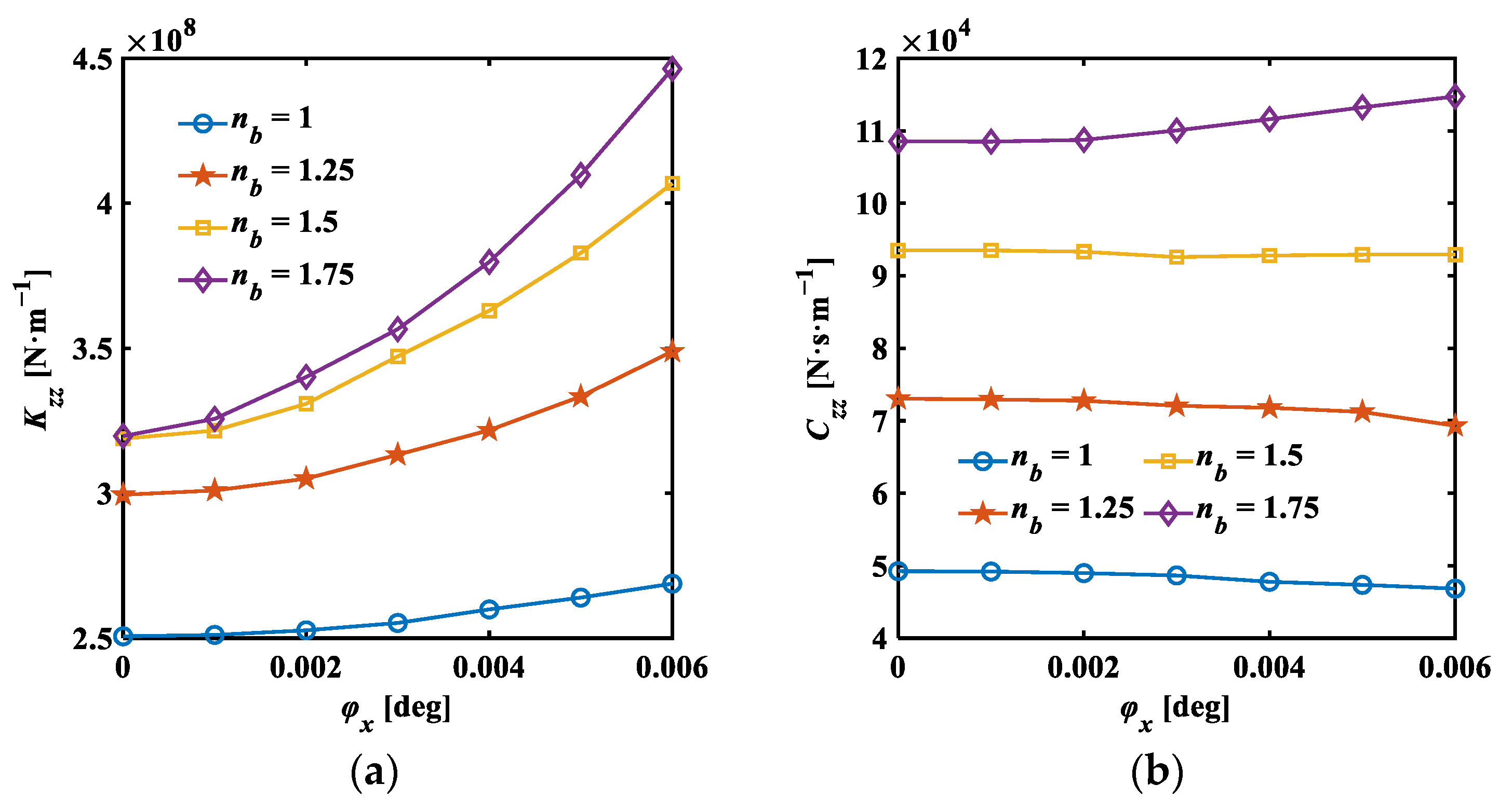
3.4. Analysis Results of Dynamic Characteristics

The stiffness and damping coefficients of the bearing are directly affected by the tilt angle of the thrust disk. When the thrust disk is not tilted, the dynamic stiffness and damping coefficients of the bearing exhibit a skew-symmetric distribution. The cross-coupling stiffness and damping coefficients ( K z φ x ,   K φ x z ,   K z φ y ,   K φ y z ,   C z φ x ,   C φ x z ,   C z φ y ,   C φ y z ) are both zero, the rotational cross-coupling stiffness–damping coefficients are equal ( K φ x φ y = K φ y φ x ,   C φ x φ y = C φ y φ x ), and the direct rotational stiffness–damping coefficients are also equal ( K φ x φ x = K φ y φ y ,   C φ x φ x = C φ y φ y ). However, compared to the direct translational stiffness–damping coefficients ( K z z   C z z ), the amplitude of the rotational stiffness–damping coefficients is smaller. The dynamic performance of the bearing is primarily determined by the direct stiffness–damping coefficients ( K z z   C z z ) because, when the tilt angle of the thrust-type foil bearing is zero, the film thickness distribution is symmetric with respect to the X and Y axes, resulting in very small coupling effects between translational and tilt motions. Therefore, unless otherwise specified, the dynamic analysis of thrust-type foil bearings is conducted assuming there is no tilt of the thrust disk, resulting in the calculation of the direct translational stiffness–damping coefficients of a thrust pad.
Figure 13 investigates the effect of different excitation frequency ratios on the direct translational stiffness and damping coefficients of the bearing. It can be observed that, as the excitation frequency increases, the direct translational stiffness coefficient increases, while the direct translational damping coefficient decreases. This is because the increase in excitation frequency leads to a greater squeeze effect on the lubricating film, thereby increasing the pressure distribution.
Figure 14 illustrates the effect of different friction coefficients on the direct translational stiffness and damping coefficients. It can be observed that an increase in the friction coefficient leads to the higher equivalent stiffness of the bump foils, resulting in an increase in both the direct translational stiffness and damping coefficients. Increasing the rotational speed also enhances the rate of growth of the stiffness and damping coefficients. This indicates that, at high speeds, the dynamic stiffness–damping coefficients are more sensitive to the friction coefficient. This is because, at higher speeds, there is a higher load-carrying capacity, forcing the foil structure to undergo larger deformations. In contrast, at lower speeds, the lower load-carrying capacity means that an increase in the friction coefficient does not cause significant deformation of the foil structure compared to the original film thickness, thus not significantly affecting the film pressure distribution.
Figure 15 illustrates the effect of the minimum film thickness on the direct translational stiffness and damping coefficients. It shows that, at a specific speed, increasing the minimum film thickness reduces the static load of the bearing, leading to a continuous decrease in both the direct translational stiffness and damping coefficients, with the rate of decrease slowing down. Additionally, increasing the speed causes the direct translational stiffness coefficient to gradually increase and the direct translational damping coefficient to gradually decrease, with the growth rate of both coefficients decreasing with speed.
Figure 16 displays the effect of wedge height on the direct translational stiffness and damping coefficients. It can be observed that, at the same speed, increasing the wedge height leads to a rapid decrease in the direct translational stiffness and a gradual decrease in the direct translational damping coefficient, approaching a certain value. As speed increases, the direct translational stiffness coefficient increases while the direct translational damping coefficient decreases, but the rate of both coefficients decreases with speed.
To investigate the effect of tilt angle of the thrust disk on bearing stiffness, φ x is selected as the variable, and its effects on the overall dynamic stiffness–damping coefficients of the thrust-type foil bearing are analyzed. Figure 17 indicates that, as the tilt angle of the thrust disk increases, the direct translational stiffness increases while the direct translational damping coefficient decreases. However, the magnitude of these changes is small, reflecting the adaptive response characteristics of the foil structure, allowing it to deform to improve the composition of the film thickness in response to load changes. Additionally, due to the small thickness of the foils used in this study, they can undergo significant deformation. Therefore, compared to rigid bearings, the thrust-type foil bearings used in this study show a smaller change in stiffness with tilt angle, indicating greater stability.
Furthermore, the combined effect of static and dynamic misalignment about the X-axis leads to non-recoverable and non-dissipative forces in the film, manifested as the rapid increase in the cross-coupling stiffness and damping coefficients ( K z φ x   ,   K φ x z   ,   C z φ x   ,   C φ x z ) from zero. However, they are not symmetrically equal ( K z φ x = K φ x z   ,   C z φ x = C φ x z ), and their difference increases with the tilt angle. Nevertheless, compared to the direct translational coefficients ( K z z   ,   C z z ), their values remain small, thereby maintaining the stability of the bearing. Moreover, it can also be observed that, since there is no static deviation around the y-axis ( φ y = 0), the cross-coupling stiffness and damping coefficients ( K z φ y   ,   K φ y z   ,   C z φ y   ,   C φ y z ) are not as sensitive to the static deviation factor ( φ x ). Therefore, the increase in the cross-coupling stiffness and damping coefficients ( K z φ y   ,   K φ y z   ,   C z φ y   ,   C φ y z ) is due to the increase in bearing pressure caused by the tilt of the thrust disk.
The trend in the rotational direct stiffness and damping coefficients ( K φ x φ x   ,   K φ y φ y   ,   C φ x φ x   ,   C φ y φ y ) is similar to that of the direct translational stiffness and damping coefficients ( K z z   ,   C z z ). As the tilt angle ( φ x ) increases, the rotational direct stiffness coefficient ( K φ x φ x   ,   K φ y φ y   ) increases, while the rotational direct damping coefficient ( C φ x φ x   ,   C φ y φ y ) decreases. The rotational cross-coupling stiffness and damping coefficients ( K φ x φ y   ,   K φ y φ x   ,   C φ x φ y   ,   C φ y φ x ) are not as sensitive to the static deviation factor ( φ x ), and their values are also very small and can be ignored. Therefore, even with a slight tilt of the thrust disk, the rotational stiffness–damping coefficients and the cross-coupling stiffness–damping coefficients remain very small, and the direct translational stiffness–damping coefficients play a dominant role.
Figure 18 illustrates the effect of the tilt angle of the thrust disk on the direct translational dynamic stiffness and damping coefficients of the thrust-type foil bearing under different bump foil thickness ratios. The direct translational stiffness coefficient increases with the tilt angle and tends to stabilize as bump foil thickness increases. In contrast, the direct translational damping coefficient is influenced by both tilt angle and bump foil thickness. Increasing bump foil thickness changes the trend of the direct translational damping coefficient from a decrease with tilt angle to an increase. This occurs because a greater bump foil thickness enhances the stiffness of the bump foils, gradually reducing the foil deformation to nearly zero, thereby increasing the static load of the bearing and subsequently increasing the direct translational stiffness and damping coefficients.

4. Conclusions

In this study, liquid nitrogen is adopted to simulate the ultra-low temperature environment of liquid rocket turbopumps and theoretical evaluations of the lubrication performance of thrust-type foil bearings in liquid nitrogen are conducted. The deformation equation of the foil is established using the link-spring model and a finite element model. The perturbation method is used to solve the Reynolds lubrication equation, resulting in one steady pressure equation and six pressure perturbation equations. The finite difference method and the Newton–Raphson iteration method are employed for solving and analyzing the effects of parameters such as film thickness, rotational speed, and tilt angle on the static and dynamic performances of the thrust bearing. Based on the simulation results, the following conclusions are drawn:
  • Through the analysis of static characteristics, it is observed that increasing the friction coefficient and decreasing the initial minimum film thickness enhance the static load and friction torque of the bearing. There is an optimal wedge height that achieves a higher load-carrying capacity while minimizing friction torque and reducing power loss. The severe tilt of the thrust disk causes the uneven distribution of fluid film thickness across the thrust pad, affecting the bearing stability. Reducing the bump foil thickness effectively increases top foil deformation, enhancing the fluid film thickness but decreasing the static load-carrying capacity of the bearing.
  • Through the analysis of dynamic characteristics, it is observed that increasing the excitation frequency enhances the direct translational stiffness of the thrust-type foil bearing, while the damping coefficient decreases. Moreover, both the direct translational stiffness and damping coefficients increase with the friction coefficient and the bump foil’s thickness, yet decrease with an increase in the minimum initial film thickness and wedge height. The tilt of the thrust disk notably impacts the cross-coupling stiffness and damping coefficients ( K z φ x   ,   K φ x z   ,   C z φ x   ,   C φ x z ), which escalate rapidly with tilt, significantly affecting system stability. Therefore, substantial tilts of the thrust disk should be avoided.
  • Different from rolling bearings, thrust-type foil bearings exhibit adaptive response characteristics and operate with completely non-contact lubrication during the working stage, which can reduce the risk of contact and wear between the bearing and rotor. The low-temperature conditions in liquid rocket turbopumps effectively cool the bearings, preventing performance degradation due to thermal effects. Moreover, thrust-type foil bearings are characterized by high operating speeds, a compact structure, maintenance-free operation, and a high load-carrying capacity, all of which meet the requirements for repeated use. Therefore, based on the results in this study, the exceptional performance characteristics of thrust-type foil bearings make them a promising alternative to rolling bearings for the development of reusable liquid rocket turbopumps.

Author Contributions

Conceptualization, J.X.; methodology, H.D. and T.J.; software, H.D. and T.J.; validation, H.D. and L.H.; formal analysis, J.X., H.D., and S.C.; investigation, J.X., S.C., H.D., and X.F.; data curation, J.X., H.D., and X.F.; writing—original draft preparation, J.X. and H.D.; visualization, H.D. and L.H.; supervision, J.X. and X.F.; project administration, J.X.; funding acquisition, J.X. All authors have read and agreed to the published version of the manuscript.

Funding

This research was funded by the National Natural Science Foundation of China (Grant No. 52175165 and 52411540029) and the Open project of Anhui Province Key Laboratory of Critical Pair for Advanced Equipment (Grant No. LCFP-2405).

Data Availability Statement

The original contributions presented in the study are included in the article; further inquiries can be directed to the corresponding author.

Conflicts of Interest

The authors declare no conflicts of interest.

Nomenclature

bPitch ratio (proportion of the tilted plane in the sector thrust pad)
CijDynamic damping coefficients (i, j = z, φ x , φ y )
EYoung’s modulus [Pa]
FloadStatic load [N]
gWedge surface clearance [m]
hFilm thickness [m]
hbFoil height [m]
h1Inlet film thickness [m]
h2Outlet film thickness [m]
htWedge height [m]
h φ Tilt clearance thickness caused by rotor misalignment [m]
HDimensionless film thickness
KijDynamic stiffness coefficients (i, j = z, φ x , φ y )
KfOverall stiffness matrix [N/m]
KtTop foil stiffness matrix [N/m]
KvEffective stiffness matrix of the foil [N/m]
lbHalf bump length [m]
nbBump foil thickness ratio
NFilm thickness ratio (h1/h2)
pFilm pressure [Pa]
PDimensionless film pressure
PsSupply pressure [Pa]
P0Steady-state dimensionless film pressure
P ς , P ς ˙ Perturbation pressure ( ς = z, φ x , φ y )
rAxial coordinate [m]
r1Inner diameter of the thrust pad [m]
r2Outer diameter of the thrust pad [m]
tTime variable [s]
t ¯ Dimensionless time variable
t b Bump foil thickness [m]
t f Top foil thickness [m]
TcFriction torque [N·m]
zAxial coordinate [m]
β Angular range of the top foil and bump foil [°]
δ Foil deformation [m]
δ ¯ Dimensionless foil deformation
η Coefficient of friction between the bump foil and the top foil
γ Excitation frequency ratio
Λ Bearing number, Λ = 6 μ 0 ω r 2 2 / ( P s h 2 2 )
μ Coefficient of friction between the bump foil and the bearing housing
μ 0 Dynamic viscosity of liquid nitrogen [Pa·s]
ν Poisson’s ratio of the top foil and bump foil
ω Angular speed of the shaft [rad/s]
ω e Excitation frequency [rad/s]
θ Circumferential coordinate [°]
φ x Tilt angle in the X-axis direction [°]
φ y Tilt angle in the Y-axis direction [°]

References

  1. Okayasy, A.; Ohta, T.; Kamijyo, A.; Yamada, H. Key technology for reusable rocket engine turbopump. Acta Astronaut. 2002, 50, 351–355. [Google Scholar] [CrossRef]
  2. Lance, A.D. First stage recovery. Engineering 2016, 2, 152–153. [Google Scholar]
  3. Baiocco, P. Overview of reusable space systems with a look to technology aspects. Acta Astronaut. 2021, 189, 10–25. [Google Scholar] [CrossRef]
  4. Baiocco, P.; Bonnal, C. Technology demonstration for reusable launchers. Acta Astronaut. 2016, 120, 43–58. [Google Scholar] [CrossRef]
  5. Xu, J.; Li, C.; Miao, X.; Zhang, C.; Yuan, X. An overview of bearing candidates for the next generation of reusable liquid rocket turbopumps. Chin. J. Mech. Eng. 2020, 33, 26. [Google Scholar] [CrossRef]
  6. Xu, J.; Zhang, C.; Wang, J.; Wang, W. Experimental investigations of novel compound bearing of superconducting magnetic field and hydrodynamic fluid field. IEEE Trans. Appl. Supercond. 2020, 30, 3600407. [Google Scholar] [CrossRef]
  7. Nosaka, M.; Takada, S.; Kikuchi, M.; Sudo, T.; Yoshida, M. Ultra-high-speed performance of ball bearings and annular seals in liquid hydrogen at up to o 3 million DN (120000 rpm). Tribol. Trans. 2004, 47, 43–53. [Google Scholar] [CrossRef]
  8. Lv, F.; Shangguan, Y.; Zou, D.; Ji, A. Transient mixed-lubrication analysis of low-viscosity lubricated bearings under impact load with consideration of turbulence. Phys. Fluids 2022, 34, 033108. [Google Scholar] [CrossRef]
  9. Deng, X. Study of temperature drop region in transitional region in fluid-film thrust bearings. J. Fluids Eng.-Trans. ASME 2024, 146, 121201. [Google Scholar] [CrossRef]
  10. Deng, X. A mixed zero-equation and one-equation turbulence model in fluid-film thrust bearings. J. Tribol.-Trans. ASME 2024, 146, 034101. [Google Scholar] [CrossRef]
  11. Deng, X.; Harrison, G.; Roger, F.; Houston, W. Methodology of turbulence parameter correction in water-lubricated thrust bearings. J. Fluids Eng.-Trans. ASME 2019, 141, 070014. [Google Scholar] [CrossRef]
  12. Deng, X.; Brian, W.; Cori, W.; Michael, B.; Houston, W.; Roger, F. Modeling Reichardt’s formula for eddy viscosity in the fluid film of tilting pad thrust bearings. J. Eng. Gas Turbines Power 2018, 140, 082505. [Google Scholar] [CrossRef]
  13. Hannum, N.; Nielson, C. The performance and application of high speed long life hybrid bearings for reusable rocket engine turbomachinery. In Proceedings of the 19th Joint Propulsion Conference cosponsored by the AIAA, SAE and ASME, Seattle, WA, USA, 27–29 June 1983. [Google Scholar]
  14. Ohta, T.; Kitamura, A.; Ogata, H. LH2 turbopump test with hydrostatic bearing. In Proceedings of the 35th AIAA/ASME/SAE/ASEE Joint Propulsion Conference and Exhibit, Los Angeles, CA, USA, 20–24 June 1999. [Google Scholar]
  15. Fayolle, P.; Lambert, P.-A.; Gelain, P.; Fonteyn, P.; Olofsson, H.; Ore, S.; Supie, P.; Dehouve, J. Major achievements reached through TPX LH2-turbopump demonstration program. In Proceedings of the 47th AIAA/ASME/SAE/ASEE Joint Propulsion Conference & Exhibit, San Diego, CA, USA, 31 July–3 August 2011. [Google Scholar]
  16. Mertz, D.H. Lift-Off Performance in Flexure Pivot Pad and Hybrid Bearing. Master’s Thesis, Texas A&M University, College Station, TX, USA, 2008. [Google Scholar]
  17. Xu, J.; Chen, R.; Hong, H.; Yuan, X.; Zhang, C. Static characteristics of high-temperature superconductor and hydrodynamic fluid-film compound bearing for rocket engine. IEEE Trans. Appl. Supercond. 2015, 25, 3601908. [Google Scholar] [CrossRef]
  18. Xu, J.; Yuan, X.; Zhang, C.; Miao, X. Dynamic characteristics of high-Tc superconductor and hydrodynamic fluid-film compound bearing for rocket engine. IEEE Trans. Appl. Supercond. 2016, 26, 3600505. [Google Scholar]
  19. Heshmat, H. A feasibility study on the use of foil bearings in cryogenic turbopumps. In Proceedings of the 27th AIAA/SAE/ASME/ASEE Joint Conference, Sacramento, CA, USA, 24–27 June 1991. [Google Scholar]
  20. Guo, Z.; Feng, K.; Liu, T.; Lyu, P.; Zhang, T. Nonlinear dynamic analysis of rigid rotor supported by gas foil bearings: Effects of gas film and foil structure on subsynchronous vibrations. Mech. Syst. Signal. Pract. 2018, 107, 549–566. [Google Scholar] [CrossRef]
  21. Gu, A. Cryogenic foil bearing turbopumps. In Proceedings of the 32nd Aerospace Sciences Meeting & Exhibit, Reno, NV, USA, 10–13 January 1994. [Google Scholar]
  22. Guan, H.; Li, J.; Wei, K.; Zou, H. Rotordynamics of a rotor radially and axially supported by active bump-type foil bearings and bump-type thrust bearings. Mech. Syst. Signal. Pract. 2024, 208, 110995. [Google Scholar] [CrossRef]
  23. Shi, J.; Cao, H.; Jin, X. Investigation on the static and dynamic characteristics of 3-DOF aerostatic thrust bearings with orifice restrictor. Tribol. Int. 2019, 138, 435–449. [Google Scholar] [CrossRef]
  24. Xu, Z.; Li, C.; Du, J.; Li, J.; Wang, Y. Load-carrying characteristics of bump-type gas foil thrust bearings. Int. J. Mech. Sci. 2023, 244, 108080. [Google Scholar] [CrossRef]
  25. Chen, R.; Zhao, Y.; Yao, J.; Wang, Z. Research on the performance of foil bearings under dynamic disturbances. Tribol. Int. 2022, 174, 107744. [Google Scholar] [CrossRef]
  26. Feng, K.; Liu, L.J.; Guo, Z.Y.; Zhao, X.Y. Parametric study on static and dynamic characteristics of bump-type gas foil thrust bearing for oil-free turbomachinery. Proc. Inst. Mech. Eng. J.—J. Eng. 2016, 230, 944–961. [Google Scholar] [CrossRef]
  27. Somaya, K.; Kishino, T.; Miyatake, M.; Yoshimoto, S. Static characteristics of small aerodynamic foil thrust bearings operated up to 350,000 r/min. Proc. Inst. Mech. Eng. J.—J. Eng. 2014, 228, 928–936. [Google Scholar] [CrossRef]
  28. Lee, D.; Kim, D. Design and performance prediction of hybrid air foil thrust bearings. J. Eng. Gas Turbines Power 2011, 133, 042501. [Google Scholar] [CrossRef]
  29. LaTray, N.; Kim, D. Design of novel gas foil thrust bearings and test validation in a high-speed test rig. J. Tribol.-Trans. ASME 2020, 142, 071803. [Google Scholar] [CrossRef]
  30. Li, C.; Du, J.; Yao, Y. Modeling of a multi-layer foil gas thrust bearing and its load carrying mechanism study. Tribol. Int. 2017, 114, 172–185. [Google Scholar] [CrossRef]
  31. Guo, Y.; Hou, Y.; Wang, Y.; Zhao, Q.; Zheng, Y.; Lai, T. Numerical analysis of aerodynamic lubricated double-decked protuberant foil thrust bearing. J. Adv. Mech. Des. Syst. 2019, 13, JAMDSM0056. [Google Scholar] [CrossRef]
  32. Lee, D.; Kim, D. Three-dimensional thermohydrodynamic analyses of Rayleigh step air foil bearing with radially arranged bump foils. Tribol. Trans. 2011, 54, 432–448. [Google Scholar] [CrossRef]
  33. Gad, A.M.; Kaneko, S. Performance characteristics of gas-lubricated bump-type foil thrust bearing. Proc. Inst. Mech. Eng. J.—J. Eng. 2015, 229, 746–762. [Google Scholar] [CrossRef]
  34. Gad, A.M. On the performance of foil thrust bearing with misaligned bearing runner. Ind. Lubr. Tribol. 2017, 69, 105–115. [Google Scholar] [CrossRef]
  35. Feng, K.; Kaneko, S. Analytical model of bump-type foil bearings using a link-spring structure and a finite-element shell mode. J. Tribol.-Trans. ASME 2010, 132, 021706. [Google Scholar] [CrossRef]
  36. Jang, G.H.; Kim, Y.J. Calculation of dynamic coefficients in a hydrodynamic bearing considering five degrees of freedom for a general rotor-bearing system. J. Tribol.-Trans. ASME 1999, 121, 499–505. [Google Scholar] [CrossRef]
  37. Dickman, J.R. An Investigation of Gas Foil Thrust Bearing Performance and Its Influencing Factors. Master’s Thesis, Case Western Reserve University, Cleveland, OH, USA, 2010. [Google Scholar]
Figure 1. (a) Structural diagram of the thrust-type foil bearing, and (b) schematic diagram of the fluid film.
Lubricants 12 00257 g001
Figure 2. Coordinate system of thrust-type bearing considering rotor misalignment.
Lubricants 12 00257 g002
Figure 3. Link-spring model of bump foils.
Lubricants 12 00257 g003
Figure 4. Flow diagram for calculating the static and dynamic characteristics of thrust-type foil bearings.
Lubricants 12 00257 g004
Figure 5. Comparison between theoretical calculation results using analysis method developed in this study and experimental results in Dickman, 2010 [37].
Lubricants 12 00257 g005
Figure 6. Effect of (a) friction coefficient and (b) rotational speed on bump foil stiffness (N = 5, h2 = 10 μm).
Lubricants 12 00257 g006
Figure 7. Distributions of (a) fluid film pressure and (b) foil deformation with thrust disk inclined at φ x = 0.004° (speed = 2.5 × 10⁴ r·min−1, N = 5, h2 = 10 μm, μ = 0.1, η = 0.1).
Lubricants 12 00257 g007
Figure 8. Impact of friction coefficient on (a) static load and (b) friction torque of thrust pads (N = 5, h2 = 10 μm, η = 0.1).
Lubricants 12 00257 g008
Figure 9. Impact of minimum initial fluid film thickness on (a) static load and (b) friction torque of thrust pads (ht = 26 μm, μ = 0.1, η = 0.1).
Lubricants 12 00257 g009
Figure 10. Impact of wedge height on (a) static load and (b) friction torque of thrust pads (h2 = 10 μm, μ = 0.1, η = 0.1).
Lubricants 12 00257 g010
Figure 11. Impact of thrust disk inclination angle on (a) static load and (b) friction torque of thrust pads (speed = 2.5 × 10⁴ r·min−1, N = 5, h2 = 10 μm, μ = 0.1, η = 0.1).
Lubricants 12 00257 g011
Figure 12. Impact of thrust disk inclination angle on (a) static load and (b) friction torque of thrust-type foil bearings (speed = 2.5 × 10⁴ r·min−1, N = 5, h2 = 10 μm, μ = 0.1, η = 0.1).
Lubricants 12 00257 g012
Figure 13. Effect of excitation frequency ratio on (a) direct translational stiffness and (b) damping coefficients of thrust pads (N = 5, h2 = 10 μm, μ = 0.1, η = 0.1).
Lubricants 12 00257 g013
Figure 14. Effect of friction coefficient on (a) direct translational stiffness and (b) damping coefficients of thrust pads (N = 5, h2 = 10 μm, μ = 0.1, η = 0.1).
Lubricants 12 00257 g014
Figure 15. Effect of minimum initial fluid film thickness on (a) direct translational stiffness and (b) damping coefficients of thrust pads (ht = 26 μm, μ = 0.1, η = 0.1).
Lubricants 12 00257 g015
Figure 16. Effect of wedge height on (a) direct translational stiffness and (b) damping coefficients of thrust pads (h2 = 10 μm, μ = 0.1, η = 0.1).
Lubricants 12 00257 g016
Figure 17. Effect of thrust disk inclination angle on the dynamic stiffness and dynamic damping coefficients of thrust-type foil bearings (speed = 2.5 × 10⁴ r·min−1, N = 5, h2 = 10 μm, μ = 0.1, η = 0.1): (a,b) dynamic stiffness coefficients; (c,d) dynamic damping coefficients.
Lubricants 12 00257 g017
Figure 18. Effect of thrust disk inclination angle on the (a) direct translational stiffness and (b) damping coefficients of the thrust-type foil bearings under different bump foil thickness ratios (rotational speed = 2.5 × 10⁴ r·min−1, N = 5, h2 = 10 μm, μ = 0.1, η = 0.1).
Lubricants 12 00257 g018
Table 1. Structural parameters of the investigated thrust-type foil bearing and physical parameters of liquid nitrogen.
ParameterValue
Inner   radius   r 1 /mm25.4
Outer   radius   r 2 /mm50.8
Number of bearing pads6
Top foil and bump foil angular extent β 60°
Proportion of the tilted plane in the sector thrust pad (pitch ratio b)0.5
Number of bumps12
Half   bump   length   l b /mm0.9
Bump   height   h b /mm0.4
Top   foil   thickness   t f /mm0.1016
Bump   foil   thickness   t b /mm0.1016
Young’s modulus E /GPa214
Poisson’s ratio of bump foil and top foil ν 0.29
Dynamic viscosity of liquid nitrogen, μ0/μPa·s160.7
Supply pressure of liquid nitrogen Ps/MPa1
Disclaimer/Publisher’s Note: The statements, opinions and data contained in all publications are solely those of the individual author(s) and contributor(s) and not of MDPI and/or the editor(s). MDPI and/or the editor(s) disclaim responsibility for any injury to people or property resulting from any ideas, methods, instructions or products referred to in the content.

