Article

Improved Operating Behavior of Self-Lubricating Rolling-Sliding Contacts under High Load with Oil-Impregnated Porous Sinter Material

Gear Research Center (FZG), Department of Mechanical Engineering, School of Engineering and Design, Technical University of Munich, Boltzmannstraße 15, D-85748 Garching, Germany
*
Author to whom correspondence should be addressed.
Lubricants 2024, 12(7), 259; https://doi.org/10.3390/lubricants12070259
Submission received: 19 May 2024 / Revised: 21 June 2024 / Accepted: 9 July 2024 / Published: 21 July 2024
(This article belongs to the Special Issue Tribology in Germany: Latest Research and Development)

Abstract

:
Resource and energy efficiency are of high importance in gearbox applications. To reduce friction and wear, an external lubricant supply like dip or injection lubrication is used to lubricate tribosystems in machine elements. This leads to the need for large lubricant volumes and elaborate sealing requirements. One potential method of minimizing the amount of lubricant and simplifying sealing in gearboxes is the self-lubrication of tribosystems using oil-impregnation of porous materials. Although well established in low-loaded journal bearings, self-lubrication of rolling-sliding contacts in gears is poorly understood. This study presents the self-lubrication method using oil-impregnated porous sinter material variants. For this, the tribosystem of gear contacts is transferred to model contacts, which are analyzed for friction and temperature behavior using a twin-disk tribometer. High-resolution surface images are used to record the surface changes. The test results show a significant increase in self-lubrication functionality of tribosystems by oil-impregnated porous sinter material and a tribo-performance comparable to injection-lubricated tribosystems of a sinter material with additionally solid lubricant added to the sinter material powder before sintering. Furthermore, the analyses highlight a significant influence of the surface finish, and in particular the surface porosity, on the overall tribosystem behavior through significantly improved friction and wear behavior transferable to gear applications.

1. Introduction

Gearboxes are widely used in mechanical engineering due to their versatility in terms of performance class, transmission ratio, and axis positions. They offer a simple yet reliable and efficient design, making them suitable for various applications, including industry, automotive engineering, aerospace, or wind turbines. A liquid-lubricated gearbox consists of machine elements, including gears, bearings, and seals, as well as lubricants and the housing. The use of liquid lubricants reduces power losses during operation and increases lifetime by separating the surfaces in tribological contacts by a hydrodynamic lubricant film, enabling low friction and good heat transfer. Integrating the required lubricant volume for contact lubrication into the pores of a sintered component can significantly simplify or even eliminate the lubrication and sealing system, thereby reducing no-load gearbox power losses, weight, and the risk of oil leakage [1].
Commonly used gearbox lubrication methods are dip lubrication, such as in grease or oil sumps, and injection lubrication, including interval or continuous, circulating, or loss lubrication. The selection of a lubrication method for a gearbox depends, among various factors, on the type of gear, the power loss, the prevailing speed, the type of lubricant, the lubricant supply to tribological contacts, and the lifetime requirements. The lubrication methods presented are used in applications from low to high loads and speeds in continuous and intermittent operation [2,3]. The back-coupling of hydrodynamics with elastic deformation of rolling-sliding elements results in elasto-hydrodynamically lubricated (EHL) contacts [4]. In self-lubricating EHL contacts with oil-impregnated sintered rolling-sliding components, similar to the human knee joint [5], compression of the pore structure causes oil to extrude out, lubricating the contact.
Self-lubrication is already used in low-load applications, such as sintered journal bearings or roller-bearing cages, whose porous structures serve as oil reservoirs [6]. For example, the use of sintered journal bearings is standardized by ISO 2795/DIN 1850 III [7]. The formation of an oil film in such self-lubricating contacts is affected by the flow of oil from the pore reservoir in the component and its exposed surface and vice versa. The flow is determined by a number of factors, including centrifugal force as a function of rotational speed, oil viscosity [8], surface roughness [9], diffusion due to concentration gradients [10], capillary flow, and the different thermal expansion of porous solid material and oil. Additionally, the compression or deformation behavior of the material [11,12] and the operation-induced pressure fluctuations [13] must be considered. In their studies of oil-impregnated sintered bearings, Roberts [8] and Fote et al. [9] identified surface porosity and oil viscosity as significant factors affecting journal-bearing lubrication. For example, surface treatments such as grinding can cause covering of the pores necessary for oil flow, thereby reducing the porosity-dependent permeability. Also, the polarity and viscosity of the oil can affect the surface tension, thereby influencing the flow of oil into and out of the porous surface. The studies of centrifugal force by Marchetti et al. [11,12] also show that no oil is extruded below a pore-structure-dependent threshold. For sintered journal bearings, the lubricant flow in the porous material is described by the effect of self-circulation: Oil is intruded into the porous material at the contact area under high pressure, while oil can extrude from the material in unloaded areas. Also, concentration differences result in compensating flows within the porous structure [14,15]. In porous journal bearings, oil extrusion is particularly affected by the surface porosity. Dizdar [16] and Lipp [17] define the transition zone from open to closed porosity at a density of the porous matrix of ρ = 7.1–7.2 g/cm3. In open porosity, the surface pores are mostly directly connected to the inner porous body, allowing the resulting channels to transport oil into and out of the porous material [18]. Oil-carrying pores of various sizes are randomly distributed on the surface, resulting in locally inhomogeneous hydrodynamic oil film formation and load distribution in the tribological contact. Li and Olofsson’s [19] investigations of externally lubricated sliding contacts with sintered bodies demonstrate the correlation between the measured coefficient of friction and wear and pore size. According to Balasoiu et al. [20], increased oil permeability leads to increased oil extrusion but decreased surface load-carrying capacity.
The use of powder metallurgical sinter materials offers the possibility of economically producing near-net-shape parts with high durability. The thermomechanical properties are mainly determined by the density and pore structure of the sintered component [21], which are adjusted by the powder raw material and process conditions. In direct comparison with solid steel, sinter materials often exhibit poorer mechanical properties such as lower tensile strength, fatigue strength, ductility, and stiffness with increasing porosity [22]. However, Ebner et al. [23,24] transferred in their pioneering works the known self-lubricating tribosystem of oil-impregnated sinter materials to highly-loaded EHL rolling-sliding contacts, prevailing in gears and roller bearings. When considering highly loaded contacts, the lubricant flow driving causes are analogous to those reported for journal bearings. These include centrifugal force, elastic deformation of the contact partners, and thermal expansion of the oil due to frictional heat production during operation [25]. Transferring the knowledge of the self-lubrication mechanism, the general functionality of the system with porous sinter materials is confirmed using an optical tribometer and a twin-disk tribometer, as well as accompanying tribosimulation. The best functionality of self-lubrication is demonstrated with case-hardened sinter material density of ρsinter = 7 g/cm3 [26], whereas the operating behavior is characterized in stable, metastable, and unstable conditions by a stability coefficient Ξ determined by the in-/decreasing or stationary trends of the measured friction and temperature [25]. Further, Ebner et al. correlated the operating behavior with the global and local surface porosity of the test specimens and the impregnated oil. In most cases, the tribosystem runs in severe mixed lubrication regimes, determined with contact resistance measurements. The investigations reveal cases of starved lubrication, where the amount of oil is not sufficient to form a lubricant film thickness as high as in the case of external lubrication [27]. Further, investigations using optical interferometry by Omasta et al. [28] show the local formation of a lubricant film on porous surfaces, which has a thickness of up to 40% compared to external lubrication. An ISO viscosity grade (VG) of 100 with friction modifier additives such as plastic deformation additives has proven to be the most suitable for self-lubricating tribosystems with severe mixed lubrication [29]. Nevertheless, the EHL tribosystems tend toward failure within specific load and speed limits due to reaching their thermal limits, in particular because of the avoidance of the heat convection due to external oil volumes.
Zhang et al. [30], Rabaso et al. [31], and others ([32,33]) investigated the friction and wear-reducing effects of molybdenum (Mo) and tungsten (W) nanoparticles as oil additives in sliding contacts in a vacuum atmosphere. In addition, Zhu et al. [34] reviewed the friction and wear resistance benefits. Vazirisereshk et al. [35] showed in their review limitations of coatings and composite materials, including MoS2 and WS2, and identified current applications such as journal bearings or sealings especially suited for operations in aerospace, with extremely low or high temperature or radioactive surrounding, and also highlighted the oxidation tendency in humid oxygenic environments. Among others (e.g., Kovalchenko et al. [36]), Dhanasekaran et al. [37] mixed solid lubricant MoS2 powder into the sinter material powder mixture (here: Fe-C-Cu) during the sintering process for a dry-lubricating sintered structure, achieving with an addition of <5% of MoS2 in the reference material decreased friction in pin-on-disk tests compared to non-compound dry-running material variants, by showing similar to better mechanical properties in terms of strength and wear resistance.
The literature on self-lubricating oil-impregnated sinter materials indicates that it is necessary to properly design the porosity and its distribution as well as the oil properties. For self-lubricating oil-impregnated machine elements with low-load applications like in journal bearings, the compromise between a supportively higher porosity of the tribosystem partners for oil extrusion for lubricant film formation within the tribocontact and a lower porosity for oil intrusion out of the tribocontact back into the porous structure in order to achieve the required stable operating conditions within a broad transmittable power is already found. To increase the power density of self-lubricating oil-impregnated machine elements for high-load applications like cylindrical gears, suitable material pairings with sufficient mechanical properties as well as frictional and thermal behavior are determined in this study by, e.g., varying the amount of oil-supplying oil-impregnated EHL tribosystem partners. Further, as self-lubricating tribosystems primarily operate in severe mixed lubrication regimes with comparable smaller lubricant film thicknesses, the oil intrusion inhibiting and the relative film thickness increasing effect of the surface needs to be controlled by adjusting, next to the surface roughness, the surface porosity due to surface finishing, which is evaluated in this study as well. Because of the thermal limitations due to the limited heat removal from the tribological contact, further tribological performance increasing effects such as the solid-friction reducing effect of solid lubricants have to be implemented in the self-lubricating EHL tribosystem, which are investigated first within this study. To finally increase the power density of the self-lubricating EHL tribosystem with oil-impregnated sinter materials, material–surface variants are systematically investigated in this study regarding their influence on the frictional performance at various operating conditions. Also, the stability of the operating behavior as well as of the material and surface condition alteration with further operation progress are analyzed to find suitable specifications of the EHL tribosystem with reduced frictional power loss and proper durability to enhance the performance of self-lubricating materials at higher loads and speeds. To summarize, this study investigates, in an experimental approach, the influence of material pairing and surface finish on frictional and thermal behavior.

2. Materials and Methods

The section below describes the materials and methods to generate the results of this study. First, the material and surface variants of the test specimens are introduced. Second, its testing on the twin-disk tribometer is described. Third, the measurement procedure and the analysis of the results are outlined.

2.1. Specimen

The materials for the self-lubricating EHL tribosystems investigated in this study are 16MnCr5, a conventional case-hardening steel (hereafter referred to steel), and variants according to DIN-30910 [38] open-pore sintered metal, Sint-D31 (hereafter referred to as sinter). The mechanical material properties are given in Table 1. The sintered test specimens were produced in three material variants according to DIN EN ISO 5755 [39] and consist of conventional case-hardened P-FL-05M1 sinter material (sinterref), solid lubricant-alloyed case-hardened P-FL-05M1 sinter material (sintersl) with an addition of 2% of molybdenum sulfide MoS2 and tungsten sulfide WS2 solid lubricant additives in the powder mixture, which does not affect the mechanical properties regarding, e.g., Young’s Modulus, and plasma-nitrided P-FL-05Cr3M sinter material (sinterpni). Nearly homogeneous pore distributions and isotropic material properties can be achieved through standard-compliant production in the axial press sintering process. The sintered metal test specimens have a density of ρ = 7 g/cm3, which Ebner [25] classified as the most functional for the self-lubricating EHL tribosystems, resulting in an open porosity (Φ = 10%). During the manufacturing process, each material underwent a quality assurance measurement of density to ensure repeatability and consistency in global porosity. The porosity requirement is derived from a trade-off between material properties (particularly strength and hardness) and a maximum pore volume for oil storage.
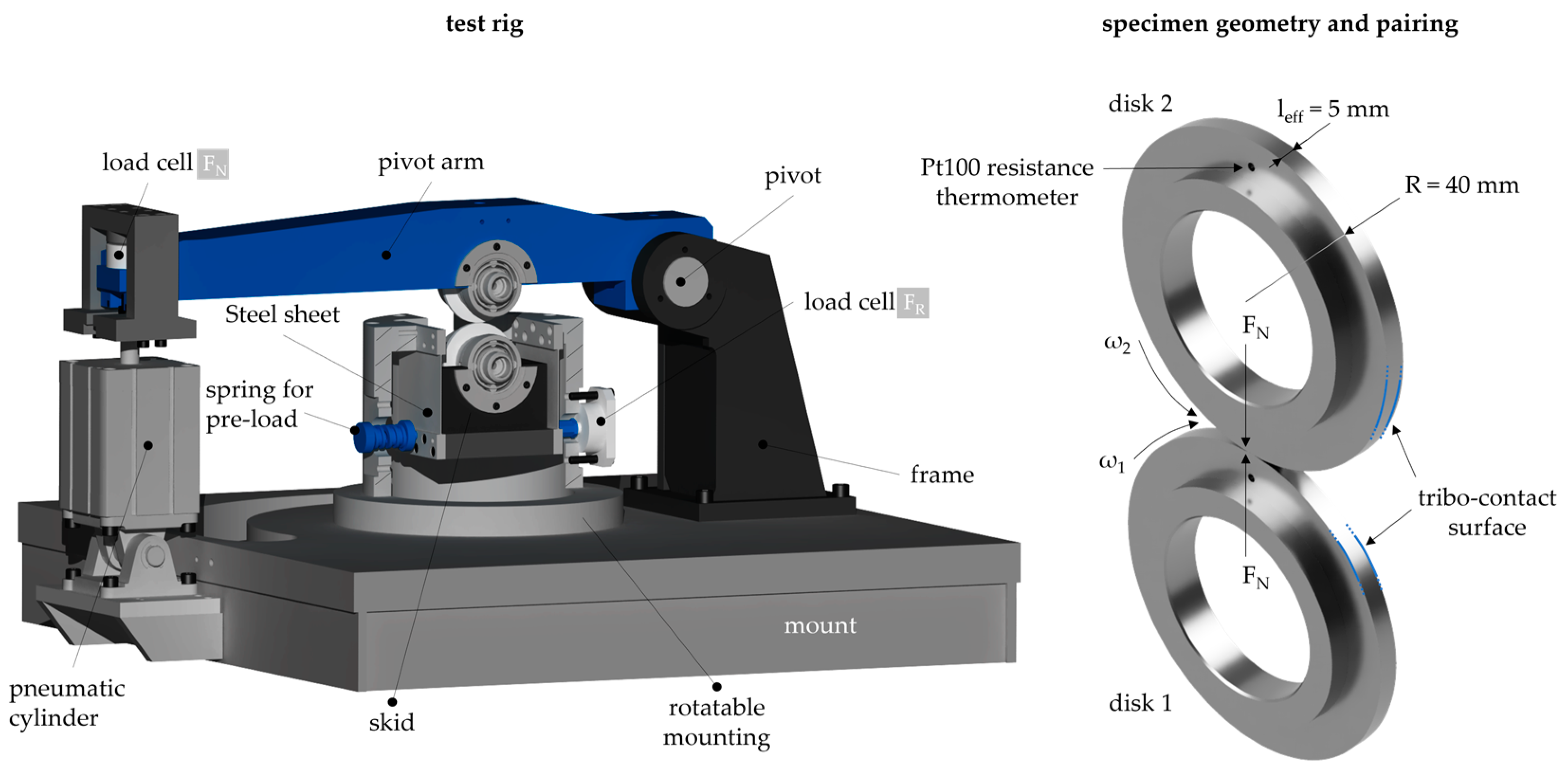
The specimen geometry is shown in Figure 1. The materials used are machined from a cylindrical blank to the target geometry for test purposes. The rolling-sliding contact is formed by the contact of two specially machined cylindrical disks of width leff = 5 mm and radius R = 40 mm (see Section 2.2 and Section 2.3). Based on reference surfaces in a longitudinally ground state with a parallel relative orientation to the running direction, various surface finishes (see surface images made with a Leica M205A from Leica Microsystems GmbH (Wetzlar, Germany) encoded stereo microscope in Table 2) are tested to investigate the influence of the surface on the self-lubricating EHL tribosystem. To consider the transfer to gear contacts in particular, axially ground disks are considered, as they represent the characteristic surface structure of a gear contact with conventionally ground tooth flanks with a surface structure perpendicular to the rolling-sliding direction. The arithmetic mean roughness Ra of the surface variants used is ≤0.25 µm for longitudinally and axially ground and non-finished at sinterpni, ≤0.10 µm for superfinished, and ≤0.01 µm for polished. Surface roughness measurements were performed using the profile method according to DIN EN ISO 13565 1-3 [40], measured with a length of Lt = 4.0 mm transversely to the current surface structure orientation and a cut-off wavelength of λc = 0.8 mm.
For self-lubrication tests, the sintered specimens were impregnated with oil using a pressure impregnation device (see [25]). The theoretical maximum impregnation quantity of a component is mmax ≈ 2 g and can be determined according to [25] from the porosity volume Vpor and the density of the designated oil ρoil = 0.849 g/cm3. Vpor is set at approximately 10% of the specimen volume Vspe = 24.2 cm3 through a validated manufacturing process (see Equations (1) and (2)). The impregnability of sintered components depends mainly on the porosity distribution inside the material and on the surface, the radius of the pore channels (equivalent to capillaries), the oil properties like viscosity, and the environmental conditions, e.g., process pressure during impregnation and temperature [41,42]. Since the pore network is randomly distributed and, according to Lados et al. [43], there may be isolated or hard-to-reach pores, the measured impregnation quantity moil is lower than mmax. The impregnation amount moil of all specimens is consistently lower than the theoretically possible impregnation amount mmax, ranging from moil = 1.501 g to = 1.863 g. The average oil impregnation amount across all tests is m ¯ oil = 1.671 g, corresponding to an impregnation degree of χimp ≈ 75%. Prior to weighing, the oil-impregnated specimens are cleaned with a compressed air pistol and dry tissues for the surfaces, as well as cotton swabs for the small bore of the Pt100 and for sharp edges.
Vpor = 0.1·Vspe
mmax = Vpor·ρoil
The test oil PAO100+PD used is a synthetic oil based on polyalphaolefin. It is a fully formulated oil of the ISO VG 100 class with a plastic deformation (PD) additive. The PD additives belong to the class of friction modifiers, which provide solid friction-reducing properties [44] through the tribo-induced reaction of additives with metallic surfaces. The oil data can be found in Table 3.

2.2. Test Rig

The experimental tests in this study were conducted using a twin-disk tribometer, which was also used by Ebner et al. (e.g., [23,25]) to investigate self-lubricating rolling-sliding contacts. Figure 2 shows a schematic of the mechanical configuration of the twin-disk tribometer. The description and formulations presented here are based on the publications of Ebner et al. [23] and Lohner et al. [44].
A normal force FN is applied to the disk contact by a pneumatic cylinder mounted at the end of a pivot arm. The lower disk is mounted in a skid that is attached to the frame by thin steel sheets. The skid is laterally supported by a load cell, which measures the frictional force FR in the disk contact as a reaction force of the operating conditions in the contact. The maximum load that can be applied on the disk contact is FN = 16 kN, resulting in individual pressure depending on the disk geometry and material. The maximum sum velocity is vΣ = 12 m/s. In this study, the upper disk (v2) rotates at a speed that is either the same or faster than the lower disk (v1), both of which rotate with a speed between 2 m/s and 8 m/s, depending on the test method (see Section 2.3). Based on the considered normal loads, the calculated Hertzian pressure pH in the disk contact is between 600 N/mm2 and 1.043 N/mm2. Within this study, the upper disk (v2) rotates at a faster speed than the lower disk (v1). The measurands are the normal force (FN), the frictional force (FR), the surface velocities of the lower and upper disk (v1 and v2) derived from the measured shaft speeds, and the bulk temperature (ϑM) of the upper test disk. ϑM is measured 5 mm below the disk surface using a Pt100 resistance temperature sensor, whose signal is transmitted from the rotating shafts via a mercury rotary signal transmitter and whose signal is transformed to a voltage signal in a Wheatstone Bridge after the transmitter. The location of the Pt100 sensor is selected as a compromise in order to obtain the temperature of the surface region as closely as possible, but also to ensure that there is sufficient distance between the sensor and the surface to prevent any interference with the contact stiffness and material strength when the disk is loaded. For evaluation, the bulk temperature measurement can be utilized to determine the level of dissipated energy and, thus, the frictional behavior of the tribosystem. Before each test, the contact pattern is carefully evaluated to ensure an evenly distributed load during the line contact of the disks, and any misalignment is mechanically corrected. To analyze the frictional behavior, the coefficient of friction (CoF) µ is determined from the measured friction force FR and normal force FN at the disk contact. According to Vojacek [46], the considered twin-disk tribometer has an accuracy for measuring µ of Δμ = 0.0025.
v = v1 + v2
s = ((v1 − v2)/v1)·100% with v1 < v2
µ = FR/FN
For a comparative test with external lubrication, an injection-lubrication unit is used. Thereby, the PAO100+PD oil is injected directly into the contact inlet with a volume flow rate of V ˙ = 1.5 L/min at ambient oil temperature (ϑoil = 25 °C) without any temperature regulation. For all measurements, the disk pair of a longitudinally ground, oil-impregnated sinterref disk with a longitudinally ground steek disk was established as the reference system. The experimental procedure outlined in Section 2.3 also includes other material–surface combinations to evaluate the influence of lubrication methods, material pairing, solid lubricant addition, and surface condition.

2.3. Test Method

The test method involves two steps under line contact conditions at the twin-disk tribometer (see Section 2.2), first starting with measuring friction curves of self-lubricating oil-impregnated sinter material and surface combinations compared to conventional injection lubrication, followed by long-term operation tests to evaluate the operating stability for stationary operating systems.

2.3.1. Friction Curves

For all tests, two new disk pairs with identical specifications are used. Prior to each test under self-lubrication, an initial oil volume of Vinit = 0.02 mL is applied to the dry tissue-cleaned contact surfaces to prevent initial damage during running-in. The measurements with injection lubrication are carried out with an initial oil temperature at ϑoil = 25 °C. All measurements are started at disk bulk temperatures ϑM ≈ ϑambient with a running-in of t = 60 s without an imposed pressure pH < 500 N/mm2 at moderate speed vΣ = 1 m/s and s = 2%. While testing, termination criteria are used to detect possible failures of a disk pair. These criteria are a bulk temperature ϑM greater than the critical bulk temperature ϑcrit > 140 °C or a CoF µ greater than the critical CoF µcrit > 0.12. Light microscopy images of the specimen surfaces are captured before and after the tests to evaluate the lubricating effect and the corresponding surface alteration. The disk pair of a longitudinally ground sinterref disk impregnated with the PAO100 with a longitudinally ground steel disk was established as the reference tribosystem for all measurements.
The friction curves are measured at operating points with a constant pressure of pH = 600 N/mm2 and different sum velocities v = {2; 4; 8} m/s. Each measurement at a sum velocity is made at discrete, increasing slip ratio s = {0; 2; 5; 10; 20; 30; 40; 50}%. The measurements with each disk pair are repeated once, with the 2nd measurement taken without re-impregnation of the sinter disk with oil. The repeatability of the two measurements is also analyzed to investigate the difference in the tribological behavior of a variant. Therefore, a repetition test is performed with a 2nd new disk pair, and both initial and subsequent measurements are made. Each operating point on the friction curve is maintained until quasi-stationary operating conditions are reached. An operating point is considered quasi-stationary when the bulk temperature difference ΔϑM remains within ΔϑM < 1 K for a period of t = 60 s. If a stationary operating condition is achieved, the average of the measurement data from the last t = 30 s is used. To evaluate the tribological behavior, µ as well as ϑM is plotted for each sum velocity vΣ at each prevailing slip ratio s. The measurements are started with the lowest sum velocity vΣ, starting with pure rolling at s = 0% at disk bulk temperatures ϑM close to ϑambient. Then, as the system reaches a stationary operating point, the slip ratio s is gradually increased. The friction curve for the next higher sum velocity vΣ is run after cooling the system back to ϑambient. The procedure is continued until all operating points have been investigated or until a termination criterion is reached. To achieve the objectives of this study, the experiments are performed sequentially with the following structure:
  • Demonstration of the functionality of self-lubricating rolling-sliding contacts across a wide range of operating points and comparison with injection-lubricated rolling-sliding contacts.
  • Determination of the tribologically optimal number of oil-impregnated elements in a self-lubricating rolling-sliding contact.
  • Investigation of the influence of surface condition and finish on self-lubricating rolling-sliding contacts.

2.3.2. Long-Term Tests

In the long-term operation tests, constant operating points are maintained. Hereafter referred to as the reference operating conditions, the operating point at a pressure of pH = 1043 N/mm2, a sum velocity of v = 4 m/s, and slip ratio of s = 20% is used for evaluation of the test results. The maximum duration of the tests is t = 48 h, which corresponds to a maximum load cycle number N2 ≈ 1.2 m on the faster rotating disk, provided that the automatic shutdown mechanism does not terminate the test prematurely due to reaching the termination criteria ϑcrit or µcrit. The repeatability of the long-term test results is indicated by the maximum difference of µ or N2 of the 1st and a repetition test performed with a 2nd new disk pair. To further investigate the study’s objectives, the long-term operating tests are conducted as follows:
  • Demonstration of long-term durability of self-lubricating contacts and comparison with injection-lubricated contacts.
  • Investigation of the influence of surface finish on the frictional and stress behavior in self-lubricating contacts.
  • Investigation of the improvement of the frictional behavior in self-lubricating contacts through solid lubricant additives in the sinter material.
  • Determination of the performance of self-lubricating contacts under higher load and speed.
  • Evaluation of the transferability to gear applications with typical tooth flank surfaces.
The measurements of each variant are examined immediately after the running-in. The test run is conducted intermittently in order to enhance the detection of surface alterations of the upper disk after a defined number of load cycles N2, using the Infinite Focus Sensor R25 from Alicona Imaging GmbH (Raaba, Austria), an optical measuring device based on the principle of focus variation for high-resolution surface imaging. The number of load cycles between two surface measurements is shorter at the beginning of the tests to document the running-in-like process of the first load cycles and increases after each measurement. An overview of the measurement intervals, expressed in terms of load cycle numbers and the corresponding times in hours, is presented in Table 4. During the intermittent measurement intervention, the system is interrupted for t < 5 min to prevent excessive cooling of the bulk temperature ϑM. The surface measurement of the upper disk captures individual areas in the shape of a square with an edge length of a = 1 mm and a 20-fold magnification to analyze the local surface condition. To obtain a global qualitative impression of surface alteration across the entire disk width from the composite local images, six overlapping surface images are taken along the direction of the cleaned area from one disk edge to the other. In this study, the surface image in the middle of the upper disk width is evaluated. Moreover, an expert qualitatively evaluated a surface area in the middle of the upper disk width using the optical appearance of pores in 2D images and the matching geometrical hole-like shape of pores in 3D topography measurements.
Each test run is evaluated by its levels and differences of friction µ and bulk temperature ϑM as well as its operating behavior coefficient Ξ according to Ebner [25]. The operating behavior coefficient Ξ is calculated by the division of the load cycles during the longest test sequence, with a maximum difference of the minimum and maximum of µ being smaller than Δµ < 0.005, and the load cycles for the whole lifetime of the disk pair. An operating behavior is defined as unstable when the load cycle of the upper disk for the whole lifetime is N2 < 0.25 M, as metastable when N2 > 0.25 M and Ξ < 0.40, and stable when N2 > 0.25 M and Ξ > 0.40.

3. Results

In the following section, first, the friction curves and, second, the long-term operation tests with applicability promising disk pairs are shown.

3.1. Friction Curve Tests

At first, the functionality of self-lubricating rolling-sliding contacts with oil-impregnated sinter material across a wide range of operating points is shown and compared to an injection-lubricated pure steel contact. Further on, the tribologically optimal number of oil-impregnated sinter disks in a self-lubricating rolling-sliding contact and the influence of surface condition are evaluated.

3.1.1. Demonstration of Self-Lubricating Rolling-Sliding Contacts and Comparison with Injection-Lubricated Rolling-Sliding Contacts

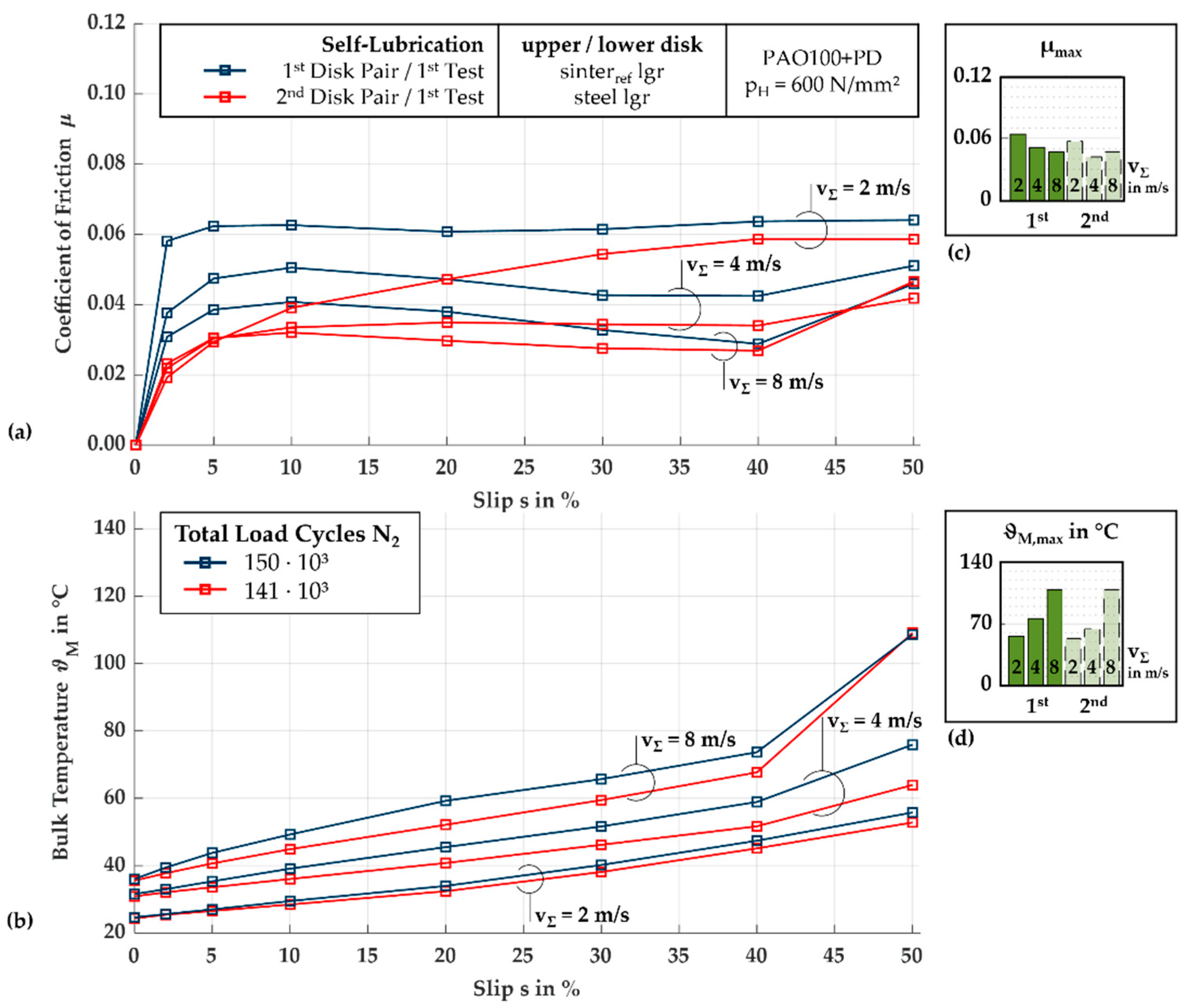
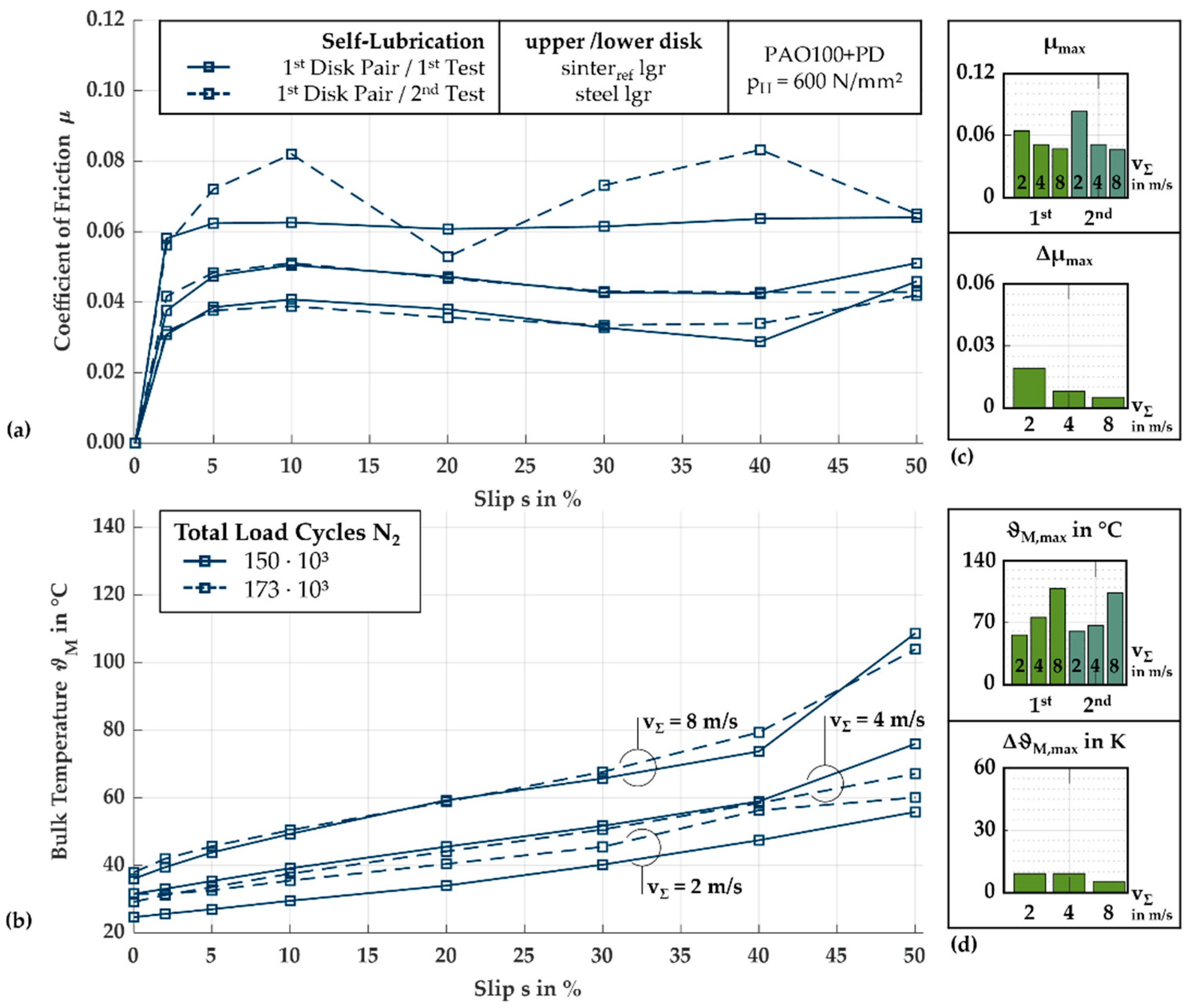
Figure 3a shows the measured friction curves of the reference disk pair with a longitudinally ground, oil-impregnated sinterref disk and a longitudinally ground steel disk under self-lubrication. Additionally, the maximum values µmax of each curve are shown in a bar diagram. The reference disk pair can be evaluated at all operating points as it did not exceed the termination criteria µcrit or ϑcrit during the tests. The measurements with the 1st and the 2nd disk pair both show the same trend: µ decreases with increasing vΣ. The friction curves of the 1st disk pair increase steadily within the first three measured slip ratios of s ≤ 5% and maintain a plateau at vΣ = 2 m/s over the remaining slip ratios at approximately µ ≈ 0.064. At vΣ = 4 m/s and 8 m/s, the CoF curves decrease again after reaching their respective local maxima at s = 10%, before increasing again at the highest slip ratio at s = 50% to the global maximum µmax = 0.051 and 0.047, respectively. The friction curves of the tests with the 2nd disk pair are at a continuously lower level compared to the CoFs of the 1st disk pair, with plateau-like curves at vΣ = 4 m/s and 8 m/s, reaching µmax = 0.042 and 0.047 at the highest slip ratio, respectively. Figure 3b shows the measured bulk temperature curves and the maximum values ϑM,max, which correspond to the increasing frictional power depending on the sum velocity, so that the levels of the bulk temperature are at vΣ = 2 m/s at the lowest, at 4 m/s at the middle, and at 8 m/s at the highest level. Within the respective sum velocities, the bulk temperature also increases with increasing slip ratio. In the bulk temperature curves, the temperatures of the 1st disk pair are higher than the temperatures of the 2nd disk pair. Specifically, the bulk temperature maxima of the 1st disk pair are ϑM,max = 56 °C, 76 °C, and 109 °C, while with the 2nd disk pair they are 53 °C, 64 °C, and 109 °C. Figure 4a shows the measured friction curves of the 1st and 2nd test with the 1st disk pair, which was re-run in the 2nd test after the 1st test without re-impregnation. Additionally, the maximum difference of µ between the 1st and the 2nd test is shown for each sum velocity. As for the 1st test, every operating point of the 2nd test can be evaluated, because no termination criteria were reached. The friction curve of the 2nd test at vΣ = 2 m/s increases with increasing slip ratio up to s ≤ 10% to a higher level than in the 1st test and, at s = 10%, reaches a local maximum for µ. However, with increasing slip ratio up to s ≤ 20%, µ decreases before increasing again to µmax = 0.083 at s = 40%. At the highest slip ratio s = 50%, µ decreases again. However, the friction curves of the 2nd test at sum velocities of vΣ = 4 m/s and 8 m/s follow a similar trend as the 1st test, with smaller increases in the curves up to the highest slip ratio at s = 50%. The global maxima of the curves at vΣ = 4 m/s and 8 m/s are µmax = 0.051 and 0.046, respectively. Additionally, Figure 4b shows the bulk temperature curves ϑM and the maximum values ϑM,max of the 1st and 2nd test with the 1st disk pair. The curves of both tests are very similar at vΣ = 8 m/s. At a velocity of 4 m/s, minimal temperature differences between the 1st and 2nd test are observed over most of the range of slip ratio variation, with slightly lower temperatures of the 2nd test at the highest level of slip ratio at s = 50%. In comparison, at vΣ = 2 m/s, higher bulk temperatures are measured at the 2nd test over the entire range of slip ratio variation. The maximum bulk temperatures of the 2nd test recorded for vΣ = 2 m/s, 4 m/s, and 8 m/s are ϑM = 60 °C, 67 °C, and 104 °C, respectively.
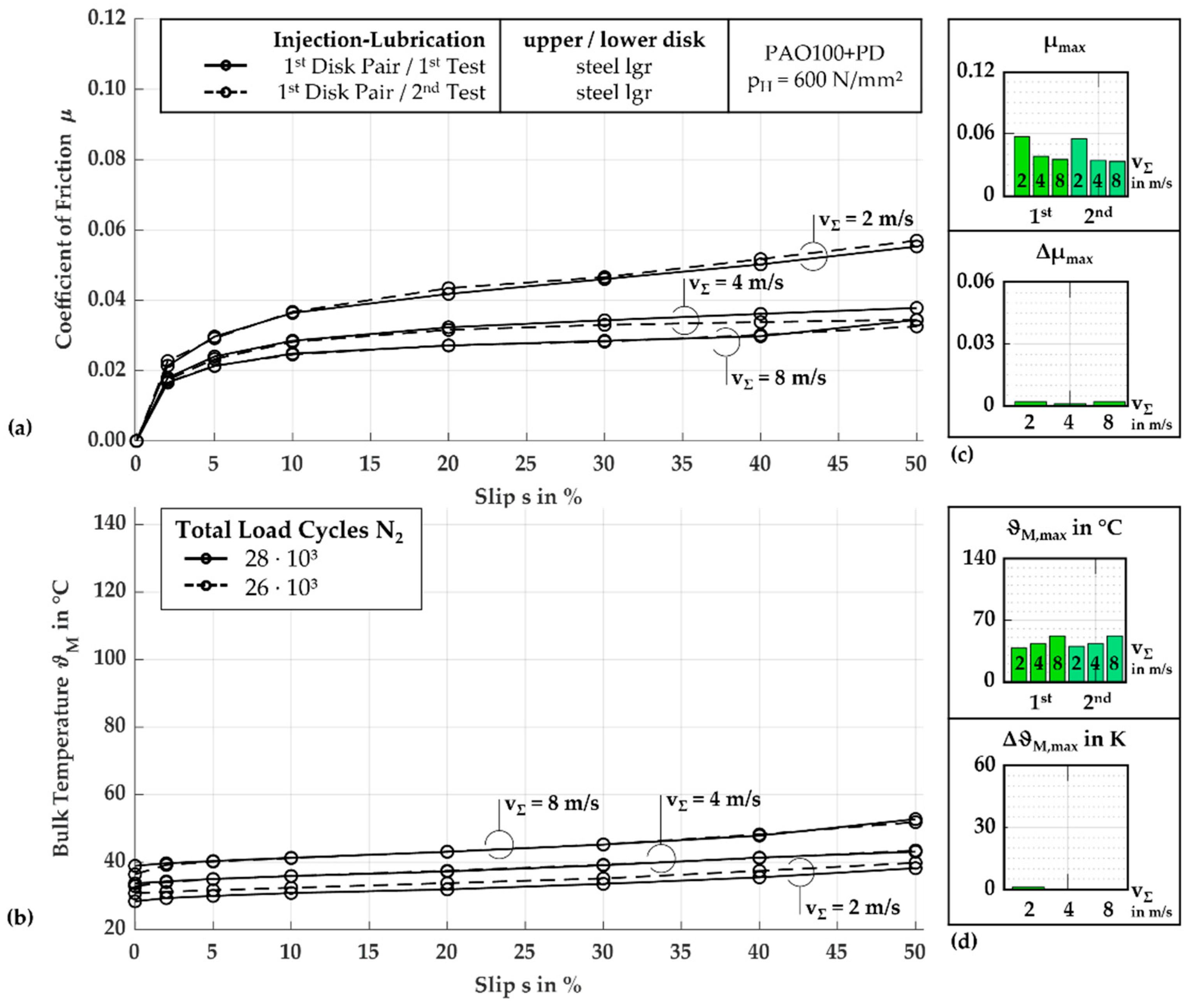
Figure 5a shows the measured friction curves of the 1st and 2nd test with the 1st disk pair with two longitudinally ground steel disks under injection lubrication. The friction curves initially increase with larger gradients over the slip ratios of s = 2–5%, then exhibit a smaller increase. The maximum coefficients of friction are µmax = 0.057, 0.038, and 0.035 in the 1st test run and µmax = 0.058, 0.034, and 0.033 in the 2nd test run. Figure 5b shows the bulk temperature curves of both tests, the 1st and 2nd test with longitudinally ground steel disks under injection lubrication, correlating to the curves shown in Figure 5a. The bulk temperature differences between the sum velocities remain largely constant over the slip ratios, with almost constant temperature differences. The 2nd test at vΣ = 2 m/s resulted in slightly higher bulk temperatures, approximately ΔϑM = +2 K higher than those of the 1st test. The maximum bulk temperatures at vΣ = 2 m/s, 4 m/s, and 8 m/s are ϑM,max = 38 °C, 43 °C, and 52 °C in the 1st test and 40 °C, 43 °C, and 52 °C in the 2nd test.

3.1.2. Determination of the Tribologically Optimal Number of Oil-Impregnated Sinter Elements in Self-Lubricating Rolling-Sliding Contacts

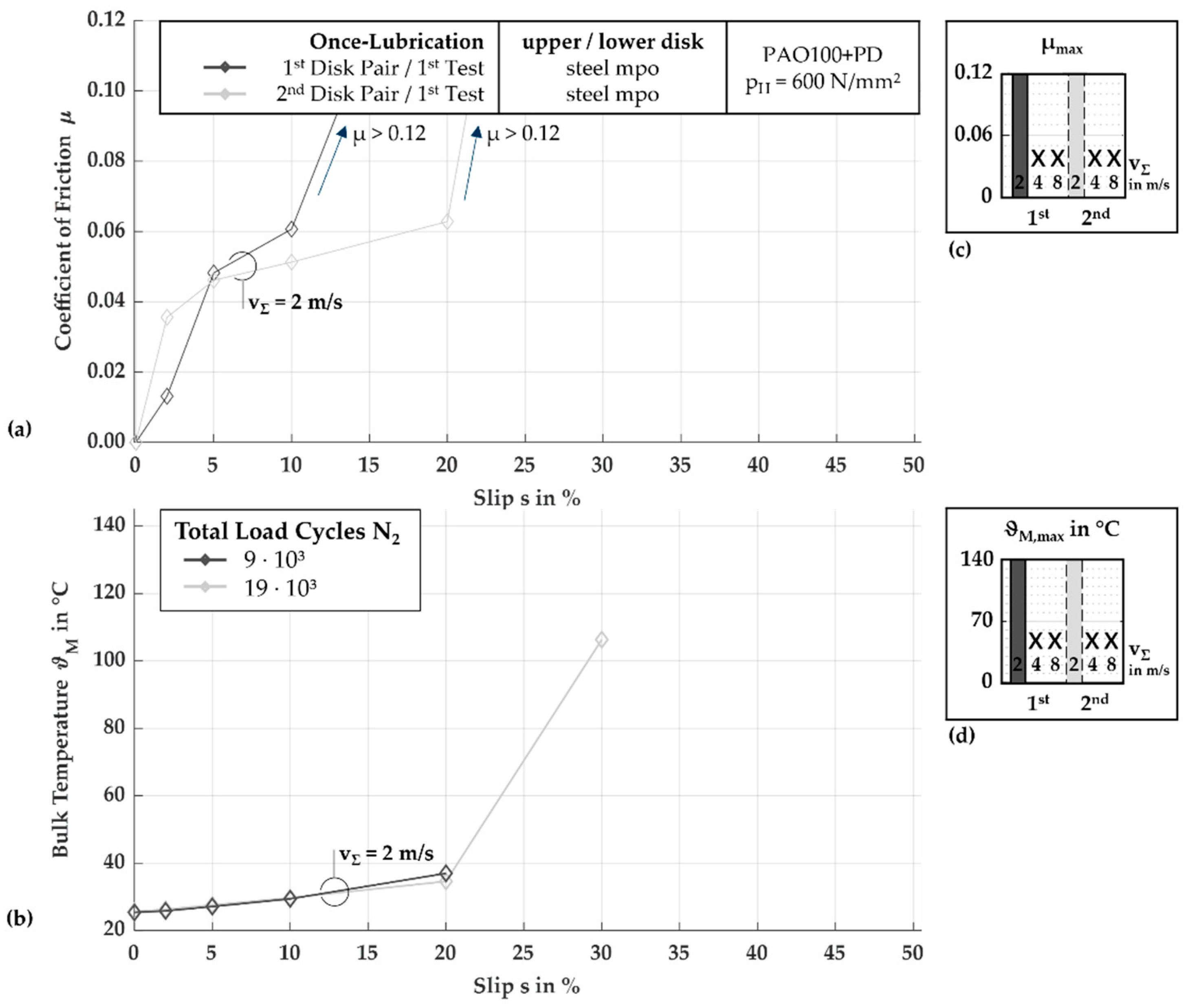
Figure 6a shows the measured friction curves of the 1st tests of two polished steel disk pairs, each lubricated only once with Vinit. Because of an expected harsh mixed lubrication regime in once-lubricated EHL tribosystems due to the low amount of prevailing oil, the steel disks were mechanically polished to reduce the influence of the surface roughness on the relative lubricant film thickness and thus improve the expected friction to be better performing compared to once-lubricated EHL tribosystems with longitudinally ground surfaces. Due to the termination criterion of µ > 0.12 reached at vΣ = 2 m/s with s = 20% or 30%, both tests can only be evaluated for a few operating points. Figure 6b shows the bulk temperature curves of both tests correlating to Figure 6a, which both show increasing ϑM with increasing slip ratios. Repeating the test with the 1st or the 2nd disk pair is not possible because of surface damage.
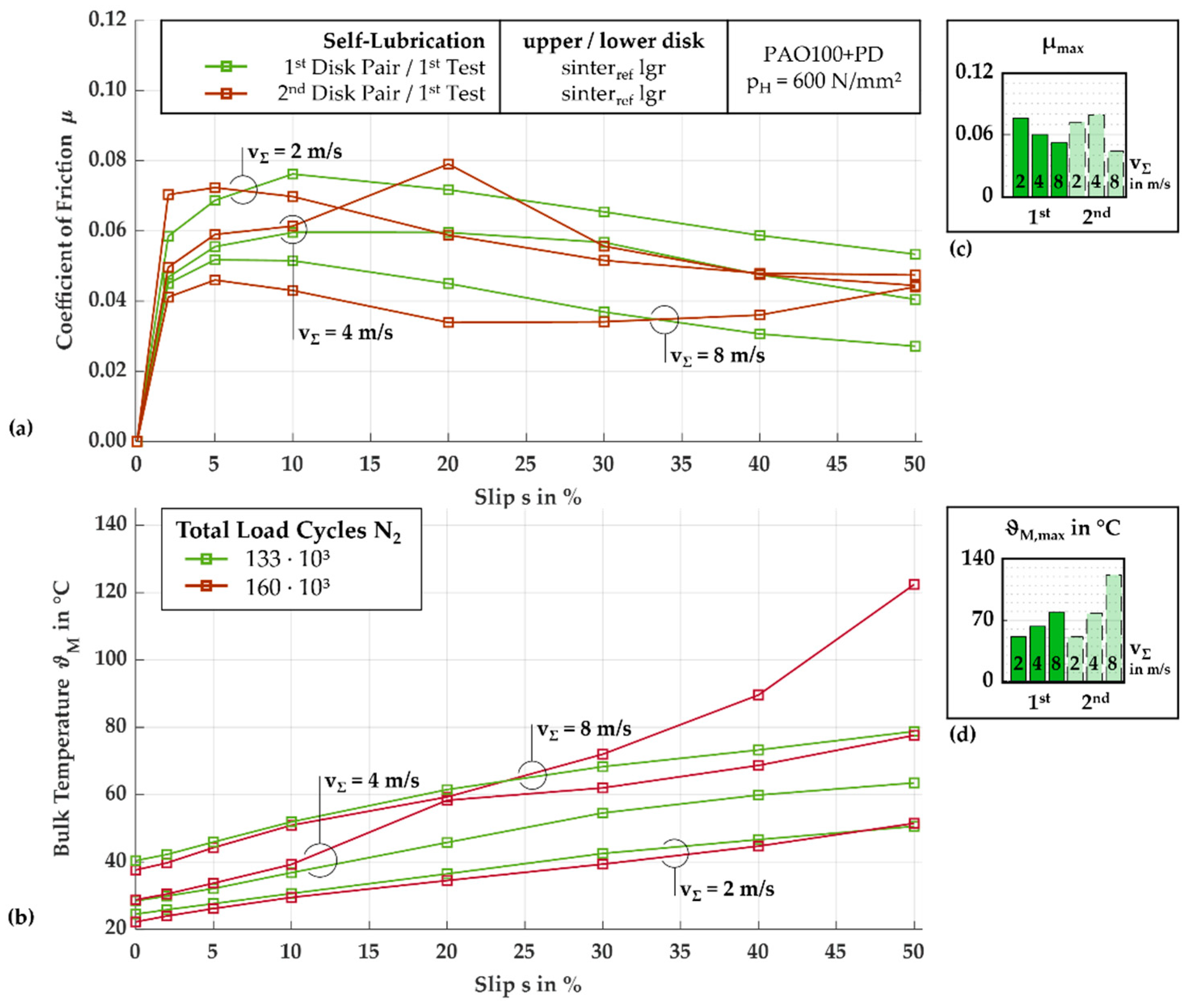
Figure 7a shows the measured friction curves and maxima µmax of the 1st tests of two disk pairs, each with two longitudinally ground, oil-impregnated sinterref disks. The trends observed with the 1st disk pair are clearly related to the sum velocity. The data shows that µ gradually decreases with increasing vΣ, with all curves starting with a steep gradient of µ within the initial slip ratios, then decreasing after reaching a global maximum µmax. For instance, at vΣ = 2 m/s, the global maximum CoF is µmax = 0.076 at s = 10%. Similarly, at vΣ = 4 m/s, the global maximum of CoF is µmax = 0.060 at s = 20%, and at vΣ = 8 m/s, it is µmax = 0.052 at s = 5%. The bulk temperatures shown together with ϑM,max in Figure 7b appear to increase as the sum velocity increases, with relatively constant increases for each sum velocity. At vΣ = 2 m/s, the maximum bulk temperature is ϑM,max = 51 °C, at 4 m/s it is 63 °C, and at 8 m/s it is 79 °C. The 1st test with a 2nd disk pair of the same specification shows trends that follow less clearly the previous patterns of sum velocity and slip ratio variation (see Figure 7a,b). In particular, at vΣ = 2 m/s, the coefficient of friction is initially higher at s ≤ 5% and reaches a maximum of µmax = 0.072 at s = 5%, before decreasing at s ≤ 40% and remaining approximately constant up to s = 50%. At vΣ = 4 m/s, the coefficient of friction initially follows the trend of the 1st disk pair before a peak of µmax = 0.079 at s = 20%, which is higher than the maximum at vΣ = 2 m/s, and then declining to a level comparable to the 1st test. The friction curve at vΣ = 8 m/s lies, as typically expected, at the lowest level of the sum velocities within the tests of one disk pair. The curve reaches a local maximum at s = 5%, before decreasing again to s = 20%, then increasing significantly and reaching the global maximum at s = 50% with µmax = 0.044. The correlation between the bulk temperatures and the coefficient of friction curves is evident. The curve at vΣ = 2 m/s is the lowest with ϑM,max = 51 °C, the curve at vΣ = 4 m/s is higher with ϑM,max = 78 °C and shows a significant increase at the peak of the CoF at s = 20%, and the curve at vΣ = 8 m/s is comparatively the highest, increasing significantly from the slip ratio s = 20% until it reaches a maximum with ϑM,max = 122 °C, significantly higher than that of the 1st test.
Figure 8a shows the friction curves and maxima µmax measured with the 1st and 2nd test of the 1st disk pair of two longitudinally ground, oil-impregnated sinterref disks. The 2nd test of the 1st disk pair can be evaluated at all operating points but shows significantly higher µ soon after initially lower values at all three sum velocities investigated, reaching near the termination criterion at vΣ = 2 m/s with µmax ≈ 0.12 and increasing to similar values at vΣ = 4 m/s and 8 m/s, with µmax = 0.063 and 0.062, respectively. Figure 8b shows the bulk temperature curves and maxima ϑM,max measured during the 2nd test of the disk pair shown in Figure 8a. The bulk temperatures initially start at slightly higher levels before increasing along with the significant increases in the coefficients of friction, all reaching the bulk temperature maxima at s = 50% at vΣ = 2 m/s, 4 m/s, and 8 m/s, at ϑM,max = 66 °C, 90 °C, and 136 °C, respectively.

3.1.3. Investigation of the Influence of Surface Finish on Self-Lubricating Rolling-Sliding Contacts

The investigation of the surface influence on the tribological behavior of self-lubricating, oil-impregnated sintered rolling-sliding contacts is carried out systematically. Initially, a mechanically polished steel disk surface is paired with a longitudinally ground, oil-impregnated sinterref disk. Subsequently, a mechanically polished steel disk is paired with different surface variants of the oil-impregnated sinterref disk. Therefore, the surface of the sinterref disk is investigated in different conditions for the reference material, including superfinished and mechanically polished surfaces. Furthermore, the influence of a plasma-nitrided sinterpni disk with high hardness is investigated.
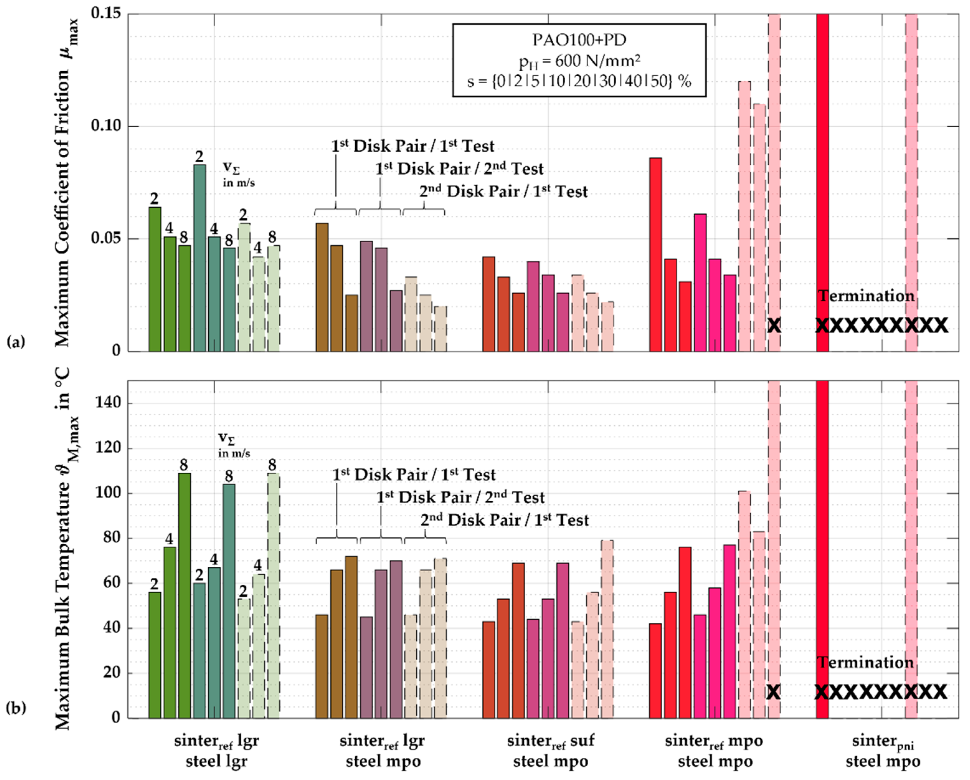
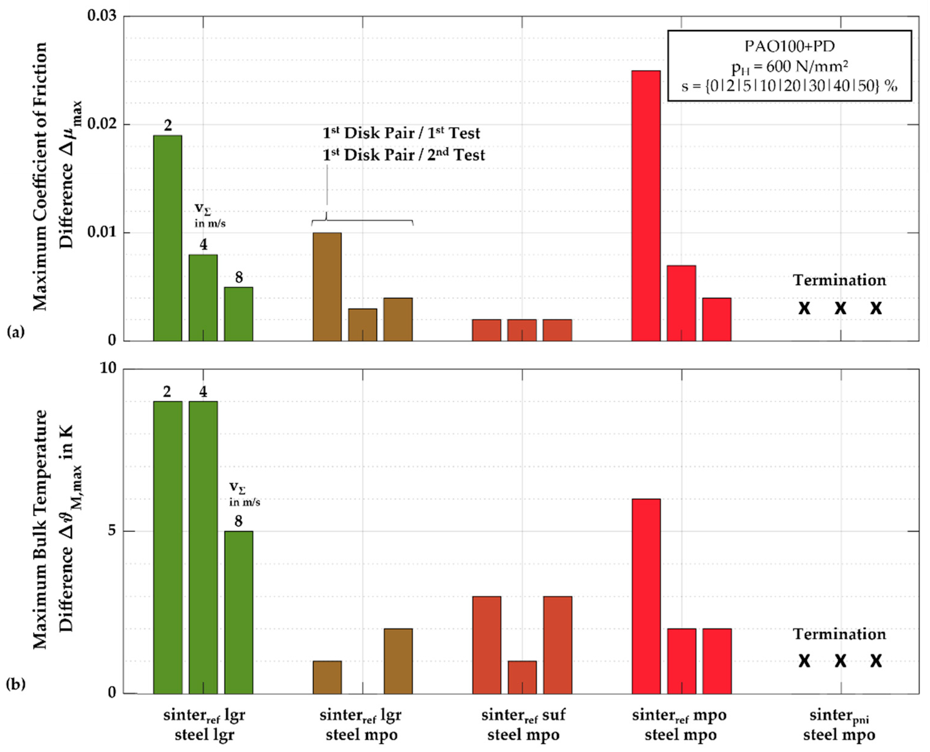
Figure 9a,b summarize the evaluated maximum µmax and ϑM,max from measured friction and bulk temperature curves of the two test runs with the 1st disk pair (1st and 2nd test), as well as the 1st test with a 2nd disk pair. Additionally, Figure 10a,b show the maximum difference of the friction curves Δµmax and of the bulk temperature curves ΔϑM,max of the 1st and 2nd test with the 1st disk pair. The results obtained with the reference disk pair with a longitudinally ground steel disk and a longitudinally ground, oil-impregnated sinterref disk are also included for comparison.
The surface variation of the steel disk from a longitudinally ground to a polished condition shows improved tribological behavior compared to the reference measurements with both disk surfaces in a longitudinally ground condition, indicated by low levels of µmax and ϑM,max in the 1st test runs of the 1st and 2nd disk pair and especially with the 2nd disk pair, with µmax = {0.033, 0.025, 0.020} and ϑM,max = {46, 66, 71} °C. There was good repeatability of the 1st test with the 1st disk pair through the 1st test with the 2nd disk pair, with very similar ϑM,max and smaller µmax at all vΣ (see Figure 9a,b), and a low maximum difference of Δµmax = 0.003 … 0.010 and ΔϑM,max ≤ 2 K between the 1st and 2nd test with the 1st disk pair (see Figure 10a,b).
Figure 11a and Figure 12a show the measured friction curves with disk pairs with mechanically polished steel and superfinished sinterref disk surfaces; the curves with a superfinished sinterref disk surface show, on one hand, a similar tribological beneficial trend to the curves with the mechanically polished steel disk surface, and on the other hand, the best tribological behavior compared to the other surface variants. Measurements taken with superfinished contact surfaces show µmax ≤ 0.042 for all tests with both disk pairs down to µmax ≤ 0.022 at vΣ = 8 m/s with the 2nd disk pair as well as a very good repeatability between the 1st tests with the 1st and 2nd disk pair, with slightly lower levels of µmax with the 2nd disk pair (see Figure 11a) and the least maximum difference Δµmax = 0.002 between the 1st and 2nd test with the same 1st disk pair (see Figure 12a). Figure 11b and Figure 12b additionally show the measured bulk temperature curves of the disk pairs with mechanically polished steel and superfinished sinterref disk surfaces. Overall, the levels of the maximum bulk temperature ϑM,max are the lowest compared to the tests with the other surface variants, with the lowest maximum bulk temperatures at the 1st test with the 2nd disk pair with ϑM,max = {43, 53, 69} °C. Comparing the 1st and 2nd test with the 1st disk pair, a low maximum difference of ΔϑM,max ≤ 3 K is shown.
In contrast, the tests with disk pairs with mechanically polished steel and sinterref disk surfaces show, at the 1st tests of the 1st and 2nd disk pair, initially at a sum velocity of vΣ = 2 m/s, high to very high CoF, with µmax = 0.086 and = 0.12 (see Figure 9a). During both test runs (1st and 2nd test) with the 1st disk pair, the friction curve levels decrease with increasing sum velocity, while the 2nd test shows a lower level of µmax at vΣ = 2 m/s and comparable levels of µmax at vΣ = 4 m/s and = 8 m/s. During the 1st test with the 2nd disk pair, the friction curve level first slightly decreases with an increasing sum velocity at vΣ = 4 m/s before leading to termination at the highest sum velocity at vΣ = 8 m/s. The bulk temperatures of the two tests with the 1st disk pair shown in Figure 9b are comparable to the bulk temperature levels with the disk pairs of a polished steel disk and ground sinter disk and show moderate to low maximum difference with ΔϑM,max ≤ 6 K. The bulk temperatures of the 1st test with the 2nd disk pair follow the trend of µ and, compared to the tests with the 1st disk pair, also start at a high level at vΣ = 2 m/s with ϑM,max = 101 °C, and decrease slightly to ϑM,max = 83 °C at vΣ = 4 m/s before thermally increasing at vΣ = 8 m/s. With the comparison of the tests of the two disk pairs with identical specifications, which can show both a good frictional behavior with a low to moderate difference of the maximum Δµmax ≤ 0.025 and ΔϑM,max ≤ 6 K between the 1st and 2nd test with one disk pair (see Figure 10a,b), and a non-functional behavior with another disk pair, a significantly worse repeatability of the tribological behavior of disk pairs with polished sinter disk surfaces is shown.
The tests with the disk pairs with a polished steel disk and a plasma-nitrided sinterpni disk with high hardness cannot be evaluated due to a failure within the initial sum velocity of vΣ = 2 m/s in the 1st tests of the 1st and 2nd disk pair. The failure is indicated by an acceleration detector, which causes the tribometer to stop immediately. An analysis of the sinterpni disk surfaces revealed delamination of the compound layer from the underlying diffusion layer.

3.1.4. Summary of the Friction Curve Tests

Table 5 summarizes the evaluated data of the friction curve tests (see Section 3.1.1, Section 3.1.2 and Section 3.1.3), including the total test duration N2 of each friction curve test of the two disk pairs.
The results of the friction curve tests were used to reduce the number of variants to the most promising disk pairs for long-term testing. As a result, the disk pair variants terminating after one test under self-lubrication with a mechanically polished sinterref disk as well as with a sinterpni disk are not considered for the long-term tests. The disk pair of two sinterref disks with its increased material preparation effort for oil impregnation by simultaneously increased friction and bulk temperature levels at all tests and increased differences of friction and bulk temperature between the 1st and 2nd test with the 1st disk pair are also not considered for the long-term tests.

3.2. Long-Term Tests

This section presents the results of the long-term tests with the selected material pairing and surface condition variants from Section 3.1. The operating behavior of the reference disk pair with a longitudinally ground steel and a longitudinally ground sinterref disk is compared to that of an injection-lubricated disk pair with two longitudinally ground steel disks. Furthermore, the influence of surface finish on the operating behavior during the long-term tests is examined, followed by an investigation of the influence of the solid lubricant for friction reduction in both once-lubricated and self-lubricating disk pairs. Also, the performance at higher loads is evaluated, and the functionality of gear-application-like surfaces on the disks is examined.

3.2.1. Demonstration of Long-Term Durability of Self-Lubricating Contacts and Comparison to Injection Lubrication

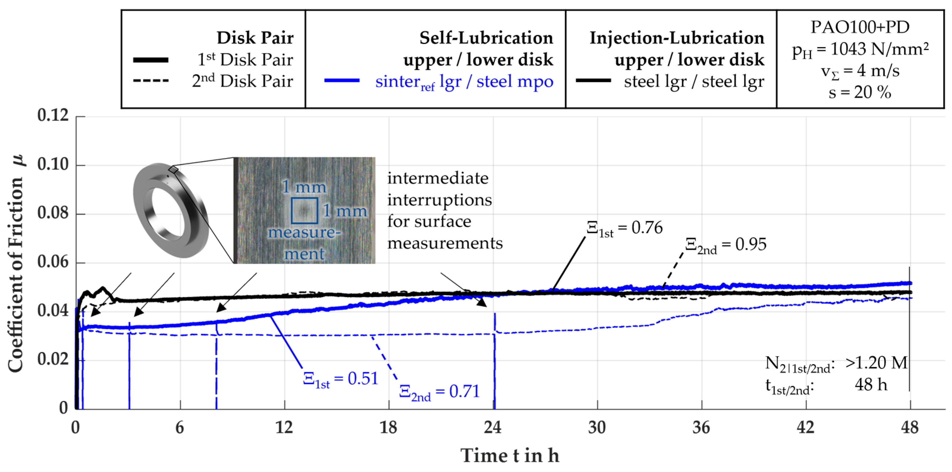
Figure 13 shows the measured friction curves and the calculated stability coefficients of the two long-term tests with a self-lubricating EHL tribosystem with a polished steel disk and an oil-impregnated ground sinterref disk as well as an EHL tribosystem with longitudinally ground steel disk pairs under injection lubrication without temperature regulation. Both the 1st and 2nd test of the injection-lubricated disk pair show for the whole test run of 48 h (i.e., N2|1st and N2|2nd > 1.20 M) very good stability according to Ebner [25], with Ξ = 0.95 and = 0.76. Initially, each of the curves starts with a coefficient of friction level of µ = 0.045 and exhibits the level for the main time of the test duration. In comparison, both tests with the self-lubricating EHL tribosystem start with a lower CoF of µ = 0.037. Then, the test with the 1st disk pair without intermediate interruptions for surface measurements increases steadily with a small gradient, passing the level of CoF of the injection-lubricated tribosystem after t ≈ 25 h and reaching µmax = 0.052. The determined stability coefficient is Ξ = 0.51 and indicates stable operating behavior. However, the test with the 2nd disk pair slightly decreases at the first section of the tests and is maintained at a comparably low level of µ = 0.035 for at least t ≈ 24 h, when the level slowly starts increasing to µmax = 0.045. The operating behavior of the 2nd disk pair can be classified as stable, as the determined stability coefficient is Ξ = 0.71. In addition to the comparable lower µ and the stable operating behavior, the EHL tribosystem under self-lubrication shows less repeatability because of the lower level of µ of the 2nd test, with Δµmax = 0.020, whereas both tests with the injection-lubricated EHL tribosystem show a difference of Δµmax = 0.005 from the beginning of the tests and a neglectable difference for the rest of the measurement time.
As there are intermediate interruptions for surface measurements, the following EHL tribosystem behavior after continuing the test has to be evaluated to verify the friction and bulk temperature trends deriving from the disk pair specifications and not from cool-down periods. At the intermittently interrupted test with the self-lubricating disk pair shown in Figure 13, one can see the very short peaks of CoF directly after re-starting the test and, after a few load cycles, the return of the friction curves to the previous level the moment before the interruption of the twin-disk tribometer. With the curves returning to the previous state before the interruption, the influence of the test interruptions on the trend of the tribosystem operating behavior can be assumed as negligible.

3.2.2. Investigation of the Influence of Surface Finish on the Frictional and Stress Behavior in Self-Lubricating Contacts

Figure 14a shows the measured friction curves and the calculated stability coefficients of the long-term tests with self-lubricating disk pairs with the reference EHL tribosystem of a longitudinally ground steel disk and a longitudinally ground oil-impregnated sinterref disk and surface variants of the disk pair with disk pairs of a mechanically polished steel disk and an oil-impregnated longitudinally ground as well as a mechanically polished sinterref disk. When varying the surface finish of the pairing disks in the self-lubricating EHL tribosystem, the trends of the measured friction during the long-term tests are comparable to the trends obtained at the friction curve tests, with no termination until the end of the 48 h test runs at N2|1st and N2|2nd > 1.20 M (see Figure 9 in Section 3.1.3). In nearly all tests, the disk pairs with at least one smoothed surface show lower levels of µ compared to the reference system with longitudinally ground surfaces, except in the 1st test with the disk pair of a mechanically polished steel disk and a longitudinally ground sinterref disk. When taking the pair of the polished steel disk and the superfinished sinterref disk evaluated as the best during the friction curve tests into account, the comparably very low level of µ ≤ 0.040 and the very stable operating behavior of both disk pairs with Ξ = 1.00 and = 0.69 as well as the good repeatability with Δµmax < 0.008 verify the trend of the best-performing self-lubricating EHL tribosystem. Further, the bulk temperatures ϑM measured during the long-term tests are shown in Figure 14b, in which every curve of ϑM correlates to the trend of µ evaluated, leading to the lowest ϑM measured with the disk pair of a mechanically polished steel disk and a superfinished sinterref disk. The short intermediate interruptions for surface measurements lead at all tests to a difference of the bulk temperature of ΔϑM,int ≤ 37.5 K while cooling down. In every test run, the offset ΔϑM,int is compensated at a few load cycles and has little significant influence on the further levels as well as trends of the bulk temperature curves and friction curves measured before the interruption.

3.2.3. Investigation of the Improvement of the Frictional Behavior in Self-Lubricating Contacts through Solid Lubricant Additives in the Sinter Material

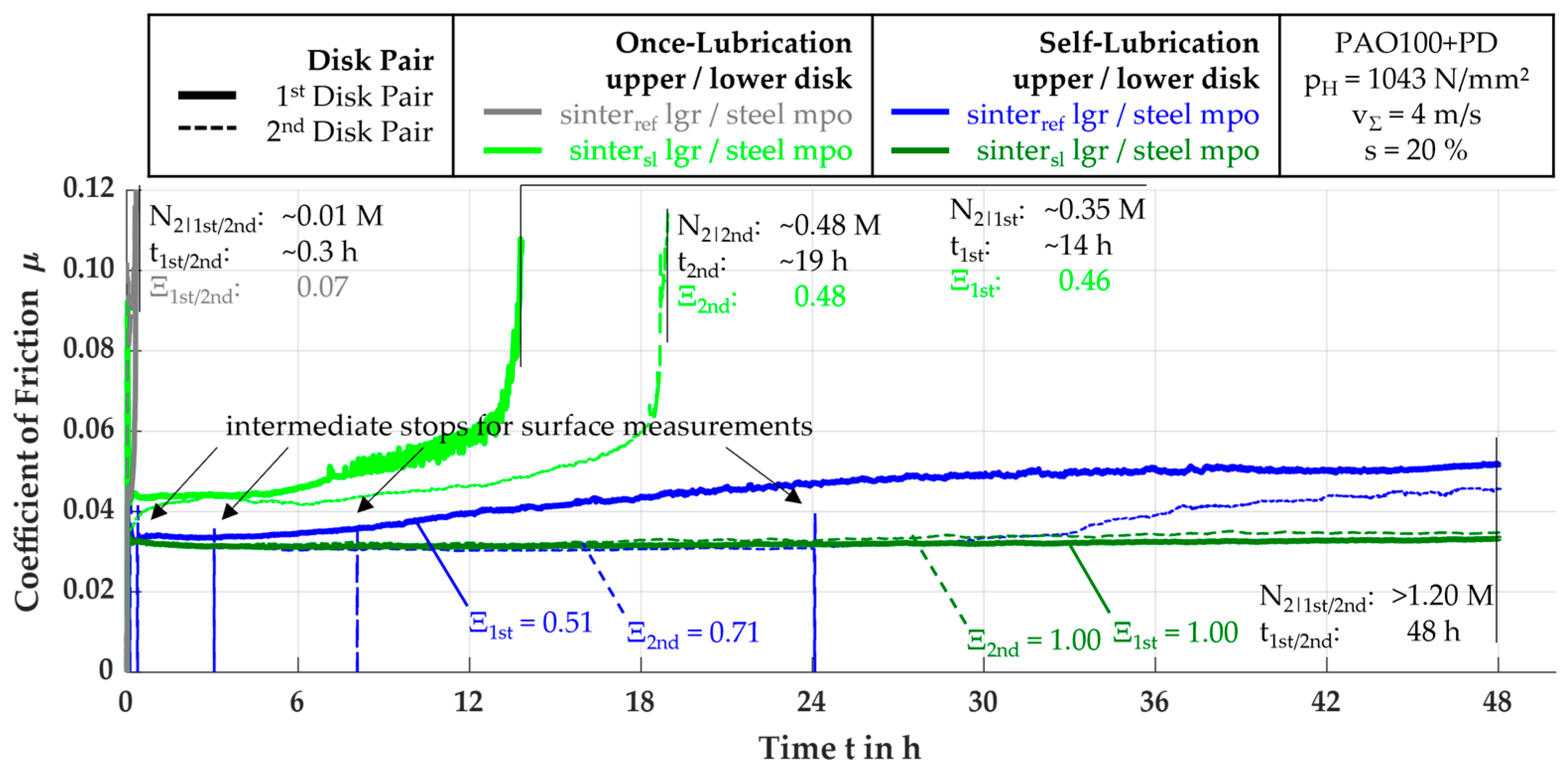
Additionally to the measurements made with the sinterref material, tests with an oil-impregnated and a non-impregnated solid lubricant alloyed sintersl material are made. Figure 15 shows the measured friction curves and the stability coefficients during long-term tests with disk pairs of a mechanically polished steel disk and variants of the longitudinally ground sinter disk in terms of a non-oil-impregnated sinterref or sintersl disk for investigations under once-lubrication as well as an oil-impregnated sinterref or sintersl disk for investigations under self-lubrication.
Both tests with the once-lubricated steel-sinterref disk pairs show unstable operating behavior with Ξ = 0.07, leading to termination after just a few load cycles of the upper disk. The operating behavior obtained with the once-lubricated EHL tribosystems with a non-oil-impregnated sintersl disk is characterized by an initial friction curve level of µ ≈ 0.044, which is slightly higher than the friction level of the EHL tribosystem with a disk pair of a mechanically polished steel disk and a longitudinally ground, oil-impregnated sinterref disk under self-lubrication. During the initial sequence of <7 h (i.e., N2|1st and N2|2nd < 0.15 M) stable operating behavior is obtained. After that, µ increases in the test with the 1st disk pair with a steep gradient and demonstrates unstable operating behavior, promptly reaching the termination criterion after t ≈ 14 h at N2|1st ≈ 0.35 M. The test with the 2nd disk pair reaches unstable operating behavior, and thus its termination limit is after a longer period of increasing µ, after t ≈ 19 h at N2|2nd < 0.50 M. When additionally impregnating the sintersl disk with PAO100+PD, the solid lubricant additive consistently results in low levels of µ over the whole measurement time. Additionally, it exhibits repeatably larger load cycle ranges without any increase in µ, thus demonstrating the most stable operating behavior with Ξ = 1.00. The difference between the tests with the two disk pairs of Δµmax < 0.002 is the lowest when compared to all other tests.

3.2.4. Determination of the Performance of Self-Lubricating Contacts under Higher Load and Speed

Based on the long-term tests under reference operating conditions, maximum load tests are carried out at both higher v and higher pH. The variation in kinematics is tested with the promising self-lubricating EHL tribosystems with a polished steel disk and, as the best-performing sinter material variant evaluated, a longitudinally ground sintersl disk. Figure 16 shows the friction curves of the long-term tests with disk pairs of a mechanically polished steel disk and a longitudinally ground sintersl disk under self-lubrication at v and pH, each at a higher level compared to the reference operating conditions shown in Section 3.2.1, Section 3.2.2 and Section 3.2.3.
When the total speed is increased to v = 8 m/s (equivalent to a maximum of N2|1st and N2|2nd > 2.4 M for a full 48 h test run), the tests with the 1st and 2nd steel–sintersl disk pair reach their termination limits at different times, after t ≈ 43 h at N2|1st ≈ 2.17 M and after t ≈ 17 h at N2|2nd ≈ 0.89 M due to exceeding ϑM,max = 140 °C. Due to the higher vΣ and, therefore, the sliding velocity, the measured CoF of µ ≈ 0.043 is comparably higher than at the lower sum velocity of vΣ = 4 m/s. Whereas the 1st disk pair shows stable operating behavior with Ξ = 1.00, the operating behavior of the earlier terminating 2nd disk pair is evaluated as metastable with Ξ = 0.18. The difference between the tests with the two disk pairs is Δµmax < 0.04. Nevertheless, the test with the 1st disk pair shows a 244% higher lifetime than the test with the 2nd disk pair.
At tests at higher pressure pH = 1200 N/mm2, the two tests with a steel–sintersl disk pair initially differ from each other more (Δµmax = 0.011) than after further test progression, which leads to a measured µ in both tests at the same level (Δµmax ≈ 0) of µ = 0.038. The overall trend shows initially metastable operating behavior with µ = 0.040, which changes to a more stable operating behavior with a decreasing µ after increasing load cycles, N. Although the frictional power is higher, both tests reach the measurement time limitation at N2|1st and N2|2nd > 1.2 M without termination.

3.2.5. Evaluation of the Functionality of Self-Lubrication with Tooth Flank Similar Surfaces

Figure 17 shows the friction curves measured during the long-term tests under self-lubrication with disk pairs of an axially ground steel disk and a sinterref as well as a sintersl material variant of an axially ground, oil-impregnated sinter disk. The axially ground surface structure orientation represents the typical surface structure of cylindrical gear tooth flank surfaces.
In both variants of the EHL tribosystem with axially ground sinterref and sintersl material, the measured friction curves of all tests are consistently higher than the measured friction curves of the tests with the reference EHL tribosystem with longitudinally ground surface structures. The two tests with the sinterref disk both terminate due to exceeding the upper limits of ϑM,max after different times with sequences of short-term stable, metastable, and unstable operating behavior, approximately after t ≈ 35 h at N2|1st ≈ 0.88 M and after t ≈ 10 h at N2|2nd ≈ 0.25 M of the upper disk. The test with the 1st disk pair shows stabilization of operating behavior after an initial increase in µ. This is demonstrated by the formation of plateaus in the measured friction curves. However, there is a brief decrease in µ after t > 9 h at N2|1st ≈ 0.20 M, followed by an increase of µ with stronger metastable operating behavior from t ≥ 10 h at N2|1st ≈ 0.22 M until the test run terminates, which leads to an overall stability coefficient of Ξ = 0.30, characterizing a metastable operating behavior, although the system is terminated. The test with the 2nd disk pair shows a continuous increase in µ and, with this, an overall stability coefficient of Ξ = 0.15, characterizing an unstable operating behavior. In both tests with the axially ground disk pair with a sintersl disk, the solid lubricant additive of sintersl proves advantageous. In both test runs, the measured levels of µ are lower compared to the tests with the axially ground disk pairs with a sinterref disk, resulting in both the 1st and the 2nd test lasting until the end of the designated test time of t = 48 h at N2|1st and N2|2nd > 1.2 M. Generally, a temporarily decreasing level of µ can be observed in both tests, which leads to the stability coefficients Ξ = 0.27 and = 0.56. During the 1st test only, the operating behavior changed from a stable to a metastable status, with rapidly increasing and then decreasing trends of µ starting from t ≈ 34 h at N2|1st ≈ 0.83 M, with the decreasing trend continuing and the experiment not having to be terminated.

3.2.6. Summary of the Long-Term Tests

Table 6 shows the evaluated data of the long-term tests conducted at the reference operating conditions (see Section 3.2.1, Section 3.2.2, Section 3.2.3 and Section 3.2.5) as well as at operating conditions at increased load and increased sum velocity (see Section 3.2.4). The lifetime reached by each disk pair is shown in percentage of the reached load cycles N2|1st and N2|2nd compared to the aimed load cycle N2|48h after t = 48 h. For the tests with vΣ = 4 m/s, the load cycles of a test without termination are N2|48h > 1.2 M, and for the tests with vΣ = 8 m/s, N2|48h > 2.4 M.
None of the disk pairs of the two disk pair variants tested under once-lubrication reach the aimed lifetime, whereas the disk pair with a sinterref disk shows a negligible lifetime with unstable operating conditions, and the disk pair with a sintersl disk shows a lifetime of minimum 29% to maximum 40% of the aimed lifetime with a stability coefficient of Ξ1st and Ξ2nd > 0.40, leading to a stable operating condition according to Ebner [25]. Further, seven of the eleven disk pair variants reach the aimed lifetime of N2|48h > 1.2 M and > 2.4 M after t = 48 h, even the disk pair tested at an increased applied load. All the disk pairs reaching the aimed lifetime operate in stable operating conditions, except the metastable operating 2nd disk pair with the both longitudinally ground sinterref and steel disks and the 1st disk pair with the both axially ground sintersl and steel disks. The lowest friction results from the disk pairs with a mechanically polished steel disk and a superfinished sinterref disk or a longitudinally ground sintersl disk, with µ ¯ 1st = 0.031 and µ ¯ 2nd = 0.036, and µ ¯ 1st = 0.032 and µ ¯ 2nd = 0.033, respectively.

4. Discussion

In the following section, the influences of the material, the surface finish, and operating conditions on the self-lubricating EHL tribosystem are discussed.

4.1. Influence of the Material on the Operating Behavior

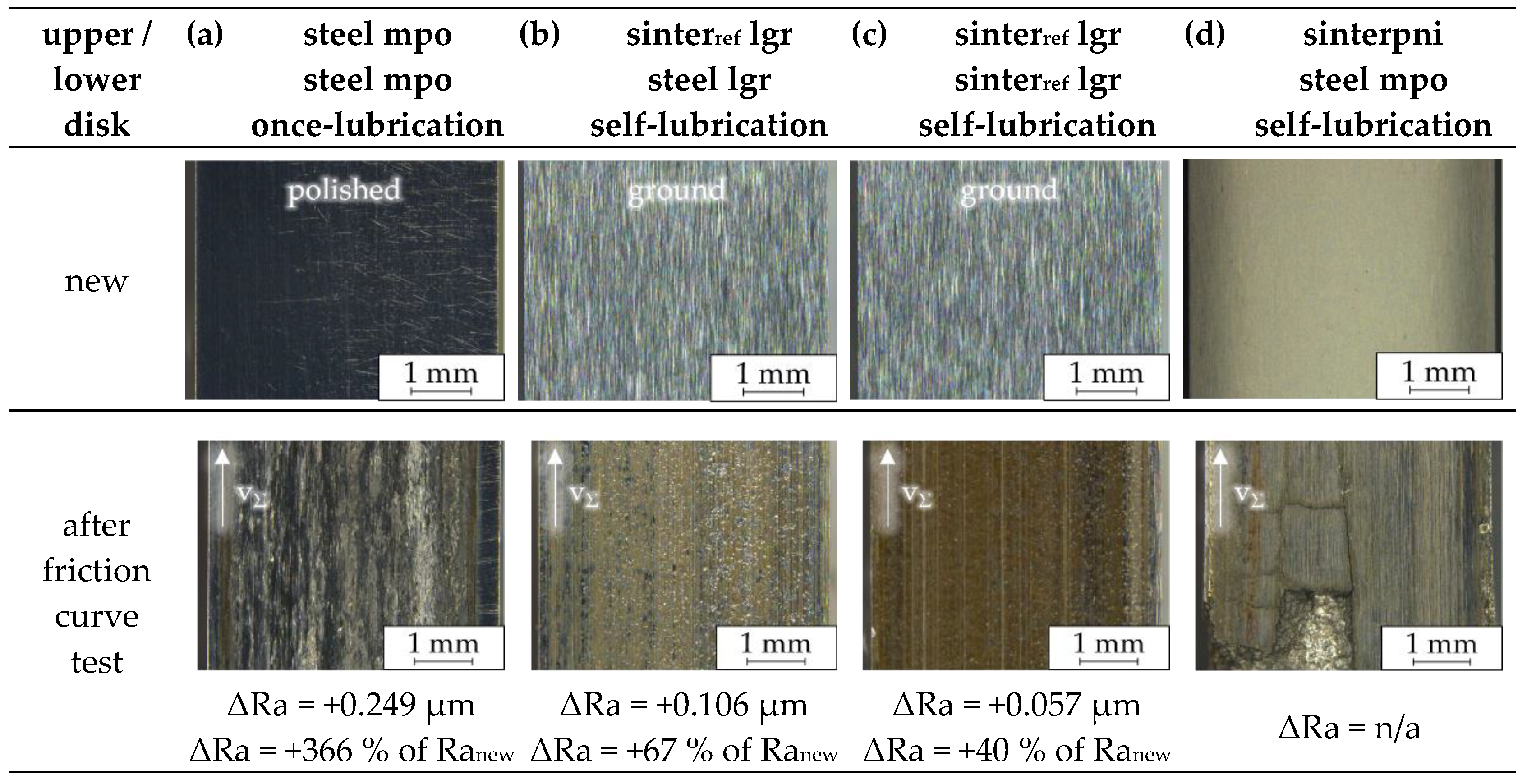
Tests were conducted on different material pairings, i.e., steel–steel, steel–sinter, and sinter–sinter material disk pairs. To evaluate the operating behavior of the EHL tribosystem according to the considered material combination, the measured friction and bulk temperature curves of the friction curve tests (see Section 3.1) and the long-term tests (see Section 3.2) as well as surface measurements are analyzed. For this, Figure 18a–d shows the surface alteration of the upper disk of the 1st disk pair after the 2nd friction curve test run compared to the new surfaces. Additionally, the absolute and relative difference of the arithmetic mean surface roughness ΔRa before and after the test is determined.

4.1.1. EHL Tribosystem without Oil-Impregnated Sinter Disks under Once-Lubrication and with One Oil-Impregnated sinterref Disk under Self-Lubrication

The tests with once-lubricated disk pairs with two steel disks or with one steel and one sinterref disk without oil impregnation but with the initially added oil quantity Vinit could not be fully completed in both friction curve (see Figure 6a,b) and long-term tests (see Figure 15), due to continuously increasing µ and ϑM reaching the termination limits after a comparatively short number of load cycles (see Table 5 and Table 6). With the failure of the once-lubricated tribosystem without an oil-impregnated partner, the functionality of self-lubrication due to extruding oil of the pores supplementing the initial lubricant quantity Vinit could be verified as expected and could be separated from a possible presumption that the measured frictional behavior with at least one oil-impregnated specimen is achieved just by the PAO100 oil with its PD additives. Further, the surfaces of the EHL tribosystems under self-lubrication via oil-impregnated sinter disks show less severe surface alteration compared to the once-lubricated EHL tribosystems (see Figure 18a,b), which show heavy alteration characterized by abrasively and/or adhesively altered regions of the initially very smooth polished steel disk surface after the comparatively short test runs. The heavy alteration is also verified by a significant relative increase of surface roughness of ΔRa = 366% compared to the moderate increase of surface roughness of ΔRa = 67% of the self-lubricating disk pair with one longitudinally ground, oil-impregnated sinterref disk. With this, an improvement of the heavy mixed lubrication regime by thermal expansion-, elastic deformation-, and centrifugal force-driven extruding oil out of the material structure into the tribocontact (see [25]) can be assumed, which can increase the lubricant film thickness to a sufficient film thickness (see [27]) to further separate the mating surfaces, which consequently results in less surface alteration.
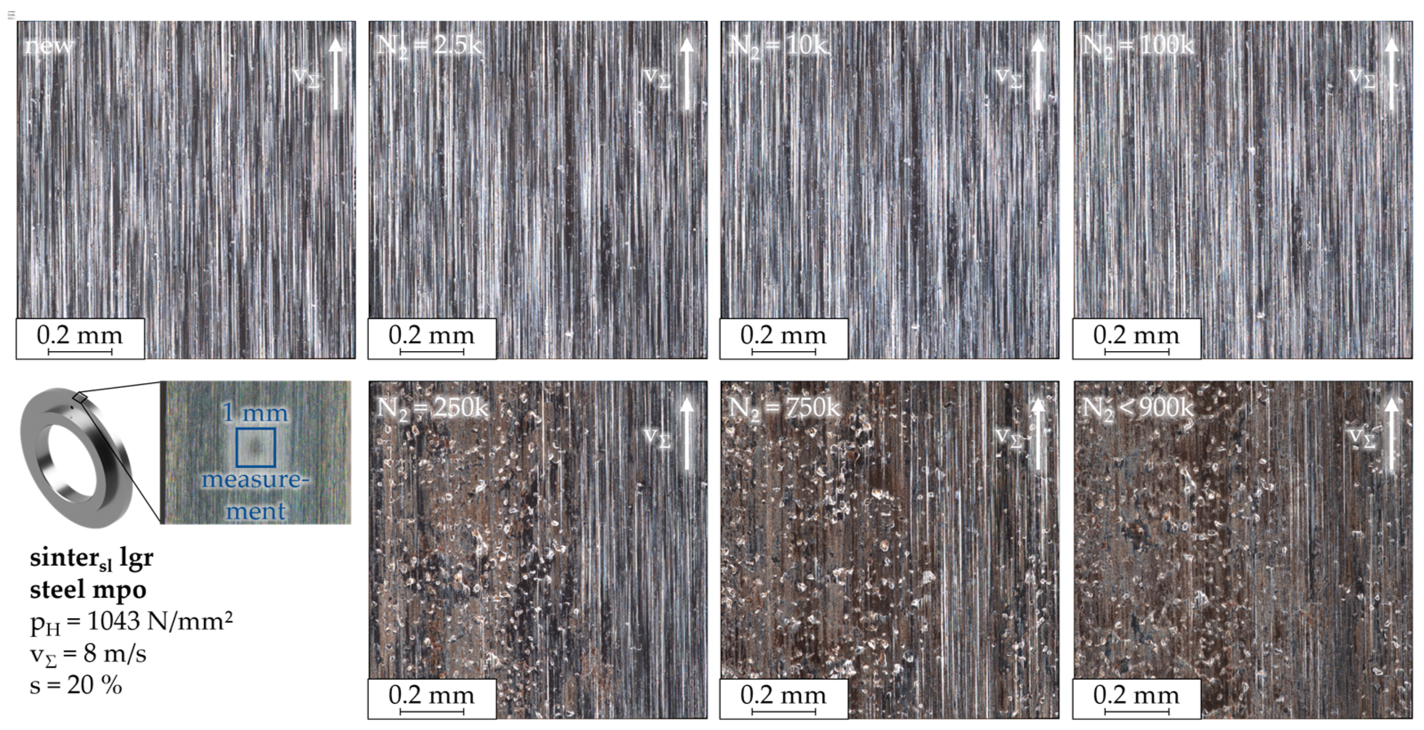
To further evaluate the operating behavior due to surface alteration analysis during the long-term tests, surface measurements were taken at intermittent intervals (see Section 2.3). Figure 19 shows the surface images sequentially taken during the long-term test with the 1st disk pair with the longitudinally ground steel and sinterref disk pair under self-lubrication. Initially, nearly no pores are optically visible in the 2D images of the 1 mm2 square area in the center of the disk surface. However, immediately after the first load cycles, there is an optically recognizable increasing change in the surface appearance, with increasing visible pores in terms of number and size. By the end of the test, the surface appearance is characterized by regions smoothed due to wear but also longitudinally oriented marks scattered with numerous pores as qualitatively determined. Areas around the pores appear less stressed, indicating local oil extrusion and possible locally improved lubrication regimes, which was also seen in the lubricant film investigation with an optical ball-on-disk tribometer by Ebner [47]. To verify the subjective identification of pores based on the 2D representation of the surface images using simultaneously measured 3D data, the depth information from the 3D topography measurement of the surface can be used. Round shaped areas deeper than the reference level in the form of holes in the material surface represent potential oil extruding pores connected to the inner oil-storing pore structure. Figure 20 shows the topography measurements of the sinterref disk of the 1st disk pair with a longitudinally ground steel and a longitudinally ground sinterref disk before the test, after N2 = 2.5 k, and at the end of the test (here: N2 > 1.2 M). The sequential measurements show that initially, even with the grinding marks, pores can be detected through round holes that are deeper than the marks. Thus, initially there are a few randomly distributed pores on the unworn surface. After the first load cycles, the number of identifiable pores increases slightly. In addition, an influenced area of oil transported to the surface can be seen around the pores, where the initial grinding structure is still visible, indicating locally relatively low solid contact ratios and ongoing abrasion. By the end of the test, the number of pores has increased slightly again, with the diameter of the pores appearing larger. The surface seems to be smoothed due to alteration, but the initially uniform grinding direction remains over the whole test.

4.1.2. EHL Tribosystem with One Oil-Impregnated sinterpni Disk under Self-Lubrication

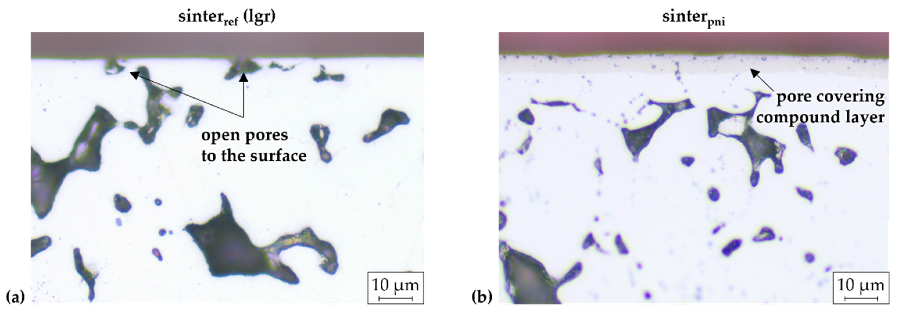
The friction curve tests with sinterpni were automatically and abruptly terminated by the test rig acceleration detector after a few load cycles (see Section 3.1.3). Further, Figure 18d shows the surface images of the sinterpni disk before and after the friction curve test. Before the test, the images of the sinterpni disk surfaces of the new disks indicate a low to no presence of surface pores that enable the oil to flow across the surface, thus enabling the self-lubrication principle, leading to predicted failure of the test. The failure presumably resulted from the surface pores covered by the compound layer. Figure 21a,b shows the sectional images of a new longitudinally ground sinterref and a sinterpni disk and verifies the presumption of the covered near-surface pores by the compound layer, which prevents oil flow to the surface, resulting in insufficient support for the lubricant film and reduced friction-reducing effects as with, e.g., sinterref disk pairs. As a consequence, the compound layer delaminated during the friction curve tests (see image of sinterpni disk after friction curve test in Figure 18d), which led to heavy surface damage, causing significant vibration.

4.1.3. EHL Tribosystem with Two Oil-Impregnated sinterref Disks under Self-Lubrication

The test with self-lubricating disk pairs of two longitudinally ground, oil-impregnated sinterref material resulted in no improvement of tribological performance due to mainly higher levels of µmax and ϑM,max in all tests with both disk pairs as well as higher differences of Δµmax and ΔϑM,max between the 1st and the 2nd tests with the 1st disk pair compared to the reference EHL tribosystem with just one oil-impregnated sinterref disk paired with a steel disk (see Figure 7a,b and Figure 8a,b, Table 5 and Table 6). Surface alteration of both disk pair variants, the sinterref–sinterref disk pair (see Figure 18c) and the reference steel–sinterref disk pair (see Figure 18b), can be seen in a subjectively determined local increase of pore numbers, pore size, and regions with tribofilms, as well as an objectively measured relative increase of ΔRa = 40% and ΔRa = 67%, respectively. A disk pair comprising two oil-impregnated sinter disks exhibits less benefits in tribological behavior, i.e., primarily repeatable low levels of µ and ϑM, than a disk pair with one steel disk and one sinter disk. Consequently, the latter disk pair is considered the most effective. This can be due to a one-sided flow of the oil extruding from the surface for EHL lubricant film formation as well as intrusion back from the tribocontact under high hydrodynamic pressure into the porous material. Presumably because of the back-intrusion in permeable bodies, a smaller lubricant film thickness-reducing effect dominates the tribocontact compared to the tribocontact within an EHL tribosystem with two porous structures and thus a two-sided oil intrusion with a higher total permeability of the tribocontact, which led in Ebner’s [25] calculations of self-lubricating EHL tribosystem configurations with increasing permeability to a decreasing lubricant film thickness.

4.1.4. EHL Tribosystem with One Non-Impregnated sintersl Disk under Once-Lubrication or One Oil-Impregnated sintersl Disk under Self-Lubrication

Sintersl material with MoS2 and WS2 solid lubricant additives showed in once-lubricated long-term tests at the reference operating conditions compared to the unstable running once-lubricated steel–steel tribosystem a longer lifetime up to N2 = 0.35 M at moderate operating conditions with at least half of the lifetime running with stable operating behavior before failing, with decent increasing friction and bulk temperatures (see Figure 15). With this, the expected solid friction reducing influence of the solid lubricant in the sinter material is proven. When impregnating the sintersl material additionally with oil, the effect of solid friction reduction via a solid lubricant as well as liquid lubrication via extruded oil out of the pores are combined, which repeatably leads to the lowest levels of µ and ϑM measured, with the lowest difference between the tests with two identical disk pair specifications, and continuously stable, quasi-stationary operating behavior (see Table 6).

4.2. Influence of the Surface on the Operating Behavior

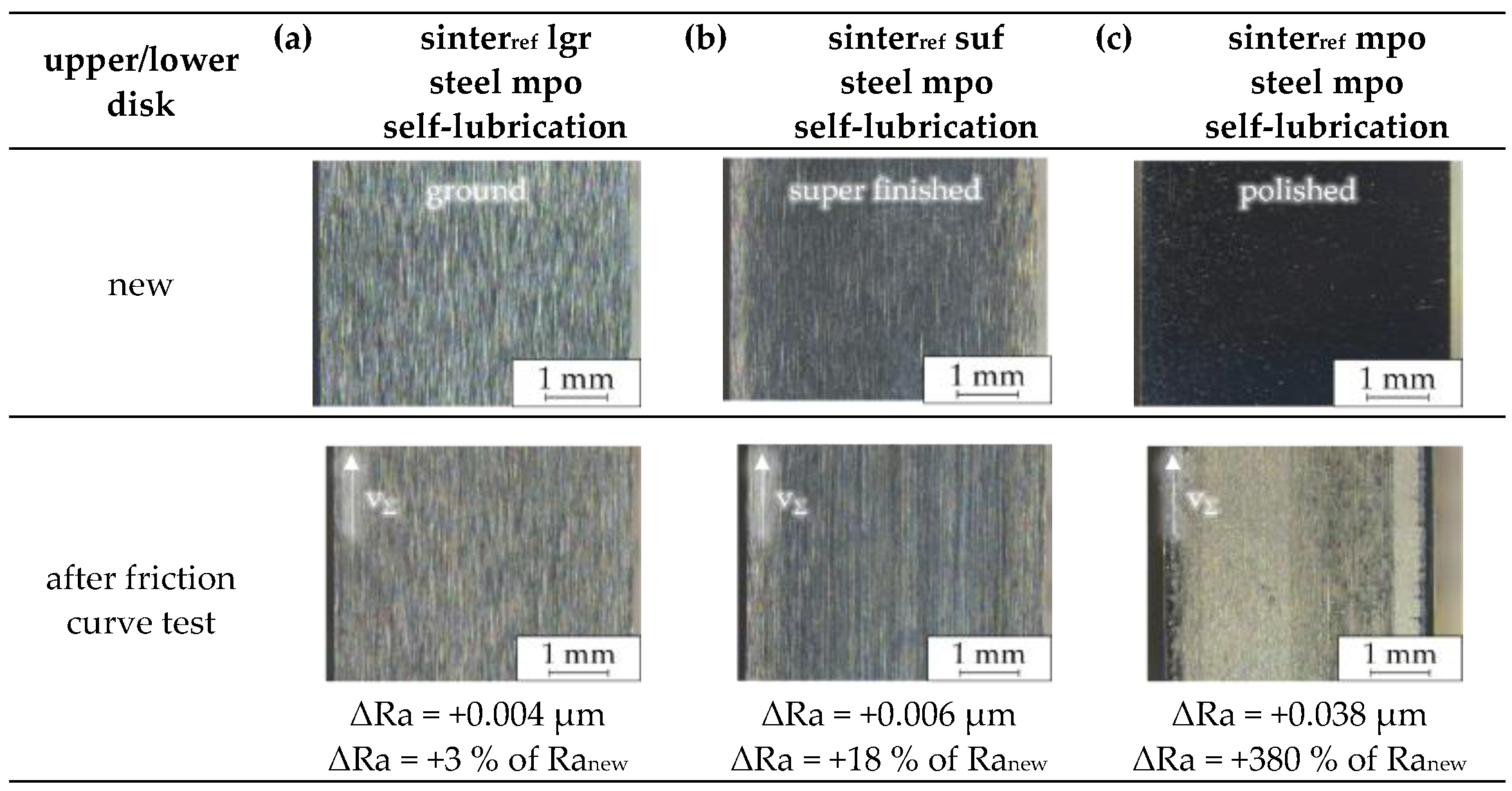
Test were also conducted on different surface finish pairings, i.e., longitudinally and axially ground, superfinished, and mechanically polished. To evaluate the influence of surface finishes on the frictional behavior, stability of the operating behavior, and lifetime behavior of self-lubricating rolling-sliding contacts with oil-impregnated sintered material, again the measured friction and bulk temperature curves of the friction curve tests (see Section 3.1) and the long-term tests (see Section 3.2) as well as surface measurements are analyzed. For conventionally lubricated EHL tribosystems, the direct link between surface roughness and frictional behavior is commonly known. For self-lubricating EHL tribosystems with oil-impregnated sintered materials, the study suggests that smoother surfaces may result in lower friction, but surface finishing can affect the possible deviations of surface porosity and thus the prevailing oil flow within the tribocontact. This, in turn, affects the global and local lubrication and friction regime. For this, Figure 22a–c shows the surface alteration of the upper disk of the 1st disk pair after the 2nd friction curve test run compared to the new surfaces, and the absolute and relative difference of the arithmetic mean surface roughness ΔRa before and after the test is determined.

4.2.1. EHL Tribosystem with Ground Steel Disk and Sinter Disk Surfaces under Self-Lubrication

Tests with ground EHL tribosystem partners were conducted with longitudinally and axially ground disk surfaces.
The tests with the reference tribosystem with longitudinally ground steel and sinterref disks show in the friction curve tests a typical tribological behavior of injection-lubricated rolling-sliding contacts, with a transition from a linear increase of the coefficient of friction at a low slip ratio to a thermal regime with decreasing coefficient of friction at a higher slip ratio, as well as lower values of µ and higher ϑM with increasing v (see Figure 3a,b and Figure 4a,b). All operating points can be tested in both test runs with the 1st disk pair as well as with 2nd disk pair. In long-term tests under reference conditions, the reference tribosystem (see Figure 14) shows slightly higher µ and ϑM compared to injection-lubricated disk pairs (see Figure 13), which can be caused by less cooling via convection by the surrounding external oil as well as lower oil amounts for sufficient lubricant film formation. However, the reference tribosystem reaches the aimed end of the test at N2 > 1.2 M without termination. The tests of the self-lubricating EHL tribosystem with an axially ground steel and sintersl disk with both surfaces similar to gear tooth flank surfaces could be completed without termination (see Figure 17) as well as with a proper tribological performance with decreasing levels of friction with test progress and a mostly stable to metastable operating behavior. The EHL tribosystem with a steel disk and a sinterref disk shows severe tribological performance with a metastable to unstable operating behavior, leading to friction and bulk temperature increase with test progress and, thus, termination at N2 < 0.88 M and < 0.25 M.

4.2.2. EHL Tribosystem with a Smoothed Steel Disk Surface Paired with a Longitudinally Ground Sinter Disk Surface under Self-Lubrication

The variation in the steel disk surface, from ground to polished finish, expectedly results in a significant improvement in the tribological behavior of a self-lubricating contact with a ground oil-impregnated sinter material. This improvement can be seen in the better repeatability of the 1st friction curve tests of the two disk pairs, as well as the lower difference between the 1st and 2nd test with the 1st disk pair and the overall slightly lower levels of µ and ϑM compared to the reference tribosystem (see Figure 9a,b and Figure 10a,b and Table 5). Compared to the operating behavior of the injection-lubricated EHL tribosystem in the long-term tests (see Figure 13), the levels of µ and ϑM with the self-lubricating disk pair with a polished steel disk and a longitudinally ground sinterref disk are lower for part of the test duration up to the whole test duration. This might be mainly caused by the improved lubrication regime, due to lower arithmetic mean surface roughness of the contact partners. Because there is no heat convection by an external oil, the friction-induced temperature of the tribosystem increases during operation, which decreases the oil viscosity and thereby increases the influence of the surface roughness of both mating partners on the lubricant film thickness. This consequently leads to an increase of solid friction and thus an increase of total friction measured. This can also be seen in the documentation in Figure 22a of the surface alteration, in which the surface of the ground sinterref disk shows nearly no alteration in terms of tribofilm formation, pore number, or size increase as well as ΔRa (ΔRa = 3%).

4.2.3. EHL Tribosystem with a Smoothed Steel Disk Surface Paired with a Smoothed sinterref Disk Surface under Self-Lubrication

The friction curve test results with an additional polished steel smoothed surface of the sinter disk also show the trend of an improved tribological behavior of a reduction in surface roughness by superfinishing or polishing, resulting in lower measured levels of µ and ϑM compared to tests with conventionally ground surfaces (see Figure 9a,b, Figure 10a,b, Figure 11a,b and Figure 12a,b and Table 5). In the following sections, the influence of the finish variants of mechanically polishing and superfinishing of the sinterref disk surface on the operating behavior is evaluated in detail.

Superfinishing of the sinterref Disk Surface

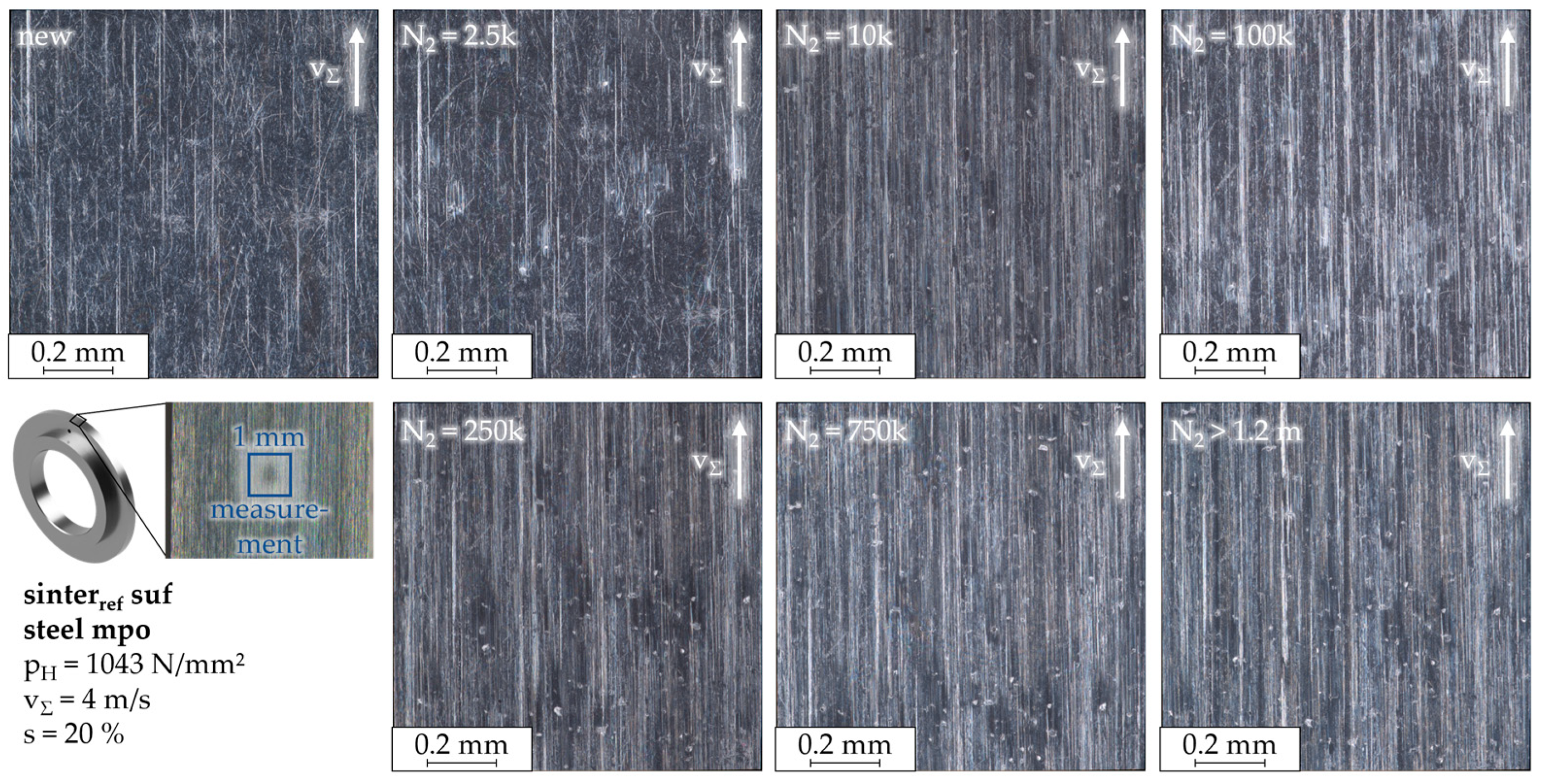
In addition to the results that the tests with disk pairs with a superfinished sinterref disk surface show better repeatability of the 1st tests of two disk pairs and lower difference of the measured µ and ϑM between the test of the 1st and the 2nd disk pair compared to the reference system as well as the lowest levels of µ and the most stable operating behavior during the long-term tests compared to the other surface variants in Figure 14a,b (see also Table 6), Figure 22b shows the low surface roughness increases with ΔRa = 18%, with an absolute increase of ΔRa = 0.006 µm, which is negligible. Further, Figure 23 shows the 2D image documentation of the surface alteration during the long-term tests at reference conditions with the mechanically polished steel and superfinished sinterref disk pair. Similar to the tribosystem with two longitudinally ground disks, at the initial state, only a few surface pores are visibly recognizable. Additionally, there is a less uniform direction of the surface structure obtained. After a few load cycles, the surface pores are numerous and increase in size, whereas the initial surface structure shows for a longer time less global alteration. Furthermore, the surface area surrounding the pores shows significant deviations locally in the pore-free surface regions. The initial state of the altered porosity and surface modification after the first load cycles persists, with a similar appearance throughout the whole test. Figure 24 shows, additionally, the topography measurements of the sinterref disk of the 1st disk pair with a mechanically polished steel disk and a longitudinally ground sinterref disk before the test, after N2 = 2.5 k, and at the end of the test. The measurements confirm the observation, as evidenced by the identifiable pores, verified by depth information, which initially increase slightly and then remain constant over time. The less severe alteration of the disk surfaces can be interpreted as another result of the comparably best tribological behavior evaluated within the surface variants, which again verifies Ebner’s findings [25].
With the surface images and topography measurements of the best-performing disk pair surface combinations, it can be stated that in tests that show good tribological behavior and do not lead to premature termination due to metastable or unstable operating behavior, the porosity becomes more uncovered initially and, thus, is more exposed, which can be interpreted as a running-in process of oil-impregnated sinter materials with surface finish. Subsequently, once there is sufficient oil exchange between the inner material structure and the tribocontact through the opened surface pores, there are no significant changes in surface porosity.

Mechanical Polishing of the sinterref Disk Surface

In contrast, the friction curve test with the comparably smoothest sinterref disk, a mechanically polished surface, shows greater difference between the 1st and 2nd tests with the 1st disk pair and a worse repeatability of the tests with two disk pairs compared to an EHL tribosystem with a mechanically polished steel disk and a longitudinally ground or superfinished sinterref disk. It is postulated that the manual polishing process results in inconsistencies in abrasive material removal and pore closure. While this facilitates the requisite smoothing of the surfaces and thus a comparatively high increase of the minimum lubricant film thickness, it also gives rise to unexpected and divergent measurement results due to local surface porosity emphasis. Further, the additional effort of mechanically smoothing the sinter disk surface is less useful when evaluating the surface alteration shown in Figure 22c, which shows a significant optical change of the surface with a measured increase of ΔRa = 380%. With this, the surface finish of mechanically polishing the sinter disks was excluded for the subsequently run long-term tests.

4.3. Influence of the Operating Conditions on the Operating Behavior

Tests with disk pairs of a mechanically polished steel disk and a longitudinally ground sinterref disk were also conducted with a comparably higher load or sum velocity. To evaluate the operating behavior of the EHL tribosystem according to the prevailing operating condition, the measured friction and bulk temperature curves of the friction curve tests (see Section 3.1) and the long-term tests (see Section 3.2) as well as surface measurements are analyzed.

4.3.1. EHL Tribosystem under Comparably Higher Load

The increase in transmitted power during the long-term tests at higher loads initially exhibits areas with metastable operating behavior, which transitions into stable operating behavior after further load cycles in both tests of the two disk pairs (see Figure 16). Initially, there is a measurable difference of µ between the tests of the two disk pairs, which gradually converges to nearly identical stable operating behavior at the same level. Thus, the influence of load increase in long-term tests results in a slightly higher level of both μ and ϑM compared to the tests at the reference load (see Table 6), but a functional tribosystem is still maintained throughout the entire intended test. The increased measured friction is primarily attributed to the higher specific friction in the tribocontact at higher pressure.

4.3.2. EHL Tribosystem under Comparably Higher Sum Velocity

In contrast to the increased load, the impact of an increased speed of vΣ = 8 m/s exerts a more pronounced influence on the operating behavior of the self-lubricating EHL tribosystem. During the tests shown in Figure 16, the severe operating condition results in varying lifetimes, and in both tests with the two disk pairs, the test runs fail due to the emergence of unstable operating behavior at disparate times. The primary cause of this phenomenon is not only the higher specific friction power but also the increased dissipated energy generated over time, which results in increased system heating and a concomitant decrease of oil viscosity. This decrease of viscosity also reduces the lubricant film thickness, potentially increasing solid contacts. Further, Figure 25 and Figure 26 show, through 2D images and 3D topography measurements, the surface alteration of the sintersl disk of the 1st long-term tests at the increased sum velocity of vΣ = 8 m/s with the disk pairs of a polished steel and a longitudinally ground sintersl disk pair that terminated before the designated test time. Visually, there is only a slight alteration in the appearance of the ground surface within the first load cycles up to about N2 ≈ 100k. However, at N2 = 250k, corresponding to an abrupt decrease in µ, the porosity increases significantly in both number and size. At all subsequent time intervals when the surface condition was recorded, the increasing porosity correlates with the increasing measured friction until the tribosystem fails, resulting in highly pronounced surface damage characterized by numerous visible and measurable large surface pores as well as, presumably, severe wear.
With the surface images and topography measurements of the disk pairs that terminated during the long-term tests, it can be stated that in tribosystems that experience more severe tribological stress, due to factors such as the initial limited presence of surface pores or operating conditions that exceed the performance limit of the self-lubricating EHL tribosystem, porosity increases significantly. This, in turn, enables more oil to intrude from the tribocontact back into the inner material structure, reducing the lubricant film thickness. As a result, solid contacts increase, leading to increased friction and wear as well as temperature increase, which reduces oil viscosity, further promoting the formation of thinner lubricant film thickness and enhancing oil intrusion. Under these conditions, the EHL tribosystem will continue to degrade, leading also to thermal and chemical alteration of the oil with further load cycles, until the EHL tribosystem reaches its limits and fails.
The consistently good measurements of the tribological behavior of the self-lubricating EHL tribosystem at moderate to high reference operating conditions, together with the stable or metastable operating behavior at higher pressures and/or speeds, suggests the suitability of self-lubricated tribosystems for use in various operating modes, including, e.g., intermittent high-load operation followed by less loaded or unloaded cool-down periods.

5. Conclusions

This study investigated the functionality and influence of specific material and surface specifications on the operating behavior of oil-impregnated, self-lubricating sintered rolling-sliding contacts under moderate to high operating conditions. A twin-disk tribometer was used to evaluate the tribological behavior of various material disk pairs and surface finishes. Friction curve tests were performed to measure the coefficient of friction and bulk temperature, while long-term tests were performed to evaluate the lifetime behavior of promising material disk pairs and surface finishes, including friction and bulk temperature measurements. The main findings are as follows:
  • A once-lubricated EHL tribosystem without external oil lubrication performs better when a solid lubricant is added to the sintering powder prior to sintering.
  • A self-lubricating EHL tribosystem with longitudinally ground surfaces and one oil-impregnated sinter disk exhibits adequate friction behavior and, thus, mostly stable operating behavior during the tests. Two oil-impregnated sinter disks show worse tribological performance.
  • Smoothing the surface of the steel disk in the self-lubricating EHL tribosystem improves tribological performance, while finishing both contact partner surfaces by mechanical polishing of the steel disk and superfinishing of the sinter disk provides the best repeatable tribological performance.
  • For axially ground surfaces similar to typical gear tooth flanks, the best tribological performance of a self-lubricating EHL tribosystem can be achieved with a solid lubricant addition to the sintered material prior to sintering.
  • The surface alteration during the tests with EHL tribosystems with good tribological performance is characterized by a consistent running-in-like increase in pore size and quantity within the initial load cycles and an only slight additional change during the further lifetime.
  • Nevertheless, great differences in operating behavior and surface alteration are observed for disk pairs manufactured with identical requirements for mechanical properties and surface conditions.
Systematic studies of material and surface porosity, the resulting permeability, and the influence of manufacturing methods such as heat treatment, surface finishing, etc., on the surface porosity as well as on the sinter material density in near-surface regions are further needed to understand these differences in operating behavior and surface alteration.
The tests of this study were conducted under stationary operating conditions. The results demonstrated that, for a sufficient number of load cycles, self-lubricating EHL tribosystems can operate within specific load ranges, with a highly stable operating behavior and low levels of µ and ϑM. A stationary operating application with medium-high loads, such as geared motors for logistic conveyor belts, could be a viable option. Further investigations at adapted model contact tests are required to ascertain the suitability of the self-lubrication technology for promising applications under intermittent operating conditions with peaks of higher load or speeds and operating sequences under low load to cool down, e.g., in machine tools such as hand screwdrivers. In addition, the so-far limited characterization of surface porosity reveals the need for a quantitative method to determine pore size distribution and quantity, allowing for a more objective characterization of surface porosity, as the surface is considered one of the main components of future mathematical models for the design or prediction calculations of self-lubricating EHL tribosystems with oil-impregnated sintered materials.

Author Contributions

Conceptualization, N.S., T.L.; methodology, N.S., T.L.; experiments, N.S.; validation, N.S.; formal analysis, T.L.; writing—original draft preparation, N.S.; writing—review and editing, T.L., K.S.; supervision, T.L., K.S.; project administration, T.L., K.S.; funding acquisition, K.S. All authors have read and agreed to the published version of the manuscript.

Funding

The presented results are based on the research project 03LB3001A, supported by the Federal Ministry for Economic Affairs and Climate Action (BMWK) and supervised by the Project Management Jülich (PtJ). The authors are grateful for the sponsorship and support received from BMWi and Project Management Agency PtJ.

Data Availability Statement

The raw data supporting the conclusions of this article will be made available by the authors on request.

Acknowledgments

The authors would like to express their thanks to the project partners Miba Sinter Group AG for their support with the sinter material, OSK Kiefer GmbH for surface finishing support, as well as Getriebebau NORD GmbH and Hilti AG for their continued support during the project.

Conflicts of Interest

The authors declare no conflicts of interest.

References

  1. Ebner, M.; Lohner, T.; Michaelis, K.; Höhn, B.-R.; Stahl, K. Self-Lubricating Gears with Oil-Impregnated Sintered Materials. Forsch. Im Ingenieurwesen 2017, 2, 13–28. [Google Scholar]
  2. Niemann, G.; Winter, H. Maschinenelemente 2: Getriebe Allgemein, Zahnradgetriebe—Grundlagen, Stirnradgetriebe, 2nd ed.; revised; Springer: Berlin/Heidelberg, Germany, 2003; ISBN 978-3-662-11874-0. [Google Scholar]
  3. DIN 51509-1; Selection of Lubricants for Gears; Gear Lubricating Oils. Beuth GmbH: Berlin, Germany, 1976.
  4. Bartel, D. Simulation von Tribosystemen: Grundlagen und Anwendungen; Postdoctoral Thesis; 1st ed.; Vieweg + Teubner; University of Magdeburg: Wiesbaden, Germany, 2010; ISBN 978-3-8348-1241-4. [Google Scholar]
  5. Conrades, V. Proteins of the Matrix in Tissue Engineered Meniscus. Ph.D. Thesis, Technical University of Munich, München, Germany, 2007; pp. 12–20. [Google Scholar]
  6. Schatt, W. Pulvermetallurgie: Technologien und Werkstoffe, 2nd ed.; revised and extended; Springer: Berlin/Heidelberg, Germany, 2007; ISBN 3-540-23652-X. [Google Scholar]
  7. DIN 1850-3; Plain Bearings: Part 3: Sintermetal Bushes. Beuth GmbH: Berlin, Germany, 1998.
  8. Roberts, M. A Study of Oil Circulation in the R4 Spin-Axis Bearing with Sintered Nylon Ball Retainer: Proc. Gyro. Spin-Axis Hydrodynamic; Massachusetts Institute of Technology: Cambridge, UK, 1966. [Google Scholar]
  9. Fote, A.A.; Slade, B.A.; Feuerstein, S. The behavior of thin oil films in the presence of porous lubricant reservoirs. Wear 1978, 46, 377–385. [Google Scholar] [CrossRef]
  10. Bertrand, P.A.; Carré, D.J. Oil Exchange between Ball Bearings and Porous Polyimide Ball Bearing Retainers. Tribol. Trans. 1997, 40, 294–302. [Google Scholar] [CrossRef]
  11. Marchetti, M.; Meurisse, M.-H.; Vergne, P.; Sicre, J.; Durand, M. Lubricant Supply by Porous Reservoirs in Space Mechanisms. In Proceedings of the 26th Leeds-Lyon Symposium on Tribology, Leeds, UK, 14-17 September 1999; Volume 38, pp. 777–785. [Google Scholar] [CrossRef]
  12. Marchetti, M.; Meurisse, M.-H.; Vergne, P.; Sicre, J.; Durand, M. Analysis of oil supply phenomena by sintered porous reservoirs. Tribol. Lett. 2001, 10, 163–170. [Google Scholar] [CrossRef]
  13. Bertrand, P.A.; Carré, D.J.; Bauer, R. Oil Exchange Between Ball Bearings and Cotton-Phenolic Bail-Bearing Retainers. Tribol. Trans. 1995, 38, 342–352. [Google Scholar] [CrossRef]
  14. Scheichl, B.; Neacsu, I.A.; Kluwick, A. A novel view on lubricant flow undergoing cavitation in sintered journal bearings. Tribol. Int. 2015, 88, 189–209. [Google Scholar] [CrossRef]
  15. Morgan, V.T.; Cameron, A. Mechanism of lubrication in porous metal bearings. In Proceedings of the Conference on Lubrication and Wear, London, UK, 1–3 October 1957; Volume 89, pp. 151–157. [Google Scholar]
  16. Dizdar, S. Pitting Resistance of Sintered Small-Module Gears: Proceedings of the institution of Mechanical Engineers. Part J J. Eng. Tribol. 2013, 227, 1225–1240. [Google Scholar] [CrossRef]
  17. Lipp, K. Rolling Contact Fatigue of Sintered Steels under Constant and Variable Hertzian Pressure and Sliding; LBF: Darmstadt, Germany, 1997. [Google Scholar]
  18. Dlapka, M.; Danninger, H.; Gierl, C.; Lindqvist, B. Defining the pores in PM components. Met. Powder Rep. 2010, 65, 30–33. [Google Scholar] [CrossRef]
  19. Li, X.; Olofsson, U. A study on friction and wear reduction due to porosity in powder metallurgic gear materials. Tribol. Int. 2017, 110, 86–95. [Google Scholar] [CrossRef]
  20. Balasoiu, A.M.; Braun, M.J.; Moldovan, S.I. A parametric study of a porous self-circulating hydrodynamic bearing. Tribol. Int. 2013, 61, 176–193. [Google Scholar] [CrossRef]
  21. Manoylov, A.V.; Borodich, F.M.; Evans, H.P. Modelling of Elastic Properties of Sintered Materials. Proc. R. Soc. A 2013, 469. [Google Scholar] [CrossRef]
  22. Zapf, G. Handbook of Manufacturing Technology Vol. 1: Handbuch der Fertigungstechnik; Carl Hanser, München Wien: München, Germany, 1981. [Google Scholar]
  23. Ebner, M.; Lohner, T.; Michaelis, K.; Stemplinger, J.-P.; Höhn, B.-R.; Stahl, K. Self-Lubricated Elastohydrodynamic (EHL) Contacts with Oil-Impregnated Sintered Materials. In TAE 2016; Technische Akademie Esslingen: Ostfildern, Germany, 2016. [Google Scholar]
  24. Ebner, M.; Lohner, T.; Weigl, A.; Michaelis, K.; Stemplinger, J.-P.; Höhn, B.-R.; Stahl, K. Hochbelastete und schmierstoffgetränkte Wälzpaarungen aus Sintermaterial ohne externe Schmierstoffzuführung. Tribol. Schmier. 2016, 63, 22–30. [Google Scholar]
  25. Ebner, M. Self-Lubrication of Highly-Loaded Gear Contacts with Oil-Impregnated Porous Ferrous Metals. Ph.D. Thesis, Technical University of Munich, Munich, Germany, 2021. [Google Scholar]
  26. Ebner, M.; Lohner, T.; Stahl, K. Konstruktionselemente mit Hertz’scher Punkt- oder Linienlast und Schlupf in der Kontaktfläche ohne äußere Schmierung: DFG Koselleck Final Report; German Research Foundation: München, Germany, 2019. [Google Scholar]
  27. Ebner, M.; Schwarz, A. Einfluss Poröser Oberflächen auf die Selbstschmierung: 2. Tribologie-Kolloquium des GfT-Arbeitskreises München; Gesellschaft für Tribologie e.V.: Jülich, Germany, 2019. [Google Scholar]
  28. Omasta, M.; Ebner, M.; Sperka, P.; Lohner, T.; Krupka, I.; Hartl, M.; Höhn, B.-R.; Stahl, K. Film formation in EHL contacts with oil-impregnated sintered materials. Ind. Lubr. Tribol. 2018, 70, 612–619. [Google Scholar] [CrossRef]
  29. Ebner, M.; Schwarz, A. Selbstschmierende hochbelastete Wälzpaarungen: 2. Tribologie-Kolloquium des GfT-Arbeitskreises München; Gesellschaft für Tribologie e.V.: Jülich, Germany, 2019. [Google Scholar]
  30. Zhang, S.; Li, Y.; Hu, L.; Feng, D.; Wang, H. AntiWear Effect of Mo and W Nanoparticles as Additives for Multialkylated Cyclopentanes Oil in Vacuum. J. Tribol. 2017, 139, 021607. [Google Scholar] [CrossRef]
  31. Rabaso, P.; Ville, F.; Dassenoy, F.; Diaby, M.; Afanasiev, P.; Cavoret, J.; Vacher, B.; Le Mogne, T. Boundary lubrication: Influence of the size and structure of inorganic fullerene-like MoS2 nanoparticles on friction and wear reduction. Wear 2014, 320, 161–178. [Google Scholar] [CrossRef]
  32. Srinivas, V.; Rao, C.K.R.; Abyudaya, M.; Jyothi, E.S. Extreme Pressure Properties of 600 N Base Oil Dispersed with Molybdenum Disulphide Nano Particles. Univers. J. Mech. Eng. 2014, 2, 220–225. [Google Scholar] [CrossRef]
  33. Bakunin, V.N.; Suslov, A.Y.; Kuzmina, G.N.; Parenago, O.P.; Topchiev, A.V. Synthesis and Application of Inorganic Nanoparticles as Lubricant Components ÔÇô a Review. J. Nanoparticle Res. 2004, 6, 273–284. [Google Scholar] [CrossRef]
  34. Zhu, S.; Cheng, J.; Qiao, Z.; Yang, J. High temperature solid-lubricating materials: A review. Tribol. Int. 2019, 133, 206–223. [Google Scholar] [CrossRef]
  35. Vazirisereshk, M.R.; Martini, A.; Strubbe, D.A.; Baykara, M.Z. Solid Lubrication with MoS2: A Review. Lubricants 2019, 7, 57. [Google Scholar] [CrossRef]
  36. Kovalchenko, A.M.; Fushchich, O.I.; Danyluk, S. The tribological properties and mechanism of wear of Cu-based sintered powder materials containing molybdenum disulfide and molybdenum diselenite under unlubricated sliding against copper. Wear 2012, 290, 106–123. [Google Scholar] [CrossRef]
  37. Dhanasekaran, S.; Gnanamoorthy, R. Dry sliding friction and wear characteristics of Fe–C–Cu alloy containing molybdenum di sulphide. Mater. Des. 2007, 28, 1135–1141. [Google Scholar] [CrossRef]
  38. DIN 30910-6; Sintered Metal Materials: Sint-Material Specifications: Hot-Forged Sintered Steels for Structural Parts. Beuth GmbH: Berlin, Germany, 1990.
  39. DIN EN ISO 5755; Sintered Metal Material: Specifications. Beuth GmbH: Berlin, Germany, 2022.
  40. DIN EN ISO 13565-1; Geometrical Product Specifications (GPS)—Surface Texture: Profile Method—Surfaces Having Stratified Functional Properties: Part 1: Filtering and General Measurement Conditions. Beuth GmbH: Berlin, Germany, 1998.
  41. Cai, J.; Jin, T.; Kou, J.; Zou, S.; Xiao, J.; Meng, Q. Lucas-Washburn Equation-Based Modeling of Capillary-Driven Flow in Porous Systems. Langmuir 2021, 37, 1623–1636. [Google Scholar] [CrossRef] [PubMed]
  42. Hamraoui, A.; Nylander, T. Analytical approach for the Lucas-Washburn equation. J. Colloid Interface Sci. 2002, 250, 415–421. [Google Scholar] [CrossRef] [PubMed]
  43. Lados, D.; Apelian, D.; Semel, F.J. Open and Closed Porosity in P/M Materials: Measurement and Variation with Density Levels and Sintering Conditions; Euro PM 2005 Tools for Improving PM; European Powder Metallurgy Association: Prague, Czech Republic, 2005. [Google Scholar]
  44. Lohner, T.; Merz, R.; Mayer, J.; Michaelis, K.; Kopnarski, M.; Stahl, K. On the Effect of Plastic Deformation (PD) Additives in Lubricants. Tribol. Und Schmier. 2015, 62, 13–24. [Google Scholar]
  45. UK Castrol Ltd. Castrol Optigear Synthetic PD…ES: Product Data Sheet; BP Europa SE: Hamburg, Germany, 2019. [Google Scholar]
  46. Vojacek, H. Das Reibungsverhalten von Fluiden unter Elastohydrodynamischen Bedingungen. Einfluss der Chemischen Struktur des Fluides, der Werkstoffe und der Makro- und Mikrogeometrie der Gleit/Wälzkörper. Ph.D. Thesis, Technical University of Munich, Munich, Germany, 1984. [Google Scholar]
  47. Ebner, M.; Omasta, M.; Lohner, T.; Sperka, P.; Krupka, I.; Hartl, M.; Michaelis, K.; Höhn, B.-R.; Stahl, K. Local Effects in EHL Contacts with Oil-Impregnated Sintered Materials. Lubricants 2019, 7, 1. [Google Scholar] [CrossRef]
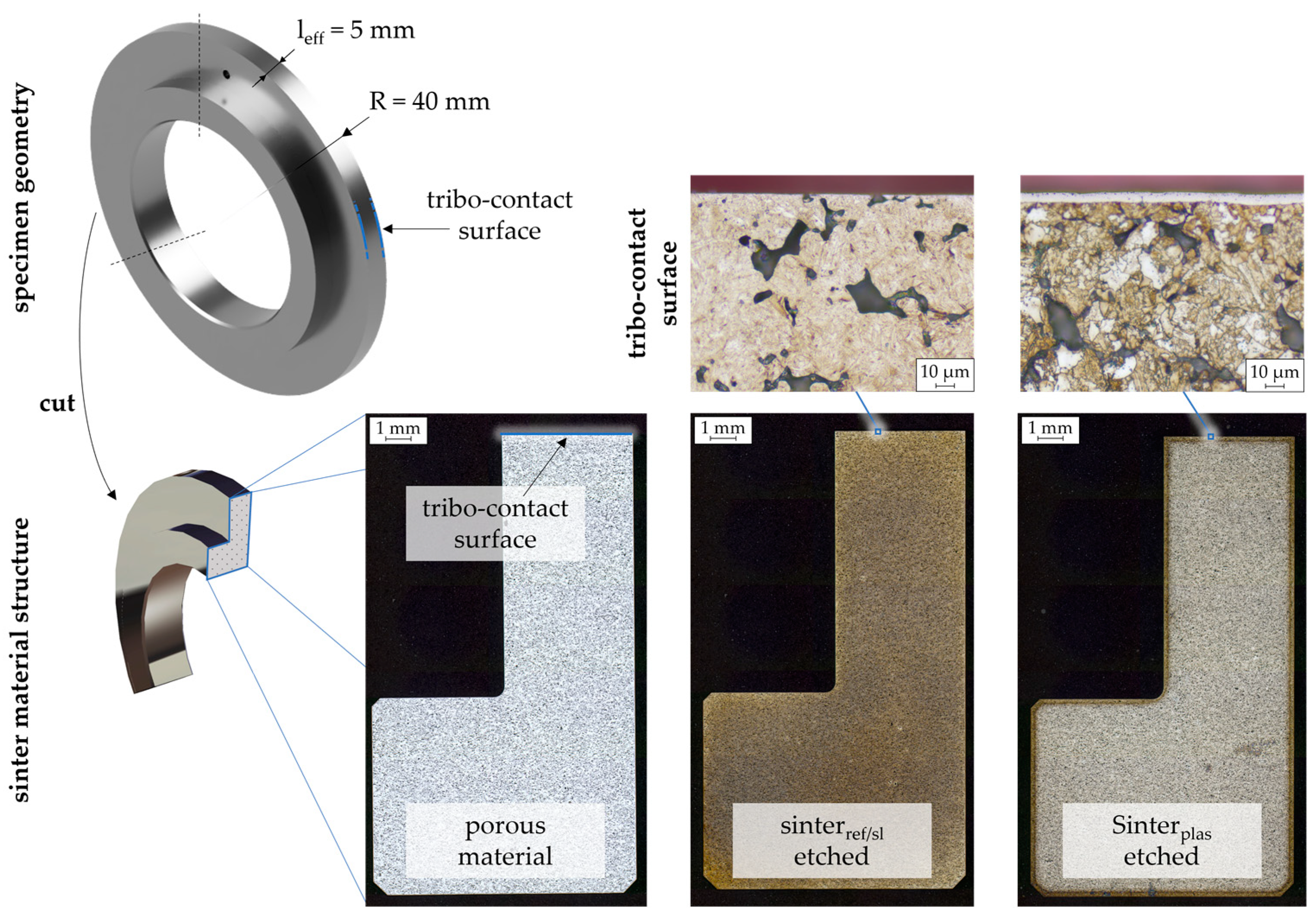
Figure 1. Specimen geometry and section images of the porous sinter material variants.
Lubricants 12 00259 g001
Figure 2. FZG twin-disk tribometer according to Ebner [23] and disk pairs used for the tests of this study.
Lubricants 12 00259 g002
Figure 3. Friction curves (a) and bulk temperature curves (b) and each of their maximum level (c,d) of the 1st test of two disk pairs of a longitudinally ground sinterref disk and a longitudinally ground steel disk under self-lubrication.
Lubricants 12 00259 g003
Figure 4. Friction curves (a) and bulk temperature curves (b) and each of their maximum level as well as maximum difference (c,d) of two tests of the 1st disk pair of a longitudinally ground sinterref disk and a longitudinally ground steel disk under self-lubrication.
Lubricants 12 00259 g004
Figure 5. Friction curves (a) and bulk temperature curves (b) and each of their maximum level as well as maximum difference (c,d) of two tests of the 1st disk pair of two longitudinally ground steel disks under injection lubrication.
Lubricants 12 00259 g005
Figure 6. Friction curves (a) and bulk temperature curves (b) and each of their maximum level (c,d) of the 1st test of two disk pairs of two mechanically polished steel disks under once-lubrication.
Lubricants 12 00259 g006
Figure 7. Friction curves (a) and bulk temperature curves (b) and each of their maximum level (c,d) of the 1st test of two disk pairs of two longitudinally ground sinterref disks under self-lubrication.
Lubricants 12 00259 g007
Figure 8. Friction curves (a) and bulk temperature curves (b) and each of their maximum level as well as maximum difference (c,d) of two tests of the 1st disk pair with two longitudinally ground sinterref disks under self-lubrication.
Lubricants 12 00259 g008
Figure 9. Friction curve maximum µmax (a) and bulk temperature maximum ϑM,max (b) of the friction curve tests with sinter material and surface variants under self-lubrication.
Lubricants 12 00259 g009
Figure 10. Maximum difference of the friction curves Δµmax (a) and the bulk temperature curves ΔϑM,max (b) of the friction curve tests with sinter material and surface variants under self-lubrication.
Lubricants 12 00259 g010
Figure 11. Friction curves (a) and bulk temperature curves (b) and each of their maximum level (c,d) of the 1st test of two disk pairs of a polished steel disk and a superfinished sinterref disk under self-lubrication.
Lubricants 12 00259 g011
Figure 12. Friction curves (a) and bulk temperature curves (b) and each of their maximum level as well as maximum difference (c,d) of two tests of the 1st disk pair with a polished steel disk and a superfinished sinterref disk under self-lubrication.
Lubricants 12 00259 g012
Figure 13. Friction curves of the long-term tests of two longitudinally ground steel disk pairs under injection lubrication and two disk pairs with a polished steel disk and a longitudinally ground sinterref disk under self-lubrication.
Lubricants 12 00259 g013
Figure 14. Friction curves (a) and bulk temperature curves (b) of the long-term tests with disk pairs of a longitudinally ground or mechanically polished steel disk and a longitudinally ground or superfinished sinterref disk under self-lubrication.
Lubricants 12 00259 g014
Figure 15. Friction curves of the long-term tests with disk pairs of a mechanically polished steel disk and a longitudinally ground sinterref or sintersl disk under once-lubrication and self-lubrication.
Lubricants 12 00259 g015
Figure 16. Friction curves of the long-term tests at different v or pH levels with disk pairs of a mechanically polished steel disk and a longitudinally ground sintersl disk under self-lubrication.
Lubricants 12 00259 g016
Figure 17. Friction curves of the long-term tests with axially ground disk pairs of a steel disk and a sinterref or sintersl disk under self-lubrication.
Lubricants 12 00259 g017
Figure 18. Surface images and absolute and relative difference of arithmetic mean roughness ΔRa of the upper disk surface of the 1st disk pair before the friction curve tests and after the 2nd test run.
Lubricants 12 00259 g018
Figure 19. 2D surface images of the upper disk surface of the 1st disk pair with a longitudinally ground steel and sinterref disk sequentially made during the long-term tests under self-lubrication.
Lubricants 12 00259 g019
Figure 20. 3D surface measurement of the upper disk surface of the 1st disk pair with a longitudinally ground steel and sinterref disk sequentially made during the long-term tests under self-lubrication.
Lubricants 12 00259 g020
Figure 21. Sectional image of the near-surface porous structure of a longitudinally ground sinterref disk (a) and a sinterpni disk without surface finish (b).
Lubricants 12 00259 g021
Figure 22. Surface images and absolute and relative difference of arithmetic mean roughness ΔRa of the upper disk surface of the 1st disk pair before the friction curve tests and after the 2nd test run.
Lubricants 12 00259 g022
Figure 23. 2D surface images of the upper disk surface of the 1st disk pair with a mechanically polished steel and a superfinished sinterref disk sequentially made during the long-term tests under self-lubrication.
Lubricants 12 00259 g023
Figure 24. 3D surface measurement of the upper disk surface of the 1st disk pair with a mechanically polished steel and a superfinished sinterref disk sequentially made during the long-term tests under self-lubrication.
Lubricants 12 00259 g024
Figure 25. 2D surface images of the upper disk surface of the 1st disk pair with a mechanically polished steel and a longitudinally ground sinterref disk sequentially made during the long-term tests at higher vΣ under self-lubrication.
Lubricants 12 00259 g025
Figure 26. 3D surface measurement of the upper disk surface of the 1st disk pair with a mechanically polished steel and a longitudinally ground sinterref disk sequentially made during the long-term tests at higher vΣ under self-lubrication.
Lubricants 12 00259 g026
Table 1. Mechanical properties of the considered materials.
MaterialYoung’s Modulus E in GPaPoisson’s
Ratio ν
Surface
Hardness
Density
ρ in g/cm3
steel2100.30745 HV57.8
sinterref/sl1300.27755 HV57.0
sinterpni1400.27785 HV57.0
Table 2. Surfaces of the considered specimen.
Longitudinally
Ground (lgr)
Axially
Ground (agr)
Superfinished
(suf)
Mechanically
Polished (mpo)
Plasma
Nitride (pni)
Lubricants 12 00259 i001Lubricants 12 00259 i002Lubricants 12 00259 i003Lubricants 12 00259 i004Lubricants 12 00259 i005
Table 3. Data of the considered oil PAO100+PD [45].
ISO VGDensity ρoil at 15 °C
in kg/m3
Kin. Viscosity η40°C
at 40 °C in mm2/s
Kin. Viscosity η100°C
at 100 °C in mm2/s
100849105.015.7
Table 4. Intermittent measurement intervals during long-term operation tests.
Measurement Intervals
Load cycle number N2>2.5 k>10 k>30 k<100 k>250 k>750 k>1200 k
Time t in h0.080.331382448
Table 5. Maximum friction µmax, maximum bulk temperature ϑM,max, and total load cycles N2 of the upper disk of all friction curve tests with both the 1st and the 2nd disk pair as well as maximum difference of the friction Δµmax and maximum difference of the bulk temperature ΔϑM,max between the 1st and the 2nd test of the 1st disk pair.
Lubrication Method
Upper/Lower Disk
pH = 600 N/mm2
s = 0…50%
µmax at vΣϑM,max in °C at vΣN2 in M
2 m/s4 m/s8 m/s2 m/s4 m/s8 m/sTotal
once-lubrication
steel mpo/steel mpo
1.1 4>0.120 1x 2x 2>140 1x 2x 2x 2
1.2 5x 2x 2x 2xx 2x 2x 2
Δµmaxx 2x 2x 2xx 2x 2
2.1 6>0.120 1x 2x 2>140 1x 2x 2x 2
injection lubrication
steel lgr/steel lgr
1.1 40.0570.0380.0353843520.03
1.2 50.0550.0340.0334043520.03
Δµmax0.0020.0010.002100
2.1 6- 3- 3- 3- 3- 3- 3- 3
self-lubrication
sinterref lgr/steel lgr
1.1 40.0640.0510.04756761090.15
1.2 50.0830.0510.04660671040.17
Δµmax0.0190.0080.005995
2.1 60.0570.0420.04753641090.14
self-lubrication
sinterref lgr/sinterref lgr
1.1 40.0760.0600.0525163790.13
1.2 50.1200.0630.0626690900.20
Δµmax0.0550.0230.033171715
2.160.0720.0790.04451881220.16
self-lubrication
sinterref lgr/steel mpo
1.1 40.0570.0470.0254666720.13
1.2 50.0490.0460.0274566700.13
Δµmax0.0100.0030.004102
2.1 60.0330.0250.0204666710.13
self-lubrication
sinterref suf/steel mpo
1.1 40.0420.0330.0264353690.12
1.2 50.0400.0340.0264453690.12
Δµmax0.0020.0020.002313
2.1 60.0340.0260.0224356790.13
self-lubrication
sinterref mpo/steel mpo
1.1 40.0860.0410.0314256760.14
1.2 50.0610.0410.0344658770.13
Δµmax0.0250.0070.004622
2.1 60.1200.110>0.120 110183>140 10.08 1
self-lubrication
sinterpni/steel mpo
1.1 4>0.120 1x 2x 2>140 1x 2x 2x 2
1.2 5x 2x 2x 2x 2x 2x 2x 2
Δµmaxx 2x 2x 2x 2x 2x 2
2.1 6>0.120 1x 2x 2>140 1x 2x 2x 2
1: termination at operating point; 2: no value because of termination; 3: no test conducted; 4: 1st disk pair, 1st test; 5: 1st disk pair, 2nd test; 6: 2nd disk pair, 1st test.
Table 6. Mean friction µ ¯ 1st and µ ¯ 2nd, mean bulk temperature ϑ ¯ M|1st and ϑ ¯ M|2nd, relative load cycles of the upper disk N2|1st and N2|1st, and stability coefficients Ξ1st and Ξ2nd of all long-term tests and maximum difference of friction Δµmax between the long-term tests with the 1st and 2nd disk pairs.
Lubrication Method
Upper/Lower Disk
pH = 1043 N/mm2
vΣ = 4 m/s
s = 20%
µ ¯ 1st
µ ¯ 2nd
Δµmax ϑ ¯ M|1st
ϑ ¯ M|2nd
in °C
N2|1st/N2|48h
N2|2nd/N2|48h
in %
Ξ1st
Ξ2nd
once-lubrication
sinterref lgr/steel mpo
0.094
0.052
0.05992
52
<1
<1
0.07
0.07
once-lubrication
sintersl lgr/steel mpo
0.051
0.047
0.05793
86
≈29
≈40
0.46
0.48
injection lubrication
steel lgr/steel lgr
0.047
0.047
0.00556
56
100
100
0.76
0.95
self-lubrication
sinterref lgr/steel lgr
0.051
0.043
0.01385
78
100
100
0.45
0.38
self-lubrication
sinterref lgr/steel mpo
0.045
0.035
0.02082
70
100
100
0.51
0.71
self-lubrication
sinterref suf/steel mpo
0.031
0.036
0.00862
70
100
100
1.00
0.69
self-lubrication
sintersl lgr/steel mpo
0.032
0.033
0.00265
68
100
100
1.00
1.00
self-lubrication
sinterref agr/steel agr
0.073
0.057
0.041110
92
≈73
≈21
0.30
0.15
self-lubrication
sintersl agr/steel agr
0.053
0.047
0.01091
87
100
100
0.27
0.56
self-lubrication 1
sintersl lgr/steel mpo
0.045
0.039
0.01186
87
100
100
0.46
0.43
self-lubrication 2
sintersl lgr/steel mpo
0.042
0.042
0.016117
116
≈90
≈37
0.48
0.18
1: operating condition variation at pH = 1200 N/mm2; 2: operating condition variation at vΣ = 8 m/s.
Disclaimer/Publisher’s Note: The statements, opinions and data contained in all publications are solely those of the individual author(s) and contributor(s) and not of MDPI and/or the editor(s). MDPI and/or the editor(s) disclaim responsibility for any injury to people or property resulting from any ideas, methods, instructions or products referred to in the content.