Review

A Review on the Dynamic Performance Studies of Gas Foil Bearings

1
School of Mechanical Engineering and Automation, Harbin Institute of Technology, Shenzhen, Shenzhen 518055, China
2
Shenzhen Key Laboratory of Flexible Printed Electronics Technology, Shenzhen 518055, China
*
Authors to whom correspondence should be addressed.
These authors contributed equally to this work.
Lubricants 2024, 12(7), 262; https://doi.org/10.3390/lubricants12070262
Submission received: 4 June 2024 / Revised: 7 July 2024 / Accepted: 17 July 2024 / Published: 22 July 2024
(This article belongs to the Special Issue Gas Lubrication and Dry Gas Seal)

Abstract

:
Gas foil bearings have important and wide applications in high-speed turbomachinery, generating low frictional lubricating gas film in series with underlying elastic foil structures to support the rotor system. Their dynamic performance is of vital significance in maintaining the rotor stability as well as in depressing rotor vibrations. This paper conducts a comprehensive review on dynamic performance studies conducted on gas foil bearings, including research on the dynamic stiffness and damping coefficients, bearing stability, nonlinear vibrations of the rotor–bearing system, and active methods for controlling rotor dynamic motions. This review provides clear observations towards the developments and iterations of the models, methods, and experiments of these studies.

1. Introduction

A gas foil bearing (GFB) is a self-acting passive bearing lubricated by thin aerodynamic gas film, which is characterized by elastic foil structures [1,2]. The foil structures usually consist of one or multiple smooth top foils to generate the converged gas film through the hydrodynamic effect. Besides the top foil, there are also underlying elastic foil structures that play major roles in load carrying. Aerodynamic force is transmitted to the bearing sleeve or housing through the foil structures. It results in corresponding foil deformations, which in turn can change the gas film clearance distributions as well as aerodynamic characteristics and help increase the adaptabilities of rotor misalignment, manufacturing errors, and thermal expansion in extremely high-temperature applications [3]. Meanwhile, there are also relative sticking–sliding behaviors on the mating faces of foil structures due to Coulomb frictions, resulting in a hysteresis effect of force–displacement curves, i.e., a Coulomb damping effect. It is worth noting that this paper will focus on the dynamics studies of journaled GFBs; of course, thrust GFBs [4,5] also have impacts on the dynamic performance of the rotor–bearing system in maintaining stability in the axial direction and suppressing vibration. However, to the best of the authors’ knowledge, the journal bearings have more significance for affecting the system dynamic characteristics.
GFBs were first invented in 1960s for application in the air cycle machines (ACMs) of airplanes and tanks [6]. And it has broader applications areas, such as high-speed blowers in sewerage, gas turbines in auxiliary power units (APUs), high-speed compressors in fuel cells, turboexpanders [7], turbochargers for engines, etc., with the increasing demand for high-power density turbomachinery [8,9]. Different types of gas foil bearings are proposed and studied according to the configurations of foil structures. The most famous GFBs are the leaf-type [10], bump-type [11], and beam-type [12] foil bearings, as shown in Figure 1. The leaf-type bearing invented by Garrett AiResearch has multiple curve foils, where one foil leaf is overlapped on the next along the rotor rotating direction [13]. Multiple converged gas film clearances and foil assembly preload are formed due to the overlapping configuration. The bump-type foil bearing, invented by Mechanical Technology Inc., possesses corrugated underlying elastic foil structures that help increase the load capacity. The beam-type bearing invented by Capstone Turbine is characterized by the beam foil, which has multiple elastic beam structures manufactured through chemical etching. Except for these three famous types, as shown in Figure 2, there are also other different types of gas foil bearings such as the metal mesh type [14], wing foil type [15], spring type [16,17], hybrid types [18,19], protuberant type [20], novel type with a negative Poisson’s ratio structure [21], etc. The dynamic characteristics of different types of GFBs are summarized in Table 1.
From the aspects of GFB development, the refinements of foil structures are usually classified into three generations [22]. First-generation foil bearings have uniform foil structures in the axial and circumferential directions [23]. Second-generation foil bearings have a tailored foil structure or foil stiffness in either the axial or circumferential direction [24]. Third-generation foil bearings have variable foil structures or foil stiffness in both directions, sometimes in the foil deformation direction [25,26]. The performance predictions of higher-generation foil bearings are challenging due to the more complex foil structures, which require the development of elaborate mechanical models.
According to the literature review about the modeling improvements of gas foil bearings [27,28,29,30,31,32,33,34,35], it is inferred that the models focusing on bearing static performance investigations have achieved significant progress. In these studies, ref. [27,28,29] focus on the foil structural modeling and [30,31,32,33,34,35] also include the fluid–structure modeling to study the aero-elastic bearing load capacity. Additionally, considering the effect of fluid–structure coupling, Iordanoff proposed an inverse method for rapidly designing the compliant foil thrust bearing based on the deformed foil profile and foil compliance [36]. Grau and Iordanoff et al. then applied this thought and method to a journal foil bearing to determine the original definition of the bearing profile based on the aero-elastic coupling effects [37]. Kim and Andres studied a heavily loaded gas foil bearing in which the journal eccentricities exceed the nominal bearing clearance by three times under the fluid–structure coupling effect [38]. In contrast to the parametrical studies and inverse method for designing gas foil bearing under fluid–structure coupling effects, Kumar and Khamari et al. first conducted sensitivity analyses and provided the optimum ranges of design parameters of gas foil thrust bearings [39]. Then, the authors further applied artificial intelligence techniques (ANN and ANFIS methodologies) to conduct the optimization.
From the aero-elastic coupling effect, it is found that the aerodynamic gas film is in series with foil structures supporting the high-speed rotor. The gas film and foil structures both possess individual inherent stiffness and damping characteristics, contributing to the stabilization of the rotor from different aspects. Compared with lower rotor speeds, the viscous damping of gas film is less effective at high rotor speeds. In this condition, the Coulomb damping from micro-sliding behaviors of foil structures help supplement the overall bearing damping to stabilize the rotor. The deformations and Coulomb damping of foil structures also assist in suppressing the random vibrations as well as resisting instantaneous shocking vibrations.
In recent years, based on the foundations of static performance analyses, the studies about the dynamic performance of gas foil bearings are also impressive [40]. This paper conducts a comprehensive review on these dynamics studies to provide a clear understanding of the observations and contributions. The outline of this paper is organized as follows: Section 2 reviews the studies about dynamic coefficients and the linear stability of GFBs; Section 3 reviews the studies about the nonlinear rotor stability and vibrations supported by GFBs; and Section 4 reviews the studies about the active methods of controlling GFB dynamic performance.

2. Dynamic Coefficients of GFB

2.1. Dynamic Stiffness and Damping of Foil Structures

2.1.1. Modeling Studies of Bump-Type Bearings

Ku and Heshmat first conducted modeling studies on the foil structural dynamic coefficients of bump-type foil bearings. They used the previously proposed mechanical model of a bump structure in GFBs [41] to calculate and study the bearing dynamic stiffness and damping coefficients considering the effect of Coulomb friction [42]. The authors calculated the motions of a disturbed rotor under its interactions with foil structures, obtaining closed hysteresis curves. The dynamic stiffnesses of foil structures were calculated by analyzing the reaction forces and disturbance amplitudes in different directions. The areas enclosed by hysteresis curves represent the energy dissipated by Coulomb friction damping. The equivalent structural viscous damping can be calculated based on the disturbance frequency and amplitude. In the following study [43], the authors further studied the effects of different parameters on the dynamic stiffness coefficients of a three-pad GFB, which increase with the increase in static eccentricity and increase with the decrease in disturbance amplitude and excitation frequency. Meanwhile, when the loading direction points towards the middle of single pad, the calculated dynamic coefficients reach their maximum values, while when the loading direction points to between two adjacent pads, the dynamic coefficient values are small. There are also optimal friction coefficients that enable the dynamic coefficients to reach asymptotic values. It is worth noting that the above studies by Ku and Heshmat were conducted with the quasi-static model and are not the real sense dynamic model.
In the following studies, researchers started to develop real-time models in the dynamics studies of foil structures. Swanson simplified a single bump into two springs in series and a frictional force related to the external load [44]. The author conducted a concise and in-depth study on the impact mechanism of Coulomb friction on the dynamic characteristics of a bump structure. The author analyzed the effects of disturbance frequency, dynamic load, and excitation amplitude on the Couloumb damping. Le Lez and Arghir et al. studied the dynamic response of a bump foil strip in the time domain based on a multi-DOF static model [45]. The authors, based on the dynamic friction model proposed by Petrov and Edwins [46], used the inverse cosine function to discretize the discontinuous Coulomb friction problem in the time domain and further studied the Coulomb friction damping of bump foil structures. The results indicate that appropriately increasing the friction coefficient can increase the dissipated energy of foil structure, but too large of a friction coefficient will hinder the sliding of the bump foil, thereby reducing the dissipated energy. Meanwhile, for the bump foil strip containing 10 bumps, only the 5 bumps near the free end are able to slide during the loading–unloading process. This indicates that taloring the entire bump foil strip into multiple segments along the circumferential direction can improve bearing damping characteristics. The above two studies mainly investigated the dynamic characteristics of one bump or bump strip with several bumps rather than a complete circular bump foil structure assembled into the bearing.
Feng et. al established a dynamic foil structural model [47] based on the link-spring bump model [30] and LuGre dynamic friction model [48]. The dynamic characteristics of a short foil strip with six bumps and the full-size foil structure were calculated. The results show that increased excitation frequency tends to increase the structural dynamic stiffness and loss factor but remarkably decreases the equvivalent dynamic damping. In addition, larger friction coefficients tend to increase all three of these dynamic coefficients, while larger exciation amplitudes tend to decrease these coefficients. Hoffmann et al. enhanced the wedging effect or bearing preload by adding a metal shim between the bump foil and bearing sleeve [49]. The dynamic model development of bump foil structures also referenced the link-spring bump model proposed by Feng [30]. The authors applied dynamic excitation forces to the bearing and measured the dynamic responses for obtaining the dynamic stiffness and damping coefficients of the foil structure. The results indicate that adding a metal shim enlarges the phase range of bump sliding, thus increasing the dynamic damping. If the dynamic excitation force points to the direction between metal shims, the structural dynamic coefficients can be greatly improved.
Zywica et. al established the dynamic excitation model of a bump foil bearing with a rotor inserted using Abaqus CAE software [50]. Hysteresis curves at different amplitudes of dynamic load and different assembly preloads, i.e., radial clearances, were obtained in the simulations. The results indicate that a larger amplitude of dynamic load evidently increased the dynamic stiffness and damping coefficients both at 40 and 80 Hz. Similarly, reducing the bearing clearance can also improve bearing dynamic performance by increasing dynamic cofficients.
The studies in this section can be categorized as follows. Studies [42,43] applied the quasi-static model, and [44,45,46,47,48,49,50] developed the real-time dynamic model. Studies [44,45] investigated the dynamic characteristics of one bump or bump strip with several bumps rather than a complete circular bump foil, and [47,49,50] focus on the full bearing structure. Ref. [49] studied a foil bearing with metal shims providing a mechanical preload, and other studies focused on a circular bearing without a mechanical preload. Ref. [50] adopted commercial software to complete complex simulations, and other studies applied self-developed models and codes. Table 2 summarized the key contributions of the modeling studies on the foil structural dynamic coefficients of bump-type foil bearings.

2.1.2. Experimental Studies of Bump-Type Bearings

As for experimental studies, Ku and Heshmat applied dynamic forces to the bump foil bearing in both horizontal and vertical directions through two perpendicular exciters, as shown in Figure 3 [51,52]. A cross-shaped yoke was installed on each end of the journal to function as a rigid force transmission path, ensuring that the yoke’s dynamics would not disrupt the measurement of the bump foil strip’s dynamic properties. The bearing static load was supported by a set of springs, with their displacement being controlled by an air cylinder. The non-rotating journal bearing was stimulated by two electromagnetic shakers, one shaking vertically and the other horizontally. Force transducers were fixed to the outer surface of the yoke at the central transverse location, with a flexible stinger linking one end of the force transducer to the shaker at the other end. The authors measured the dynamic forces in different directions and the corresponding dynamic displacements of the bearing sleeve and calculated the dynamic stiffness and damping coefficients. The experimental results show that the main stiffness and damping coefficient decrease with the increase in dynamic disturbance amplitude, while their influence on the cross stiffness and damping coefficient is relatively small. Meanwhile, higher excitation frequency leads to an increase in main stiffness coefficients and decreases in main damping coefficients; a higher static load can improve both main dynamic stiffness and damping coefficients.
Then, the authors conducted loading and unloading experiments on a flat bump foil strip containing a number of individual bumps and calculated the dynamic stiffness and damping coefficient of the foil structure based on the obtained hysteresis curves [53]. In Figure 4, the lower pad serves as a housing, while the upper pad is supported by a bump foil strip. When the lower pad moves or vibrates vertically, the bumps deform in both the vertical and horizontal directions. A horizontal hard dowel acts as a pivot between a circular plate and the upper pad, which can be placed in any of five grooves. A vertical dowel inserted tightly into the circular plate and loosely into the upper pad prevents horizontal motion of the upper pad. Bump deflection is measured by the extensometer and the load capacity is obtained through the force transducer. The authors also studied the effects of bump parameters, contact surface coating, static load, dynamic displacement amplitude, and pivot position (different load distributions) on the dynamic stiffness and damping coefficients of the foil structure. The results show that the bump pitch has significant influences on the dynamic stiffness coefficients, and both the dynamic stiffness and damping coefficients are mainly affected by the sum of friction coefficients of each contact surface. Choosing a surface coating with a higher friction coefficient will increase the Coulomb damping coefficients, and increasing the static load will increase the main stiffness and damping coefficients.
Salehi and Heshmat et al. processed the data obtained from excitation experiments using the hysteresis curve method and the single degree of freedom model, respectively, and they evaluated the dynamic stiffness and damping characteristics of foil structures [54]. The authors believe that the Coulomb friction coefficient is also a function of static load, disturbance amplitude, and excitation frequency, and they obtained a semi-empirical formula for the dynamic damping and friction coefficient.
Rubio and San Andres studied the dynamic characteristics of foil structures by conducting excitation experiments on static rotors supported by bump foil bearings [55]. As shown in Figure 5, the setup included two aluminum pedestals supporting a non-rotating steel shaft. A slender stinger connected the test foil bearing to an electromagnetic shaker. A piezoelectric load cell measured the dynamic force from the shaker, connecting the stinger end and the bearing housing. An eddy current sensor recorded the bearing’s dynamic displacement. The research found that the friction coefficient increases with the increase in dynamic load (4–20 N) (0.05–0.2). The frictional loss factor is less affected by the variation of excitation frequency but increases with the increase in dynamic load amplitude (0.05–0.23). Meanwhile, when the dynamic load is small, the stick/slide effect of the Coulomb friction is evident, and so is the hardening effect of the foil stiffness. The dynamic stiffness coefficients decrease with the increase in dynamic load.
Kim and Breedlove conducted experiments to investigate the influences of temperature on the dynamic characteristics of bump foil structure [56]. They found that as the shaft temperature increases to 188 °C, the bearing dynamic foil stiffness decreases by 50% due to housing thermal expansions at an excitation frequency of 40 Hz and dynamic damping decreases by 45%. Meanwhile, the frictional coefficient decreases by 17% with the increase in shaft temperature. Larsen et. al investigated the mechanical behaviors of bump foil strip theoretically and experimentally [57]. Its test rig in Figure 6 consists of two steel blocks, with the upper block using linear ball bearings for vertical movement, minimizing tilting. The foil strip is placed between the blocks, allowing for a direct correlation between the upper block’s displacement and the foil’s deflections. Displacements are measured with three probes, and dynamic loading is performed using an electromagnetic shaker. Quasi-static and dynamic hysteresis curves were obtained in the tests, which demonstrated that hysteresis curves under dynamic loads of high frequency seem to be more flattened and possess a smaller enclosed area. The authors attributed this phenomenon to the reduction of the sticking phase caused by the reduction in friction coefficients during high-frequency excitations of contact faces rather than by the influence of inertia force.
Table 3 summarized the key contributions of experimental studies on foil structural dynamic coefficients of bump-type bearings.

2.1.3. Studies of Other Types of Foil Bearings

The above studies are all based on the bump-type foil bearings, and there are also relavant studies about foil structural dynamic behaviors focusing on other types of foil bearings, such as the leaf-type and beam-type bearings. Schmiedeke et. al experimentally studied the dynamic performance of the leaf-type foil bearing with an underspring through dynamic excitation tests [58]. They found that the tested foil structural loss factor is obviously larger when the rotor rotating speed is below the liftoff speed compared with when the rotor is over the liftoff speed. This indicates that the frictions caused by the rotor–foil contact before rotor liftoff increase the measured damping and loss factor. Li et. al established a nonlinear finite element model of the overlapped foil structure of a leaf-type foil bearing which, for the first time, calculated hysteresis curves influenced by Coloumb friction [59]. The model is also able to conduct a numerical simulation of the overlapping assembly of multiple foil leaves and the simulation of rotor insertion to a small inscribed circle generated by overlapped foil leaves. Feng et. al conducted an experimental study on the static and dynamic foil structural characteristics of the beam-type foil bearing [60]. Static push–pull tests obtained the nonlinear foil stiffness, showing an obvious hardening effect. Dynamic excitation test results show that the foil structural stiffness first decrease with the increase in exciation frequecy from about 20 to 60 Hz and then show a continuously increasing trend when the excitation frequency further increases to 200 Hz. In comparison, the dynamic damping always decrease with the increase in excitation frequency. It is interesting that the dynamic stiffness and damping are lower when the motion amplitude is larger, which is different from the results of bump foil bearings, as discussed before.

2.2. Dynamic Coefficients of the Aero-Elastic System and Linear Stability

When the aerodynamic effect caused by the rotating rotor is included, the foil bearing performance is different from that of the static rotor condition as the gas film is in series with the foil structure supporting the rotor, and the dynamic coefficients are no longer determined by only one physical field.
Lund was the first researcher to use dynamic stiffness and damping coefficients obtained through the perturbation method to calculate the critical speed and analyze the unbalanced response as well as stability of the gas bearing–rotor system [61]. As for gas foil bearings, Peng and Carpinoare were the first researchers to consider the flexibility of the bump foil structure and calculate the bearing dynamic stiffness and damping coefficients using the small pertubation method [62]. The dynamic coefficients under different bump foil flexibilities and bearing numbers were analyzed. The results concluded that when the rotational speed is low, gas film stiffness is relatively small compared with that of the foil structure. Therefore, the aeroelastic bearing stiffness values with different flexibility coefficients show little difference, all approaching the stiffness value of gas film. If the rotational speed is higher, the gas film stiffness gradually increases to larger values compared with that of the foil structure, whose flexibility begins to affect the aeroelastic stiffness under this condition. However, this study did not consider the influence of Coulomb damping.
Afterwards, the authors introduced viscous damping to equivalent Coulomb friction damping and applied the finite difference method to solve the perturbed Reynolds equation [63]. The results indicate that the dynamic damping of foil bearing is smaller than that of rigid bearing when Coulomb damping is neglected which, however, will surpass the rigid bearing if Coulomb damping is considered. In addition, at low speeds and light loads, gas film damping plays a major role in maintaining rotor stability, while at high speeds and heavy loads, foil Coulomb damping begins to function.
The authors’ following study incorporated real foil configuration in the indirect small perturbation method, considering the membrane effect of curve foil structures, which tends to increase the principle stiffness but reduces the damping values, especially under the condition of large bearing numbers [64]. In addition, the study was also concluded on the phenomenon where larger friction coefficient can increase the dynamic stiffness and damping coefficients but will gradually approach asymptotic values.
Carpino and Talmage also applied the finite element method to solve the dynamic coefficients of bump foil bearings based on the actual geometry and physical properties of foil structures [65]. The effects of frequency, orbit size, and friction coefficient were studied, and a comparison of the energy disspated by gas film and foil structure was also conducted; the authors observed that higher excitation frequency and smaller orbit size lead to less disspicated energy and smaller damping coefficients. However, the study also concluded that a larger friction coefficient also results in an insufficient damping ability of foil structures due to the similarity of rigid bearing characteristics.
Howard and Dellacorte were the first researchers to investigate the effect of high temperature on bearing dynamic coefficients [66]. They found that when temperature rises to a certain value, the friction coefficient will suddenly decrease to around 0.35 and remain unchanged, and the type of damping changes from viscous to Coulomb friction. In addition, high temperatures can cause decreases in dynamic stiffness, but the decrement is less than an order of magnitude. The increased Coulomb damping will weaken the impact of reduced stiffness on bearing stability.
Kim compared the dynamic characteristics and stabilities of three-pad and one-pad bump foil bearings, applying the linear pertubation method and trajectory method, respectively [67]. A large discrepancy of predicting the onset speed of instability based on the two methods was obtained in this study. Similarly, Larsen et al. also calculated discrepancies using these two methods and observed that the error tends to increase with the decrease in foil stiffness [68]. The reason for the predicting discrepancy was determined by the authors to be due to the Taylor expansion of pressure pertubation only considering the influence of rotor eccentricities and neglecting the item relating to foil deformation. Osmanski followed the study of Larsen and studied the linear stability of gas foil bearings based on three approaches that used classical perturbation, extended perturbation, and the Jacobian eigenvalue, repectively [69]. The extended perturbation of gas film pressure was derived considering the influence of foil deformation on gas film thickness distributions, obtaining close instability speed to the Jacobian method and eliminating the discrepancies with the transient orbit method.
Pronobis and Liebich ascribed the discrepancy to the fact that the method in [62] regarded the excitation frequency of foil structures as being the same as the rotor rotating frequency [70], which is not consistent with the situations in transient analyses with multiple vibration modes. The authors developed a revised foil structural perturbation model by taking the self-excitated eigenfrequent vibration into account, and the modified model predicted more close critical instability results compared with the transient responses.
However, Hoffmann et al. obtained close calculation results of instability speeds to those calculated by these two approaches [71], which is different from the studies of Kim [67] and Larsen [68]. In addition, the author studied the influence of static load and bearing foil structure, i.e., one circular bump, three bump pads, and a bump foil with metal shims on the bearing stability, calculating an evidently higher onset speed of instability (173% increment) for the bearing with metal shims.
Gu et al. proposed a model to calculate the dynamic coefficients based on a perturbed finite element model of complex foil structures [72], obtaining an almost consistent instability rotor speed with the transient method and having the ability to solve the relevant problems with actual configuration of the foil bearing. In their latest study [73], the multi-mode problem was solved by applying an s-domain (complete frequency domain) impedance, and the nonlinear eigenvalue problem was established based on the state-space representation.
Bonello and Pham first proposed a method using eigenvalues extracted from the Jacobian matrix to predict static equilibrium stability [74]. However, only stability plots are presented in this study, and the foil structures are modeled as a simple elastic foundation. Then, Bonello refined this eigenvalue method on the one hand by presenting Campbell maps with whirl modes and mode-specific initial conditions and on the other by incorporating complex foil structures [75]. The author then further considered the detachment of the top foil from the bump foil in the dynamic model, enabling this frequency method to be more robust [76,77].
Li and Du et al. proposed an algorithm for calculating the dynamic coefficients of a gas foil bearing with multiple sliding beams that consisted of nonlinear complex contact constraints inside foil structures [78], as shown in Figure 7. This method was achieved through deriving the dynamic equation of perturbed foil structural deformation with contact constraints, and it therefore provides solid foundations for the calculation of dynamic coefficients and the prediction of the linear stability of gas foil bearings with complex foil structures and contact constraints.
Table 4 summarizes the contributions of studies on the aeroelastic dynamic coefficients of gas bearings.

3. Nonlinear Rotor Stability and Vibrations Supported by GFBs and Bifurcation Analyses

Although the linear stability analysis of foil bearings based on the small perturbation method has the advantage of high computational efficiency, it still has limitations in calculating nonlinear rotor whirl motions, as well as disturbance problems of large rotor eccentricity featured by nonlinear gas film force characteristics.
As for the gas film bearing without underlying elastic structures, Yang and Zhu et al. studied the nonlinear stability characteristics, finding two threshold values instead of one when gas journal bearings are changed from a stable to an unstable state [79]. When the mass of the rotor is larger than the higher threshold or smaller than the lower threshold, the dynamic system is unconditionally stable and unstable, respectively. In addition, when the rotor mass is between the two threshold values, the stability is determined by the initial conditions. Wang and Chen studied the bifurcation of a rigid rotor supported by gas film bearings [80]. The system state trajectory, Poincare maps, power spectra, and bifurcation diagrams were used to analyze the complex dynamic behavior, showing transitions from T-periodic motion to 2T-, 3T-, and 4T-periodic motions when increasing the rotor mass and rotating speed. Zhang and Kang et al. investigated the bifurcation characteristics of a Jeffcott rotor system supported by gas film journal bearings [81]. Periodic, period-doubling, and quasi-periodic motions have been observed through the bifurcation analyses, indicating the strong nonlinearity of the gas film forces.
As for GFBs, San Andres et al. conducted a rotor coast-down experiment supported by bump foil bearings with an initial speed of 25,000 r/min to investigate the effects of rotor unbalance and axial pressurization on rotor dynamic responses [82]. When the rotor speed decreases from 20,000 to 15,000 r/min, the ratio of rotor subsynchronous whirl frequency to rotor rotation frequency remains at 0.5. When the rotor speed is about twice the natural frequency of the system, the subsynchronous vibration amplitude increases significantly, and it also exhibits an increasing trend with a larger rotor unbalance value. The results also conclude that axial presssurization can increase gas film damping and suppress synchronous and subsynchronous vibration. In addition, the rotor vibration characteristics are similar to that of a Duffing oscillator with multi-frequency responses [83], and the whirl frequency ratio tends to bifurcate from one-half to one-third as the rotor speed increases. Balducchi and Arghir et al. also conducted rotor coast-down tests on a rigid rotor supported by second-generation bump foil bearings [84]. The authors found that increasing both the rotational speed and rotor unbalance level can excite more components of subsynchronous vibrations. As the unbalance mass increases, vibration components with whirl frequency ratios of 0.5 and 0.25 and more complex bifurcation phenomena appear in the low-speed range. The frequency of subsynchronous vibration in the high-speed range almost does not change with the rotor speed, but nonlinear jumps will occur at different frequencies.
Guo et. al conducted series of studies on the nonlinear dynamic responses of a rigid rotor supported by bump foil bearings theoretically and experimentally [84,85,86]. The authors found that the larger bearing radial clearance leads to larger amplitudes in both synchronous and subsynchronous vibrations [85]. Furthermore, the influences of bump stiffness and energy loss factor on the subsynchronous vibrations, named frequency-locked whip motions, were investigated [86]. In addition, the authors for the first time found that the static load can lead to a high amplitude of subsynchronous motions which, however, will be suppressed under a larger static load value, and these effects are also suitable for the unbalance load [87].
Le Lez and Arghir et al. considered the node velocity and dynamic friction in a dynamic model of the foil structure [88]. The results show that there is an optimal friction coefficient value to ensure the best stability of the system, which was also obtained and analyzed in the study of Iordanoff [89]. In addition, increasing the rotor unbalance to a certain value can lead to nonlinear jumps in rotor vibration. Lee et al. established a complete weak coupling model of foil bearing–rotor system, in which the dynamic foil structural model considered the foil mass and the bump stick/slide effect [90]. The study believed that increasing the friction coefficient would increase the energy dissipation value of bumps near the free end but would decrease the energy dissipation of the bumps near the fixed end. In addition, there are optimal friction coefficient, bump foil stiffness, and circumferential bump foil strips that can minimize the amplitude of rotor synchronous vibration. Bhore et al. investigated the effects of parameters such as rotor unbalance, foil structural stiffness, and structural loss factor on the nonlinear rotor vibrations supported by bump foil bearings by plotting bifurcation diagrams [91]. The results indicated that the rotor exhibits periodic, multi-periodic, and quasi-periodic motions under different parameter values. With an increase in rotor speed, the bifurcation diagrams show that the vibration type transits between multi-periodic to quasi-periodic motion several times before transiting to divergent motion. With an increase in unbalance eccentricity, the vibration type first transits from quasi-periodic to multi-periodic motion and then back to quasi-periodic motion under a higher unbalance level. The influences of foil compliance and loss factor on nonlinear dynamics are also complex.
Hoffmann et al. found that for a rotor with a high balance level, the subsynchronous vibration is mainly affected by the nonlinearity of the gas film and is evidenced by Hopf bifurcation [92]. For a rotor with a low balance level, the rotor vibration amplitudes are larger, and the nonlinear stiffness of foil structure has significant impacts on the subsynchronous vibrations. The system vibration characteristics are similar to those of the Duffing system.
Bonello et al. established a fully coupled dynamic model of a foil bearing–rotor system [93]. Using this model, the author found that when the rotor unbalance is not considered, both experimental and theoretical results obtained a vibration component of 0.5 times the rotating frequency, indicating that this component comes from the self-excited gas film. After considering the rotor unbalance, as the speed increases, the 0.5× harmonic vibration component bifurcates into 0.33× and 0.67× components. The study concluded that gas film nonlinearity has a significant effect on the vibration characteristics and cannot be ignored. The author then compared the computational efficiencies of the finite difference method and Galerkin method with respect to solving coupled equation systems [94], and the results showed that the Galerkin method contains fewer state variables and has a higher solving efficiency. However, the foil structure model was simplified and the stiffness and damping were replaced with the equivalent linear springs and loss factor, respectively. In their following studies, Hassan and Bonello considered the interactions between individual bumps and established a dynamic model of a bump foil strip using the modal superposition method [95]. This model is effective for calculating the rotor trajectories in the time domain. The authors also compared the linear stability results of a bump foil bearing supporting a turbocharger shaft system with nonlinear calculation results in the time domain, and they obtained consistent results.
Larsen et al. conducted theoretical and experimental investigations on the dynamic response of a three-pad bump foil bearing supporting rotor system during coast-down processes [96]. The authors used the state variable method to simultaneously solve the dynamic equations of a three-coupling physical field and characterized the foil structural characteristics through equivalent stiffness and damping coefficients. The results indicated that the subsynchronous vibrations are greatly affected by the rotor speed and the unbalance level, and bifurcations appear at high rotor speeds, similar to the Duffing system. It was also found that subsynchronous vibration disappears when the rotor unbalance mass is small, indicating its difference from the traditional linear instability mechanism. Based on the bump foil model proposed by Le Lez et al. [28], Osmanski et al. [97] applied the state variable method to simultaneously solve the dynamic Reynolds equation, dynamic equation of foil structure, and rotor dynamic equation, and the authors aimed to investigate the dynamic characteristics of a three-pad bump foil bearing supporting rotor system. The study found that the theoretical model overestimates the Coulomb damping, because the simulation results are close to the experiment results when the structural loss factor is 0. Leister et al. investigated the effect of foil structure damping on the self-excited vibration of a bearing rotor system [98] based on the state variable method proposed by Bonello et al. [74]. It was found that when the foil structural stiffness is greater than a certain value, the flexible deformation of foil structure helps improve rotor stability, and as the stiffness value increases, the optimal structural damping in the critical state gradually increases.
Table 5 summarized the key contributions of nonlinear rotor dynamic studies on gas foil bearings.

4. Active Methods of Controlling GFB Dynamic Performance

Based on the aforementioned studies about the influence of initial gas film clearance, a three-pad bearing with a mechanical preload [67] and the bearing with metal shims [49] possess superior dynamic performance compared with the bearing with uniform initial film clearances. However, the mechanical preload effect of these bearings remain unchanged from startup to high-speed operation, which is vulnerable to wear damage at lower rotor speeds resulting from the smaller gas film thickness. In recent years, active methods of controlling GFB dynamic performance have been proposed to overcome the shortcomings of traditional passive GFBs with mechanical preload, in which the method of actively adjusting gas film clearance is more attractive.
Feng and Guan et. al proposed a novel foil bearing with a piezoelectric actuator to actively adjust the mechanical preload and change the gas film thickness during the bearing operations [99]. A level amplifier was designed to amplify the displacement from the actuator. The study found that higher driving voltage results in a larger mechanical preload, larger airborne drag torque, and larger difference between direct and cross-couple dynamic stiffness, i.e., better bearing stability. Rotor dynamic performance supported by an active bump-type foil bearing (ABFB) was experimentally and theoretically investigated in the following study [100], demonstrating that the larger mechanical preload caused by a higher driven voltage is able to suppress the subsynchronous vibrations and increase the onset speed of instability. In addition, the nonlinear rotor dynamics of a four-DOF ABFB–rotor system were studied by researchers based on a numerical model to explore the influences of radial clearance, flexure hinge width, and static load [101]. The results indicate that a smaller initial clearance, softer hinge, and larger static load help increase the rotor stability.
The above studies about ABFBs demonstrate the fact that the active method can indeed increase the rotor stability; however, the real-time controlling method of the driven voltage is not included. Guan and Feng et. al proposed open-loop and closed-loop proportional–integral–differential controlling methods towards an ABFB in rotor dynamic studies [102], verifying the feasibility of real-time control in the ABFB–rotor system. The authors also studied the static and dynamic performance of an active bump–metal mesh foil bearing, which combines the advantages of ABFBs and metal mesh foil bearings to obtain high damping characteristics [103]. The advantage of this type of active GFB is the combination of a level amplifier and piezoelectric actuator, which can reduce the stack layers of actuators to some extent. The authors also developed a closed-loop controlling method to increase the intelligence of the bearing. The disadvantage of this type of active GFB is its structural complexity and its larger size that may bring difficulty when it is applied in the industry.
Different from the above studies conducted by Guan and Feng, Park and Sim proposed a type of active foil bearing that applied circumferentially distributed piezo stacks to achieve real-time control of the bearing clearance as well dynamic performance [104]. The advantage of this type of GFB is it has more numbers of actuator stacks along the circumferential direction so that it can actively change the overall bearing nominal clearance rather than only changing the preload shape of the top foil contour. The disadvantage may be the fact that it includes no amplifier structure. Sadri et. al applied piezoelectric patches of the microfiber composite type combined with the supporting shell to adjust the gas film clearances of a gas foil bearing [105,106]. The advantage of this type of active GFB is that it applied thin piezoelectric patches rather than stacks providing additional material damping, and it also minimized the size in the radial direction at the same time. However, this method may produce inadequate actuation force. Brenkacz et. al conducted research on linear displacement actuators for active foil bearings, including a piezoelectric mechanism, shape memory alloy, and stepper motor [107].
The aforementioned studies about active GFBs focus on the active methods of adjusting the gas film clearance rather than the material characteristics of foil structures. Feng and Cao et al. proposed a different type of active GFB that utilized shape memory alloy (SMA) as the elastic structure to adjust the bearing stiffness and damping through controlling the temperature of SMA springs [108]. The results indicate that the difference between cross-coupled dynamic stiffness coefficients and direct dynamic coefficients in the austenite phase is larger than that in the martensite phase, helping to stabilize the high-speed rotor. The advantage of this type of active GFB is that different SAM springs can be individually controlled. The disadvantage is that the SAM material is highly sensitive to the ambient temperature and the heat produced by the bearing under high rotor speed.
Table 6 summarizes the key contributions of the above studies on active gas foil bearings.

5. Conclusions

This paper conducted a comprehensive review on the dynamic performance studies of gas foil bearings. The modeling and experimental studies on dynamic stiffness and damping coefficients of only foil structures were first presented. Then, studies on the dynamic coefficients of the aeroelastic system and linear stability analyses were reviewed. Thirdly, studies on the nonlinear rotor responses supported by gas foil bearings were summarized. Lastly, studies on active methods for controlling gas foil bearings were discussed. In addition, key contributions of relevant studies were summarized in tables. From the literature review, the developments and improvements of the theoretical and experimental research on the dynamics of gas foil bearings are listed as follows:
(1)
The dynamic excitation models of foil structures become more and more comprehensive and elaborate, including the full bearing structure, complex contact constraints, dynamic friction force, etc.
(2)
The perturbation methods experience significant improvements in dealing with simple to complex foil structures. In addition, different approaches such as multi-mode analyses applying eigenvalues and eigenvectors in the s-domain were proposed to increase the predicting accuracy of rotor instability speed.
(3)
The initial models for predicting nonlinear responses of the rotor–foil bearing system adopted the weak coupling method and the simple elastic foundation model of the foil structure, in which the Coulomb frictional damping is replaced by the equivalent viscous damping. After decades of developments, the latest models are able to solve the simultaneous coupling problem of multiple physic fields with complex foil structures and can also consider the real Coulomb friction effect as well as complex contact constraints.
(4)
The active gas foil bearings were proposed and studied in both dynamic modeling and control methods. Active bearings seem to have good potential in high-speed turbomachinery but still need validations in their applications.

Author Contributions

Conceptualization, C.L. and J.D.; Investigation, C.J. and C.L.; Resources, C.L. and J.D.; Writing—original draft preparation, C.J. and C.L.; Writing—review and editing, C.J. and C.L.; Visualization, C.J. and C.L. All authors have read and agreed to the published version of the manuscript.

Funding

The work described in this paper was supported by the National Key Research and Development Program of China (Grant No. 2022YFB3402700), the National Natural Science Foundation of China (Grant No. U2141210, 52005126), the Shenzhen Science and Technology Innovation Council (Grant No. JCYJ20220818102409021, JCY20220818103200001), the Stable Support Program for Shenzhen Higher Education Institutions from Shenzhen Science and Technology Innovation Council (Grant No. GXWD20220811151458003), and the Shenzhen Excellent Scientific and Technological Innovation Talent Training Project (Grant Number: RCBS20221008093312030).

Conflicts of Interest

The authors declare no conflict of interest.

References

  1. Pattnayak, M.R.; Ganai, P.; Pandey, R.K.; Dutt, J.K.; Fillon, M. An overview and assessment on aerodynamic journal bearings with important findings and scope for explorations. Tribol. Int. 2022, 174, 107778. [Google Scholar] [CrossRef]
  2. Priyadarshini, S.; Behera, S.K. A comprehensive review on advancements in compliant structures of gas foil journal bearings. Proc. Inst. Mech. Eng. Part J J. Eng. Tribol. 2024, 1–27. [Google Scholar] [CrossRef]
  3. Kumar, J.; Khamari, D.S.; Behera, S.K.; Sahoo, R.K. A review of thermohydrodynamic aspects of gas foil bearings. Proc. Inst. Mech. Eng. Part J J. Eng. Tribol. 2022, 236, 1466–1490. [Google Scholar] [CrossRef]
  4. Xu, Z.; Li, C.; Du, J.; Li, J.; Wang, Y. Load-carrying characteristics of bump-type gas foil thrust bearings. Int. J. Mech. Sci. 2023, 244, 108080. [Google Scholar] [CrossRef]
  5. Kumar, J.; Khamari, D.S.; Behera, S.K.; Sahoo, R.K. Influence of slip-flow phenomenon on thermohydrodynamic behaviour of gas foil thrust bearings. Proc. Inst. Mech. Eng. Part J J. Eng. Tribol. 2022, 236, 15–30. [Google Scholar] [CrossRef]
  6. Agrawal, G.L. Foil Air/Gas Bearing Technology-An Overview. Am. Soc. Mech. Eng. 1997. [Google Scholar] [CrossRef]
  7. Khamari, D.S.; Behera, S.K. Numerical and experimental studies on feasibility of a cryogenic turboexpander rotor supported on gas foil bearings. Sadhana 2023, 48, 224. [Google Scholar] [CrossRef]
  8. Heshmat, H.; Walton, J.F.; Corte, C.D.; Valco, M. Oil-Free Turbocharger Demonstration Paves Way to Gas Turbine Engine Applications. In Proceedings of the ASME Turbo Expo 2000: Power for Land, Sea, and Air, Munich, Germany, 8–11 May 2000. [Google Scholar]
  9. DellaCorte, C.; Bruckner, R.J. Remaining Technical Challenges and Future Plans for Oil-Free Turbomachinery. J. Eng. Gas Turbines Power 2011, 133, 042502. [Google Scholar] [CrossRef]
  10. Li, C.; Du, J.; Zhu, J.; Yao, Y. Effects of structural parameters on the load carrying capacity of the multi-leaf gas foil journal bearing based on contact mechanics. Tribol. Int. 2018, 131, 318–331. [Google Scholar] [CrossRef]
  11. Heshmat, H.; Walowit, J.; Pinkus, O. Analysis of Gas-Lubricated Foil Journal Bearings. J. Lubr. Technol. 1983, 105, 647–655. [Google Scholar] [CrossRef]
  12. Li, C.; Du, J.; Yao, Y. Study of load carrying mechanism of a novel three-pad gas foil bearing with multiple sliding beams. Mech. Syst. Signal Process. 2020, 135, 106372. [Google Scholar] [CrossRef]
  13. Suriano, F.J. Gas Foil Bearing Development Program; Garrett Turbine Engine Co.: Phoenix, AZ, USA, 1981. [Google Scholar]
  14. San Andres, L.; Abraham Chirathadam, T. A Metal Mesh Foil Bearing and a Bump-Type Foil Bearing: Comparison of Performance for Two Similar Size Gas Bearings. J. Eng. Gas Turbines Power 2012, 134, 102501. [Google Scholar] [CrossRef]
  15. Swanson, E.E.; O’Meara, P.S. The Wing Foil: A Novel Compliant Radial Foil Bearing Design. J. Eng. Gas Turbines Power 2018, 140, 082701.1–082701.7. [Google Scholar] [CrossRef]
  16. Song, J.H.; Kim, D. Foil Gas Bearing With Compression Springs: Analyses and Experiments. J. Tribol. 2007, 129, 628–639. [Google Scholar] [CrossRef]
  17. Feng, K.; Hu, J.; Liu, W.; Zhao, X.; Li, W. Structural Characterization of a Novel Gas Foil Bearing With Nested Compression Springs: Analytical Modeling and Experimental Measurement. J. Eng. Gas Turbines Power 2016, 138, 012504. [Google Scholar] [CrossRef]
  18. Feng, K.; Zhao, X.; Huo, C.; Zhang, Z. Analysis of novel hybrid bump-metal mesh foil bearings. Tribol. Int. 2016, 103, 529–539. [Google Scholar] [CrossRef]
  19. Yazdi, B.Z.; Kim, D. Rotordynamic Performance of Hybrid Air Foil Bearings with Regulated Hydrostatic Injection. J. Eng. Gas Turbines Power 2018, 140, 012506. [Google Scholar] [CrossRef]
  20. Hou, Y.; Zheng, Y.; Chen, S.; Liu, X.; Lai, T. The numerical study of static and dynamic characteristics of multi-layer protuberant foil bearing. J. Adv. Mech. Des. Syst. Manuf. 2015, 9, JAMDSM0058. [Google Scholar] [CrossRef]
  21. Feng, K.; Zhu, P.; Wu, Y.; Guan, Y.; Li, W. A novel gas foil bearing with negative Poisson’s ratio structure and embedded damping materials: Numerical and experimental investigations. Mech. Syst. Signal Process. 2023, 198, 110419. [Google Scholar] [CrossRef]
  22. Dellacorte, C.; Valco, M.J. Load Capacity Estimation of Foil Air Journal Bearings for Oil-Free Turbomachinery Applications. Tribol. Trans. 2008, 43, 795–801. [Google Scholar] [CrossRef]
  23. Zhao, X.; Xiao, S. A Finite Element Model for Static Performance Analysis of Gas Foil Bearings Based on Frictional Contacts. Tribol. Trans. 2021, 64, 275–286. [Google Scholar] [CrossRef]
  24. DellaCorte, C.; Radil, K.C.; Bruckner, R.J.; Howard, S.A. Design, Fabrication, and Performance of Open Source Generation I and II Compliant Hydrodynamic Gas Foil Bearings. Tribol. Trans. 2008, 51, 254–264. [Google Scholar] [CrossRef]
  25. Heshmat, H. High Load Capacity Compliant Foil Hydrodynamic Journal Bearing. US5902049A, 11 May 1999. [Google Scholar]
  26. Li, C.; Li, J.; Xu, Z.; Zhao, X.; Du, J. Load carrying performance of the 2nd and 3rd generation journal bump foil bearings including two dimensional stiffness variations. Tribol. Int. 2023, 190, 109016. [Google Scholar] [CrossRef]
  27. San Andrés, L.; Kim, T.H. Analysis of gas foil bearings integrating FE top foil models. Tribol. Int. 2009, 42, 111–120. [Google Scholar] [CrossRef]
  28. Le Lez, S.; Arghir, M.; Frene, J. A new bump-type foil bearing structure analytical model. J. Eng. Gas Turbines Power 2007, 129, 1047–1057. [Google Scholar] [CrossRef]
  29. Arghir, M.; Benchekroun, O. A simplified structural model of bump-type foil bearings based on contact mechanics including gaps and friction. Tribol. Int. 2019, 134, 129–144. [Google Scholar] [CrossRef]
  30. Feng, K.; Kaneko, S. Analytical model of bump-type foil bearings using a link-spring structure and a finite-element shell model. J. Tribol. 2010, 132, 021706. [Google Scholar] [CrossRef]
  31. Lee, D.-H.; Kim, Y.-C.; Kim, K.-W. The static performance analysis of foil journal bearings considering three-dimensional shape of the foil structure. J. Tribol. 2008, 130, 031102. [Google Scholar] [CrossRef]
  32. Zhao, X.; Xiao, S. A three-dimensional model of gas foil bearings and the effect of misalignment on the static performance of the first and second generation foil bearings. Tribol. Int. 2021, 156, 106821. [Google Scholar] [CrossRef]
  33. Xu, Z.; Li, C.; Du, J. Modeling and static characteristics study of the double-layer bump gas foil bearing. Tribol. Int. 2021, 164, 107202. [Google Scholar] [CrossRef]
  34. Li, C.; Du, J.; Li, J.; Xu, Z.; Zhao, C. Investigations on the Load Capacity of Multilayer Foil Thrust Bearing Based on an Updated Complete Model. J. Tribol. 2023, 145, 021202. [Google Scholar] [CrossRef]
  35. Li, C.; Du, J.; Yao, Y. Modeling of a multi-layer foil gas thrust bearing and its load carrying mechanism study. Tribol. Int. 2017, 114, 172–185. [Google Scholar] [CrossRef]
  36. Grau, G.; Iordanoff, I.; Bou Said, B.; Berthier, Y. An Original Definition of the Profile of Compliant Foil Journal Gas Bearings: Static and Dynamic Analysis. Tribol. Trans. 2004, 47, 248–256. [Google Scholar] [CrossRef]
  37. Iordanoff, I. Analysis of an Aerodynamic Compliant Foil Thrust Bearing: Method for a Rapid Design. J. Tribol. 1999, 121, 816–822. [Google Scholar] [CrossRef]
  38. Kim, T.H.; San Andrés, L. Heavily Loaded Gas Foil Bearings: A Model Anchored to Test Data. J. Eng. Gas Turbines Power 2008, 130, 012504. [Google Scholar] [CrossRef]
  39. Kumar, J.; Khamari, D.S.; Behera, S.K.; Sahoo, R.K. A methodology for performance prediction: Aerodynamic analysis of axially loaded gas foil bearing. Sadhana 2021, 46, 193. [Google Scholar] [CrossRef]
  40. Khamari, D.S.; Kumar, J.; Behera, S.K. A Review on Modeling and Stability Aspects of Gas Foil Bearing Supported Rotors. Tribol. Ind. 2023, 45, 12–33. [Google Scholar] [CrossRef]
  41. Ku, C.P.R.; Heshmat, H. Compliant Foil Bearing Structural Stiffness Analysis: Part I—Theoretical Model Including Strip and Variable Bump Foil Geometry. J. Tribol. 1992, 114, 394–400. [Google Scholar] [CrossRef]
  42. Ku CP, R.; Heshmat, H. Structural Stiffness and Coulomb Damping in Compliant Foil Journal Bearings: Theoretical Considerations. Tribol. Trans. 1994, 37, 525–533. [Google Scholar]
  43. Ku CP, R.; Heshmat, H. Structural Stiffness and Coulomb Damping in Compliant Foil Journal Bearings: Parametric Studies. Tribol. Trans. 1994, 37, 455–462. [Google Scholar]
  44. Swanson, E.E. Bump Foil Damping Using a Simplified Model. J. Tribol. 2006, 128, 542–550. [Google Scholar] [CrossRef]
  45. Le Lez Sébastien Arghir, M.; Frene, J. A Dynamic Model for Dissipative Structures used in Bump-Type Foil Bearings. Tribol. Trans. 2008, 52, 36–46. [Google Scholar] [CrossRef]
  46. Petrov, E.P.; Ewins, D.J. Generic Friction Models for Time-Domain Vibration Analysis of Bladed Disks. J. Turbomach. 2004, 126, 184–192. [Google Scholar] [CrossRef]
  47. Feng, K.; Guo, Z. Prediction of Dynamic Characteristics of a Bump-Type Foil Bearing Structure with Consideration of Dynamic Friction. Tribol. Trans. 2014, 57, 230–241. [Google Scholar] [CrossRef]
  48. Armstrong-Helouvry, B.P. Control of Machines with Friction; Kluwer Academic Publishers: Boston, MA, USA, 1991. [Google Scholar]
  49. Hoffmann, R.; Liebich, R. Experimental and numerical analysis of the dynamic behavior of a foil bearing structure affected by metal shims. Tribol. Int. 2017, 115, 378–388. [Google Scholar] [CrossRef]
  50. Zywica, G.; Baginski, P.; Bogulicz, M.; Martowicz, A.; Roemer, J.; Kantor, S. Numerical identification of the dynamic characteristics of a nonlinear foil bearing structure: Effect of the excitation force amplitude and the assembly preload. J. Sound Vib. 2022, 520, 116663. [Google Scholar] [CrossRef]
  51. Heshmat, H.; Ku CP, R. Structural Damping of Self-Acting Compliant Foil Journal Bearings. J. Tribol. 1994, 116, 76–82. [Google Scholar] [CrossRef]
  52. Ku CP, R.; Heshmat, H. Effects of Static Load on Dynamic Structural Properties in a Flexible Supported Foil Journal Bearing. J. Vib. Acoust. 1994, 116, 257–262. [Google Scholar]
  53. Ku, C.P.R. Dynamic Structural Properties of Compliant Foil Thrust Bearings-Comparison between Experimental and Theoretical Results. J. Tribol. 1994, 116, 70–75. [Google Scholar] [CrossRef]
  54. Salehi, M.; Heshmat, H.; Walton, J.F. On the Frictional Damping Characterization of Compliant Bump Foils. J. Tribol. 2003, 125, 804–813. [Google Scholar] [CrossRef]
  55. Rubio, D.; San Andres, L. Structural Stiffness, Dry Friction Coefficient, and Equivalent Viscous Damping in a Bump-Type Foil Gas Bearing. J. Eng. Gas Turbines Power 2006, 129, 494–502. [Google Scholar] [CrossRef]
  56. Kim, T.H.; Breedlove, A.W.; San Andrés, L. Characterization of a Foil Bearing Structure at Increasing Temperatures: Static Load and Dynamic Force Performance. J. Tribol. 2009, 131, 041703. [Google Scholar] [CrossRef]
  57. Larsen, J.S.; Varela, A.C.; Santos, I.F. Numerical and experimental investigation of bump foil mechanical behaviour. Tribol. Int. 2014, 74, 46–56. [Google Scholar] [CrossRef]
  58. Schmiedeke, H.; Sinapius, M.; Prechavut, N. Experimental Investigation of the Leaf Type Bearing Structure with Undersprings Under Dynamic Excitation. Machines 2021, 9, 15. [Google Scholar] [CrossRef]
  59. Li, C.; Du, J.; Li, J.; Xu, Z. Investigations on the Frictional Hysteresis Effect of Multi-Leaf Journal Foil Bearing: Modeling, Predictions and Validations. Lubricants 2022, 10, 261. [Google Scholar] [CrossRef]
  60. Feng, K.; Zhao, X.; Guo, Z. Design and structural performance measurements of a novel multi-cantilever foil bearing. Proc. Inst. Mech. Eng. Part C J. Mech. Eng. Sci. 2015, 229, 1830–1838. [Google Scholar] [CrossRef]
  61. Lund, J.W. Calculation of Stiffness and Damping Properties of Gas Bearings. J. Tribol. 1968, 90, 793–803. [Google Scholar] [CrossRef]
  62. Peng, J.P.; Carpino, M. Calculation of Stiffness and Damping Coefficients for Elastically Supported Gas Foil Bearings. J. Tribol. 1993, 115, 20–27. [Google Scholar] [CrossRef]
  63. Peng, J.P.; Carpino, M. Coulomb Friction Damping Effects in Elastically Supported Gas Foil Bearings. Tribol. Trans. 1994, 37, 91–98. [Google Scholar] [CrossRef]
  64. Peng, J.P.; Carpino, M. Finite Element Approach to the Prediction of Foil Bearing Rotor Dynamic Coefficients. J. Tribol. 1997, 119, 85–90. [Google Scholar] [CrossRef]
  65. Carpino, M.; Talmage, G. Prediction of Rotor Dynamic Coefficients in Gas Lubricated Foil Journal Bearings with Corrugated Sub-Foils. Tribol. Trans. 2006, 49, 400–409. [Google Scholar] [CrossRef]
  66. Howard, S.; Dellacorte, C.; Valco, M.J.; Prahl, J.M.; Heshmat, H. Dynamic Stiffness and Damping Characteristics of a High-Temperature Air Foil Journal Bearing. Tribol. Trans. 2001, 44, 657–663. [Google Scholar] [CrossRef]
  67. Kim, D. Parametric Studies on Static and Dynamic Performance of Air Foil Bearings with Different Top Foil Geometries and Bump Stiffness Distributions. J. Tribol. 2007, 129, 354–364. [Google Scholar] [CrossRef]
  68. Larsen, J.S.; Santos, I.F.; von Osmanski, S. Stability of rigid rotors supported by air foil bearings: Comparison of two fundamental approaches. J. Sound Vib. 2016, 381, 179–191. [Google Scholar] [CrossRef]
  69. von Osmanski, S.; Larsen, J.S.; Santos, I.F. Multi-domain stability and modal analysis applied to Gas Foil Bearings: Three approaches. J. Sound Vib. 2020, 472, 115174. [Google Scholar] [CrossRef]
  70. Pronobis, T.; Liebich, R. Comparison of stability limits obtained by time integration and perturbation approach for Gas Foil Bearings. J. Sound Vib. 2019, 458, 497–509. [Google Scholar] [CrossRef]
  71. Hoffmann, R.; Pronobis, T.; Liebich, R. Non-linear Stability Analysis of a Modified Gas Foil Bearing Structure. In Mechanisms and Machine Science: Proceedings of the 9th IFToMM International Conference on Rotor Dynamics; Springer: Cham, Switzerland, 2015. [Google Scholar]
  72. Gu, Y.; Ren, G.; Zhou, M. A novel method for calculating the dynamic force coefficients of Gas Foil Bearings and its application in the rotordynamic analysis. J. Sound Vib. 2021, 515, 116466. [Google Scholar] [CrossRef]
  73. Zhou, R.; Gu, Y.; Ren, G.; Yu, S. Alternative linear dynamic analysis method for gas foil bearing rotor systems using bearing s-domain impedance. Mech. Syst. Signal Process. 2023, 205, 110844. [Google Scholar] [CrossRef]
  74. Bonello, P.; Pham, H.M. The efficient computation of the nonlinear dynamic response of a foil–air bearing rotor system. J. Sound Vib. 2014, 333, 3459–3478. [Google Scholar] [CrossRef]
  75. Bonello, P. The extraction of Campbell diagrams from the dynamical system representation of a foil-air bearing rotor model. Mech. Syst. Signal Process. 2019, 129, 502–530. [Google Scholar] [CrossRef]
  76. Bonello, P. The effects of air film pressure constraints and top foil detachment on the static equilibrium, stability and modal characteristics of a foil-air bearing rotor model. J. Sound Vib. 2020, 485, 115590. [Google Scholar] [CrossRef]
  77. Bonello, P.; Pourashraf, T. A comparison of modal analyses of foil-air bearing rotor systems using two alternative linearisation methods. Mech. Syst. Signal Process. 2022, 170, 108714. [Google Scholar] [CrossRef]
  78. Li, C.; Du, J.; Li, J.; Xu, Z. Linear stability and nonlinear rotor responses of the gas foil bearing with multiple sliding beams. Proc. Inst. Mech. Eng. Part C J. Mech. Eng. Sci. 2023, 237, 5247–5272. [Google Scholar] [CrossRef]
  79. Yang, P.; Zhu, K.Q.; Wang, X.L. On the non-linear stability of self-acting gas journal bearings. Tribol. Int. 2009, 42, 71–76. [Google Scholar] [CrossRef]
  80. Wang, C.; Chen, C. Bifurcation Analysis of Self-Acting Gas Journal Bearings. J. Tribol. 2001, 123, 755–767. [Google Scholar] [CrossRef]
  81. Zhang, J.; Kang, W.; Liu, Y. Numerical Method and Bifurcation Analysis of Jeffcott Rotor System Supported in Gas Journal Bearings. J. Comput. Nonlinear Dyn. 2009, 4, 011007. [Google Scholar] [CrossRef]
  82. Andrés, L.S.; Rubio, D.; Kim, T.H. Rotordynamic Performance of a Rotor Supported on Bump Type Foil Gas Bearings: Experiments and Predictions. J. Eng. Gas Turbines Power 2006, 129, 850–857. [Google Scholar] [CrossRef]
  83. San Andrés, L.; Kim, T.H. Forced nonlinear response of gas foil bearing supported rotors. Tribol. Int. 2008, 41, 704–715. [Google Scholar] [CrossRef]
  84. Balducchi, F.; Arghir, M.; Gauthier, R. Experimental Analysis of the Unbalance Response of Rigid Rotors Supported on Aerodynamic Foil Bearings. J. Vib. Acoust. 2015, 137, 061014. [Google Scholar] [CrossRef]
  85. Guo, Z.; Peng, L.; Feng, K.; Liu, W. Measurement and prediction of nonlinear dynamics of a gas foil bearing supported rigid rotor system. Measurement 2018, 121, 205–217. [Google Scholar] [CrossRef]
  86. Guo, Z.; Feng, K.; Liu, T.; Lyu, P.; Zhang, T. Nonlinear dynamic analysis of rigid rotor supported by gas foil bearings: Effects of gas film and foil structure on subsynchronous vibrations. Mech. Syst. Signal Process. 2018, 107, 549–566. [Google Scholar] [CrossRef]
  87. Guo, Z.; Cao, Y.; Feng, K.; Guan, H.; Zhang, T. Effects of static and imbalance loads on nonlinear response of rigid rotor supported on gas foil bearings. Mech. Syst. Signal Process. 2019, 133, 106271. [Google Scholar] [CrossRef]
  88. Le Lez, S.; Arghir, M.; Frene, J. Nonlinear Numerical Prediction of Gas Foil Bearing Stability and Unbalanced Response. J. Eng. Gas Turbines Power 2009, 131, 012503. [Google Scholar] [CrossRef]
  89. IIordanoff, I.; Bou-Saïd, B.; Berthier, Y. Effect of friction in the dynamic behavior of aerodynamic foil bearing bearings. Tribol. Int. 2005, 41, 387–395. [Google Scholar] [CrossRef]
  90. Lee, D.H.; Kim, Y.C.; Kim, K.W. The Dynamic Performance Analysis of Foil Journal Bearings Considering Coulomb Friction: Rotating Unbalance Response. Tribol. Trans. 2009, 52, 146–156. [Google Scholar] [CrossRef]
  91. Bhore, S.P.; Darpe, A.K. Nonlinear dynamics of flexible rotor supported on the gas foil journal bearings. J. Sound Vib. 2013, 332, 5135–5150. [Google Scholar] [CrossRef]
  92. Hoffmann, R.; Liebich, R. Characterisation and calculation of nonlinear vibrations in gas foil bearing systems–An experimental and numerical investigation. J. Sound Vib. 2018, 412, 389–409. [Google Scholar] [CrossRef]
  93. Bonello, P.; Hassan, M.F.B. An experimental and theoretical analysis of a foil-air bearing rotor system. J. Sound Vib. 2018, 413, 395–420. [Google Scholar] [CrossRef]
  94. Bin Hassan, M.F.; Bonello, P. A new modal-based approach for modelling the bump foil structure in the simultaneous solution of foil-air bearing rotor dynamic problems. J. Sound Vib. 2017, 396, 255–273. [Google Scholar] [CrossRef]
  95. Bonello, P.; Pham, H. Nonlinear Dynamic Analysis of a Turbocharger on Foil-Air Bearings with Focus on Stability and Self-Excited Vibration. In Proceedings of the ASME Turbo Expo 2014: Turbine Technical Conference and Exposition, Düsseldorf, Germany, 16–20 June 2014. [Google Scholar]
  96. Larsen, J.S.; Santos, I.F. On the nonlinear steady-state response of rigid rotors supported by air foil bearings—Theory and experiments. J. Sound Vib. 2015, 346, 284–297. [Google Scholar] [CrossRef]
  97. von Osmanski, S.; Larsen, J.S.; Santos, I.F. A fully coupled air foil bearing model considering friction—Theory & experiment. J. Sound Vib. 2017, 400, 660–679. [Google Scholar] [CrossRef]
  98. Leister, T.; Baum, C.; Seemann, W. On the Importance of Frictional Energy Dissipation in the Prevention of Undesirable Self-Excited Vibrations in Gas Foil Bearing Rotor Systems. Tech. Mech. 2017, 37, 280–290. [Google Scholar]
  99. Feng, K.; Guan, H.-Q.; Zhao, Z.-L.; Liu, T.-Y. Active bump-type foil bearing with controllable mechanical preloads. Tribol. Int. 2018, 120, 187–202. [Google Scholar] [CrossRef]
  100. Guan, H.-Q.; Feng, K.; Cao, Y.-L.; Huang, M.; Wu, Y.-H.; Guo, Z.-Y. Experimental and theoretical investigation of rotordynamic characteristics of a rigid rotor supported by an active bump-type foil bearing. J. Sound Vib. 2020, 466, 115049. [Google Scholar] [CrossRef]
  101. Guan, H.-Q.; Feng, K.; Yu, K.; Cao, Y.-L.; Wu, Y.-H. Nonlinear dynamic responses of a rigid rotor supported by active bump-type foil bearings. Nonlinear Dyn. 2020, 100, 2241–2264. [Google Scholar] [CrossRef]
  102. Guan, H.; Feng, K.; Yu, K.; Sun, D.; Cao, Y. Real-time control of rotor vibrations with active bump-type foil bearings. IEEE Trans. Ind. Electron. 2020, 68, 7412–7421. [Google Scholar] [CrossRef]
  103. Guan, H.; Wei, K.; Mao, W.; He, Q.; Zou, H. Study on the static and dynamic performance of active bump-metal mesh foil bearings. Mech. Syst. Signal Process. 2023, 184, 109690. [Google Scholar] [CrossRef]
  104. Park, J.; Sim, K. A Feasibility Study of Controllable Gas Foil Bearings with Piezoelectric Materials Via Rotordynamic Model Predictions. J. Eng. Gas Turbines Power 2019, 141, 021027. [Google Scholar] [CrossRef]
  105. Sadri, H.; Schlums, H.; Sinapius, M. Design Characteristics of an Aerodynamic Foil Bearing With Adaptable Bore Clearance. In Proceedings of the ASME Turbo Expo 2018: Turbomachinery Technical Conference and Exposition, Oslo, Norway, 11–15 June 2018. [Google Scholar]
  106. Sadri, H.; Schlums, H.; Sinapius, M. Investigation of Structural Conformity in a Three-Pad Adaptive Air Foil Bearing With Regard to Active Control of Radial Clearance. J. Tribol. 2019, 141, 081701. [Google Scholar] [CrossRef]
  107. Breńkacz, Ł.; Kędra, R.; Janicki, W.; Maurin, A.; Bagiński, P.; Andrearczyk, A.; Zima, B. Research on Linear Actuators for Active Foil Bearings. Materials 2022, 15, 5694. [Google Scholar] [CrossRef]
  108. Feng, K.; Cao, Y.; Yu, K.; Guan, H.; Wu, Y.; Guo, Z. Characterization of a controllable stiffness foil bearing with shape memory alloy springs. Tribol. Int. 2019, 136, 360–371. [Google Scholar] [CrossRef]
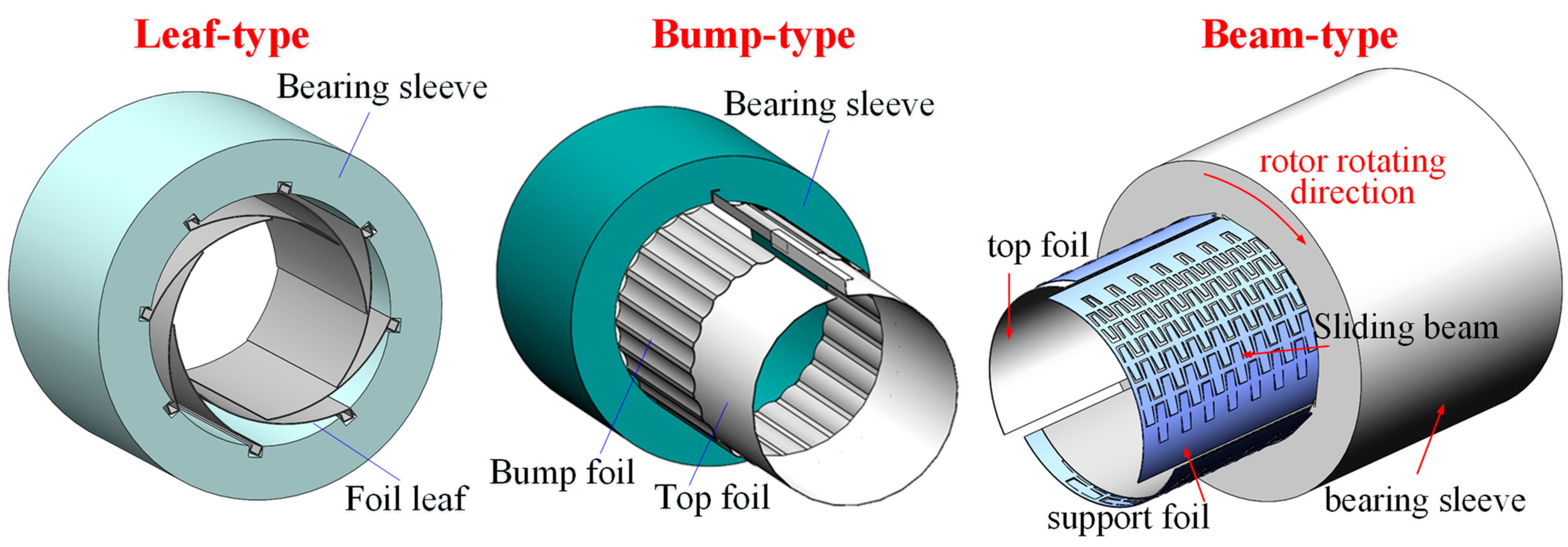
Figure 1. Schematics of the leaf, bump, and beam types of foil bearings.
Lubricants 12 00262 g001
Figure 2. Schematics of the metal mesh, wing foil, and spring types of foil bearings.
Lubricants 12 00262 g002
Figure 3. Experimental test setup functional diagram in [51,52].
Lubricants 12 00262 g003
Figure 4. Bump foil pivot locations and identification of surface contacts in [53].
Lubricants 12 00262 g004
Figure 5. Test setup for dynamic load experiments [55].
Lubricants 12 00262 g005
Figure 6. Test setup for characterizing the static and dynamic properties of the bump foil [57].
Lubricants 12 00262 g006
Figure 7. Calculating algorithms of the dynamic coefficients of a gas foil bearing with contact constraints.
Lubricants 12 00262 g007
Table 1. Dynamic characteristics of different types of GFBs.
Bearing TypeDynamic Characteristics
Leaf foil typeRotor preload effect stabilizing the system [6]; adaption of multi-directional installation and shocking load
Bump foil typeHigh anti-shock ability resulting from the high stiffness bump structure
Beam foil typeThree converged initial clearances stabilizing the rotor; multiple sliding beams providing Coulomb damping [12]; resistance of beam elastic failure
Metal mesh typeHigher loss factor than bump bearing and relatively independent dynamic coefficients with excitation frequency [14]
Wing foil typeLow subsynchronous vibration and good damping through rigid shaft critical speed; extremely tunable design [15]
Isolated spring typeSufficient damping of the underlying structure to effectively suppress maximum peak at the
critical speed rather than the onset of hydrodynamic rotor–bearing instability [16]
Nested spring typeLarger loss factor than the bump foil bearing with similar linear stiffness; larger loss factor than the bearing with isolated springs; larger loss factor under axial preload [17]
Table 2. Key contributions of modeling studies on the foil structural dynamic coefficients of bump-type bearings.
Authors and Publication InformationKey Contributions
Ku and Heshmat [42] A quasi-static enhanced model is developed to calculate hysteresis loops caused by friction in the journal GFBs
Ku and Heshmat [43]The influences of bearing load, load angle, friction coefficient, and dynamic load on dynamic coefficients are investigated
Swanson [44]A simplified model is developed with a single bump and single friction interface as well as the explicit inclusion of a load-dependent friction element
Le Lez and Arghir [45]Friction force is regularized using Petrov’s model; bump motions are investigated in one loading cycle of one bump and of multiple bumps in a strip
Feng et al. [47]A LuGre dynamic friction model is applied, and loading–unloading simulations are conducted on both a six-bump strip and a full bearing
Hoffmann et al. [49]The influence of mechanical preload induced by metal shims is investigated
Zywica et al. [50]Abaqus commercial software is used, and the influence of assembly preload is studied
Table 3. Key contributions of experimental studies on the foil structural dynamic coefficients of bump-type bearings.
Authors and Publication InformationKey Contributions
Ku and Heshmat [51] A test facility using two shakers on a full bearing was built for the first time, and algorithms of calculating dynamic coefficients from test data are presented
Ku and Heshmat [52]Direct stiffness and damping coefficients in a gas foil bearing are found to increase with static load through experiments
Ku and Heshmat [53]A test facility was built to study the influence of load distributions, friction coefficients, surface coatings, and lubricants on dynamic coefficients
Salehi and Heshmat [54]Semi-empirical functions of the dynamic damping and friction coefficients were developed, and high-ambient temperature and vapor conditions were considered
Rubio and San Andres [55]The dry friction coefficient was identified, and comprehensive investigations including various parameters were conducted
Kim and Breedlove [56]The influence of temperature on the dynamic coefficients of foil structures were experimentally investigated
Larsen et al. [57]The flatten phenomenon of hysteresis loops under higher excitation frequency were found, and reasonable explanations were presented
Table 4. Key contributions of aeroelastic dynamic coefficients studies on gas or gas foil bearings.
Authors and Publication InformationKey Contributions
Lund [61]A perturbation method for calculating dynamic coefficients in gas bearings was developed for the first time
Peng and Carpino [62]A perturbation method was applied in gas foil bearing for the first time, and aeroelastic dynamic coefficients were calculated
Peng and Carpino [63]Viscous damping was introduced to equivalent Coulomb friction damping
Peng and Carpino [64]Real foil configuration was considered in the perturbation method of gas foil bearings
Carpino and Talmage [65]Real foil configuration was considered, and the influences of orbit size et al. were studied
Howard et. al [66]The influence of temperature on aeroelastic dynamic coefficients was studied
Kim [67]The perturbation and orbit methods were compared in terms of predicting rotor instability speed, and the influence of mechanical preload (3-pad structure) was investigated
Larsen et al. [68]Errors between perturbation and orbit methods were found, and possible reasons were proposed by stating that the error tends to increase with the decrease in foil stiffness
Osmanski et al. [69]Three approaches were adopted to predict the linear rotor instability supported by gas foil bearings: classical perturbation, extended perturbation, and the Jacobian eigenvalue
Pronobis and Liebich [70]A revised foil structural perturbation model was developed by taking the self-excitated eigenfrequent vibration into account
Hoffmann et al. [71]Close calculation results of perturbation and orbit methods were obtained, and the influences of bump pad number and metal shim on dynamic coefficients were studied
Gu et al. [72]A perturbed finite element model of complex foil structures was developed, and close calculation results of perturbation and orbit methods were also obtained
Zhou and Gu et al. [73]The multi-mode problem was solved by applying an s-domain (complete frequency domain) impedance
Bonello and Pham [74]A method using eigenvalues extracted from the Jacobian matrix for predicting the static equilibrium stability of gas foil bearing was proposed for the first time
Bonello [75]Campbell maps with whirl modes and mode-specific initial conditions were presented
Bonello [76]The detachment of top foil from the bump foil in the dynamic model was considered to enable this frequency method to be more robust
Bonello et al. [77]Two alternative approaches were adopted to conduct a linearized analysis
Li et al. [78]A perturbed model of the complex foil structure with contact constraints was developed, and calculating algorithms for the dynamic coefficients were proposed for the complex model
Table 5. Key contributions of nonlinear rotor dynamic studies on gas foil bearings.
Authors and Publication InformationKey Contributions
San Andres et al. [82]0.5 × rotor subsynchronous vibration was found to increase with unbalance level
San Andres et al. [83]The whirl frequency ratio tended to bifurcate from one-half to one-third as rotor speed increases, similar to a Duffing oscillator with multi-frequency responses
Balducchi et al. [84]Larger rotor speed and unbalance could excite more components of subsynchronous vibrations, including frequency-locked ones and nonlinear jump phenomena
Guo et al. [85]Larger bearing radial clearance led to larger amplitudes of both synchronous and subsynchronous vibrations
Guo et al. [86]Definitions of whip and whirl components of nonlinear rotor vibration supported by gas foil bearings were proposed
Guo et al. [87]Higher levels of static and unbalance loads could increase the subsynchronous vibrations
Le Lez and Arghir [88]A transient model of the foil structure was developed, and larger rotor unbalance could lead to a nonlinear jump
Iordanoff [89]An optimal friction coefficient value exists for ensuring the best stability of the rotor–foil bearing system
Lee et al. [90] A representative study of the weak coupling model was conducted, and optimum values were found for the friction coefficient, bump foil stiffness, and bump foil strips
Bhore et al. [91]The rotor flexibility was considered, and comprehensive simulations of nonlinear rotor dynamics supported by gas foil bearings were conducted, including sufficient bifurcation analyses
Hoffmann et al. [92]The vibration characteristics of high and low balance levels, corresponding to the features of Hopf bifurcation and Duffing system, were found
Bonello et al. [93]A fully coupled dynamic model of the foil bearing–rotor system was established
Bonello et al. [94]The Galerkin method was found to contain fewer state variables and had a higher solving efficiency
Hassan and Bonello [95]The interactions between individual bumps was considered, and a dynamic model of a bump foil strip using modal superposition method was established
Larsen et al. [96]Subsynchronous vibration was found to disappear when the rotor unbalance mass was small and it was different from the traditional linear instability mechanism
Osmanski et al. [97]The theoretical model was found to overestimate the Coulomb damping
Leister et al. [98]Foil structural stiffness was found to have certain influences on rotor instabilities
Table 6. Key contributions of studies on active gas foil bearings.
Authors and Publication InformationKey Contributions
Feng et al. [99]A novel foil bearing with a piezoelectric actuator was proposed to actively adjust the mechanical preload
Guan et al. [100]A larger mechanical preload caused by a higher driven voltage was able to suppress the subsynchronous vibrations through both experiments and simulations
Guan et al. [101]Smaller initial clearance, softer hinge, and larger static load help increase the rotor stability supported by active gas foil bearings
Guan et al. [102]Open-loop and closed-loop controlling methods of active gas foil bearing were proposed
Guan et al. [103]Performance of active bump-metal mesh hybrid foil bearing is investigated
Park et al. [104]A type of active foil bearing was proposed that applied circumferentially distributed piezo stacks to achieve real-time control of the bearing clearance
Sadri et al. [105,106]Piezoelectric patches of the microfiber composite type were applied in combination with the supporting shell to adjust gas foil clearances
Brenkacz et al. [107]Linear displacement actuators for active foil bearings were reviewed
Feng et al. [108]A novel foil bearing using shape memory alloy to actively adjust bearing stiffness and damping was proposed
Disclaimer/Publisher’s Note: The statements, opinions and data contained in all publications are solely those of the individual author(s) and contributor(s) and not of MDPI and/or the editor(s). MDPI and/or the editor(s) disclaim responsibility for any injury to people or property resulting from any ideas, methods, instructions or products referred to in the content.

