Abstract
At high speeds, skew and skid may frequently occur for the rollers in cylindrical roller bearings, especially when under eccentric load, as the uneven load distribution along the generatrix of the roller further aggravates this phenomenon. In this paper, a dynamic model of a cylindrical roller bearing was established, taking into account roller skewing and interactions with the cage. Firstly, the interaction between the roller and the raceway was calculated by slicing the roller along its generatrix. Furthermore, the computation of the interaction between the roller and the cage is based on elastic theory, taking into account pocket clearance. Subsequently, the dynamic equations for both rollers and cage were derived. Based on this foundation, an investigation was conducted to reveal how rotational speed, radial loads, and moment loads affect roller slipping, skewing characteristics, and interactions with the cage under uneven load conditions. The findings indicate a direct proportionality between roller slipping and bearing speed while exhibiting an inverse relationship with load magnitude. Additionally, it was observed that both bearing speed and load have a direct influence on roller skewing angle. Moreover, normal interaction force between the roller and cage demonstrates a direct proportionality to bearing speed while inversely correlating with load magnitude.
1. Introduction
Cylindrical roller bearings play a critical role as foundational components in mechanical equipment, characterized by the line contact between rollers and raceways. They primarily endure radial loads and often operate under uneven load conditions caused by misalignment during assembly and overturning moments during operation. The non-uniform distribution of loads along the roller’s generatrix resulting from this uneven loading leads to issues such as roller skewing, sliding, and frequent impacts with the cage. Therefore, it is imperative to investigate the mechanical characteristics of cylindrical roller bearings under uneven load conditions while considering roller skewing and its internal interactions.
Walters [1] first proposed a dynamic analysis method for ball bearings with four degrees of freedom, utilizing the Runge–Kutta method to solve differential equations and analyzing the transient characteristics of the cage and steel balls. Gupta [2] developed a dynamic model with full degrees of freedom for bearing components, integrating and solving dynamic equations to obtain the time-varying dynamic performance of bearings. However, this approach faces challenges such as strict initial value selection and lengthy computation times. Therefore, Meeks [3,4,5] employed an equivalent interaction between the rolling elements and cage using a spring-damping system, reducing computational complexity and simplifying Gupta’s model.
In terms of ball bearing dynamics, Xi [6] developed a dynamic analysis model for ball bearings, investigating the effects of radial load and inner ring misalignment on the contact characteristics between balls and raceways in angular contact ball bearings. Ye [7] established a dynamic model for ball bearings, analyzing the impact of axial and radial loads during startup on the stability of the cage. Shan [8] introduced a hysteresis damping coefficient into the Hertz contact model to establish a dynamic analysis model for deep groove ball bearings with clearance, studying the effects of clearance on bearing contact and sliding characteristics. Zhao [9] flexibly treated the cage to establish an improved dynamic model for ball bearings, investigating the interaction between balls and the cage. Ye [10] established a four-degree-of-freedom dynamic model for angular contact ball bearing cages, studying the transient characteristics of the cage under axial loads, radial loads, and speed variations.
In the research field of cylindrical roller bearing dynamics, Wang [11] established a dynamic model for cylindrical roller bearings, analyzing the influence of roller profiling on load distribution, roller posture, and contact characteristics. Han [12] proposed a cylindrical roller bearing dynamic model considering radial clearance and roller profiling, analyzing roller slipping behavior under time-varying loads. Chen [13] conducted experimental studies to determine the effects of bearing acceleration and deceleration on the dynamic characteristics of the cage. Liu [14] developed a dynamic model for cylindrical roller bearings by slicing rollers, investigating the impact of non-uniform loads due to gear meshing, rotor eccentricity, and external excitation on bearing life. Gao [15,16,17] studied the effects of axial load, combined loads, cage instability, and roller slipping on the dynamic performance of bearings. Cao [18] investigated the influence of structure and lubrication on bearing motion characteristics under acceleration conditions.
Although extensive research has been conducted on the dynamic characteristics of bearings, the majority of studies have primarily focused on aspects such as the contact between rollers and raceways, roller sliding, and cage slipping under varying conditions. However, there remains a relatively limited amount of research addressing issues like roller slipping, skewing, and roller–cage collisions under uneven load conditions.
Therefore, it is imperative to study the dynamic characteristics of cylindrical roller bearings under uneven load conditions and roller skewing. A dynamic model of cylindrical roller bearings was established, taking into account the effects of roller skewing and its interaction with the cage. The dynamic characteristics of cylindrical roller bearings under uneven load conditions were investigated, which is crucial for the design and prevention of failure in cylindrical roller bearings.
2. Dynamic Model for Cylindrical Roller Bearings
The differential equations of motion for rollers and cages, as well as the static equilibrium equation for the inner ring, are established in this section based on an analysis of the bearing’s movement, relative position, and mechanical relationship of its components [19,20,21]. Furthermore, specific expressions for the interaction forces between parts and the calculation process are provided.
2.1. Coordinates and Fundamental Assumptions
To facilitate the analysis of the motion and force distribution of each component of the bearing, the coordinate system is established as follows:
The origin O of the bearing inertial coordinate system OXYZ is located at the center of the outer race plane. The X-axis aligns with the rotation centerline of the outer race, while the Y-axis is radial. The Z-axis follows the right-hand screw rule to determine its direction, as specifically illustrated in Figure 1. The roller rotation coordinate system oxyz is fixed on the roller, with the origin o located at the centroid of the roller. The x-axis is parallel to the X-axis of the inertial coordinate system, while the y-axis extends outward along the revolution direction of the roller. The roller rotation coordinate system undergoes a rotational motion around the X-axis at a speed corresponding to its revolution rate.

Figure 1.
Cylindrical roller bearing coordinate systems.
The following assumptions are made when establishing the dynamic model of cylindrical roller bearings:
- (1)
- The centroids and geometric centers of all components in the bearing coincide.
- (2)
- All components are rigid bodies, and flexible deformation is not considered.
- (3)
- The outer ring is fixed, the inner ring rotates about its own centroid, rollers revolve about the bearing axis and rotate about their own axes with skewing, and the cage rotates about its own centroid.
- (4)
- The cage pocket shape is rectangular, and the centroids of all bearing components coincide with their centers of mass.
- (5)
- Each individual roller has three degrees of freedom: , , and . These correspond to rotation about the X-axis, rotation about its own axis , and angular displacement due to skewing about the Z-axis .
- (6)
- The cage has a rotational angular displacement about the X-axis .
- (7)
- The cylindrical roller bearing has 3 N + 1 degrees of freedom, where N denotes the total number of rollers; its displacement is denoted as .
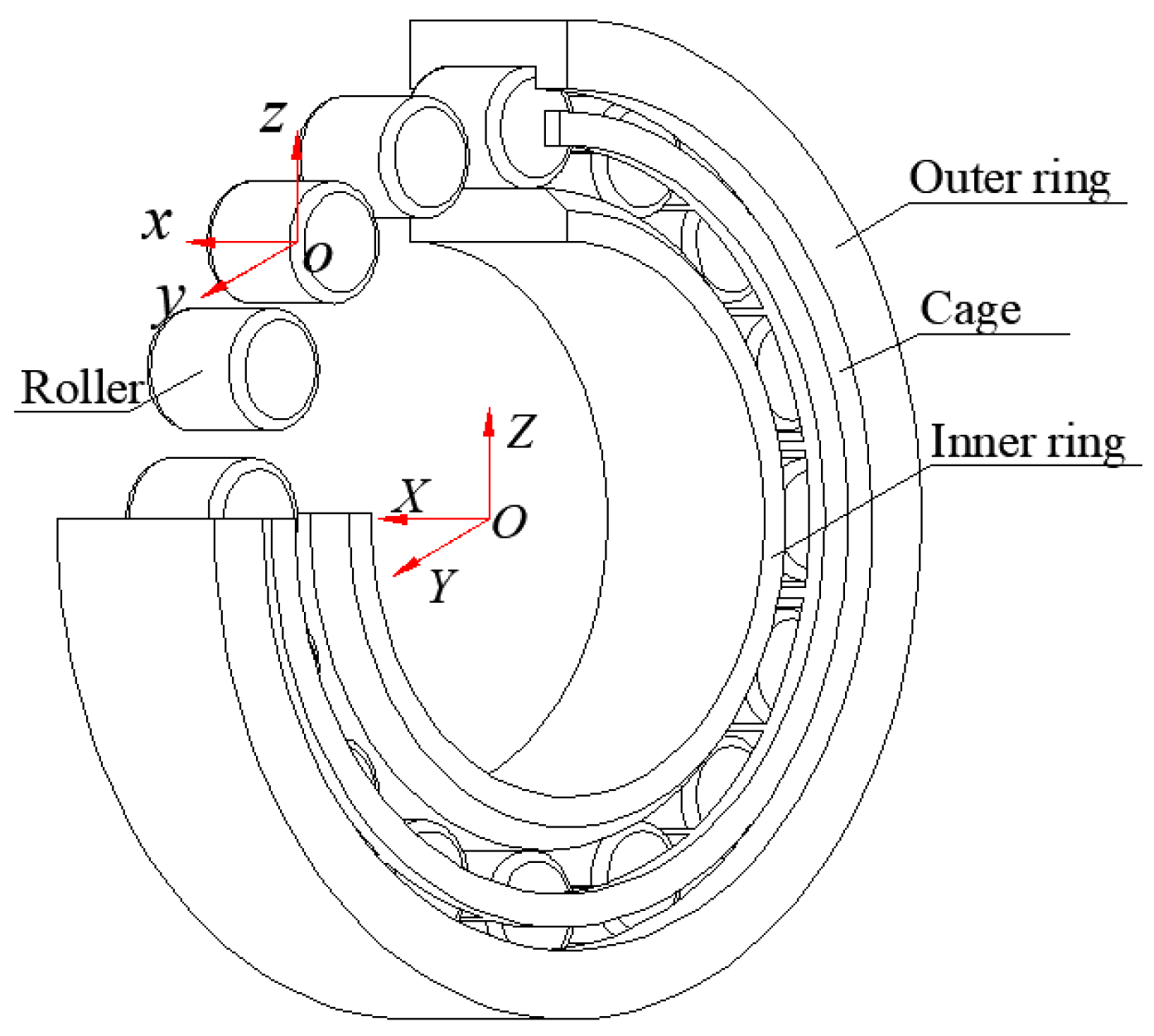
The bearing’s force state is shown in Figure 2. Assuming external forces on the inner ring, the displacement of the inner ring relative to the inertial coordinate system is denoted as .
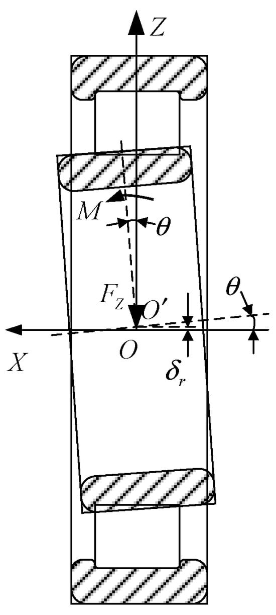
Figure 2.
Loads applied on the bearing.
2.2. Differential Equations of Motion
- (1)
- Roller Motion Differential Equations
The forces exerted on a roller in a cylindrical roller bearing under combined radial and moment loads at a specific moment during operation are illustrated in Figure 3. The roller primarily withstands forces exerted by the inner and outer raceways, the cage, and the resistance of the lubricant.
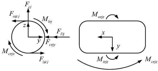
Figure 3.
Load applied to the roller.
The differential equations of the roller are as follows:
where is the diameter of the inner raceway, and are the traction forces exerted on the roller by the inner and outer raceways, is the frictional torque exerted on the roller by the cage around the x-axis, is the rotational resistance torque exerted on the roller by the lubricant [2], are the torques exerted on the roller by the inner and outer raceways around the z-axis direction, is the torque exerted on the roller by the cage around the z-axis, and are the frictional forces exerted on the roller by the inner and outer raceways, is the turbulence resistance of the lubricant to the roller revolution [2], is the torque of the cage on the roller, and are the diameters of the inner and outer raceways, is the diameter of the bearing pitch circle, and , , and are the moment of inertia of the rotation, skew, and revolution of rollers, respectively.
The cage is mainly subjected to the force of rollers and lubricants, and the force is shown in Figure 4. In Figure 4, is the force of the roller on the cage, is the resistance of the lubricant to the cage, and is the revolution speed of the cage.
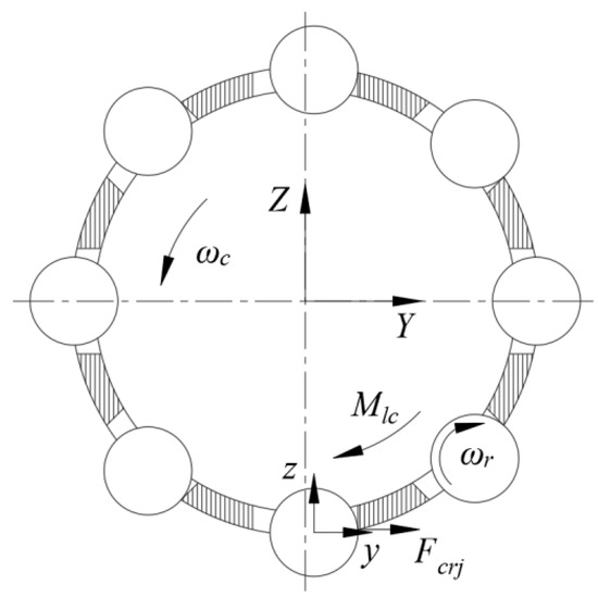
Figure 4.
Load applied to the cage.
The differential equation of cage motion is as follows:
where is the moment of inertia of the cage about the X-axis and is the resistance of the lubricant to the cage.
The analysis process for solving the differential equation of bearing motion begins with the initial determination of the interaction force among bearing internal parts, which is crucial in establishing the initial value for the differential equation.
2.3. Internal Forces
- (1)
- Forces between the roller and the raceway
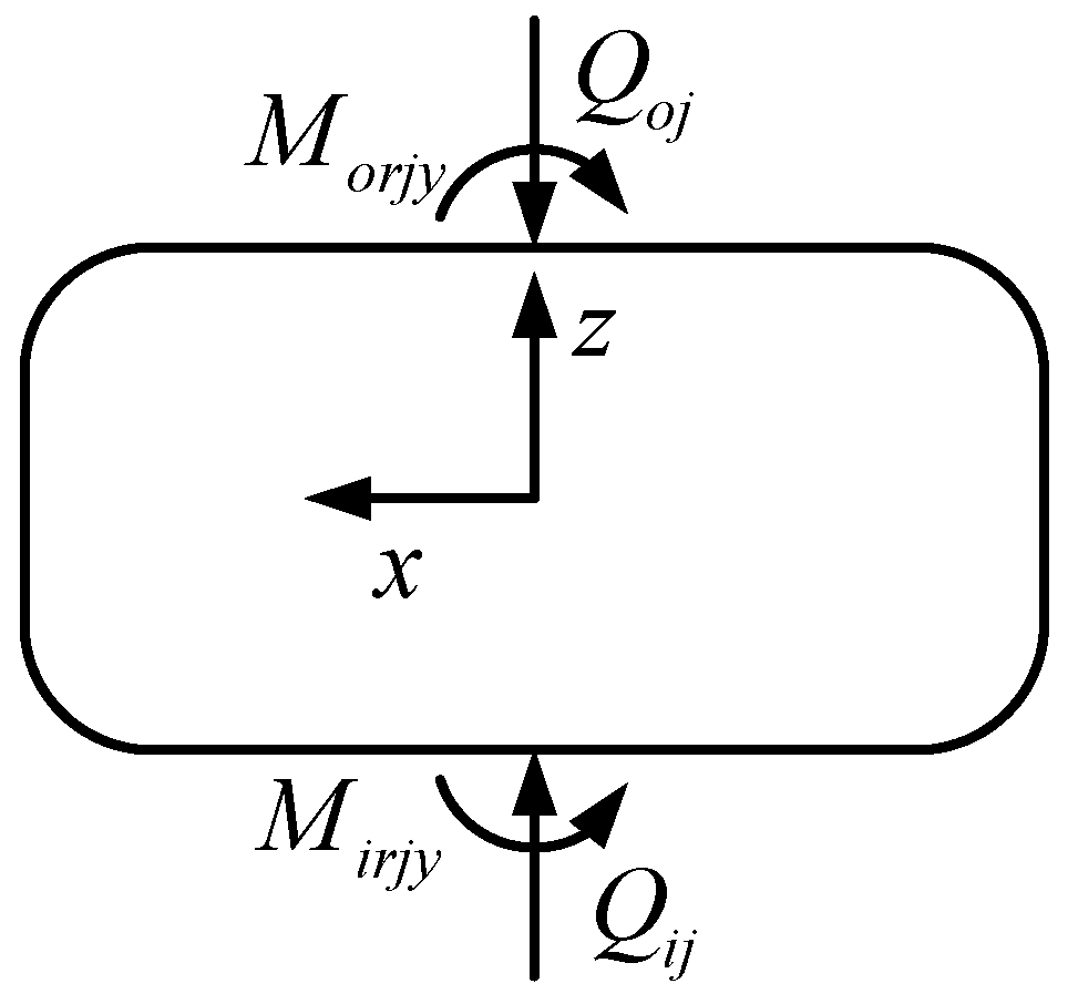
As shown in Figure 5, the static equilibrium equation of the roller’s radial direction is as follows:
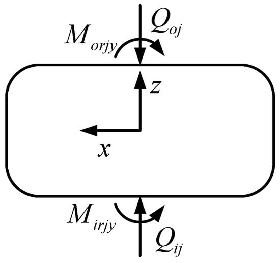
Figure 5.
Static equilibrium of roller.
The balance equation of the roller’s moment around the y-axis is
where and are the contact forces between the inner and outer raceways with the roller, is the centrifugal force on the roller, and and are the deflection torque of the inner and outer raceway to the direction of the roller around the y-axis.
, , , and are generated by the contact between the roller and the inner and outer raceways, and can be obtained by the slicing method [22].
When the radial load and moment act on the cylindrical roller bearing, the inner ring of the bearing will be deflecting, and the roller will be stressed unevenly along the generatrix bar direction.
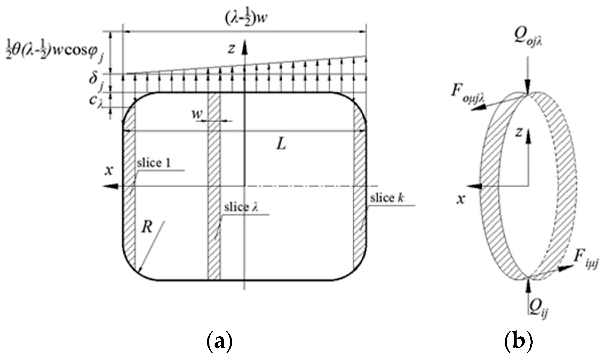
When the roller is divided into k slices along the generatrix direction, the deformation on each slice consists of three parts: deformation caused by radial load at position j, deformation caused by the convexity of the roller at , and deformation of the roller at position j caused by inner ring deflection, as shown in Figure 6a. The contact force between the roller slice and the inner and outer raceway is calculated using the Hertz contact theory, as shown in Figure 6b.
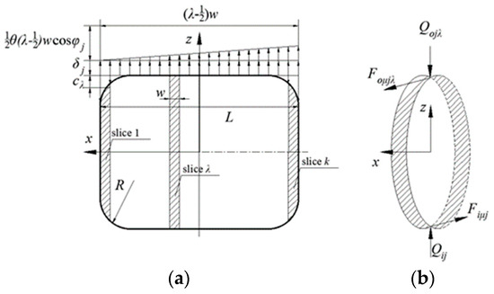
Figure 6.
Schematic diagram of deformation and stress on roller slices. (a) The roller slice is deformed. (b) Roller slices are stressed.
In Figure 6, is the deflection angle of the bearing inner ring, is the length of the roller, is the slice width, , R is the radius of roller repair, is the contact force between the roller slice and the inner raceway, is the contact force between the roller slice and the outer raceway, is the drag force of the inner raceway on the roller slice, and is the drag force of the outer raceway on the roller slice.
According to the analysis in Figure 6, the contact force between a single roller and the inner raceway is as follows:
The contact force between a single roller and the outer raceway is
Due to the uneven force on the roller along the generatrix bar direction, the resulting torques around the y-axis of the roller are
According to the Hertz contact theory, the contact force between the roller slice and the inner raceway is [23]
The contact force between the roller slice and the outer raceway is
where and are the contact deformations between the roller slice and the inner and outer raceways. And , is the combined elastic constant of the two bodies.
where refers to the contact deformation between roller and outer raceway caused by ring deflection and roller modification.
where is the radial clearance of the bearing and refers to the contact deformation between the roller and the inner raceway caused by the deflection of the ring and the modification of the roller [23].
When Equations (5) and (11) are substituted into Equations (3) and (4), a system of static equilibrium equations for 2Z rollers is obtained. This system comprises a total of 2Z + 2 unknowns, including , , , and . To facilitate the numerical solution of this system of equations, the inner race force balance equation is introduced.
where Z is the number of rollers, is the position angle of rollers, and is the eccentricity of the inner raceway of rollers.
The Newton–Raphson method is employed to solve the nonlinear equations, and the contact forces and between each slice of a roller and the inner and outer raceways were obtained.
Due to the role of lubricating oil, the drag force of the inner and outer raceway on the roller slice is
where and are the drag coefficients between roller slices and inner and outer raceways, respectively.
The drag coefficient is determined by the Hertzian contact stress p and slip velocity V at the contact [24]:
where , , , are determined for lubricant properties, , , , .
The slip velocity V is determined by the relationship shown in Figure 7, in which is the inner circle velocity, is the roller’s revolution velocity, and is the roller’s rotation velocity.
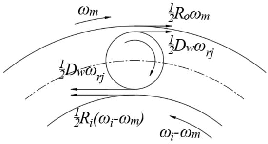
Figure 7.
Roller motion state.
The relative sliding speed of the roller with the inner and outer raceway is
where is the radius of the inner raceway, is the radius of the roller, and is the radius of the outer raceway.
The sliding speed [25] of the slice and ring at angular position j from the center of the roller is
where is the roller skew angle about the z-axis.
- (2)
- Roller and cage interaction
The roller pushes the cage forward in the bearing zone and the roller pushes forward in the non-bearing zone cage. The interaction between the roller and the cage is equivalent to a spring. Due to the gap in the pocket holes, the roller can only contact one side of the cage, which defines that the spring can only be compressed but not stretched. The compression amount of the spring is shown in Figure 8, where the dotted line represents the position of the roller when it is not in contact with the cage, and the solid line represents the position when the roller is in contact with the cage. In the figure, is the rotation angle of the roller and is the rotation angle of the cage.
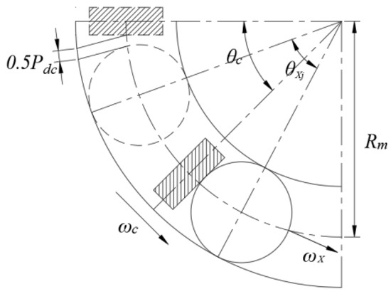
Figure 8.
Spring compression amount.
Due to the deviation of the inner ring, the roller will be skewed due to the different drag force at both ends of the roller. The position relationship between the roller and the cage after the skew is shown in Figure 9.
where and are the spring stiffness of the roller in contact with the cage on the a side and b side, respectively.
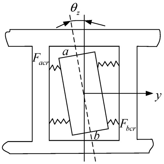
Figure 9.
Position relationship between the roller and the cage after the skew.
The normal force exerted by the cage on the roller can be determined through the aforementioned analysis:
The torque exerted by the cage on the roller is found as follows:
The tangential friction force between the roller and the cage pocket hole is modeled as Coulomb friction force [26], which can be mathematically expressed as follows:
where is the friction coefficient between the roller and the cage, .
is the friction torque of the cage on the roller:
2.4. Calculation Process
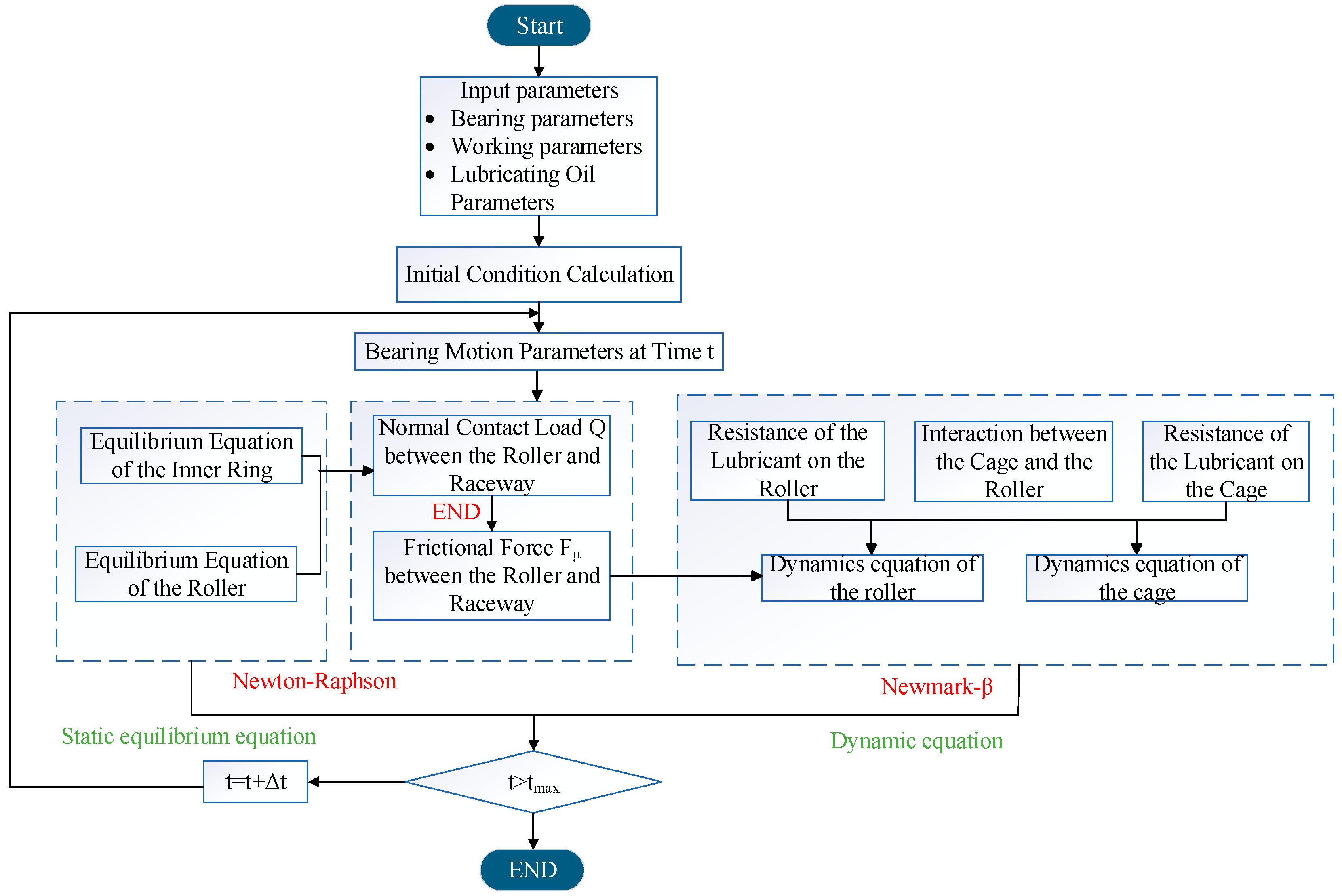
The specific calculation procedure of the dynamic model for cylindrical roller bearings in MATLAB is shown in Figure 10.

Figure 10.
Calculation process.
- (1)
- The initial motion parameter of the bearing is determined by calculating the initial value of the dynamic equation.
- (2)
- The Newton–Raphson method is employed to solve the nonlinear equilibrium equations of the inner ring and the roller, thereby obtaining the contact force between the roller slice and the raceway.
- (3)
- Through the interaction of bearing parts, the drag force of the raceway on the roller, the interaction force between the roller and the cage, and the resistance of the lubricant are obtained.
- (4)
- The aforementioned results are then utilized as initial values in solving dynamics equations for both roller and cage using the Newmark-β method.
2.5. Model Verification
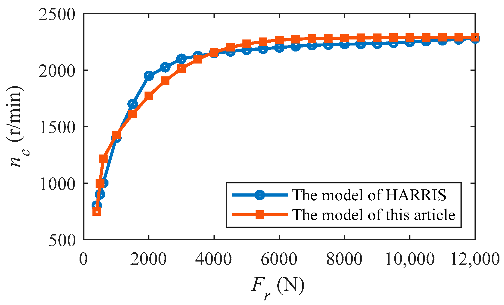
The bearing parameters specified in the Harris model [27] are incorporated into the aforementioned established model, and these parameters are presented in Table 1. By setting the inner ring speed of the bearing to 5000 r/min, we calculate the stable speed of the cage as the radial load varies from 0 to 12,000 N. The corresponding results are illustrated in Figure 11. It is observed that with an increase in radial load, there is a corresponding increase in cage speed until it reaches its maximum value, at which point it remains constant. These findings demonstrate a strong agreement between our proposed model and that of Harris, thereby validating the accuracy of our established model.

Table 1.
Harris model bearing geometric and material parameters.
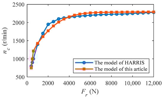
Figure 11.
Cage speed under different loads.
3. Dynamic Characteristics Analysis of Cylindrical Roller Bearing
The analysis of roller slipping and skewing characteristics under eccentric loading conditions necessitates the application of a specific moment load to the bearing while it is subjected to radial load. Hence, in the dynamic model, the radial load FZ is set to 800 N, the moment load M is set to 3 N·m, and the inner race speed n is set at 2000 r/min.
When the roller rotates once around the X-axis, the variation of contact force between each slice and raceway is shown in Figure 12, in which represents the rotation angle of the roller and denotes the section number of the roller along the direction of the generatrix. It is observed that the contact force between the roller and raceway changes with respect to the rotation angle. The maximum contact force occurs when the roller is positioned at the center of the bearing zone (). Specifically, this maximum contact force is present on slice 10 during rotations ranging from 0 to 90° and 270 to 360°. This is due to the linear contact between the roller and raceway, which results in a skewed ring when an unbalanced load is present. As a result, the contact force between the roller and raceway changes along the generatrix direction, leading to an asymmetrical load distribution that causes a large contact force at the heavy end and a small contact force at the light end. The maximum load of the roller along the generatrix bar occurs in slices located at both ends of the roller, with slice 10 experiencing maximum contact force between roller and raceway.
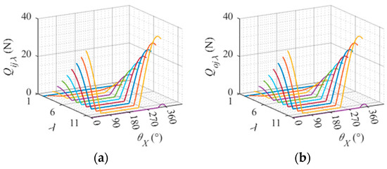
Figure 12.
Contact force between each slice of the roller and the raceway. (a) Contact force between the roller slice and the inner raceway. (b) Contact force between the roller slice and the outer raceway.
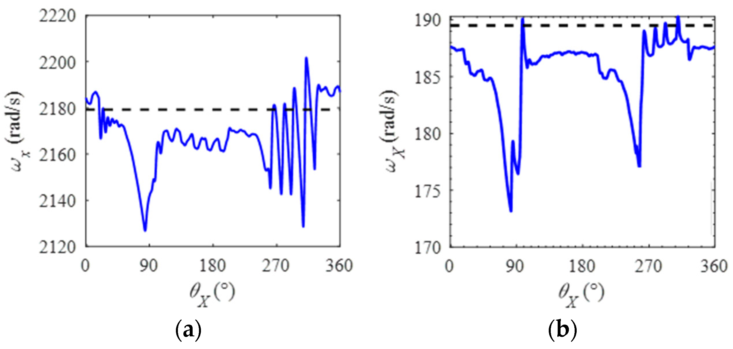
The variations in rotation speed and revolution speed of the rollers are depicted in Figure 13a,b. It can be observed that as the roller moves from the bearing region () towards the non-bearing region (), both rotation and revolution speeds initially remain stable before experiencing a sharp decline. Upon entering the non-bearing region, the rotational velocity and revolution velocity gradually increase to approach the theoretical level, exhibiting fluctuations within a certain range. During the transition from the non-bearing region () to the bearing region (), rotational velocity exhibits steady oscillations followed by a sudden decrease. Once inside the bearing zone, rotation speed rapidly rises to approximate and fluctuate around its theoretical value with a wide range of variation.

Figure 13.
Roller rotation and revolution speed. (a) Roller rotation speed. (b) Roller revolution speed.
The variation of the roller’s skew angle around the z-axis is illustrated in Figure 14. The positive skew angle of the roller, defined as its counterclockwise rotation about the z-axis, exhibits a dependency on its revolution position. As the roller transitions from the loaded region to the non-loaded region, its skew angle remains minimal. However, upon approaching the non-loaded region, clockwise rotation around the z-axis leads to an increase in skew angle, whereas counterclockwise rotation results in a decrease after entering this region. Within the non-load region, clockwise rotation persists until reaching maximum value and stabilizing. Conversely, upon entering the loaded region again, counterclockwise rotation causes an increase in skew angle.
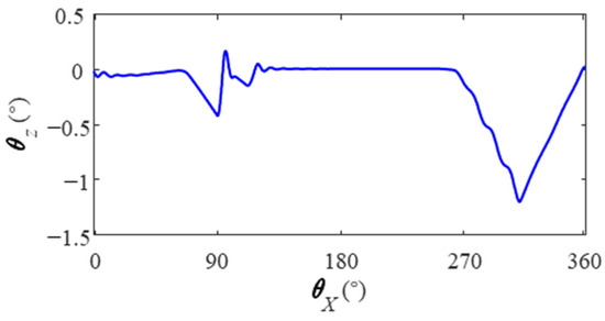
Figure 14.
Roll skew angle.
To further investigate the causes of changes in roller rotation and revolution speed, a plot is presented in Figure 15 illustrating the relative sliding speed of each slice of a single roller over a rotation cycle with the inner and outer raceways. Overall, as the roller transitions from the loaded region () to the non-loaded region (), its relative sliding speed with both raceways initially exhibits steady fluctuations followed by gradual increments. Upon entering the non-loaded region, this relative sliding speed decreases and fluctuates within a specific range.
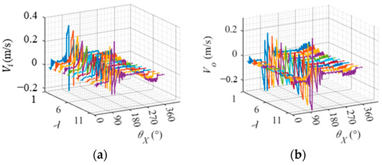
Figure 15.
Relative sliding speed of roller slice and raceway. (a) Relative sliding speed between the roller slice and the inner raceway. (b) Relative sliding speed between the roller slice and the outer raceway.
In the process of transitioning from the non-loaded region () to the bearing region (), there is an initial steady fluctuation followed by a sharp decrease in relative sliding velocities between the inner and outer raceways. Once in the bearing zone (), the relative sliding speed between the roller and raceway decreases and fluctuates sharply within a specific range. The rotation and revolution speed of the roller correspond to changes in relative sliding speed with both raceways, indicating that variations in rotation and revolution speed are caused by changes in relative sliding speed. Relative sliding between the roller and raceway primarily occurs in the transitional region between the bearing region and non-loaded region, where the rotation angle of the roller is close to and . From different slices of rollers, it can be observed that end slices exhibit higher relative sliding speeds with both inner and outer raceways compared to central slices.
In the process of bearing operation, rollers are influenced by both the raceway and cage. To further investigate the factors contributing to changes in the relative sliding speed of rollers, the drag forces exerted by the raceway on roller slices and the normal forces applied by the cage on rollers during rotation are illustrated in Figure 16 and Figure 17. As can be seen from the figure, the roller is located in the center of the bearing zone () towards the non-bearing zone (). During revolution, both the drag force exerted by the raceway on the roller and the force applied by the cage onto it experience an increase.
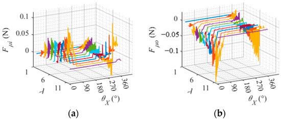
Figure 16.
Drag force of the raceway on the roller slice. (a) Drag force of the inner raceway on the roller slice. (b) Drag force of the outer raceway on the roller slice.
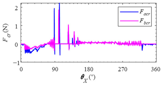
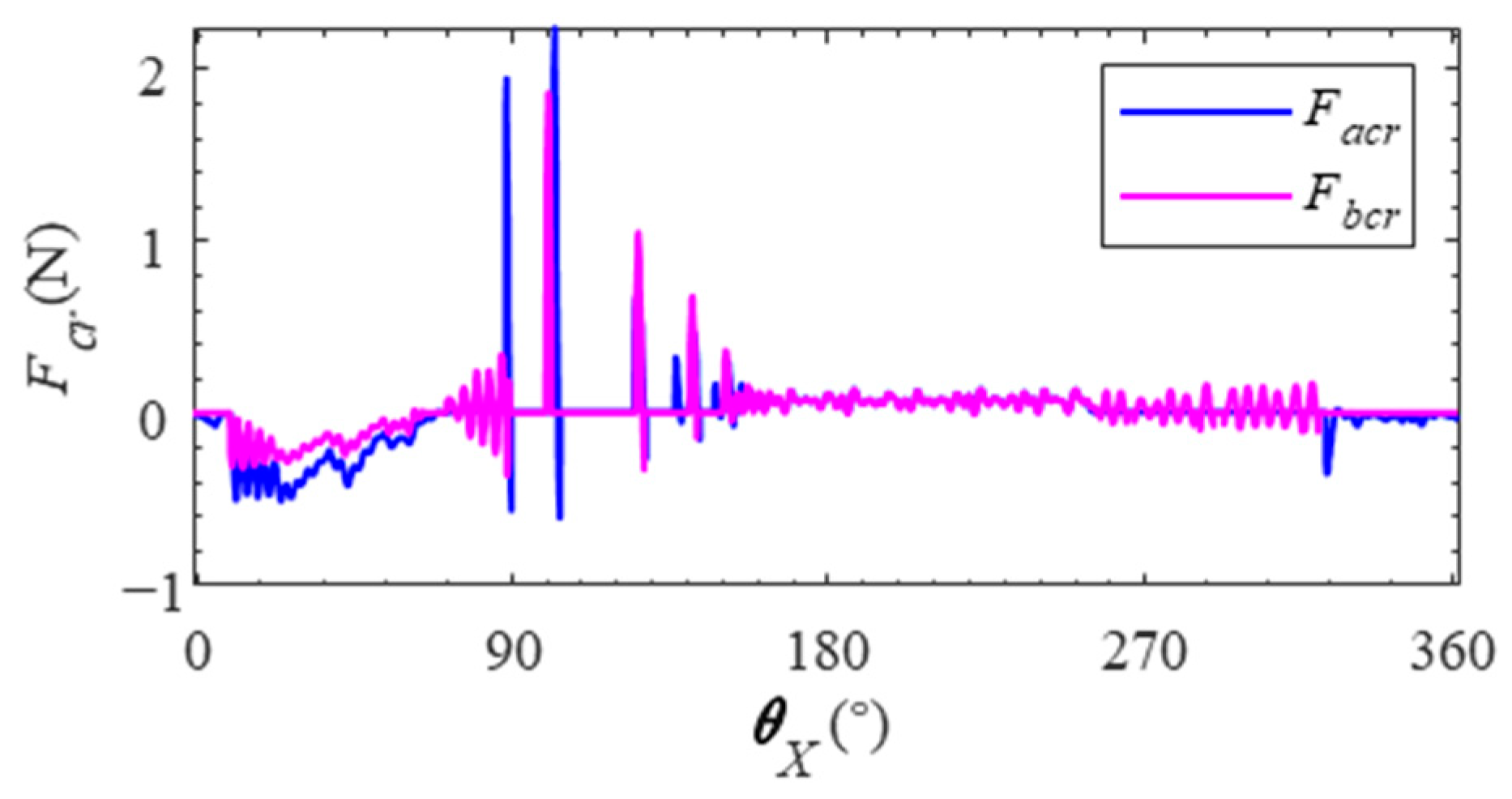
Figure 17.
Normal force applied by the cage on the rollers.
The force exerted by the cage on the roller is opposite to the direction of the roller’s revolution and greater than the drag force of the raceway on the roller. As a result, there is an increase in relative sliding speed between the roller and raceway, leading to a decrease in both the rotation and revolution speed of the roller. Upon entering the non-bearing zone, there is a rapid increase in normal force exerted by the cage on the roller, resulting in an acceleration of both rotation and revolution speed.
During the revolution from the non-bearing zone () to the bearing zone (), the drag force of the raceway on the rollers and the normal force of the cage on the rollers change steadily first. However, as it approaches the boundary of the bearing zone (), there is a sharp increase in the normal force exerted by the cage on the rollers, which simultaneously experience a significant decrease in the drag force exerted on them by the raceway. The relative sliding speed between the roller and the raceway increases, resulting in a decrease in the rotation and revolution speed of the roller. Upon entering the bearing zone (), there is an increase in both the amplitude and fluctuation range of the drag force on the raceway by the rollers, as well as an increase in the normal force exerted by the cage on the rollers. Consequently, there is an increase in both the amplitude and fluctuation range of the relative sliding velocity between the roller and raceway, as well as the rotation and revolution velocity amplitude and fluctuation range of the roller.
The skew of the roller around the z-axis is influenced by the combined effect of the raceway and the cage. As depicted in Figure 16, it can be observed that there is an unequal drag force exerted by the raceway on each section of the roller, resulting in a torque generated by the raceway on the roller around the z-axis. The normal force applied by the cage on the rollers is illustrated in Figure 17. It is evident that there exists a discrepancy in the normal force exerted by both ends of the cage on the rollers, leading to a torque exerted by the cage on the rollers along with their z-axis direction. Consequently, due to this joint action between the raceway and cage, a skew angle about the z-axis direction is induced in the roller.
4. Dynamic Characteristics of Cylindrical Roller Bearing under Unbalanced Load Conditions
Cylindrical roller bearings are mainly used to bear radial load, and under certain conditions there are eccentric load conditions, which will have a direct impact on the dynamic characteristics of the bearing; based on the analysis of the influence of rotational speed and radial load, the influence of the moment load on the dynamic characteristics of the bearing under eccentric load is emphatically analyzed. The bearing structure and material parameters are presented in Table 2.
Table 2.
Structural and material parameters of cylindrical roller bearings.
4.1. Effect of Rotational Speed on Dynamic Characteristics of Cylindrical Roller Bearing
The inner ring speed n was set to 2000 r/min, 6000 r/min, 10,000 r/min, and 14,000 r/min in order to investigate the influence of speed on bearing dynamic characteristics and analyze the dynamic performance of bearings under different inner ring speeds. The radial load was fixed at 800 N, while the torque load remained constant at 3 N·m. The bearing structure and material parameters are presented in Table 2.
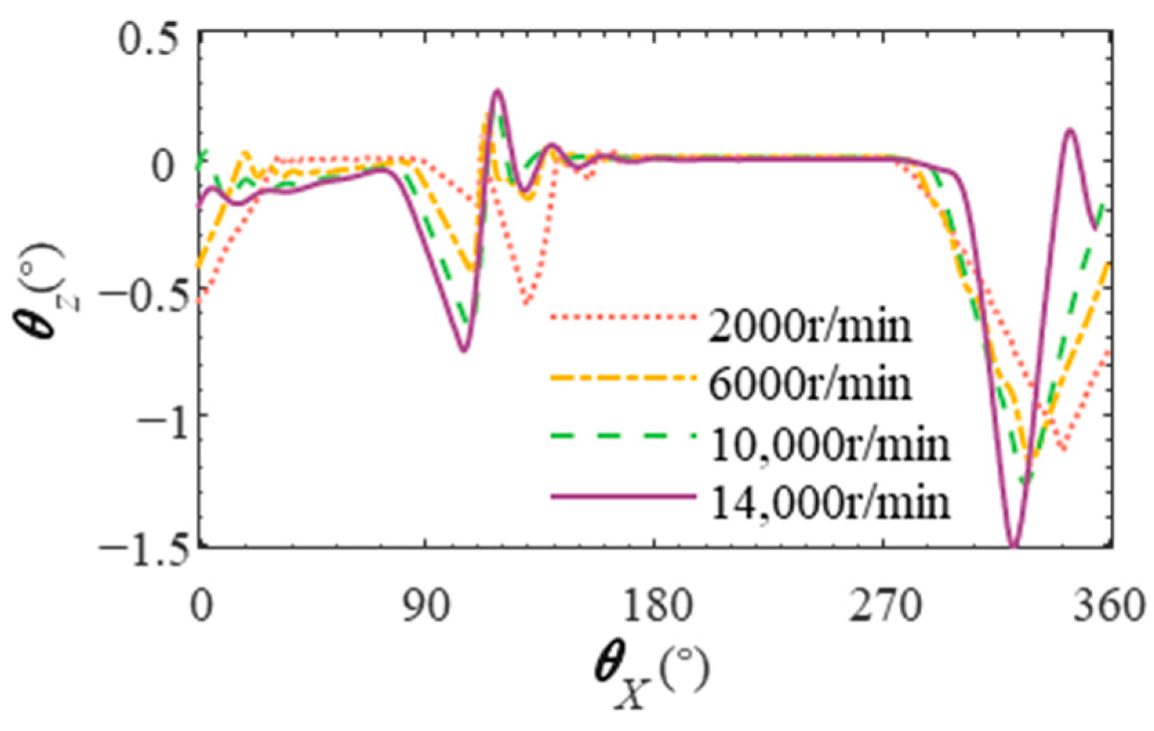
Figure 18 shows the change in the skew angle of the roller during one revolution under different inner ring speeds. The higher the speed of the bearing inner ring, the greater the skew angle amplitude of the roller. This is because the inner ring speed increases, the rotational speed of the roller and the cage increases, the relative speed increases, and the normal force of the cage on the roller (as shown in Figure 19) increases, making the skew angle of the roller larger.
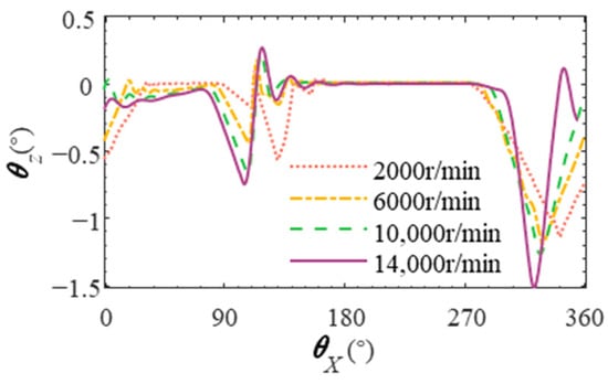
Figure 18.
Deflection angle of the roller at different rotational speeds.
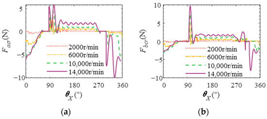
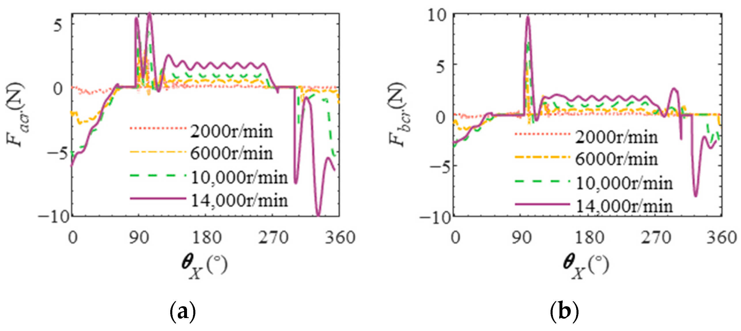
Figure 19.
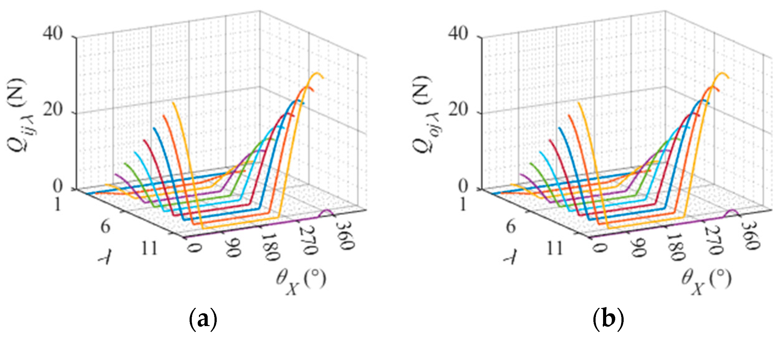
Normal force of the cage on the roller at different rotational speeds. (a) Normal force of the cage on roller point a. (b) Normal force of the cage on roller b.
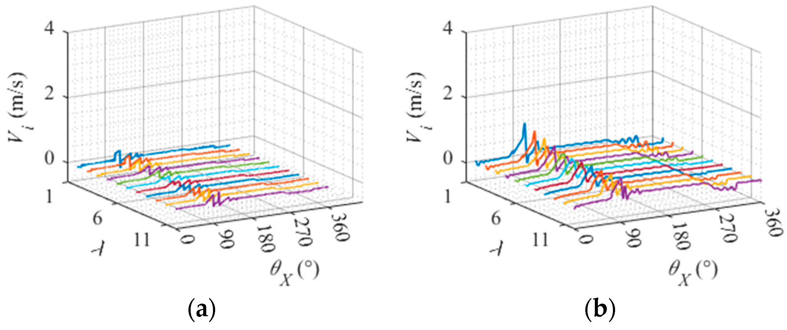
The relative sliding speed between the roller slice and the inner raceway at different inner ring speeds is shown in Figure 20. The different colored curves in the figure represent the different slices of the roller. Overall, the higher the inner ring speed, the greater the relative sliding speed between the roller and the inner raceway. From the different slices of rollers, the higher the inner ring speed, the greater the distance from the center of the roller and the relative sliding speed between the slice and the inner raceway.
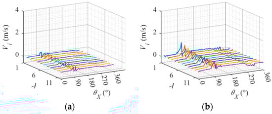
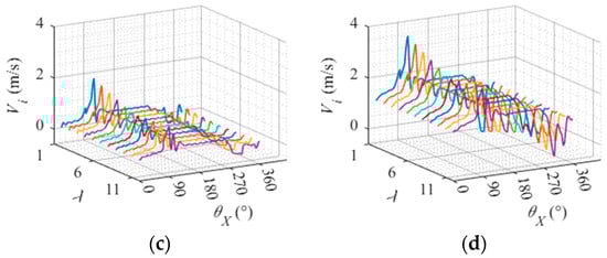
Figure 20.
Relative sliding speed between roller slice and inner raceway at different rotational speeds. (a) Inner ring speed 2000 r/min. (b) Inner ring speed 6000 r/min. (c) Inner ring speed 10,000 r/min. (d) Inner ring speed 14,000 r/min.
4.2. Effect of Torque Load on Dynamic Characteristics of Cylindrical Roller Bearing
The torque load on the bearing was varied to investigate its influence on the dynamic characteristics and analyze the dynamic performance under different loads. Specifically, four torque loads M were applied: 0 N·m, 3 N·m, 5 N·m, and 10 N·m. The inner ring speed was set at 6000 r/min, and a radial load of = 400 N was applied.
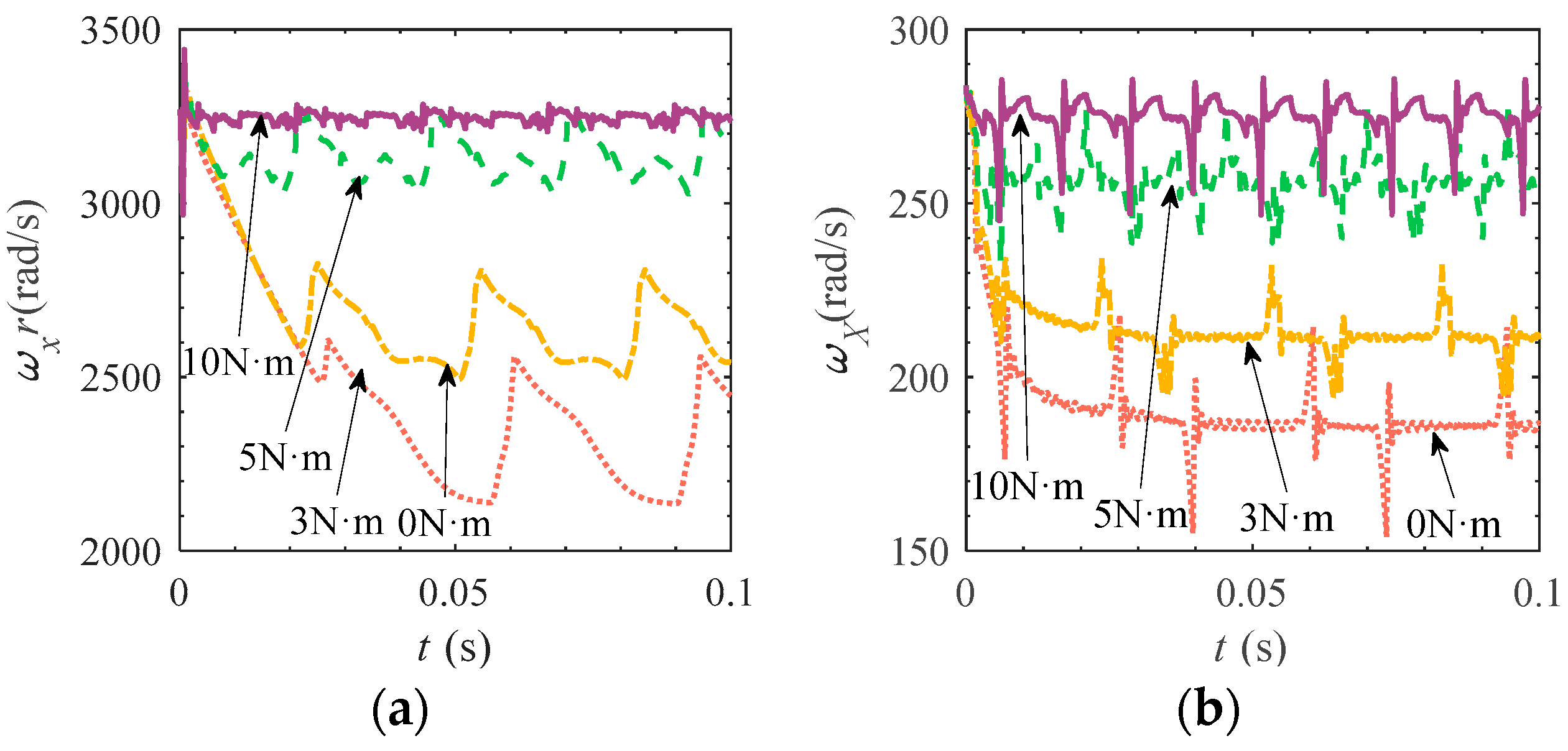
The rotation and revolution speed of rollers under different torque loads are shown in Figure 21. It can be seen that the rotation and revolution velocities of rollers with larger torque loads are larger, and the fluctuation range is smaller and the frequency is larger. This is because the greater the torque load, the greater the contact load between the roller and the raceway, and the smaller the degree of slip between the raceway.
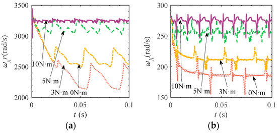
Figure 21.
Roller rotation and revolution speed under different torque loads. (a) Roller rotation speed. (b) Roller revolution speed.
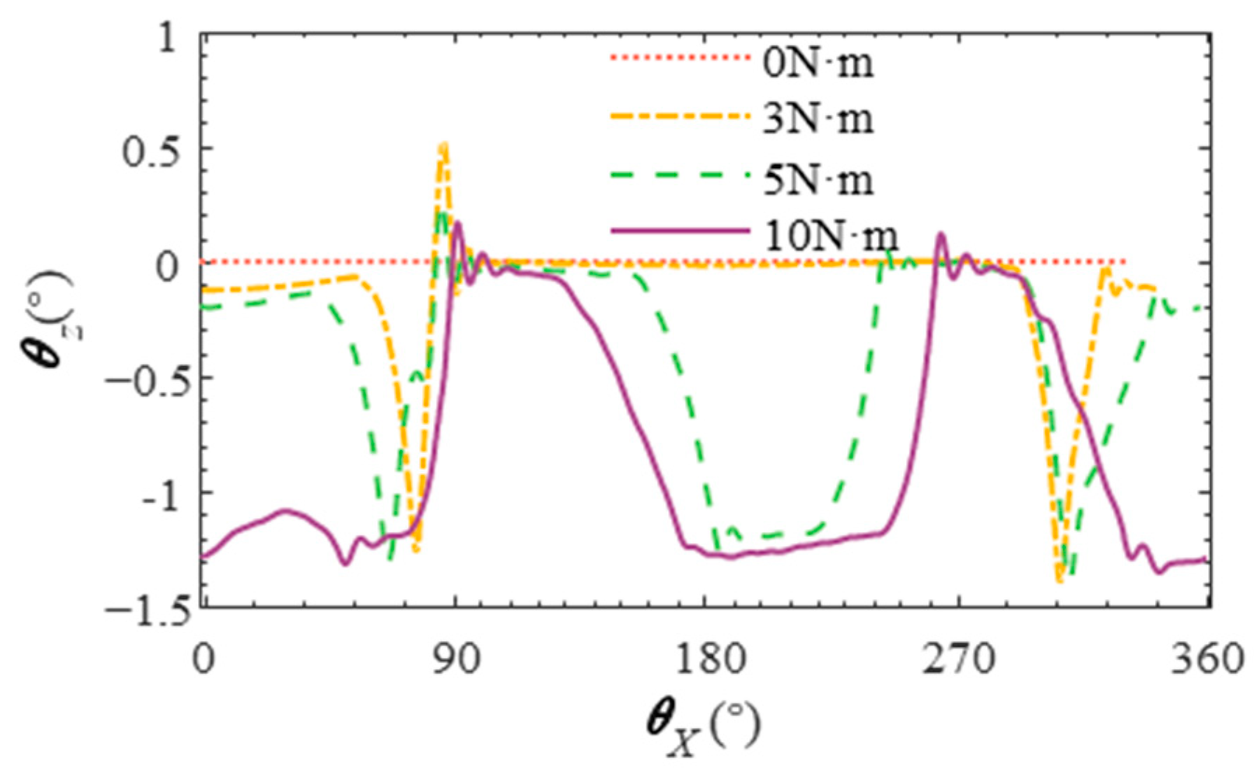
Figure 22 shows the influence of different torque loads on the skew angle of rollers. It can be seen that the greater the torque load, the greater the roller skew angle and the greater the skew range. Figure 23 shows the normal force of the cage on the roller under different torque loads. It can be seen that the greater the torque load, the greater the normal force of the cage on the roller, and the smaller the frequency of action. This is because the increase in torque load and the increase in the contact load between the roller and the raceway aggravate the biased load effect, and as the difference between the drag force of the inner raceway and the different slices of the roller increases, the larger the drag force of the slice with the larger distance from the center of the roller, the larger the torque of the raceway to the roller in the z-axis, and the larger the skew angle of the roller, and because the normal force of the cage on the roller decreases. The frequency of action is reduced, and the frequency of the roller skew angle fluctuation is reduced.

Figure 22.
Deflection angle of rollers under different torque loads.
Figure 23.
Normal force of cage on roller under different torque loads. (a) Roller rotation speed. (b) Roller revolution speed.
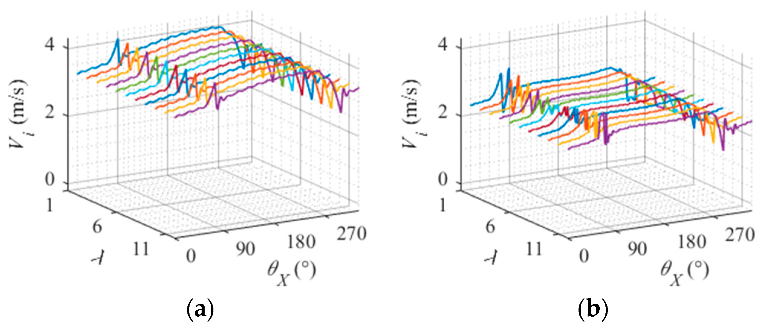
Figure 24 illustrates the variation in relative sliding speed between the roller slice and the inner raceway under different torque loads. The distinct curves of various colors represent different slices of the roller. On the whole, the greater the torque load, the smaller the relative sliding speed between the roller and the inner raceway. This can be attributed to the elevated contact load between them, which hinders roller sliding. Considering different slices of rollers, higher torque loads result in greater disparities among these sections and their respective relative sliding speeds with respect to the inner raceway. This is due to an augmented skew angle of the roller caused by increased torque load, leading to amplified differences in relative sliding speeds between various slices of the roller and its corresponding inner raceway.
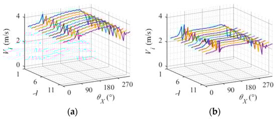
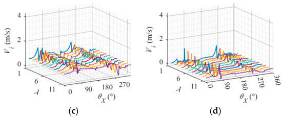
Figure 24.
Relative sliding velocity between the roller slice and inner raceway under different torque loads. (a) Torque load 0 N·m. (b) Torque load 3 N·m. (c) Torque load 5 N·m. (d) Torque load 10 N·m.
5. Conclusions
To investigate the dynamic behavior of cylindrical roller bearings with roller skew under eccentric load conditions, a dynamic analysis model was developed that takes into account roller skew and cage interaction. The model was used to investigate the impact of rotational speed, radial load, and torque load on the dynamic characteristics of the bearings. Based on the analysis conducted, the following conclusions can be drawn:
- (1)
- The increase in rotational speed leads to a rise in the relative sliding speed between the roller and the raceway, resulting in a higher skew angle and an augmented normal force exerted by the cage on the roller. Moreover, this also amplifies the disparity in relative sliding speeds between different slices of rollers and raceway, as well as intensifies the variation in drag forces experienced by different sections of rollers on the raceway.
- (2)
- The relative sliding speed between the roller and raceway decreases as the radial load increases, leading to a decrease in skew angle and the normal force of the cage on the roller. Additionally, there is a reduction in the relative sliding speed difference between different roller slices and raceway, as well as a decrease in drag force difference between the raceway and different roller slices.
- (3)
- When the torque load increases, the relative sliding speed between the roller and the raceway decreases, resulting in an increase in skew angle and a decrease in the normal force of the cage on the roller. Additionally, there is an increased difference in relative sliding speed between different slices of rollers and the raceway, as well as an increased difference in drag force between different slices of rollers on the raceway.
Author Contributions
Conceptualization, Y.Y.; methodology, Y.Y.; software, J.W.; validation, B.W.; formal analysis, Y.Y.; investigation, J.W.; resources, Y.Y.; data curation, B.W.; writing—original draft preparation, M.W.; writing—review and editing, J.W.; visualization, J.W.; supervision, B.W.; project administration, B.W.; funding acquisition, B.W. All authors have read and agreed to the published version of the manuscript.
Funding
This work was financially supported by the Natural Science Foundation of Liaoning Province (2023-MS-280) and the Scientific research project of Education Department of Liaoning Province (LJKMZ20220864).
Data Availability Statement
Restrictions apply to the datasets.
Conflicts of Interest
Author Yang Yang was employed by the China North Vehicle Research Institute. The remaining authors declare that the research was conducted in the absence of any commercial or financial relationships that could be construed as a potential conflict of interest.
References
- Walters, C.T. The Dynamics of Ball Bearings. J. Lubr. Technol. 1971, 93, 1–10. [Google Scholar] [CrossRef]
- Gupta, P.K. Dynamics of Rolling-Element Bearings—Part I: Cylindrical Roller Bearing Analysis. J. Lubr. Technol. 1979, 101, 293–302. [Google Scholar] [CrossRef]
- Meeks, C.R. The dynamics of ball separators in ball bearings—Part II: Results of optimization study. ASLE Trans. 1985, 28, 288–295. [Google Scholar] [CrossRef]
- Meeks, C.R.; Ng, K.O. The dynamics of ball separators in ball bearings—Part I: Analysis. ASLE Trans. 1985, 28, 277–287. [Google Scholar] [CrossRef]
- Meeks, C.R.; Tran, L. Ball Bearing Dynamic Analysis Using Computer Methods—Part I: Analysis. J. Tribol. 1996, 118, 52–58. [Google Scholar] [CrossRef]
- Xi, H.; Wang, H.Y.; Han, W.; Le, Y.; Xu, H.; Chen, W.; Xu, S.N.; Wang, F.C. Contact trajectory of angular contact ball bearings under dynamic operating condition. Tribol. Int. 2016, 104, 247–262. [Google Scholar] [CrossRef]
- Ye, Z.; Wang, L. Effect of external loads on cage stability of high-speed ball bearings. Proc. Inst. Mech. Eng. Part J J. Eng. Tribol. 2015, 229, 1300–1318. [Google Scholar] [CrossRef]
- Shan, W.; Chen, Y.; Wang, X.; Yu, C.; Wu, K.; Han, Z. Nonlinear Dynamic Characteristics of Deep Groove Ball Bearings with an Improved Contact Model. Machines 2023, 11, 340. [Google Scholar] [CrossRef]
- Zhao, D.; Hong, J.; Yan, K.; Zhao, Q.; Fang, B. Dynamic interaction between the rolling element and cage of rolling bearing considering cage flexibility and clearance. Mech. Mach. Theory 2022, 174, 104905. [Google Scholar] [CrossRef]
- Ye, Z.H.; Wang, L.Q. Cage Instabilities in High-Speed Ball Bearings. Appl. Mech. Mater. 2013, 278–280, 3–6. [Google Scholar] [CrossRef]
- Wang, Z.; Song, J.; Li, X.; Yu, Q. Modeling and Dynamic Analysis of Cylindrical Roller Bearings Under Combined Radial and Axial Loads. J. Tribol. 2022, 144, 121203. [Google Scholar] [CrossRef]
- Han, Q.; Li, X.; Chu, F. Skidding behavior of cylindrical roller bearings under time-variable load conditions. Int. J. Mech. Sci. 2018, 135, 203–214. [Google Scholar] [CrossRef]
- Chen, S.; Chen, X.; Li, Q.; Gu, J. Experimental Study on Cage Dynamic Characteristics of Angular Contact Ball Bearing in Acceleration and Deceleration Process. Tribol. Trans. 2021, 64, 42–52. [Google Scholar] [CrossRef]
- Liu, Y.; Chen, Z.; Wang, K.; Zhai, W. Non-uniform roller-race contact performance of bearings along width in the rotor-bearing system under dynamic loads. J. Sound Vib. 2022, 538, 117251. [Google Scholar] [CrossRef]
- Gao, S.; Wang, L.; Zhang, Y. Modeling and dynamic characteristic analysis of high speed angular contact ball bearing with variable clearance. Tribol. Int. 2023, 182, 108330. [Google Scholar] [CrossRef]
- Gao, S.; Han, Q.; Zhou, N.; Pennacchi, P.; Chatterton, S.; Qing, T.; Zhang, J.; Chu, F. Experimental and theoretical approaches for determining cage motion dynamic characteristics of angular contact ball bearings considering whirling and overall skidding behaviors. Mech. Syst. Signal Process. 2022, 168, 108704. [Google Scholar] [CrossRef]
- Gao, S.; Chatterton, S.; Pennacchi, P.; Han, Q.; Chu, F. Skidding and cage whirling of angular contact ball bearings: Kinematic-hertzian contact-thermal-elasto-hydrodynamic model with thermal expansion and experimental validation. Mech. Syst. Signal Process. 2022, 166, 108427. [Google Scholar] [CrossRef]
- Cao, W.; Wang, J.; Pu, W.; Zhang, Y.; Wu, J.; Chu, K.; Wu, H. A study on the effect of acceleration on slip velocity and lubrication performance in cylindrical roller bearings. Proc. Inst. Mech. Eng. Part J J. Eng. Tribol. 2016, 230, 1231–1243. [Google Scholar] [CrossRef]
- Prisacaru, G.; Bercea, I.; Cretu, S.; Mitu, N. Load distribution in a cylindrical roller bearing in high speed and combined load conditions. Eur. J. Mech. Eng. 1995, 40, 19–25. [Google Scholar]
- Kabus, S.; Hansen, M.R.; Mouritsen, O.Ø. A New Quasi-Static Cylindrical Roller Bearing Model to Accurately Consider Non-Hertzian Contact Pressure in Time Domain Simulations. J. Tribol. 2012, 134, 041401. [Google Scholar] [CrossRef]
- Chen, H.; Zhang, H.; Liang, H.; Wang, W. The collision and cage stability of cylindrical roller bearing considering cage flexibility. Tribol. Int. 2024, 192, 109219. [Google Scholar] [CrossRef]
- de Nul, J.M.; Vree, J.M.; Maas, D.A. Equilibrium and Associated Load Distribution in Ball and Roller Bearings Loaded in Five Degrees of Freedom While Neglecting Friction—Part II: Application to Roller Bearings and Experimental Verification. J. Tribol. 1989, 111, 149–155. [Google Scholar] [CrossRef]
- Harris, T.A.; Kotzalas, M.N. Rolling Bearing Analysis—2 Volume Set; CRC Press: Boca Raton, FL, USA, 2006. [Google Scholar]
- Wang, Y.; Zhang, G.; Wang, E. Traction Behavior of No. 4129 Synthetic Oil for Space Lubrication. J. Fail. Anal. Prev. 2019, 19, 138–143. [Google Scholar] [CrossRef]
- Cui, Y.; Deng, S.; Yang, H.; Zhang, W.; Niu, R. Effect of cage dynamic unbalance on the cage’s dynamic characteristics in high-speed cylindrical roller bearings. Ind. Lubr. Tribol. 2019, 71, 1125–1135. [Google Scholar] [CrossRef]
- Tu, W.; Liang, J.; Yu, W.; Shi, Z.; Liu, C. Motion stability analysis of cage of rolling bearing under the variable-speed condition. Nonlinear Dyn. 2023, 111, 11045–11063. [Google Scholar] [CrossRef]
- Harris, T.A. An Analytical Method to Predict Skidding in High Speed Roller Bearings. ASLE Trans. 1966, 9, 229–241. [Google Scholar] [CrossRef]


Disclaimer/Publisher’s Note: The statements, opinions and data contained in all publications are solely those of the individual author(s) and contributor(s) and not of MDPI and/or the editor(s). MDPI and/or the editor(s) disclaim responsibility for any injury to people or property resulting from any ideas, methods, instructions or products referred to in the content. |
© 2024 by the authors. Licensee MDPI, Basel, Switzerland. This article is an open access article distributed under the terms and conditions of the Creative Commons Attribution (CC BY) license (https://creativecommons.org/licenses/by/4.0/).