Abstract
Machine tool vibrations play a significant role in hindering productivity during machining. The growing vibrations accelerate tool wear and chipping, cause a poor wave surface finish, and may damage the spindle bearing. Some research showed that tribological properties such as friction factors can have obvious influences on the topography of rough surfaces and the nonlinear dynamic characteristics of machine tool systems. Therefore, studying the vibration friction dynamic characteristics on the normal contact stiffness (NCS) of joints of CNC machine tools is absolutely necessary for improving the machining accuracy and precision of the whole system. The study results of NCS of joints of the CNC and the friction coefficient are discussed in this paper. The model of NCS based on fractal parameters was obtained. The models of deformations of the rough surfaces and contact surfaces were deduced. The results showed that the NCS based on the calculation method considering the elastic–plastic deformation of the asperity is much higher in precision than the methods considering only elastic or plastic deformation separately. The observations this paper described suggest that in the CNC machine tools system, higher D and G and higher friction coefficients lead to higher normal contact stresses (NCSs).
MSC:
74H45
1. Introduction
A machine tool is a composite structure mainly composed of components such as the bed, column, spindle box, guide rail, workbench, etc. The surface where these components come into contact with each other is the machine tool joint. In the static and dynamic analysis of machine tools, the joints often cause damage to the continuity of the mechanical structure of the machine tool, making its static and dynamic characteristics more complex. Many studies show that the joints have a significant impact on the dynamic characteristics of the machine tools, of which more than 60% of the vibration problems of the machine tool originate from the joints, and the NCS of the joints accounts for about 60% to 80% of the total stiffness of the machine tools [1,2]. Hence, studying reasonable calculation methods and setting up accurate models of the various joints of the machine tools can greatly improve the accuracy of static and dynamic simulation analysis of the machine tools, laying a good foundation for subsequent dynamic stiffness analysis and optimization of the entire machine.
The joints in CNC machine tools mainly include the fixed joints and the movable joints. The fixed joints mainly play a significant role in connecting various components of the machine tool, accounting for a large proportion of the machine tool joint. It mainly includes the bed column joint parts, the bed body and column guide rail joint parts, the guide slide and slide plate workbench joint parts, the screw nut and workbench joint parts, the bearing seat and motor seat bed body joint parts, etc. Therefore, the fixed joints are the most important joints of the CNC machine tool, and the NCS of the fixed joints profoundly affects the dynamic characteristics of the whole machine. NCS in the joints of CNC machines refers to the resistance of the joints to deformation under an applied normal load. It is a critical factor in the overall performance and accuracy of CNC machines, as it directly affects the machine’s ability to maintain precise positioning and repeatability.
In a CNC machine tool, the joints are where the various components and axes come together to enable movement and operation. These joints can experience significant forces and loads during operation, especially during high-speed machining or when working with harder materials. The NCS ensures that the joints can withstand these forces without deforming, which could lead to errors in the machining process. When a certain load is applied to joints, there is a certain amount of deflection and deformation that occurs. Furthermore, NCS is a measure of how much force is required to cause a certain amount of deflection. A higher NCS means that the joint can resist deformation better, resulting in improved accuracy and repeatability of the CNC machine tools.
However, there are several factors that can affect the NCS of joints in CNC machine tools, including the material properties of the joints’ components, the design and geometry of the joints, the preload or tension in the joints, and the condition of the surfaces in contact components. Proper maintenance and lubrication of joints are also essential to ensure optimal NCS. NCS is a crucial aspect of CNC machine joints that directly impacts the machine’s performance and accuracy. It is important to consider factors such as friction, material properties, joint design, preload, and maintenance to maximize NCS and achieve precise and repeatable machining results. Some researchers developed the calculation methods based on the surface topology of the fixed joints’ contact stiffness. Greenwood and Williamson proposed the elastic contact model of the fixed joints considering surface topography, commonly known as the G–W model [3]. It is known as a statistical contact model. In this model, the contact surface between two joints’ surfaces is considered as the contact of asperities. The radius of each asperity is assumed to be the same, and the height of asperities obeys the Gaussian distribution. Furthermore, Jackson and Green proposed an elastic–plastic contact model to complete the G–W model [4]. Li et al. proposed an improved G–W model considering the bulk substrate deformation and introduced a triangular distribution to the asperities’ height distribution to make the distribution more consistent with the actual surface topology [5]. However, in the G–W model, the height distribution parameters of asperities depend on the sampling size and resolution of the surface profilometer, which indicates that the model is scale-dependent.
In addition, the fractal theory has the advantages of self-affinity and scale independence. Based on fractal theory and Hertz contact theory, Majumdar and Bhushan proposed a fractal contact model (M-B model) to calculate the NCS of the fixed joints [6]. Based on the model, the scale-independent parameters were used to describe the radius and normal deformation of the asperities between two joints’ interfaces. The NCS and contact areas calculated by this model are deterministic. In recent years, many scholars have conducted lots of research on fixed joint stiffness based on the M-B model. Jiang put forward a fractal model to analyze the normal and transitional contact stiffness of the machined joint plane [7]. Zhang took the elastic–plastic deformation stage of asperity into the M-B model and established the calculation method for normal contact stiffness of the joint surface by considering elastic, elastic–plastic, and plastic deformation [8]. Wang et al. studied the fractal contact stiffness model considering the effect of asperity interactions and proposed the concept of fractal smoothness [9]. Chen established a fractal model of normal contact stiffness of spheroidal contact bodies considering friction factors [10]. Chang et al. used the strong contact model to represent the contact force in the plastic zone of the fractal contact model and derived the rotational contact stiffness innovatively, which made the contact model more comprehensive [11]. In order to study the contact stiffness of the dynamic characteristic analysis of the structure, some researchers also focus on the dynamic modeling of the fixed joints. Tian et al. proposed a virtual material method for dynamic modeling of the fixed joint interface of the machine tool [12]. Zhang et al. established a modeling method based on transversely isotropic virtual material [13]. Varga, J et al. proposed a study on the effect of the finishing strategy on surface topography, surface roughness, and variations of machining curved surfaces [14]. However, the limitation of the study was the sample size of the experiment. Because the larger dimensions are used in the machining of molds and some shaped surfaces, this literature offers only a part of the further research. Grešová, Z. et al. investigated the milling of freeform surfaces by a ball-end mill. This literature did not design or verify other methods of detecting shape and surface integrity deviations of finished parts [15]. A Stoica and G Stan studied the ball screw stiffness affection on the positioning accuracy of the feed kinematic linkage of a CNC machine tool [16]. Chen et al. presented a new method to study the static stiffnesses of the ends of a multi-axis machine tool (cutting tool and table). This method was only proper for industrial field conditions in which large and heavy loading equipment was not required [17]. Guzeev et al. researched the CNC machine stiffness. However, each cycle was limited by the requirements in the design method for grinding cycles of circular plunge grinding [18]. Bandara et al. introduced a new experimental stiffness measurement method considering the effect of gravity on the machine tool. The models and gravity effects have been well considered or characterized for PKMs in this literature [19]. Kamboj et al. studied the effect of nanocellulose (CNF and CNC) reinforcement of a polyvinyl acetate (PVAc) adhesive. The work found general trends to be valid for various kinds of CNF and CNC [20]. Guzeev et al. researched the stiffness of the components in a numerically controlled machine tool during inset grinding. The fluctuation in the margin in different machining conditions is determined experimentally [21]. Yang et al. analyzed the disturbance between long and short strokes in detail. The work improved the servo performance of short stroke significantly [22]. Sarhan et al. investigated the characterization of the machine tool spindle stiffness in a radial direction for precise monitoring of cutting forces in the end milling process by using displacement sensors. The work only studied the change in spindle stiffness due to the spindle temperature and the speed [23]. Barkane et al. presented vegetable oil-based resin loaded with lignocellulosic components of cellulose nanocrystals (CNCs), cellulose nanofibers (CNFs), hemicellulose (HC), and lignin (LN) [24]. Liu et al. studied the real contact parameters at a certain angle of inclination. The macro contact angle was first conducted into a micro contact angle according to the stress characteristics, and the deformation of asperities was investigated in the study. However, the stiffness model of the joint surface was conducted based on classification theory [25].
To sum up, some researchers have demonstrated the necessity to calculate the NCS of the fixed joints, and many methods with significant results have been obtained. However, few methods consider the influence of the friction factors, making it unable to reflect the real dynamic characteristics of the joints well. In addition, most methods are verified on specimens rather than the CNC machine tools. It is necessary to verify the feasibility of the calculation method on the CNC machine tools. In this paper, the NCS calculation model based on fractal parameters of joints is set up. Based on this model, the influence of the fractal parameters and the friction coefficient on the NCS of the joints are discussed. This study’s results provide a strong theoretical basis for the subsequent vibration friction characteristic analysis and stiffness optimization on the CNC Machine tool.
2. Models
According to the M-B model, the joint is considered as the two rough surfaces, and the contact of two rough surfaces is considered as an equivalent single rough surface in contact with a rigid smooth plane [26], as shown in Figure 1. The uneven asperities would go through three stages: elastic, elastic–plastic, and plastic deformation based on different contact pressures.
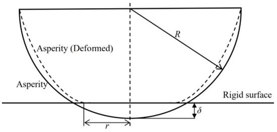
Figure 1.
The contact model of rough surfaces.
When the deformation of two rough surfaces is in the elastic deformation stage, the contact area, contact force, and contact deformation can be deduced by Hertz’s contact theory.
where ae is the contact area, Fe is the contact force of the asperity, R is the radius of the asperity, δ is the elastic deformation of the asperity, and is the equivalent of Young’s module; therefore,
where E and v are, respectively, the Young’s module and Poisson’s ratio of the contact material.
When the deformation comes to the elastic–plastic stage, then the critical deformation δc is
where K is the coefficient of hardness, K = 0.454 + 0.41 v, and v and H are the Poisson’s ratio and the hardness of the softer material of the joints. Hence,
when the δ > 110 δc, the plastic contact area, plastic contact force, and asperity deformation are
For joints, the surface roughness can be characterized by the Weierstrass–Mandelbrot(W-M) fractal function. The height of the surface profile is
where x is the lateral distance of the surface profile, L is the sample length, G is the fractal roughness parameter, D is the fractal dimension (1 < D < 2), γ is the scaling parameter of the spectral density, commonly as 1.5, and φn is the random phase.
Therefore, the deformation of rough surfaces can be expressed as
where a is the cross-sectional area of the rough surfaces, a = πr2.
Then, the radius of the rough surfaces is
According to the M-B model, the area distribution of asperities is considered the same as that of islands on the Earth. Wang and Komvopoulos introduced the domain extension factor ψ in the distribution function of asperities to obtain a much more realistic area distribution [27,28,29,30]. Therefore, the modified area distribution function can be expressed as
The domain extension factor is
In order to distinguish the elastic and plastic deformation stages, elastic critical contact area ac and plastic critical contact area aep can be obtained by Equation (14) and Equation (15). When a < aep, the asperities are in the plastic stage; when aep ≤ a < ac, the asperities are in the elastic–plastic regime; when a ≥ ac, the asperities are in the elastic stage.
Based on Equations (2), (6), (8), (10), and (11), the contact force of asperity in elastic, elastic–plastic, and plastic stages can be derived as
where K is the coefficient of hardness, and v and H are the Poisson’s ratio and the hardness of the softer material of the joints. D is the fractal dimension (1 < D < 2), γ is the scaling parameter of the spectral density, and G is the fractal roughness parameter.
The normal contact load of rough interfaces is obtained for the asperities in each stage; therefore,
where is the normal contact load of rough interfaces, is the friction force, and is the friction coefficient.
The real contact area of rough surfaces can be calculated by integrating the area distribution function of the asperity.
The fractal dimension D and fractal roughness parameter G of the joint surfaces can be obtained by the structure function method. The structure function of the surface profile function is
where τ is the interval in the sampling area, z(x) is the height function of the surface profile, and ⟨⟩ denotes the statistical average of the surface height. C is the sampling coefficient, which satisfies
It can be found that the slope k and intercept b of the function are expressions of the surface fractal dimension D and fractal roughness parameter G. Hence,
The NCS of the joints is
3. Experiment Setup
The profilometer experiment is crucial for verifying that the CNC machined parts meet the required surface specifications. It can also help identify issues with the machining process, such as tool wear, improper cutting parameters, or machine misalignment, which can be addressed to improve the quality of the parts. A profilometer, also known as a surface profiler or a roughness tester, is an instrument that scans a stylus across the surface of a sample to measure its topography. The stylus detects the vertical variations in the surface, and these readings are then converted into a surface profile or roughness parameters.
The fractal dimension D and fractal roughness parameter G, which have a significant effect on the friction force and NCS, are obtained by this experiment, as shown in Figure 2. Therefore, it is necessary to test the surface profiles of CNC machine tools. The equivalent specimen is processed based on the same material, roughness, and processing method of typical fixed joints in the CNC machine tools. The details of the equivalent specimen are listed in Table 1. The contact stiffness and material parameters of the fixed joints are shown in Table 2.
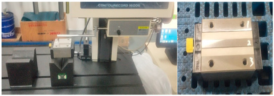
Figure 2.
Experiment setup.

Table 1.
Details of equivalent specimen.
Table 2.
Contact stiffness and material parameters of the fixed joints.
The fractal dimension D and fractal roughness parameter G were obtained from these experiment results.
4. Results and Discuss
The surface profile of each sample was measured by using the surface profilometer (CONTOURECORD 1600G-24 from TOKYO SEIMITSU, with a resolution of 0.1 μ m/5 mm). The sampling length was set to 20 mm and the sampling interval was 1 μ m. The surface of each sample was measured three times in different areas, resulting in different surface contours. After obtaining the contour height value, the first point of each contour was set to 0 and modified through fitting to correct shape errors in several surface contours caused by differences in sample stiffness. The local surface contours of the six specimens are shown in Figure 3a. Specimen 1 represents grinding Ra 0.8. (b) is specimen 2, representing milling Ra 1.6. (c) is specimen 3, representing milling Ra 3.2. (d) is specimen 4, representing grinding Ra 0.8 and scraping. (e) is specimen 5, representing milling Ra 1.6 and scraping. (f) is specimen 6, representing milling Ra 3.2 and scraping.
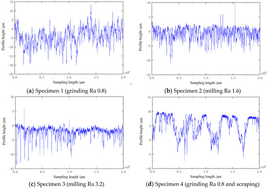
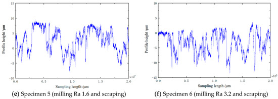
Figure 3.
Partial surface profile of each specimen.
The fractal dimension D and fractal roughness parameter G were obtained from the profile experiments. Based on Equations (20) and Equation (25), the NCS Kn and friction force are functions of the fractal dimension D and fractal roughness parameter G. Then, the NCS Kn and friction force are obtained in Figure 4a, representing the NCS and friction force for D = 1.25, G = 5.32 × 10⁻¹². (b) represents the NCS and friction force for D = 1.28, G = 1.34 × 10⁻¹¹. (c) represents the NCS and friction force for D = 1.32, G = 4.23 × 10⁻¹¹. (d) represents the NCS and friction force for D = 1.35, G = 9.23 × 10⁻¹¹. (e) represents the NCS and friction force for D = 1.38, G = 2.16 × 10⁻¹⁰. (f) represents the NCS and friction force for D = 1.42, G = 6.73 × 10⁻¹⁰.
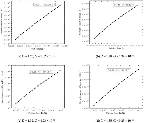
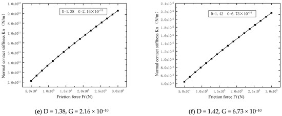
Figure 4.
The curve of NCS Kn and friction force .
From the curves of the NCS Kn and friction force , it is shown that with the increasing of fractal dimension D and fractal roughness parameter G, the NCS Kn is improved. From the curves in Figure 5, the friction coefficient is changed from 0.2, 0.4, 0.6 to 0.8; (a) represents the NCS for D = 1.28, G = 1.34 × 10⁻¹¹ (the maximum value of NCS is about 5 × 10¹¹), (b) represents the NCS for D = 1.32, G = 4.23 × 10⁻¹¹ (the maximum value of NCS is about 8 × 10¹¹), (c) represents the NCS for D = 1.38, G = 2.16 × 10⁻¹⁰ (the maximum value of NCS is about 1 × 10¹²), and (d) represents the NCS for D = 1.42, G = 6.73 × 10⁻¹⁰ (the maximum value of NCS is about 2.5 × 10¹²). Hence, for a certain fractal dimension D and fractal roughness parameter G, with the increasing of the friction coefficient, it is shown that the NCS Kn is improved in Figure 5.
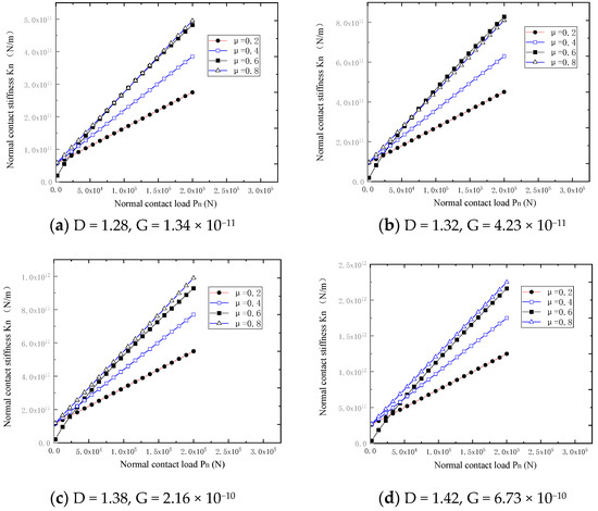
Figure 5.
The curve of NCS Kn with different friction coefficients.
5. Conclusions
In conclusion, the NCS calculation model based on fractal parameters considering the elastic–plastic deformation of the asperity and domain extension factor of joints is set up in this paper. Based on this model, the influence of the fractal parameters and the friction coefficient on the NCS of the joints is discussed. The deformation relationship of the asperity in different stages is established based on Hertz’s contact theory, elastic–plastic contact theory, and plastic contact theory. The investigation of asperity contact loads, NCS, contact areas, and the surface fractal parameters are deduced. The NCS of joints of CNC machine tools is studied by theoretical and experimental techniques. The results and conclusions are as follows:
(1) The elastic–plastic deformation mechanism of asperity presents an obvious influence on the normal contact stiffness of the joints. The NCS based on the calculation method considering the elastic–plastic deformation of the asperity is much higher in precision than the methods considering only elastic or plastic deformation separately. Therefore, for applications where high precision is required, such as in engineering design, material characterization, or tribology studies, the elastic–plastic deformation method is preferred. It provides a more comprehensive understanding of how materials behave under contact loading conditions and can lead to better predictions of NCS of CNC machine tools.
(2) The relationships between the normal contact stress (NCS), fractal dimension D, fractal roughness parameter G, and the friction coefficient μ are discussed. As the fractal dimension D and fractal roughness parameter G increase, the normal stress on each asperity increases, leading to an increase in NCS. For a given fractal dimension D and fractal roughness parameter G, an increase in the friction coefficient μ could indicate a higher level of interaction between the asperities of the two surfaces. This could be due to an increase in the real area of contact or an increase in the adhesive forces between the surfaces. Both of these factors can contribute to an increase in NCS.
(3) The observations this paper described suggest that in the CNC machine tools system, higher D and G and higher friction coefficients lead to higher normal contact stresses (NCSs). It is important to note that these relationships are not universal and can be influenced by various factors, including the material properties, the scale of observation, and the specific conditions of the contact (e.g., load, velocity, environment). The exact behavior of NCS with respect to these parameters would need to be further determined through much more experimental data and detailed numerical simulations in future studies.
Author Contributions
Methodology and Review & Editing, L.X.; Investigation and Original Draft Preparation, Y.T.; Software and Original Draft Preparation , X.L. All authors have read and agreed to the published version of the manuscript.
Funding
This work was supported by the National Natural Science Foundation of China (Grant, No. 51305069) and Research and Application of Reliability and Consistency Improvement Technology for CNC Machine Tools (Grant, No. 2022JH1/10400027).
Data Availability Statement
Data is unavailable due to privacy.
Conflicts of Interest
The authors declare no conflict of interest.
Nomenclature
| CNC | computer numerical control |
| NCS | normal contact stiffness |
| G-W | Greenwood and Williamson |
| M-B | Majumdar and Bhushan |
| D | fractal dimension |
| G | fractal roughness parameter |
| ae | contact area |
| ac | elastic critical contact area |
| aep | plastic critical contact area |
| Fe | contact force of the asperity |
| R | radius of the asperity |
| δ | elastic deformation of the asperity |
| δc | critical deformation |
| equivalent Young’s module | |
| E | Young’s module |
| v | Poisson’s ratio |
| K | coefficient of hardness |
| H | hardness |
| γ | scaling parameter of the spectral density |
| φn | random phase |
| normal contact load of rough interfaces | |
| friction force | |
| friction coefficient | |
| τ | interval in the sampling area |
| z(x) | height function of the surface profile |
| ⟨⟩ | statistical average of the surface height |
| C | sampling coefficient |
| ψ | domain extension factor |
References
- Qu, C.; Wu, L.; Ma, J. A fractal model of normal dynamic parameters for fixed oily porous media joint interface in machine tools. Int. J. Adv. Manuf. Technol. 2013, 68, 2159–2167. [Google Scholar] [CrossRef]
- Levina, Z.M. RESEARCH ON THE STATIC STIFFNESS OF JOINTS IN MACHINE TOOLS. In Advances in Machine Tool Design and Research 1967, Proceedings of the 8th International M.T.D.R. Conference (Incorporating the 2nd International CIRP Production Engineering Research Conference), University of Manchester Institute of Science and Technology, Manchester, UK, 11–15 September 1967; Pergamon Press: Oxford, UK, 1968. [Google Scholar]
- Jackson, R.L.; Green, I. On the Modeling of Elastic Contact between Rough Surfaces. Tribol. Trans. 2011, 54, 300–314. [Google Scholar] [CrossRef]
- Greenwood, J.; Williamson, J. Contact of Nominally Flat Surfaces. Proc. R. Soc. Lond. Ser. A Math. Phys. Sci. 1966, 295, 300–319. [Google Scholar]
- Li, L.; Wang, J.; Pei, X.; Chu, W.; Cai, A. A modified elastic contact stiffness model considering the deformation of bulk substrate. J. Mech. Sci. Technol. 2020, 34, 777–790. [Google Scholar] [CrossRef]
- Majumdar, A.; Bhushan, B. Fractal Model of Elastic-Plastic Contact Between Rough Surfaces. J. Tribol. Trans. Asme. 1991, 113, 1–11. [Google Scholar] [CrossRef]
- Jiang, S.Y.; Zheng, Y.J.; Zhu, H. A contact stiffness model of machined plane joint based on fractal theory. J. Tribol. Trans. ASME 2010, 132, 1–7. [Google Scholar] [CrossRef]
- Zhang, X.L.; Chen, Y.H.; Wen, S.H.; Lan, G.S.; Ding, H.Q.; Wang, N.S.; Zhang, Z.Y. The Model of Normal Contact Stiffness of Joint Interfaces Incorporating Elastoplastic Deformation Mechanism. J. Vib. Eng. 2015, 1, 91–99. [Google Scholar]
- Wang, R.; Zhu, L.; Zhu, C. Research on fractal model of normal contact stiffness for mechanical joint considering asperity interaction. Int. J. Mech. Sci. 2017, 134, 357–369. [Google Scholar] [CrossRef]
- Chen, Q.; Xu, F.; Liu, P.; Fan, H. Research on fractal model of normal contact stiffness between two spheroidal joint surfaces considering friction factor. Tribol. Int. 2016, 97, 253–264. [Google Scholar] [CrossRef]
- Chang, Y.; Ding, J.; He, Z.; Shehzad, A.; Ding, Y.; Lu, H.; Zhuang, H.; Chen, P.; Zhang, Y.; Zhang, X.; et al. Effect of joint interfacial contact stiffness on structural dynamics of ultra-precision machine tool. Int. J. Mach. Tools Manuf. Des. Res. Appl. 2020, 158, 103609. [Google Scholar] [CrossRef]
- Tian, H.; Li, B.; Liu, H.; Mao, K.; Peng, F.; Huang, X. A new method of virtual material hypothesis-based dynamic modeling on fixed joint interface in machine tools. Int. J. Mach. Tools Manuf. 2011, 51, 239–249. [Google Scholar] [CrossRef]
- Zhang, X.; Fan, S.; Wen, S.; Wang, Y.; Lan, G. Modeling method of fixed joint interfaces based on equivalent transversely isotropic virtual material. J. Mech. Eng. 2017, 53, 141–147. [Google Scholar] [CrossRef]
- Varga, J.; Ižol, P.; Vrabeľ, M.; Kaščák, Ľ.; Drbúl, M.; Brindza, J. Surface Quality Evaluation in the Milling Process Using a Ball Nose End Mill. Appl. Sci. 2023, 13, 10328. [Google Scholar] [CrossRef]
- Grešová, Z.; Ižol, P.; Vrabeľ, M.; Kaščák, Ľ.; Brindza, J.; Demko, M. Influence of ball-end milling strategy on the accuracy and roughness of free form surfaces. Appl. Sci. 2022, 12, 4421. [Google Scholar] [CrossRef]
- Stoica, A.; Stan, G. Influence of the ball screw stiffness on the positioning accuracy of the CNC machine tools. IOP Conf. Ser. Mater. Sci. Eng. 2021, 1182, 012076. [Google Scholar] [CrossRef]
- Chen, G.; Zheng, Q. A rapid identification method for stiffness among ends of multi-axis CNC machine tools. Zhongguo Jixie Gongcheng 2017, 28, 322–326. [Google Scholar]
- Guzeev, V.I.; Nurkenov, A.K. Researching the CNC-Machine Stiffness Impact on the Grinding Cycle Design. Procedia Eng. 2016, 150, 815–820. [Google Scholar] [CrossRef][Green Version]
- Bandara, S.; Jin, Y.; Van, M.; Sun, D.; Fu, R.; Curley, P.; Higgins, C. Stiffness Measurement of Parallel Kinematic Machines Considering Gravity Effect. Adv. Transdiscipl. Eng. 2022, 25, 155–160. [Google Scholar]
- Kamboj, G.; Gaff, M.; Smardzewski, J.; Haviarová, E.; Hui, D.; Rezaei, F.; Sethy, A.K. Effect of cellulose nanofiber and cellulose nanocrystals reinforcement on the strength and stiffness of PVAc bonded joints. Compos. Struct. 2022, 295, 115821. [Google Scholar] [CrossRef]
- Guzeev, V.I.; Nurkenov, A.K.; Ignatova, A.V. Research stiffness of CNC plunge grinding machine units. Russ. Eng. Res. 2015, 35, 69–72. [Google Scholar] [CrossRef]
- Yang, X.; Zhang, M.; Cheng, R.; Cheng, R.; Zhu, Y. Identification and compensation of stiffness and damping between short and long stroke in wafer stage. J. Phys. Conf. Ser. 2021, 1986, 012056. [Google Scholar] [CrossRef]
- Sarhan, A.A.D.; Matsubara, A. Investigation about the characterization of machine tool spindle stiffness for intelligent CNC end milling. Robot. Comput.-Integr. Manuf. 2015, 34, 133–139. [Google Scholar] [CrossRef]
- Barkane, A.; Platnieks, O.; Grase, L.; Gaidukovs, S. Simultaneous wettability and stiffness control of UV-curing vegetable oil resin composites by lignocellulosic components. Polymer 2022, 255, 125154. [Google Scholar] [CrossRef]
- Liu, Z.; Jiang, K.; Zhang, C.; Zhao, Y.; Tian, Y. A stiffness model of a joint surface with inclination based on fractal theory. Precis. Eng. 2020, 62, 47–61. [Google Scholar] [CrossRef]
- Greenwood, J.A.; Tripp, J.H. The Contact of Two Nominally Flat Rough Surfaces. Proc. Inst. Mech. Eng. 1970, 185, 625–634. [Google Scholar] [CrossRef]
- Chang, W.R.; Etsion, I.; Bogy, D.B. An Elastic-Plastic Model for the Contact of Rough Surfaces. J. Tribol. 1987, 109, 257–263. [Google Scholar] [CrossRef]
- Kligerman, Y.; Etsion, I.; Kadin, Y. Unloading of an Elastic-Plastic Loaded Spherical Contact. In Proceedings of the ASME/STLE International Joint Tribology Conference. American Society of Mechanical Engineers, Long Beach, CA, USA, 24–27 October 2004. [Google Scholar]
- Bhushan, B.; Majumdar, A. Discussion: “A Fractal Theory of the Interfacial Temperature Distribution in the Slow Sliding Regime: Part I—Elastic Contact and Heat Transfer Analysis” (Wang, S. and Komvopoulos, K. 1994, ASME J. Tribol. 116, pp. 812–822. J. Tribol. 1994, 116, 822. [Google Scholar] [CrossRef]
- Fang, B. Theoretical Modeling and Experimental Study of Precision CNC Machine Tools and Its Typical Interface; Jilin University: Changchun, China, 2013. [Google Scholar]


Disclaimer/Publisher’s Note: The statements, opinions and data contained in all publications are solely those of the individual author(s) and contributor(s) and not of MDPI and/or the editor(s). MDPI and/or the editor(s) disclaim responsibility for any injury to people or property resulting from any ideas, methods, instructions or products referred to in the content. |
© 2024 by the authors. Licensee MDPI, Basel, Switzerland. This article is an open access article distributed under the terms and conditions of the Creative Commons Attribution (CC BY) license (https://creativecommons.org/licenses/by/4.0/).