Article

An Experimental Investigation of the Electrical Tribological Characteristics of a Copper–Silver Alloy Contact Wire/Novel Pure Carbon Slider

Standards & Metrology Research Institute, China Academy of Railway Sciences Corporation Limited, Beijing 100015, China
*
Author to whom correspondence should be addressed.
Lubricants 2025, 13(2), 87; https://doi.org/10.3390/lubricants13020087
Submission received: 20 January 2025 / Revised: 11 February 2025 / Accepted: 14 February 2025 / Published: 16 February 2025
(This article belongs to the Special Issue Advances in Dry and Lubricated Electrical Contacts)

Abstract

:
The sliding electric contact that is established between the catenary wire and pantograph slider serves as the primary mechanism through which contemporary high-speed railway trains obtain their driving energy. The wear resistance of both the sliders and contact wires significantly influences their service life. This paper reports an experimental investigation into the electrical tribological characteristics of a copper–silver alloy contact wire in conjunction with a novel pure carbon slider, conducted under AC 300–500 A at sliding velocities ranging from 150 to 250 km/h. The experimental tests reveal that the coefficient of friction changes from 0.20 to 0.28, and the wear rate of the sliders varies from 0.0028 to 0.0147 g/km. The observed wear mechanisms for the slider encompass arc ablation, abrasive wear, delamination wear, and adhesive wear.

1. Introduction

In recent years, China’s railway industry has achieved rapid development. The cumulative length of China’s railway main-lines is projected to reach approximately 160,000 km, including 46,000 km that are dedicated to high-speed railway lines, by the end of 2024. As of 2024, over 100,000 km of China’s railway main-lines have been electrified, representing 62.5% of the total railway main-line mileage. The traction of electrified trains relies entirely on the electrical sliding that is established between the overhead wires and sliders. This friction couple, which can be characterized as either a line contact or small-rectangular area contact after wear, must transmit an AC of 300–500 A at a maximum relative slip velocity of 250 km/h, thus subjecting the pantograph–catenary system to extremely demanding operational conditions. The longevity of contact wires and sliders primarily hinges on their wear resistance, making the enhancement of their wear life a critical focus in the ongoing research and development of electrified railways.
It is well known that to enhance the operational lifespan of sliders and contact wires, one needs to comprehend the wear mechanisms of sliders and overhead wires. The current-carrying tribological characteristics of sliders that are in contact with overhead wires are influenced by a multitude of factors. Therefore, the evolution of the electric sliding tribological characteristics is more complicated than that of those without an electric current. A significant amount of research has been conducted to investigate the current-carrying tribological characteristics of sliders that are in contact with wires [1,2,3,4,5]. Gao et al. [6] developed a novel metal-impregnated carbon slider with tungsten disulfide. Their current-carrying friction test results showed that with the increase in electric current, the slider progressively transitioned from abrasive wear and fatigue wear to adhesive wear. Liu et al. [7] reported that the wear mechanisms for carbon skateboards/conductive rail friction couples were primarily adhesive wear in the presence of gaps, whereas those of friction couples were mainly abrasive wear in the absence of gaps. Chen et al. [8] concluded that the wear mechanisms were the combined effects of adhesive wear, oxidation wear, and fatigue wear for an elastic roll ring rubbing against another elastic roll ring. Wu et al. [9] reported that when the humidity increased from 0% to 80%, a tribofilm was formed, and abrasive wear was suppressed. Yang et al. [10] thought that the increase in arc discharge significantly altered the wear mechanism of the slider, and that the intensity of the arc discharge directly influenced the formation of delamination wear. Hu et al. [11] concluded that when increasing the energy of the arc discharge, the degree of arc ablation of the sliders intensified. The arc ablation served as the primary contributor to both the rise in temperature and significant wear experienced by the slider. Mei [12] reported that the voltage between the overhead wire and slider exerted a significant influence on the wear characteristics of sliders rubbing against the contact line. Ren and Chen [13] concluded that the dominant wear mechanisms of the contact line included abrasive wear and arc ablation. Bucca and Collina [14] proposed a procedure combining a wear model for the interaction between sliders and overhead lines, incorporating a simulation of the dynamic interplay between sliders and contact lines. Derosa et al. [15] studied the effects of the lateral speed of sliders at the contact point on the slider wear during railway operations and concluded that the lateral speed did not influence the electrical and mechanical wear related to the arcs; but it did impact the electrical component related to the Joule effect. Kato and Kubo [16,17] proposed that the slider wear was strongly correlated with the arc energy. Chen et al. [18] also reached the same conclusion as Kubo and Kato. The current-carrying tribological characteristics of slider–overhead wire systems are particularly intricate, encompassing not only conventional mechanical and thermal wear, but also arc erosion and severe thermal damage induced by electrical currents [19,20,21,22,23,24,25].
In China’s railways, pure carbon sliders account for almost half of all types of sliders. The classification of train speed grades in China’s railway main-lines can be broadly categorized as follows: Conventional-speed trains refer to those whose operational speeds range from 30 to 120 km/h. Medium-speed trains refer to those whose operational speeds are in the range of 120–160 km/h. Quasi-high-speed or fast trains refer to those whose operational speeds range from 160 to 250 km/h. High-speed trains refer to those whose operational speeds range from 250 to 400 km/h. Currently, the contact lines that are utilized in China’s electrified railway lines mainly encompass copper–magnesium alloy, copper–tin alloy, and copper–silver alloy (Cu-Ag) contact lines. Notably, Cu-Ag contact lines are suitable for electrified catenary systems in which the train speeds range from 120 to 250 km/h. Types of pantograph sliders that are employed in China include sintered alloy sliders, pure carbon sliders, and metal-impregnated carbon sliders. Specifically, vehicle types such as the CRH1A-200, CRH1A-250, CRH1B, CRH2A, CRH2C-1, CRH2C-2, CRH2E, CRH3A, CRH380A, CRH380AL, CRH6A, and CR300AF predominantly utilize pure carbon sliders, whereas vehicle types like the CRH380B, CRH380BL, CRH380BG, CRH380D, CR400AF, CR400BF, CR300BF, and CRH5 employ metal-impregnated carbon sliders.
The objective of this study is to systematically investigate the electrical sliding tribological performance of a novel pure carbon slider in contact with a Cu-Ag line and to elucidate the mechanisms influencing the wear of the pantograph–catenary friction couples. Our work aims to provide valuable insights for optimizing the material compatibility, minimizing material damage, and enhancing the service life of pantograph–catenary systems that are used in China’s quasi-high-speed or fast trains operating at speeds of 160–250 km/h.

2. Experimental Apparatus and Test Parameters

2.1. Experimental Apparatus

2.1.1. Experimental Machine

The experimental research presented in this paper was conducted using a current-carrying tribological experimental machine. This machine was a ring-block configuration, mainly comprising a foundation base, a framework, a variable-frequency drive, a rotational disk with an overhead wire, a slider carrier with a slider, and a crank linkage mechanism for producing up-and-down staggering motion, as illustrated in Figure 1. The overhead line was mounted on a rotational disk with a 1100 mm diameter, actuated by a changeable-frequency drive with a rated power of 58 kW to mimic 25 to 300 km/h relative sliding between the contact wire and slider. The variable-frequency motor actuated a crank linkage mechanism to emulate the staggering motion of a slider in relation to the contact line. The staggering motion had an amplitude of ±55 mm within a frequency range of 0.5 Hz. The pulley and dead weight system simulated the normal force between the overhead wire and slider.

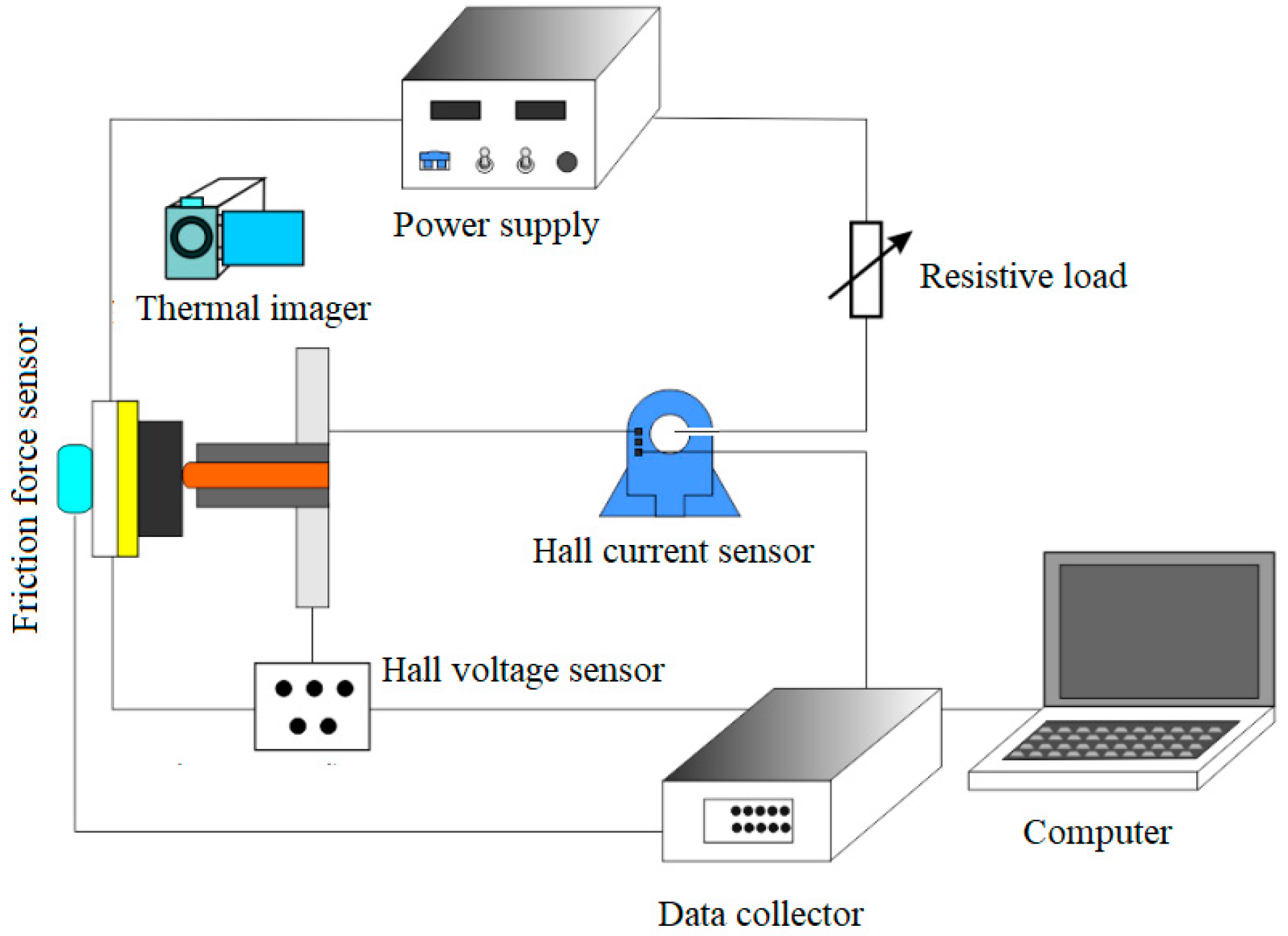
2.1.2. Data Measurement System and Passing Current Circuit

Figure 2 illustrates the data measurement system and passing current circuit of the overhead line and slider. The passing current circuit was mainly composed of a resistive load and an alternating current power supply. The data measurement system mainly consisted of a Hall voltage and current sensors, a friction force sensor, a thermal imager, a data collector, and a computer. The Hall voltage (current) sensing device was used to detect the arc voltage (current) signal. The data collector was used to measure the arc current, voltage, and friction force signals. Given the minimal wear of the overhead line and the challenges associated with its assembly and disassembly, the wear of the overhead wire was disregarded in the test. The mass loss due to wear of the slider was determined by measuring the difference in mass before and after testing, utilizing an electronic balance that has a precision of 0.1 mg. During tests, the temperature of the overhead wire and the slider was monitored utilizing an infrared thermal imager. The imager could accurately measure the temperature of objects up to 5 m away from the target, with a thermal sensitivity of 0.1 °C and an accuracy of ±2%. Figure 3 illustrates a measurement of a friction pair temperature.

2.2. Specimen

2.2.1. Physical Parameters and Composition of the Cu-Ag Line

The overhead line used in the present test was a CTA-120 Cu-Ag line with a cross-sectional area of 120 mm2. This line was new and had not been previously used. The Cu-Ag line had an electrical conductivity of 96.5% IACS, a tensile strength of 353 MPa, and an elongation rate of 3.0%. The Cu-Ag line had a hardness of HRC 82. Table 1 provides the chemical composition of the Cu-Ag line.

2.2.2. Physical Parameters and Components of the Pure Carbon Slider

The test utilized a new type of pure carbon slider. Table 2 provides the slider’s physical parameters. The slider’s chemical composition was determined by a specialized organization. The specific values are provided in Table 3.

2.3. Specimen Preparation Method

The Cu-Ag line was embedded in the card slot around the rotational disk of the experimental machine. The friction surface of the Cu-Ag line was cut using a lathe cutting system after installation. The radial run-out of the contact wire during one rotation was about 0.10 mm.
The slider sample was sourced from the slider material used in railways, with dimensions of 120 mm × 34 mm × 25 mm.

2.4. Arc Energy Calculation Method

The arc current and voltage signals were sampled at 1000 Hz. The arc energy was calculated as follows:
E a r c = U a r c I a r c d t S
where E a r c is the arc discharge energy (J/km), U a r c is the measured voltage of the slider relative to the overhead wire (V), and I a r c is the arc current passing from the slider to the overhead wire (A). t is the test time (s), and S is the sliding distance of the slider relative to the contact wire during the test duration (km).

2.5. Test Parameters

Considering the specific conditions of slider–overhead line systems in China’s railway main-lines, the following test parameters were adopted: AC currents of 300, 400, and 500 A; contact normal forces of 50, 70, and 90 N; slip speeds of 150, 200, and 250 km/h; and a sliding distance of 250 km.

2.6. Test Procedures

Prior to every test, the overhead line surface was burnished with 800–1000 grit sandpaper to remove any residual surface oxide film and material transfer layer from the previous test, ensuring that the surface roughness reached approximately Ra 6.4 μm. At the beginning of each test, under the specified normal force, the contact wire was slid on the slider for 5 min at 25 km/h in case of no current to ensure good contact between the overhead line and slider. Then, the prescribed current was imposed. Every test was conducted in triplicate under identical conditions. The test result was the mean of these three trials.

3. Test Results

3.1. Change in Sliding Coefficient of Friction with Sliding Speed

Tribological properties primarily include the wear rate and coefficient of friction. Figure 4 illustrates the change in the coefficient of friction with respect to the sliding speed. It can be observed that the coefficient of friction reduced slightly with current. This was because an increase in current led to greater arc ablation of the slider, resulting in more carbon particles being transferred to the contact wire. These carbon particles had a lubricating effect, which contributed to a slight decrease in the sliding coefficient of friction. Within the test parameter range, the sliding coefficient of friction between the overhead line and slider varied from 0.20 to 0.28.

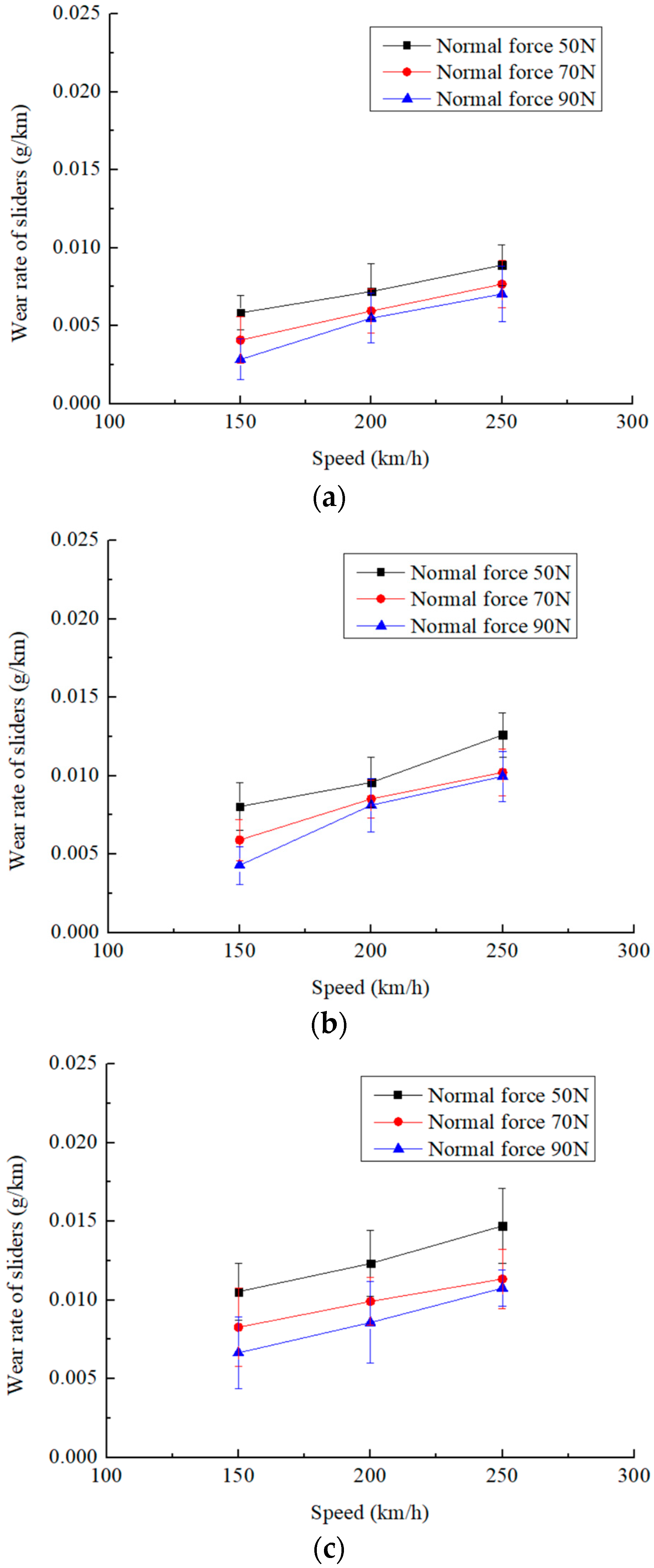
3.2. Changes in Wear Rate of Sliders with Slip Speed

Figure 5 illustrates the changes in the wear rate of the slider relative to the slip speed. It might be observed that, when other parameters remained unchanged, the slider wear rate increased with the slip speed. For example, when the current was 500 A and the normal force was 50 N, the wear rate of the slider was 0.0105 g/km at 150 km/h. At 250 km/h, the wear rate increased to 0.0147 g/km. The wear rate at 250 km/h was 1.4 times that at 150 km/h, indicating that the sliding speed obviously influenced the abrasion of the slider. The general trend was that the slider wear rate increased with the slip speed. In Figure 5a–c, the wear rate of the slider changed from 0.0028 g/km to 0.0147 g/km.

3.3. Variations in Wear Rate of Sliders with Electric Current

In Figure 6, the impact of the electric current on the wear rate of sliders is depicted. It might be observed that the wear rate of the pantograph sliders increased with the electric current. The wear rate of the slider was 0.0089 g/km at an AC current of 300 A under a sliding speed of 250 km/h. The slider wear rate increased to 0.0147 g/km at an AC current of 500 A. The wear rate at 500 A was 1.65 times that at 300 A, indicating that the current obviously influenced the abrasion of the sliders.

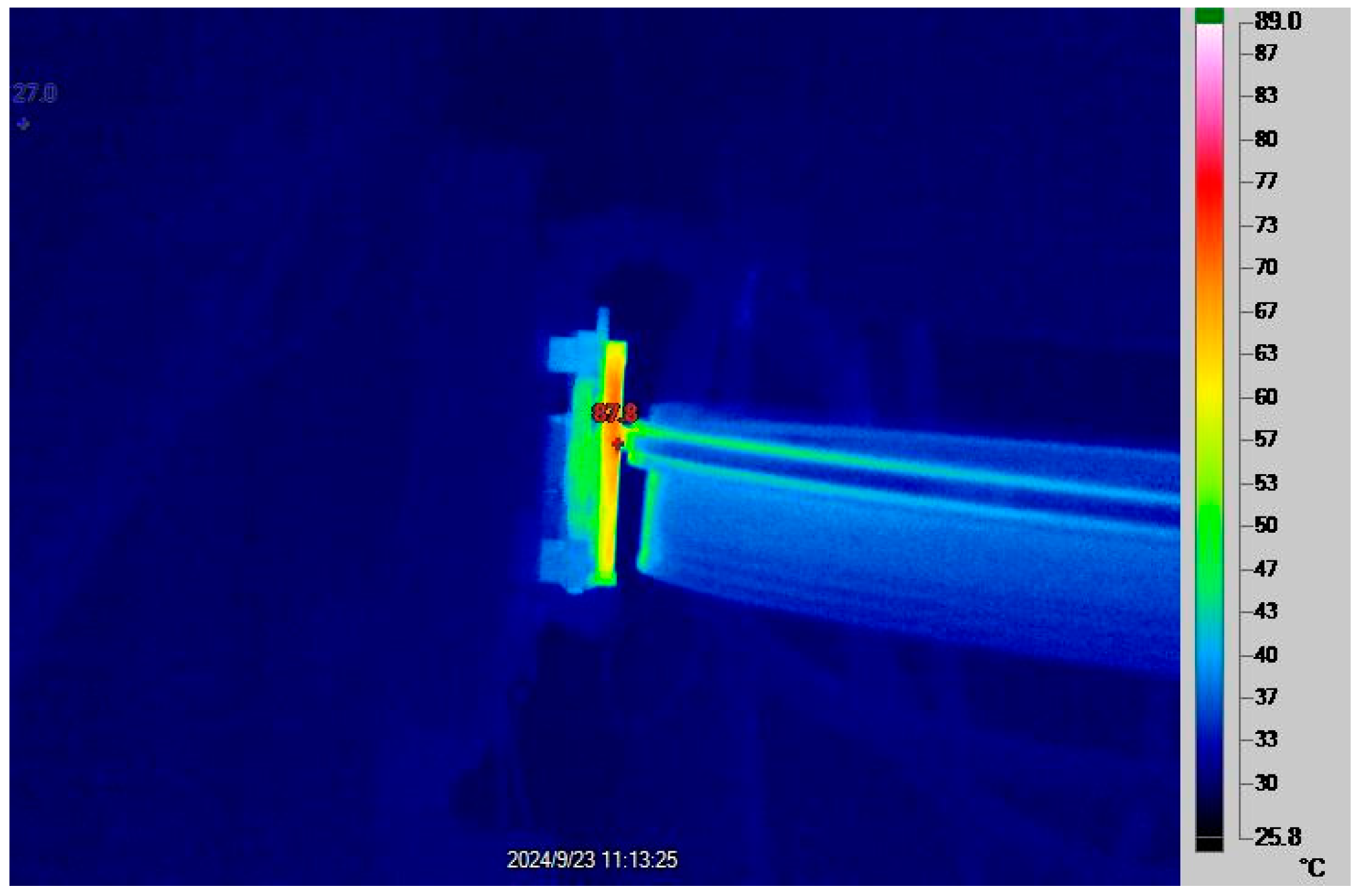
3.4. Changes in Temperature Rise of Sliders as a Function of Electric Current

High temperatures could cause the slider and overhead wire materials to soften and reduce the resistance of the materials to deformation and adhesion transfer, which induces serious wear of the materials. Figure 7 depicts the changes in the temperature rise of the sliders as a function of the electric current. From Figure 7, it can be observed that under the same sliding speed, the temperature rise of the sliders increased with the current. For instance, when the normal force equaled 50 N and the slip speed equaled 250 km/h, the slider temperature rise reached 163.4 °C at an electric current of 300 A. When the current was 500 A, the slider temperature rise reached 275.8 °C. As can be seen in Figure 7, when the sliding speed and current remained unchanged, the decrease in normal force led to an increase in the slider temperature rise. This was because a reduction in the normal force increased the likelihood of contact separation between the slider and overhead line, which could lead to increased arcing and subsequent ablation. This, in turn, led to a rise in the temperature of the sliders.

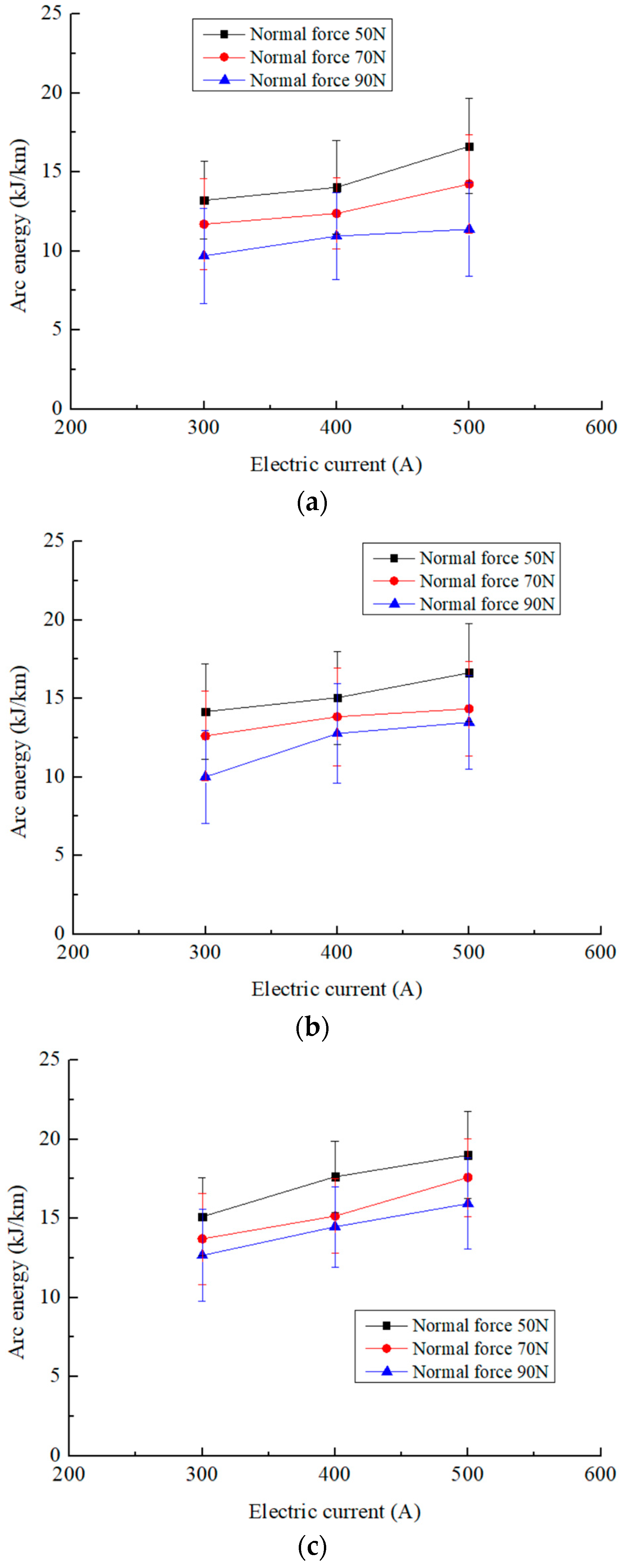
3.5. Changes in Arc Energy with Electric Current

According to scholars’ experimental studies, the arc is a critical factor causing severe wear of railway pantograph–catenary systems, and the intensity of arc ablation primarily depends on the arc energy [16,17,18]. Figure 8 illustrates the changes in arc energy as a function of the electric current. It can be observed that the arc energy increased with the increase in current under the same slip speed.

4. Discussion

4.1. Wear Mechanism of Sliders with Current

Figure 9 illustrates the SEM observation and EDS analysis of the slider scars. It can be seen that arc ablation, adhesion, delamination, and plowing wear are dominant wear mechanisms of the sliders in the presence of a current. Due to the staggering motion of the contact wire, the ablation region did not encompass the entire working surface of the slider. This phenomenon was consistent with intermittent arc discharge. In the ablation area, there were a large number of cracks. The formation of these cracks was related to arc ablation. The pure carbon slider materials were characterized by brittleness, and they were easy to crack under an external force or arc. Under the combined action of the alternating stress and friction, the crack friction zone of the slider produced delamination wear, which aggravated the material wear of the slider [10]. Since the hardness (HRC 82) of the Cu-Ag line was higher than the hardness (HRC 76) of the pure carbon slider, some debris from the Cu-Ag line might abrade the slider working surface, resulting in scratches.

4.2. Impact of Electric Current on the Wear Rate of Sliders

It was found that the wear rate of the sliders increased with the electric current, as shown in Figure 6. The current could produce ablation loss and thermal abrasion. The slider ablation loss was dominant in the total abrasion loss of the slider, including mechanical abrasion, thermal abrasion, and ablation loss. Figure 10 illustrates a comparative analysis of the slider wear in the presence and absence of a current. It was found that the slider wear rate in the presence of a current was about 6~7 times as high as that of the slider wear rate in the absence of a current. Figure 11 displays a comparative analysis of the slider temperature in the presence and absence of a current. It was found that the slider temperature rise in the presence of a current was about 4.6~8.8 times as high as that in the absence of a current. The thermal wear was mainly connected to adhesive wear. When the temperature of the slider was high, the slider material was softened. In this case, the adhesive wear of the slider became severe under the action of the same tangential friction force.

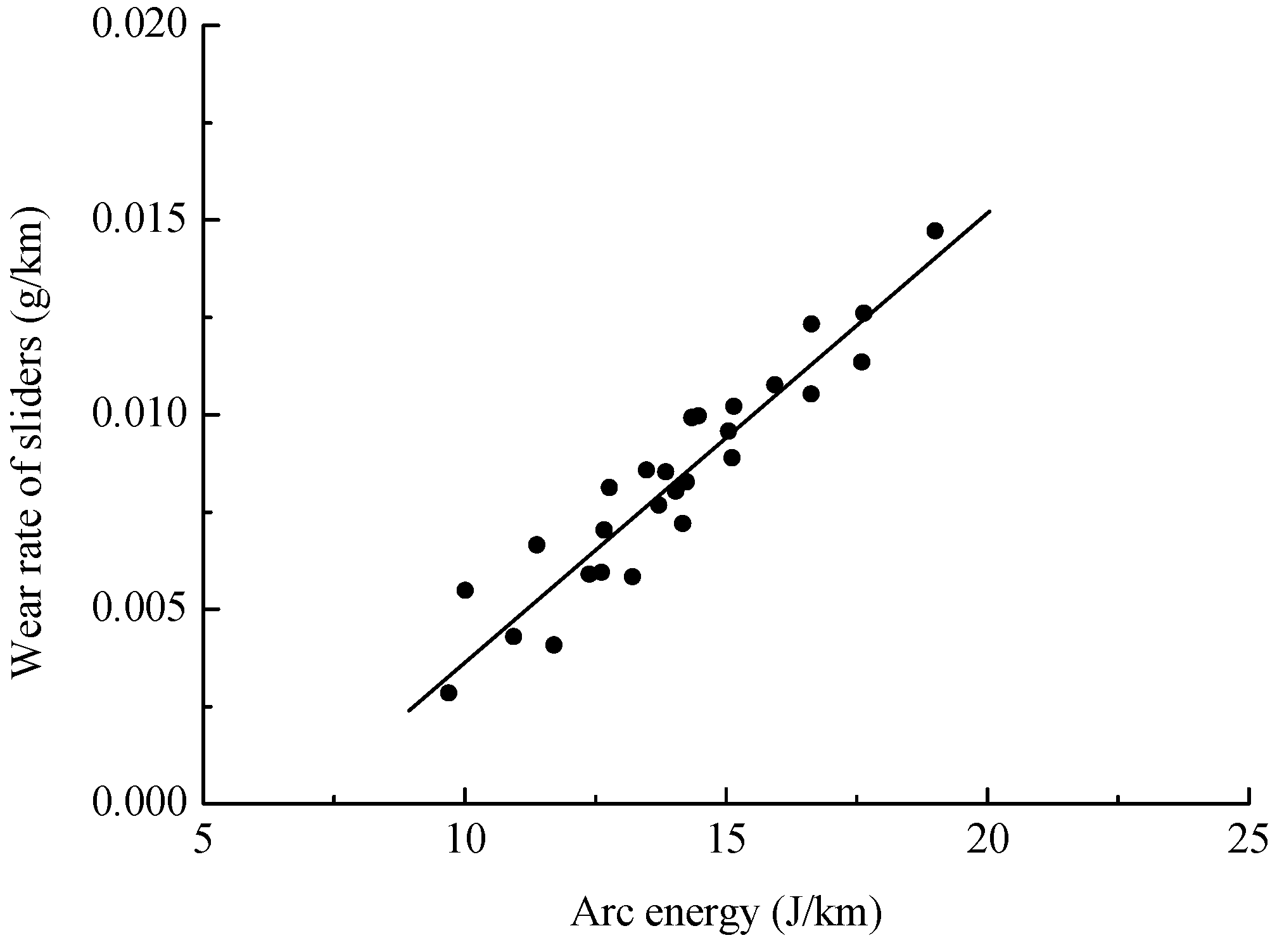
4.3. Effect of Arc Energy on the Slider Wear Rate

As can be seen from Figure 5 and Figure 6, the wear rate of the sliders decreased with normal force. By comparing Figure 6 with Figure 8, it can be observed that the change trend of the slider wear rate with the current resembled that of the arc energy with the current. These characteristics indicated that there was a significant correlation between the slider wear and arc ablation. Kubo and Kato [16,17] concluded the slider abrasion was proportional to the arc energy. Figure 12 presents a scatter diagram of all the arc energy values and the corresponding wear rates of sliders. From Figure 12, one could conclude that arc ablation was the dominant abrasion mechanism behind the slider wear. In Figure 12, the R2 value for the linear fit is about 0.99863.

5. Conclusions

Several experimental tests on the current-carrying tribological behavior of a new pure carbon slider sliding on a Cu-Ag line were performed in the paper. The main conclusions are as follows:
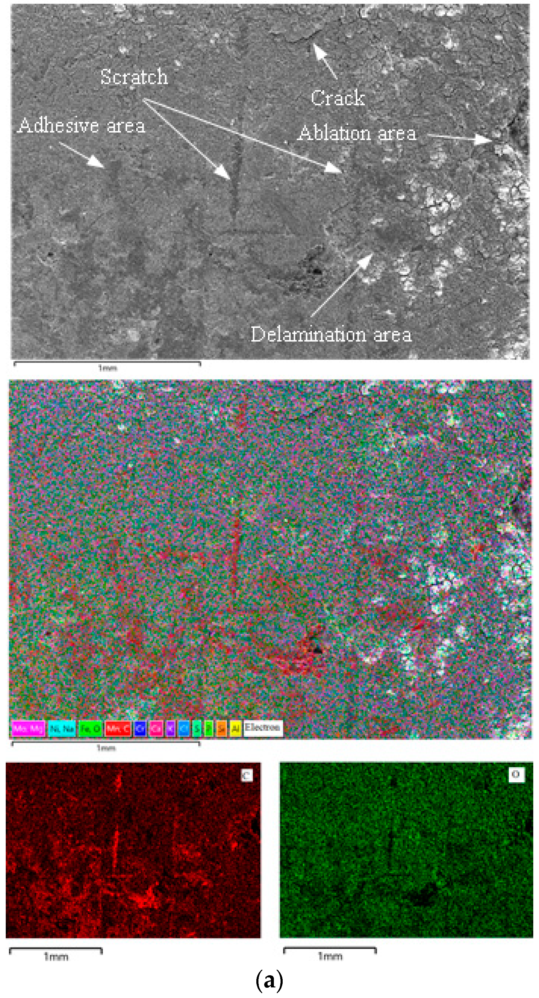
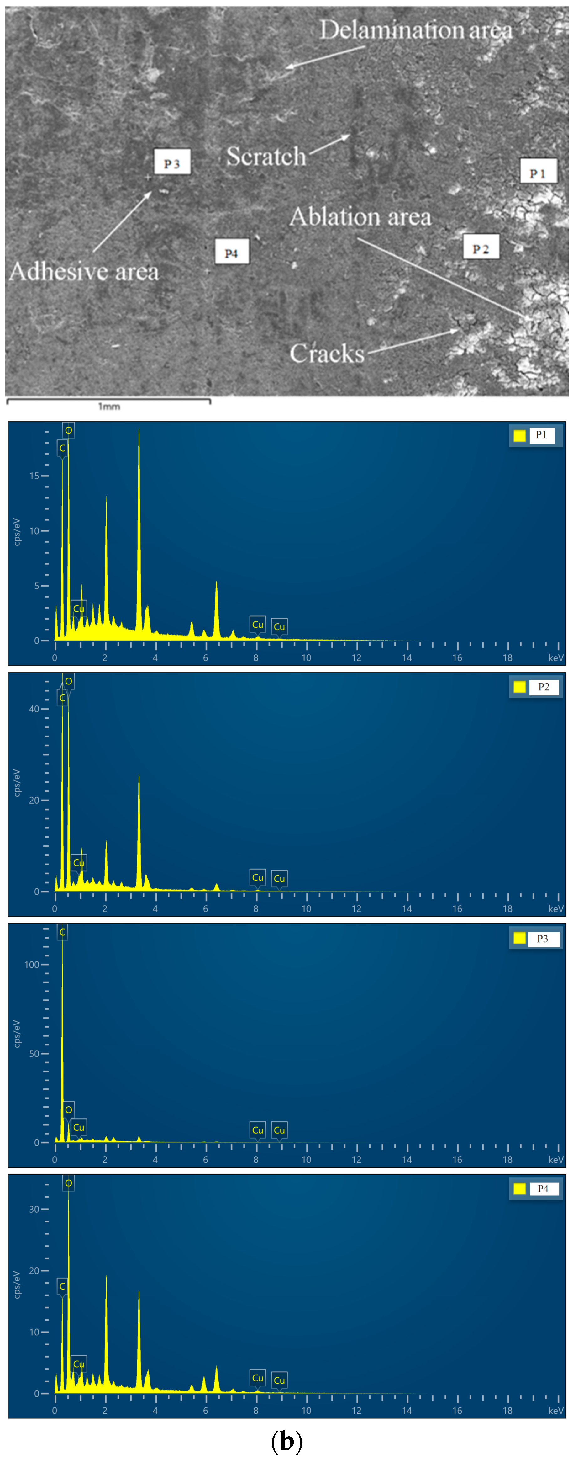
  • When the new pure carbon slider is sliding on a Cu-Ag line with a current, the abrasion mechanisms of sliders are mainly arc ablation, adhesive abrasion, abrasive abrasion, and delamination abrasion. Among these wear mechanisms, arc ablation stands out as the predominant wear mechanism affecting the sliders.
  • The coefficient of friction of the new pure carbon slider sliding on a Cu-Ag line in the presence of an electric current decreases with the sliding speed when other test parameters remain unchanged. Within the range of the test parameters, the coefficient of friction varies from 0.20 to 0.28.
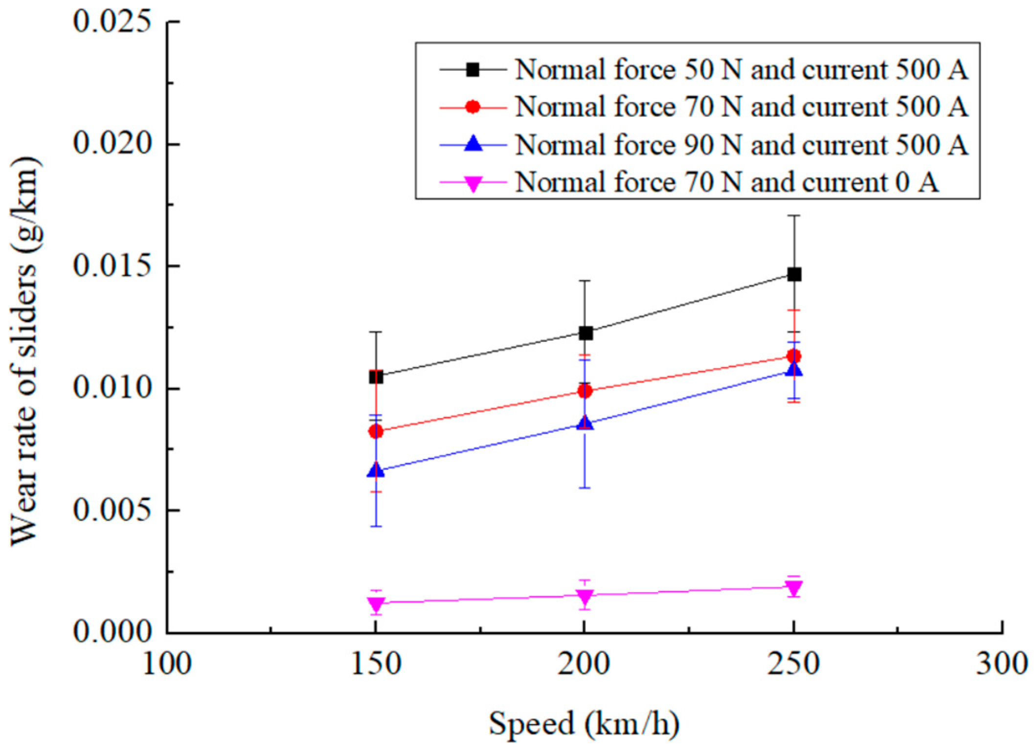
  • The wear rate of the pure carbon slider increases with the electric current when the other test parameters remain unchanged. Within the range of the test parameters, the slider wear rate varies from 0.0028 g/km to 0.0147 g/km.
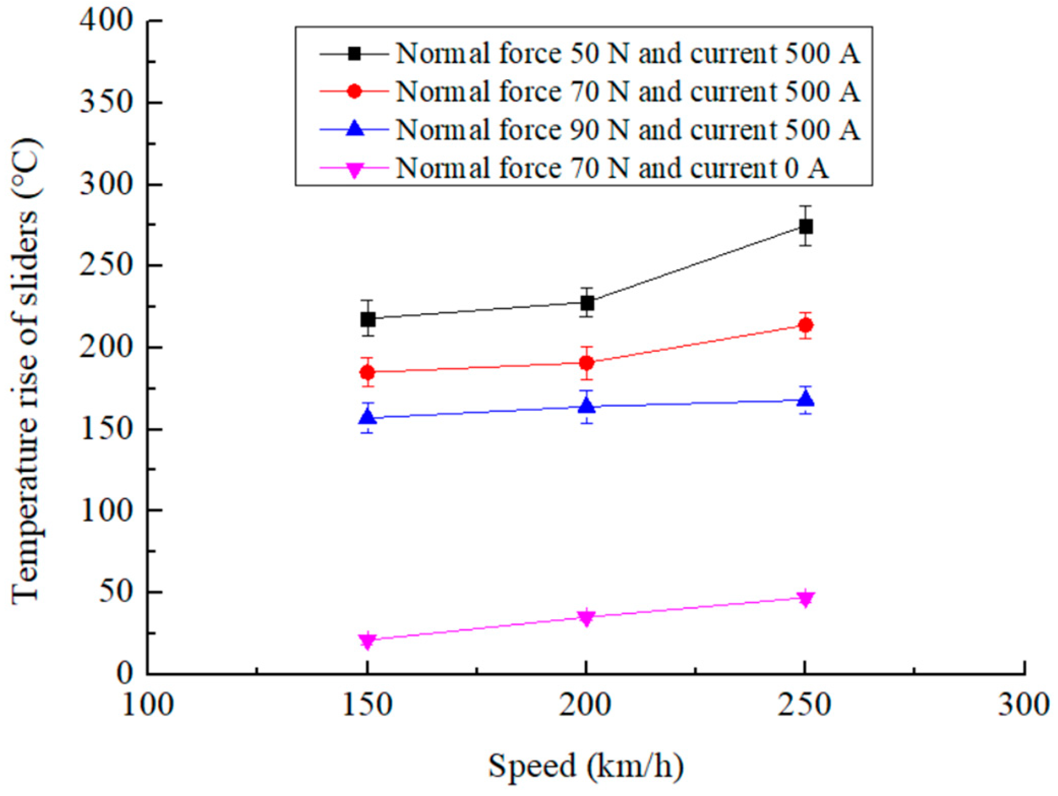
  • When the other test parameters remain unchanged, the temperature of the pure carbon slider increases with the electric current. Within the range of the test parameters, the temperature rise of the slider varies from 89.4 °C to 269.2 °C.
  • There is a significant correlation between the arc energy and slider wear. Suppressing the arc ablation can significantly decrease the wear of new pure carbon sliders sliding on a Cu-Ag line with an electric current.

Author Contributions

L.P.: Conceptualization, Methodology, Investigation, Data curation, Writing—original draft, and Funding acquisition. C.Y.: Conceptualization, Methodology, Writing—review and editing, and Funding acquisition. T.X.: Methodology, Investigation, and Writing—review and editing. Q.Y.: Methodology, Validation, and Data curation. All authors have read and agreed to the published version of the manuscript.

Funding

This research was funded by the Research Project of China Academy of Railway Sciences Corporation Limited (2024YJ281) and the Science and Technology Research Project of China Railway Co., Ltd. (J2023J010).

Data Availability Statement

The original contributions presented in this study are included in the article. Further inquiries can be directed to the corresponding author.

Conflicts of Interest

All authors were employed by China Academy of Railway Sciences Corporation Limited. All authors declare that the research was conducted in the absence of any commercial or financial relationships that could be construed as a potential conflict of interest.

References

  1. Chen, T.H.; Song, C.F.; Zhang, Y.Y.; Niu, K.; Liu, Z.L.; Wang, L.; Sun, C.; Li, M.J.; Zhang, Y.Z. Current-carrying contact character and wear behavior of an elastic ring at different rolling speeds. Eng. Fail. Anal. 2022, 131, 105825. [Google Scholar] [CrossRef]
  2. Mei, G.M. Tribological performance of rigid overhead lines against pantograph sliders under DC passage. Tribol. Int. 2020, 151, 106538. [Google Scholar] [CrossRef]
  3. Yang, H.J.; Chen, G.X.; Gao, G.Q.; Wu, G.N.; Zhang, W.H. Experimental research on the friction and wear properties of a contact strip of a pantograph–catenary system at the sliding speed of 350 km/h with electric current. Wear 2015, 332–333, 949–955. [Google Scholar] [CrossRef]
  4. Senouci, A.; Frene, J.; Zaidi, H. Wear mechanism in graphite-copper electrical sliding contact. Wear 1999, 225–229, 949–953. [Google Scholar] [CrossRef]
  5. Nagasawa, H.; Kato, K. Wear mechanism of copper alloy wire sliding against ironbase strip under electric current. Wear 1998, 216, 79–183. [Google Scholar] [CrossRef]
  6. Gao, M.-S.; Liu, X.-L.; Peng, T.; Xiao, Q.; Shen, M.-X.; Zhang, D.; Cao, H.-Y.; Wang, Z.; Yang, W.-B.; Chen, D.-Y. Study on the current-carrying friction and wear behaviors of a novel copper-impregnated carbon skateboard containing tungsten disulfide. Tribol. Int. 2025, 204, 110430. [Google Scholar] [CrossRef]
  7. Liu, X.-L.; Guan, X.; Zhong, Y.; Xiao, Q.; Cao, Y.; Zhang, W.-L.; Zhang, S.; Zheng, Y.-T.; Gao, M.-S.; Chen, D.-Y.; et al. Effect of different gaps in the conductor rail joints on the current-carrying wear performance of carbon skateboards/conductive rail contact. Wear 2024, 536–537, 205172. [Google Scholar] [CrossRef]
  8. Chen, T.; Song, C.; Liu, Z.; Wang, L.; Hou, X.; Lu, H.; Zhang, Y. Current-carrying tribological properties of an elastic roll ring under different currents. Wear 2023, 514–515, 204590. [Google Scholar] [CrossRef]
  9. Wu, R.; Song, C.; Wu, H.; Lv, B.; Zhang, Y.; Zhang, Y. Effect of relative humidity on the current-carrying tribological properties of Cu–C sliding contact pairs. Wear 2022, 492–493, 204219. [Google Scholar] [CrossRef]
  10. Yang, H.; Li, C.; Liu, Y.; Fu, L.; Jiang, G.; Cui, X.; Hu, B.; Wang, K. Study on the delamination wear and its influence on the conductivity of the carbon contact strip in pantograph-catenary system under high-speed current-carrying condition. Wear 2021, 477, 203823. [Google Scholar] [CrossRef]
  11. Hu, Y.; Huang, P.; Cheng, C.; Zhang, M.; Ma, R. Influence of arc discharge on the temperature and wear behaviors of the contact strip in pantograph-rigid catenary systems under AC conditions. Wear 2024, 546–547, 205368. [Google Scholar] [CrossRef]
  12. Mei, G.M.; Fu, W.M.; Chen, G.X.; Zhang, W.H. Effect of high-density current on the wear of carbon sliders against Cu–Ag wires. Wear 2020, 452–453, 203275. [Google Scholar] [CrossRef]
  13. Ren, W.; Chen, G. Experimental study on the wear mechanism of the contact line in rigid pantograph-catenary systems. Tribol. Int. 2023, 187, 108739. [Google Scholar] [CrossRef]
  14. Bucca, G.; Collina, A. A procedure for the wear prediction of collector strip and catenary wire in pantograph–catenary system. Wear 2009, 266, 46–59. [Google Scholar] [CrossRef]
  15. Derosa, S.; Navik, P.; Collina, A.; Bucca, G.; Rønnquist, A. Contact point lateral speed effects on contact strip wear in pantograph-catenary interaction for railway operations under 15 kV 16.67 Hz AC systems. Wear 2021, 486–487, 204103. [Google Scholar] [CrossRef]
  16. Kubo, S.; Kato, K. Effect of arc discharge on the wear rate and wear mode transition of a copper-impregnated metallized carbon strip sliding against a copper disk. Tribol. Int. 1999, 32, 367–378. [Google Scholar] [CrossRef]
  17. Kubo, S.; Kato, K. Effect of arc discharge on wear rate of Cu-impregnated carbon strip in unlubricated sliding against Cu trolley under electric current. Wear 1998, 216, 172–178. [Google Scholar] [CrossRef]
  18. Chen, G.X.; Yang, H.J.; Zhang, W.H.; Wang, X.; Zhang, S.D.; Zhou, Z.R. Experimental study on arc ablation occurring in a contact strip rubbing against a contact wire with electrical current. Tribol. Int. 2013, 61, 88–94. [Google Scholar] [CrossRef]
  19. Bucca, G.; Collina, A. Electromechanical interaction between carbon-based pantograph strip and copper contact wire: A heuristic wear model. Tribol. Int. 2015, 92, 47–56. [Google Scholar] [CrossRef]
  20. Klapas, D.; Benson, F.A.; Hackam, R.; Evison, P.R. Wear in simulated railway overhead current collection systems. Wear 1988, 126, 167–190. [Google Scholar] [CrossRef]
  21. Kreivaitis, R.; Andriusis, A.; Treinyte, J.; Kupcinskas, A.; Jankauskas, V. Investigation of the lubricating conditions in a reciprocating sliding tribotest with applied electric voltage. Lubricants 2024, 12, 104. [Google Scholar] [CrossRef]
  22. Zhou, Y.; Du, M.; Zuo, X. Influence of electric current on the temperature rise and wear mechanism of copper–graphite current-carrying friction pair. J. Tribol. 2022, 144, 101701. [Google Scholar] [CrossRef]
  23. Grandin, M.; Wiklund, U. Wear phenomena and tribofilm formation of copper/copper-graphite sliding electrical contact materials. Wear 2018, 398–399, 227–235. [Google Scholar] [CrossRef]
  24. Zhang, Y.Y.; Zhang, Y.Z.; Du, S.M.; Song, C.F.; Yang, Z.H.; Shangguan, B. Tribological properties of pure carbon strip affected by dynamic contact force during current-carrying sliding. Tribol. Int. 2018, 123, 256–265. [Google Scholar] [CrossRef]
  25. Argibay, N.; Sawyer, W.G. Low wear metal sliding electrical contacts at high current density. Wear 2012, 274, 229–237. [Google Scholar] [CrossRef]
Figure 1. Test machine. (a) Schematic of the test machine. (b) Photograph of the test machine.
Lubricants 13 00087 g001
Figure 2. Data measurement system and passing current circuit.
Lubricants 13 00087 g002
Figure 3. Measurement result of a friction pair temperature.
Lubricants 13 00087 g003
Figure 4. Changes in coefficient of friction as a function of slip speed: (a) I = 300 A; (b) I = 400 A; and (c) I = 500 A.
Lubricants 13 00087 g004
Figure 5. Changes in wear rate of sliders with sliding speed: (a) I = 300 A; (b) I = 400 A; and (c) I = 500 A.
Lubricants 13 00087 g005
Figure 6. Changes in wear rate of sliders as a function of current: (a) V = 150 km/h; (b) V = 200 km/h; and (c) V = 250 km/h.
Lubricants 13 00087 g006
Figure 7. Changes in temperature rise of sliders as a function of electric current: (a) V = 150 km/h; (b) V = 200 km/h; and (c) V = 250 km/h.
Lubricants 13 00087 g007
Figure 8. Changes in arc energy as a function of electric current: (a) V = 150 km/h; (b) V = 200 km/h; and (c) V = 250 km/h.
Lubricants 13 00087 g008
Figure 9. SEM observation and EDS analysis of the slider scar: (a) I = 500 A, Fn = 50 N, V = 80 km/h; (b) I = 300 A, Fn = 50 N, V = 80 km/h.
Lubricants 13 00087 g009aLubricants 13 00087 g009b
Figure 10. A comparative analysis of slider wear rates in the presence and absence of a current.
Lubricants 13 00087 g010
Figure 11. A comparative analysis of slider temperature rises in the presence and absence of a current.
Lubricants 13 00087 g011
Figure 12. The correlation of the slider wear rate with the arc energy.
Lubricants 13 00087 g012
Table 1. Chemical composition of the Cu-Ag line (wt%).
Cu-Ag Line
CuAgOBiPbOther
99.740.10≤0.03≤0.05≤0.05≤0.03
Table 2. Physical parameters of the slider.
Slider MaterialPure Carbon
Hardness(HRC)74
Density(t·m−3)2.06
Table 3. Main chemical components of the slider material (wt%).
Slider MaterialPure Carbon
Cu1.17
C98.7
Cr<0.005
Si<0.088
Ti<0.005
Sn<0.005
Fe0.06
Al0.06
Disclaimer/Publisher’s Note: The statements, opinions and data contained in all publications are solely those of the individual author(s) and contributor(s) and not of MDPI and/or the editor(s). MDPI and/or the editor(s) disclaim responsibility for any injury to people or property resulting from any ideas, methods, instructions or products referred to in the content.

