Study on the Magnetic Contact Mechanical Properties of Polyurethane-Based Magnetorheological Elastomer Sealing Materials


Abstract
1. Introduction
2. Materials and Methods
2.1. Materials
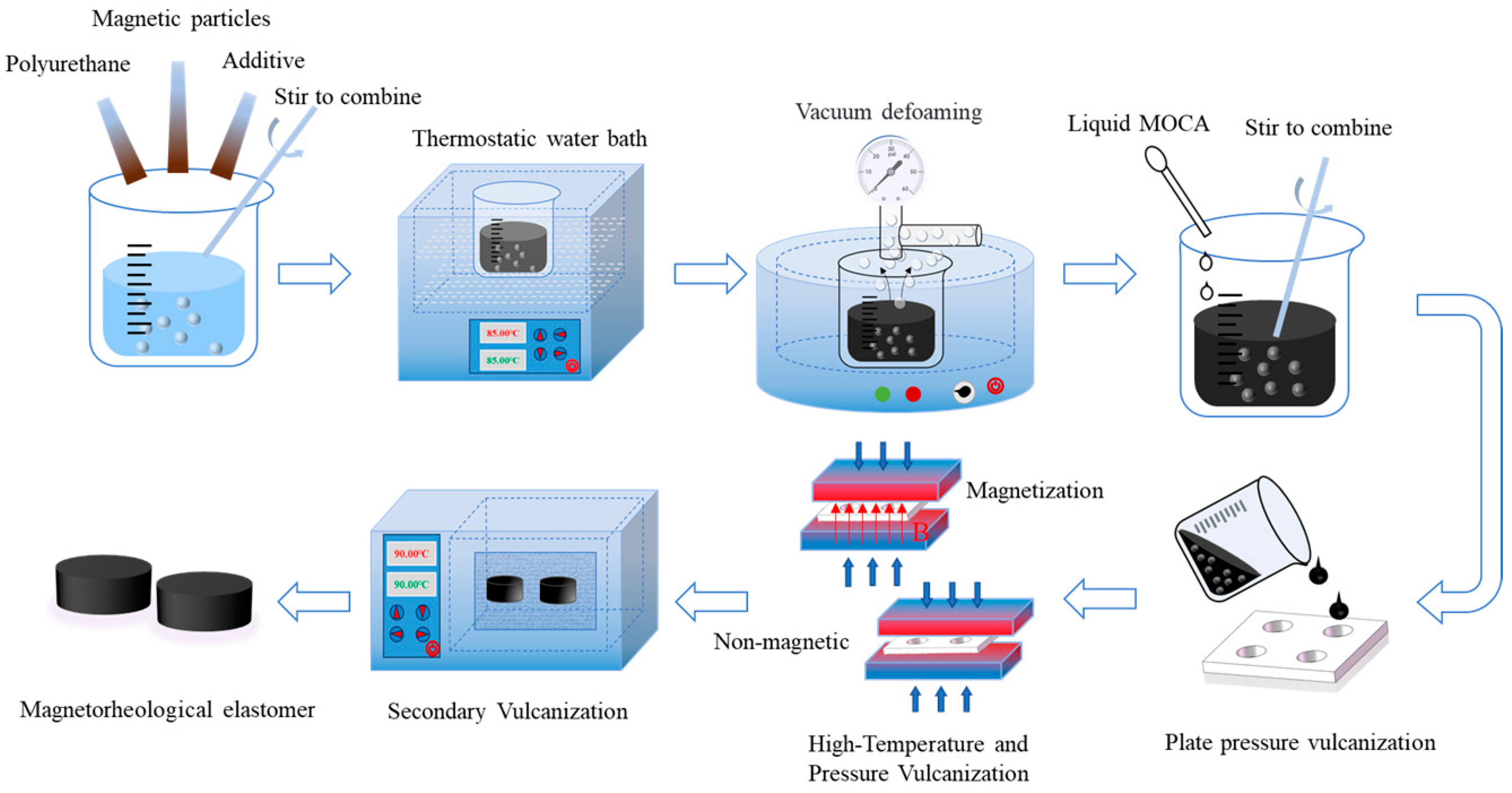
2.2. Sample Preparation
- (1)
- Preheating: Preheating operations include preheating the mold and preheating the polyurethane prepolymer. Before preheating the mold, it is necessary to spray a release agent on the inner surface of the mold to ensure the smooth demolding of the sample after molding, and then place it in a vulcanizing machine with a temperature set at 120 °C for preheating. Next, the polyurethane prepolymer is weighed in the balance and preheated in an 80 °C water bath. The purpose of preheating polyurethane prepolymers is to reduce their viscosity and enable the even distribution of carbonyl iron powder.
- (2)
- Mixing: This step is to weigh the corresponding mass of carbonyl iron powder and polyurethane prepolymer in proportion and stir them thoroughly, then weigh an appropriate amount of the additive and mix them together.
- (3)
- Bubble extraction: As the presence of bubbles in the sample can affect its performance, a vacuum defoamer is required to extract bubbles from the mixture.
- (4)
- First vulcanization: The mixture obtained is poured from the above steps into a preheated mold and then placed from the mold into the vulcanizing machine. The vulcanization temperature is set to 120 °C, and the vulcanization time is set to 30 min.
- (5)
- Second vulcanization: After the sample of the first vulcanization has cooled down, necessary trimming is carried out to remove excess parts, and then it is placed in a drying oven for the second vulcanization. The vulcanization temperature should be maintained at 90 °C, and the vulcanization time should be 6–8 h. To ensure the accuracy of the experiment, four samples should be prepared for each set of parameters. The PU-MREs prepared in this study are shown in Table 1.
2.3. Testing Methods
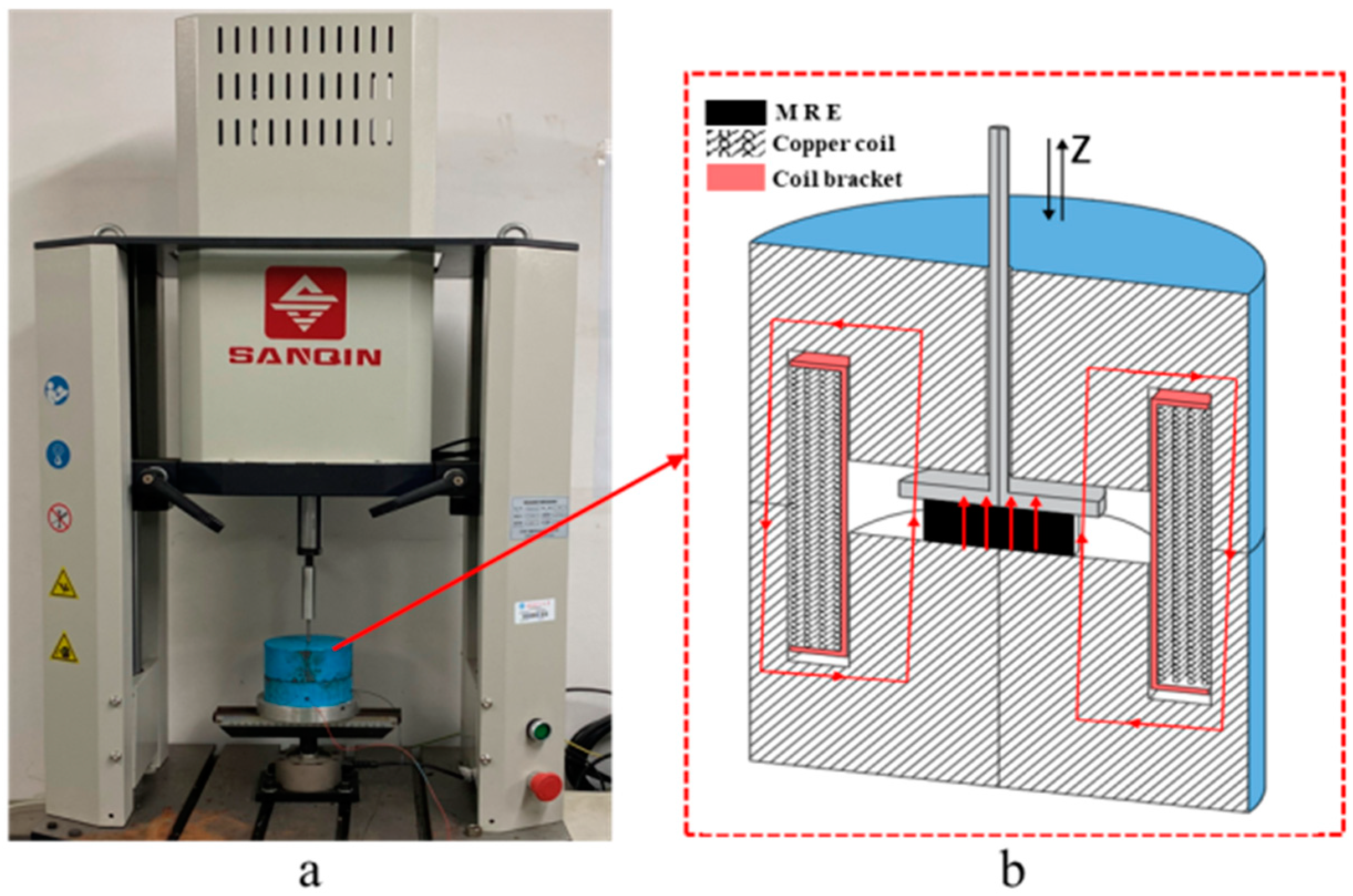
2.3.1. Static Magnetic Compression Performance Testing
- Purpose of Testing
- Testing Method
2.3.2. Magnetic Friction Coefficient Test
- Testing purpose
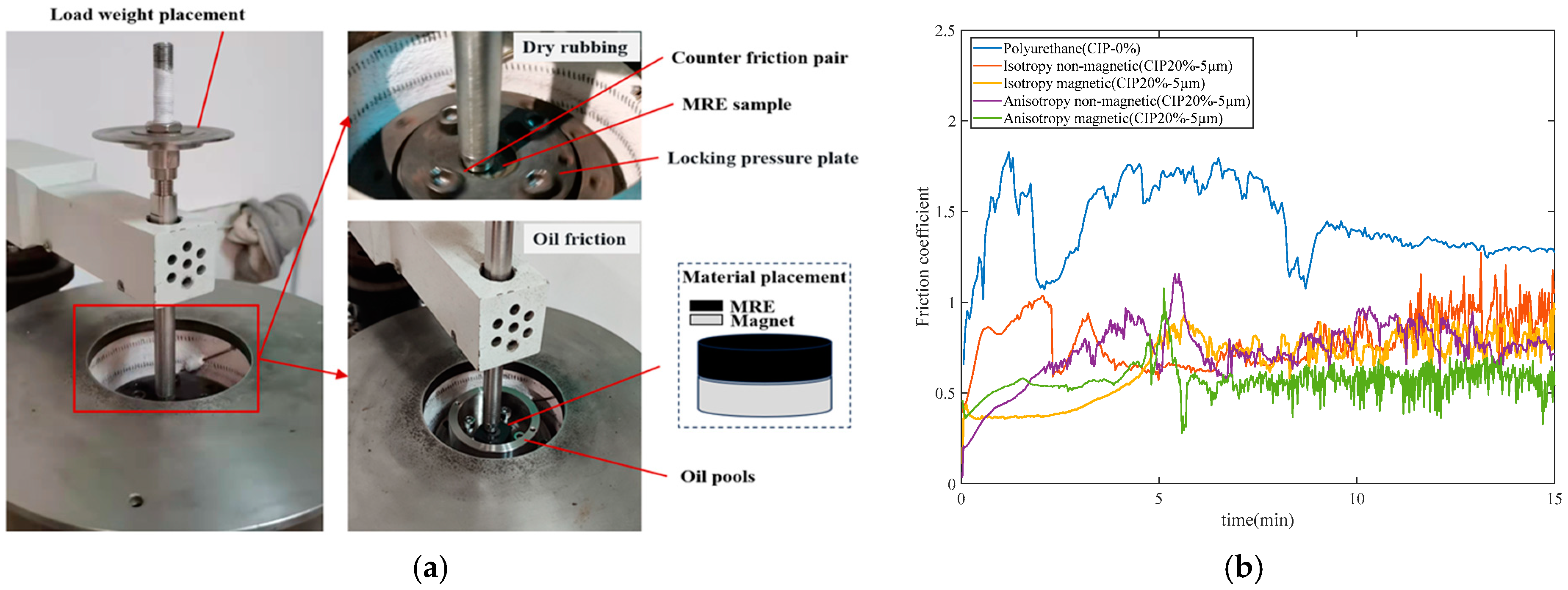
- Testing method
3. Results
3.1. Static Magnetic Compression Performance Testing
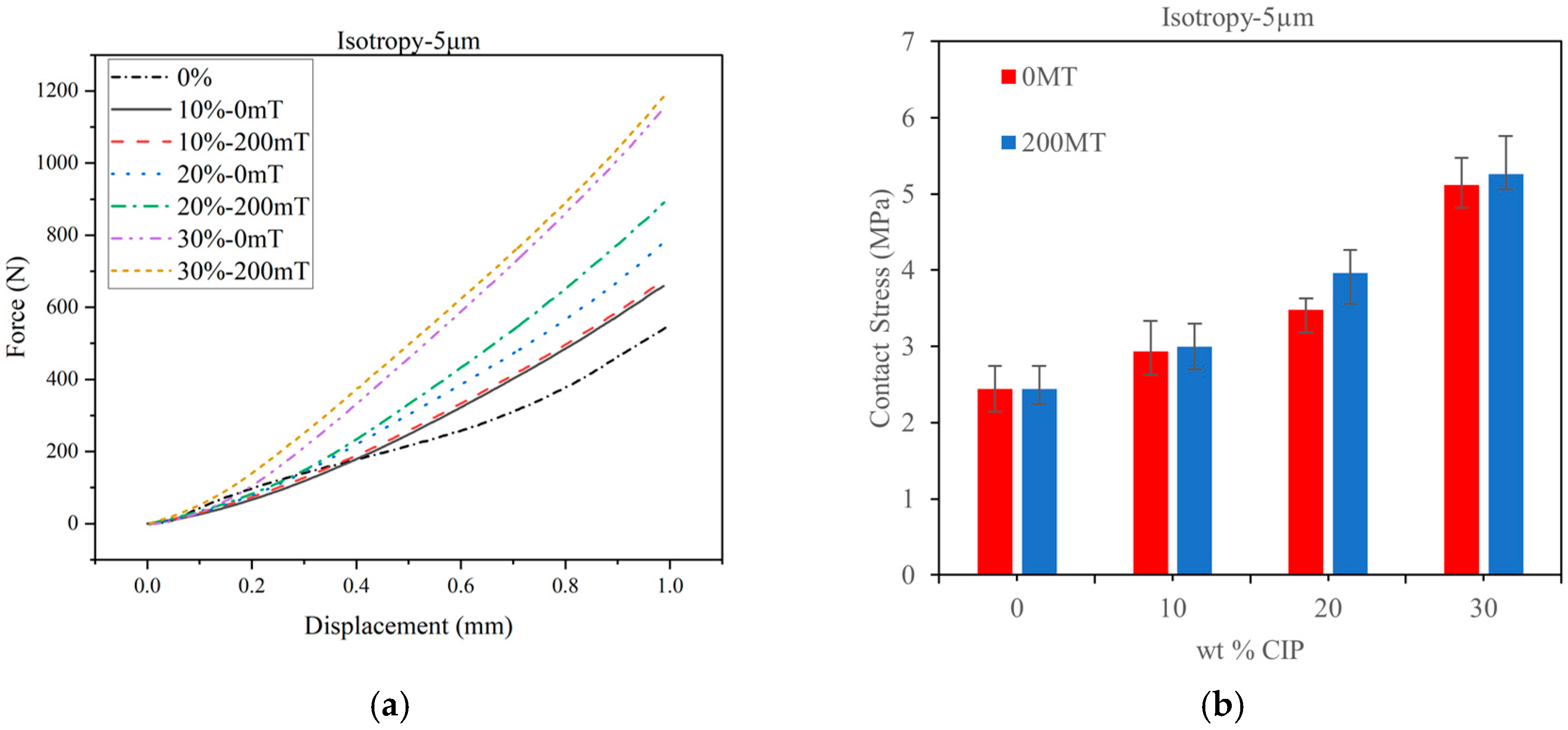
3.1.1. Static Compression Test Results of Isotropic Specimens
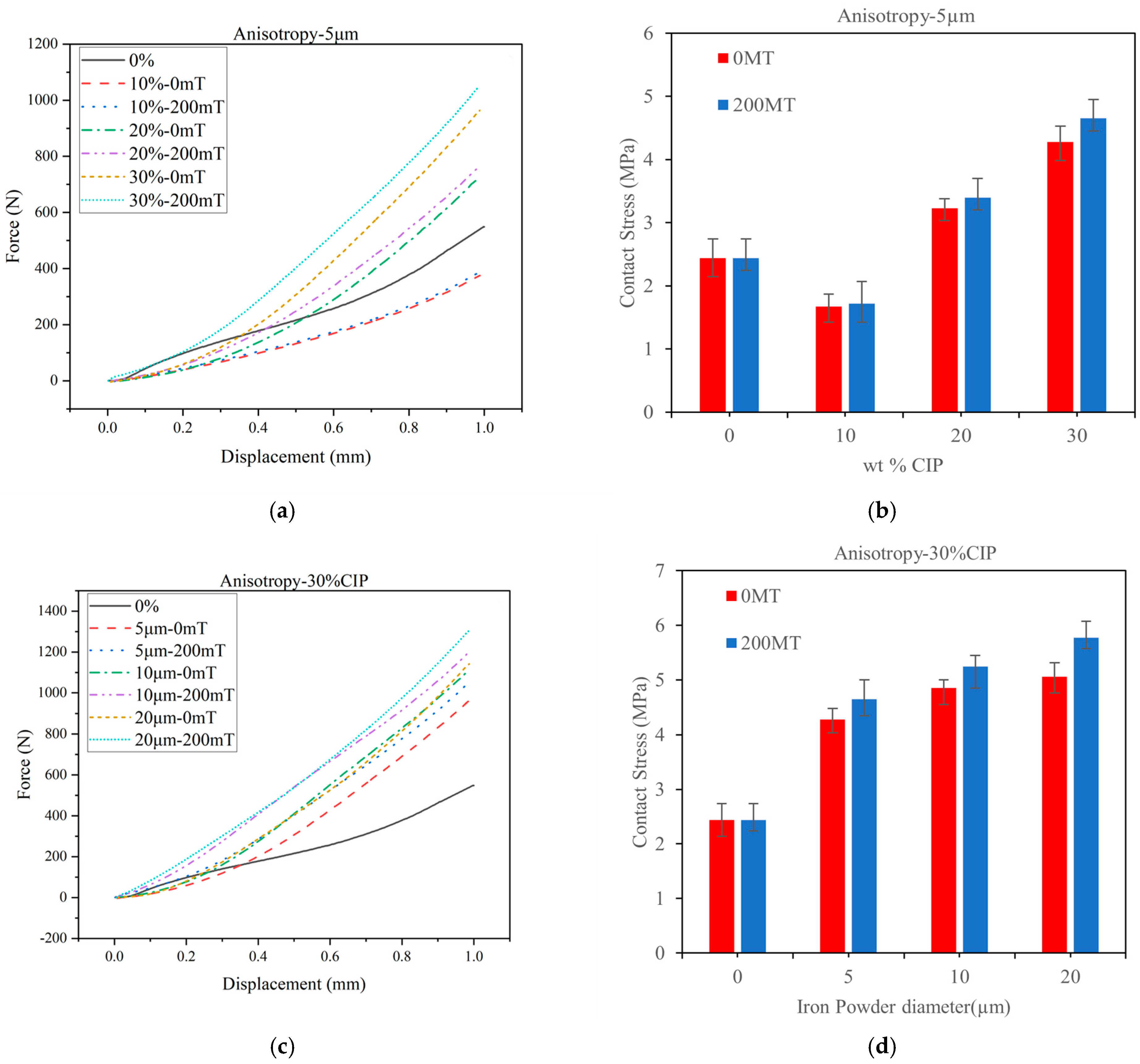
3.1.2. Experimental Results of Static Compression on Anisotropic Specimen
3.2. Magnetic Friction Coefficient Test
Testing Results
4. Discussion
5. Conclusions
Author Contributions
Funding
Data Availability Statement
Acknowledgments
Conflicts of Interest
Abbreviations
| PU | Polyurethane |
| MRE | Magnetorheological elastomer |
| CIP | Carbonyl iron powder |
| MOCA | 3,3′-dichloro-4,4′–diaminodiphenylmethane or di-o-chlorodiphenylmethane |
References
- Cheng, G.; Guo, F.; Zang, X.; Zhang, Z.; Jia, X.; Yan, X. Failure Analysis and Improvement Measures of Airplane Actuator Seals. Eng. Fail. Anal. 2022, 133, 105949. [Google Scholar] [CrossRef]
- Tan, G.; Fan, Q.; Tan, F.; Wang, D.; Zhang, S. Advances in Tribology on Elastomer Sealing and Its Future Trends for the Huge Machinery. Tribology 2016, 36, 659–666. [Google Scholar]
- Cao, W.-H.; Gong, J.; Wang, H.-G.; Gao, G.; Qi, Y.; Yang, D.-Y. Numerical Simulation on Wear-Thermal-Stress Coupling Behavior of Cap-Seal Seal and Optimization Design. J. Zhejiang Univ. 2019, 53, 258–267. [Google Scholar]
- McKee, M.; Gordaninejad, F. Reciprocating Shaft Seals for High-Temperature and High-Pressure Applications: A Review. J. Tribol. 2018, 140, 032202. [Google Scholar] [CrossRef]
- Qian, L.-J.; Xin, F.-L.; Bai, X.; Wereley, N.M. State Observation–Based Control Algorithm for Dynamic Vibration Absorbing Systems Featuring Magnetorheological Elastomers: Principle and Analysis. J. Intell. Mater. Syst. Struct. 2017, 28, 2539–2556. [Google Scholar] [CrossRef]
- Hoang, N.V.; Zhang, N.; Li, W.; Du, H. Development of a Torsional Dynamic Absorber Using a Magnetorheological Elastomer for Vibration Reduction of a Powertrain Test Rig. J. Intell. Mater. Syst. Struct. 2013, 24, 2036–2044. [Google Scholar] [CrossRef]
- Rahmat, M.S.; Hudha, K.; Abd Kadir, Z.; Nuri, N.R.M.; Amer, N.H.; Abdullah, S. Modelling and Control of a Magneto-Rheological Elastomer for Impact Reduction. J. Mech. Eng. Sci. 2019, 13, 5259–5277. [Google Scholar] [CrossRef]
- Behrooz, M.; Wang, X.; Gordaninejad, F. Performance of a New Magnetorheological Elastomer Isolation System. Smart Mater. Struct. 2014, 23, 045014. [Google Scholar] [CrossRef]
- Gu, X.; Yu, Y.; Li, Y.; Li, J.; Askari, M.; Samali, B. Experimental Study of Semi-Active Magnetorheological Elastomer Base Isolation System Using Optimal Neuro Fuzzy Logic Control. Mech. Syst. Signal Process. 2019, 119, 380–398. [Google Scholar] [CrossRef]
- Lian, C.; Lee, K.-H.; Lee, C.-H. Friction and Wear Characteristics of Magneto-Rheological Elastomers Based on Silicone/Polyurethane Hybrid. J. Tribol. 2015, 137, 031607. [Google Scholar] [CrossRef]
- Parker Hannifin Corporation O-Ring eHandbook—O-Ring & Engineered Seals Division | Parker US. Available online: https://www.parker.com/us/en/divisions/o-ring-and-engineered-seals-division/resources/oring-ehandbook.html (accessed on 8 February 2025).
- Sun, L.; Jiang, H. Design, Preparation and Properties of Polyurethane Dispersions via Prepolymer Method. Molecules 2023, 28, 625. [Google Scholar] [CrossRef] [PubMed]
- Huang, G.; Yang, T.; He, Z.; Yu, L.; Xiao, H. Polyurethane as a Modifier for Road Asphalt: A Literature Review. Constr. Build. Mater. 2022, 356, 129058. [Google Scholar] [CrossRef]
- Akindoyo, J.O.; Beg, M.; Ghazali, S.; Islam, M.R.; Jeyaratnam, N.; Yuvaraj, A.R. Polyurethane Types, Synthesis and Applications–A Review. Rsc Adv. 2016, 6, 114453–114482. [Google Scholar] [CrossRef]
- Sapouna, K.; Xiong, Y.P.; Shenoi, R.A. Dynamic Mechanical Properties of Isotropic/Anisotropic Silicon Magnetorheological Elastomer Composites. Smart Mater. Struct. 2017, 26, 115010. [Google Scholar] [CrossRef]
- Jaafar, M.F.; Mustapha, F.; Mustapha, M. Review of Current Research Progress Related to Magnetorheological Elastomer Material. J. Mater. Res. Technol. 2021, 15, 5010–5045. [Google Scholar] [CrossRef]
- Li, S.; Liang, Y.; Li, Y.; Li, J.; Zhou, Y. Investigation of Dynamic Properties of Isotropic and Anisotropic Magnetorheological Elastomers with a Hybrid Magnet Shear Test Rig. Smart Mater. Struct. 2020, 29, 114001. [Google Scholar] [CrossRef]
- Erenchun, A.; Blanco, B.; Gil-Negrete, N.; Wang, B.; Kari, L. Effect of Lubrication on the Mechanical Behavior of Magnetorheological Elastomers in Compression Mode. Polym. Test. 2022, 111, 107617. [Google Scholar] [CrossRef]
- GB/T 7757-2009; Rubber, Vulcanized or Thermoplastic—Determination of Compression Stress-Strain Properties. General Administration of Quality Supervision & Inspection and Quarantine of the People’s Republic of China. China National Standardization Administration: Beijing, China, 2009.
- Fereidooni, A.; Martins, A.; Wickramasinghe, V.; Suleman, A. Fabrication and Characterization of Highly Controllable Magnetorheological Material in Compression Mode. J. Intell. Mater. Syst. Struct. 2020, 31, 1641–1661. [Google Scholar] [CrossRef]
- Kohutiar, M.; Krbata, M.; Escherova, J.; Eckert, M.; Mikus, P.; Jus, M.; Polášek, M.; Janík, R.; Dubec, A. The Influence of the Geometry of Movement during the Friction Process on the Change in the Tribological Properties of 30CrNiMo8 Steel in Contact with a G40 Steel Ball. Materials 2023, 17, 127. [Google Scholar] [CrossRef] [PubMed]
- Lian, C.; Lee, K.-H.; Choi, S.; Lee, C. A Study of the Magnetic Fatigue Properties of a Magnetorheological Elastomer. J. Intell. Mater. Syst. Struct. 2018, 30, 749–754. [Google Scholar] [CrossRef]
- Li, R.; Li, X.; Li, Y.; Yang, P.; Liu, J. Experimental and Numerical Study on Surface Roughness of Magnetorheological Elastomer for Controllable Friction. Friction 2020, 8, 917–929. [Google Scholar] [CrossRef]
- Li, R.; Li, X.; Yang, P.; Liu, J.; Chen, S. The Field-Dependent Surface Roughness of Magnetorheological Elastomer: Numerical Simulation and Experimental Verification. Smart Mater. Struct. 2019, 28, 085018. [Google Scholar] [CrossRef]
- Gedde, U.W.; Hedenqvist, M.S.; Hakkarainen, M.; Nilsson, F.; Das, O. Applied Polymer Science; Springer Nature: Berlin/Heidelberg, Germany, 2021; ISBN 978-3-030-68472-3. [Google Scholar]


| No. | Type | CIP Content | CIP Particle Size/µm |
|---|---|---|---|
| 0 | - | - | - |
| 1 | Isotropy | 10% | 5 |
| 2 | Isotropy | 20% | 5 |
| 3 | Isotropy | 30% | 5 |
| 4 | Isotropy | 30% | 10 |
| 5 | Isotropy | 30% | 20 |
| 6 | Anisotropy | 10% | 5 |
| 7 | Anisotropy | 20% | 5 |
| 8 | Anisotropy | 30% | 5 |
| 9 | Anisotropy | 30% | 10 |
| 10 | Anisotropy | 30% | 20 |
| No. | Type | CIP Content/Vol% | CIP Particle Size/µm | Static Compression Modulus (MPa) | |
|---|---|---|---|---|---|
| No Magnetic | Magnetic | ||||
| 0 | - | - | - | 9.74 | 9.74 |
| 1 | Isotropy | 10% | 5 | 11.71 | 12.01 |
| 2 | Isotropy | 20% | 5 | 13.91 | 15.84 |
| 3 | Isotropy | 30% | 5 | 20.48 | 21.06 |
| 4 | Isotropy | 30% | 10 | 10.59 | 11.44 |
| 5 | Isotropy | 30% | 20 | 14.94 | 15.48 |
| 6 | Anisotropy | 10% | 5 | 6.67 | 6.90 |
| 7 | Anisotropy | 20% | 5 | 12.91 | 13.58 |
| 8 | Anisotropy | 30% | 5 | 17.12 | 18.62 |
| 9 | Anisotropy | 30% | 10 | 19.39 | 21.00 |
| 10 | Anisotropy | 30% | 20 | 20.25 | 23.07 |
Disclaimer/Publisher’s Note: The statements, opinions and data contained in all publications are solely those of the individual author(s) and contributor(s) and not of MDPI and/or the editor(s). MDPI and/or the editor(s) disclaim responsibility for any injury to people or property resulting from any ideas, methods, instructions or products referred to in the content. |
© 2025 by the authors. Licensee MDPI, Basel, Switzerland. This article is an open access article distributed under the terms and conditions of the Creative Commons Attribution (CC BY) license (https://creativecommons.org/licenses/by/4.0/).
Share and Cite
Zhao, X.; Appiah, E.; Tang, H. Study on the Magnetic Contact Mechanical Properties of Polyurethane-Based Magnetorheological Elastomer Sealing Materials. Lubricants 2025, 13, 88. https://doi.org/10.3390/lubricants13020088
Zhao X, Appiah E, Tang H. Study on the Magnetic Contact Mechanical Properties of Polyurethane-Based Magnetorheological Elastomer Sealing Materials. Lubricants. 2025; 13(2):88. https://doi.org/10.3390/lubricants13020088
Chicago/Turabian StyleZhao, Xiuxu, Emmanuel Appiah, and Haile Tang. 2025. "Study on the Magnetic Contact Mechanical Properties of Polyurethane-Based Magnetorheological Elastomer Sealing Materials" Lubricants 13, no. 2: 88. https://doi.org/10.3390/lubricants13020088
APA StyleZhao, X., Appiah, E., & Tang, H. (2025). Study on the Magnetic Contact Mechanical Properties of Polyurethane-Based Magnetorheological Elastomer Sealing Materials. Lubricants, 13(2), 88. https://doi.org/10.3390/lubricants13020088