Article

Research on Debris Characteristics and Wear Mechanism of Gear Material 18CrNiMo7-6 Used in Mining Reducer Under Dust-Contaminated Lubrication

1
Coal Mining Equipment in Shanxi Key Laboratory, Taiyuan 030024, China
2
College of Mechanical Engineering, Taiyuan University of Technology, Taiyuan 030024, China
3
General Engineering Research Institute, Liverpool John Moores University, Liverpool L3 3AF, UK
4
College of Environmental Science and Engineering, Tongji University, Shanghai 200092, China
*
Author to whom correspondence should be addressed.
Lubricants 2025, 13(3), 107; https://doi.org/10.3390/lubricants13030107
Submission received: 15 January 2025 / Revised: 22 February 2025 / Accepted: 27 February 2025 / Published: 28 February 2025

Abstract

:
The lubrication of mining reducer is subjected to the contamination of coal rock dust, and this contamination has extremely serious influence on the wear life of reducers. This paper examines the effects of coal dust and rock dust contamination on the wear of mine gearboxes, especially the wear mechanisms and particle characteristics under lubrication conditions of coal dust and rock dust mixtures of different particle sizes and contents. In the paper, 18CrNiMo7-6 alloy steel was used as the reducer gear material to simulate the actual working conditions, and friction and wear tests were conducted by CFT-1 comprehensive tester to analyze the wear particle characteristics under different contamination conditions. In the experiment, 80-mesh and 200-mesh coal dust and silica particles were used (80-mesh pore size is about 180 μm; 200-mesh pore size is about 75 μm), and different mass fractions of contaminant mixtures were set. The results show that under 80-mesh coal dust contamination, punctate pits, scratches and green halos appeared on the surface of wear particles, and the corrosion and abrasive effects were enhanced when the concentration increased, while 200-mesh coal dust contamination was characterized by black pits and green halos, and the abrasive effect was not obvious. Silica contamination showed significant cutting effects with red oxide wear particles. The synergistic effect of the two contaminants accelerated the wear of the material, and the wear particles were characterized by delamination, flaking and black pits. The study shows that the concentration and type of contaminants have a significant effect on the wear performance of the reducer.

1. Introduction

The 18CrNiMo7-6 is a low-carbon alloy steel that has become a common choice for key components, such as transmission gears, in heavy machinery and equipment due to its high strength, high toughness and good wear resistance as excellent mechanical and machining properties [1,2,3,4,5]. It has important applications, especially in key components of coal mining equipment, such as gears, bearings and transmissions. Coal mining equipment usually works in extremely complex environments, and the equipment is prone to face various wear and corrosion problems under the conditions of high loads and prolonged operation. During coal mining operations, drilling, crushing and transportation generate large amounts of coal dust and rock dust, which are suspended in the air or deposited on the surface of the equipment and are prone to entering the lubrication system, leading to lubricant contamination. The entry of coal dust and rock dust into the lubrication system as external contaminants can significantly change the nature of the lubrication medium, which in turn affects the performance and service life of the equipment. Although the surface of the alloy has been heat-treated during the manufacturing process, resulting in excellent mechanical properties and wear resistance, its wear behavior under the conditions of contamination lubrication of coal and rock dust has not been fully investigated, especially the effect of contamination lubrication on the wear of metal materials, the characteristics of abrasive grains under contamination lubrication and the effect of coal and rock dust alone or in mixed contamination on the characteristics of abrasive grains and wear mechanism. In addition, general gearboxes typically operate in more standard industrial environments with lighter loads and relatively lower types and concentrations of contaminants. Mining gearboxes, on the other hand, operate in harsh mining environments and are often exposed to extreme conditions such as high loads, strong vibrations, particulate contamination (e.g., coal dust, rock dust, etc.) and temperature fluctuations. During the operation of mining gearboxes, contaminants such as coal dust and rock dust not only directly cause mechanical wear, but also accelerate the oxidation reaction of alloying elements, forming different types of wear particles. Iron spectral images of ordinary gearboxes usually cannot accurately represent the effects of these contaminants on the morphology and composition of wear particles, and the wear mechanisms induced by these contaminants may be significantly different from the conventional wear behavior. These conditions make the wear particle characteristics, wear behaviors and contaminant effects of mining gearboxes significantly different from those of conventional gearboxes.
Several scholarly research efforts have been currently focusing on the effects of contaminants on frictional wear. Salehi et al. [6,7,8] explored how diesel fuel contamination affects oil functionality by leading to oil dilution and carbon formation and investigated how soot particles affect wear and friction through wear and adsorption of additives. Ramadan Mohamed Ahmed [9] investigated the effect of sand contamination on friction and wear behavior during a lubricated sliding process and examined the effect of sand concentration and particle size on the sliding friction and wear of piston ring segments against cylinder liners in a lubricated environment. MR Sari et al. [10,11] investigated the wear behavior in sliding friction contact, especially under the lubrication conditions contaminated by particles, explored the effect of contaminated particles on the wear mechanism and investigated the effect of factors such as particle size, shape and hardness on the wear rate and the wear mechanism through experimental and theoretical analyses. Hu Ningning, Singh Rabesh Kumar and Yan Zhiyong et al. [12,13,14] investigated the effects of particle-containing lubricants, high-temperature contaminants and hydraulic oil contamination on the tribological properties and wear behavior of mechanical equipment, railroad wheel materials and hydraulic systems, respectively, and analyzed the changing rules of friction, wear and wear resistance of different particle types, concentrations and contamination factors. Boldyrev et al. [15], on the other hand, investigated the effects of contaminants such as moisture, SiO2 and copper on the anti-wear performance of hydraulic fluids through experiments, used orthogonal test methods to find out the main factors affecting the anti-wear performance of hydraulic fluids and compared the performance of different brands of hydraulic fluids under contaminated conditions. At the same time, some scholars conducted research on how to qualitatively and quantitatively analyze the wear debris grains by using a ferropraseodymium instrument. Li Zhuangqiong [16] monitored and analyzed their wear particles by iron spectroscopy to explore the law of equipment wear and its influencing factors. Xiaoxiao Ma [17] designed an on-line rotary ferrography analysis system integrating sampling, spectrometry, cleaning and image acquisition functions and optimized and verified the performance of its key modules. Li Linning [18] and others designed a rotary ferrography spectral sheet debris grain coverage measurement and analysis system to achieve efficient and stable quantitative analysis of iron spectral debris grain deposition parameters. Li Guangsheng [19] explored how to quantify the results of qualitative analysis of iron spectra to achieve the method of detecting their wear conditions. Zhou Junli [20] and others constructed a comprehensive evaluation system of wear, which effectively judged the severity level of mechanical equipment wear.
Coal and rock dust contamination has a serious impact on the wear life of mining machinery and equipment, especially at high contact pressures and high temperatures, where the contaminants significantly accelerate the degradation of material surfaces through oxidative and abrasive wear effects [21,22,23,24]. It has been shown that the particle size and composition of coal and rock dust, as well as their interaction with the lubricating medium, directly influence the wear mechanism. For example, the microstructure and oxidation properties of 18CrNiMo7-6 steel, which is a commonly used material for heavy-duty gears, are decisive for anti-wear performance at high temperatures [3,25]. There have been many studies on the characteristics of abrasive particles and wear mechanisms under different lubrication and contamination conditions. For example, in complex mining conditions, the combined effect of high temperatures and corrosive environments will lead to pitting, scratching and oxide film detachment on the surface of 18CrNiMo7-6 alloy steel, and these phenomena directly accelerate the fatigue failure of the material. In addition, the rupture and repair process of the oxide film and the friction effect of contaminant particles have a synergistic effect, which further deteriorate the wear performance of the material [26,27,28,29].
Although there have been studies exploring the effects of contaminants on lubrication and wear and the observation of debris particles, there are still some deficiencies in the study of wear under the conditions of contaminated lubrication of coal and rock dust, mainly including the following aspects: the research object is mostly limited to conventional particle contamination, and there is a lack of in-depth research on the specific characteristics of coal and rock dust; there is insufficient micro-analysis of wear mechanisms; and there is a lack of multivariate effects on the systematic research. These shortcomings limit the practicality and feasibility of the research conclusions in practical applications. Therefore, it is necessary to further study the lubrication and wear behavior under the contamination of coal and rock dust. Past studies have mainly focused on the characteristics of wear particles under normal working conditions, while coal mining machinery and equipment usually work in extreme environments, and their lubrication conditions are different from those of ordinary gearboxes, which leads to significant differences in the morphology of abrasive debris produced during the wear process. Therefore, it is not scientific to judge according to conventional standards. Through experimental research and mechanism analysis, this paper aims to summarize the abrasive particle characteristics under the lubrication conditions of coal and rock dust contamination, so as to more accurately judge the cause and severity of wear. The study not only provides a theoretical basis for the wear fault diagnosis of coal mine mechanical equipment but also helps to formulate effective maintenance measures to improve the operational reliability and extend the service life of the equipment.

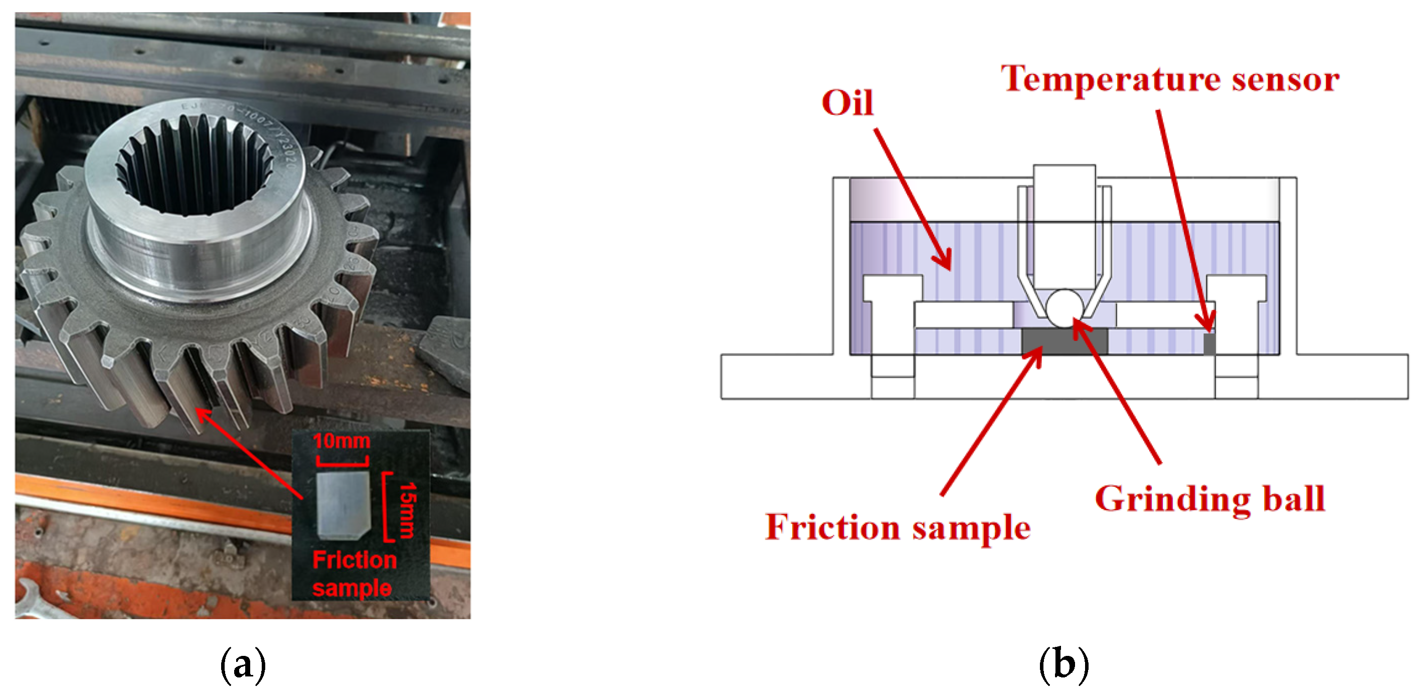
2. Investigation Test Setup

The tests select roadheader gear material 18CrNiMo7-6 (hardness approximately 7.06 GPa) as the substrate, and 18CrNiMo7-6 gear material undergoes a heat treatment process of normalizing, carburizing, quenching and tempering. It is first normalized to refine the grain, followed by carburizing at a high temperature to increase the surface carbon content, then quenching at a reduced temperature to obtain a high-hardness martensitic organization and finally tempering to relieve stress and improve toughness [30]. The chemical composition and content of the material is shown in Table 1. L-CKD 220, a loaded industrial closed gear oil (L-CKD 220) with excellent anti-wear, anti-oxidation, anti-corrosion and anti-foam properties and suitable for gear systems subjected to high loads and shock loads, is selected as the lubricant (the properties are shown in Table 2), and coal dust (anthracite), rock dust (silica) and a mixture of these two are considered as a set of contaminants. Experiments are configured with a total of 13 groups of oil specimens, according to the size of the particles entering the gearbox case, and will be divided into two types of contaminants of large particles (80 mesh) and small particles (200 mesh), respectively, according to the mass fractions of 0.5 per cent, 1 per cent and 3 per cent, in which mixed contamination is in accordance with the ratio of coal and rock 2:1 mixed. The specific groups are shown in Table 3.
Tests are conducted using the CFT-1 Friction Wear Tester (manufactured by Lanzhou Zhongke Kaihua Technology Development Co., Ltd., Lanzhou, China) to simulate the friction behavior of a material in a lubricated condition. First, a specimen is cut from a gear tooth face and fixed to the bottom of the fixture of the friction machine. The upper specimen is selected with 5 mm diameter Si3N4 grinding balls (hardness approximately 14.7 GPa) to ensure stable loads and contact pressures and to ensure that the wear studies on the alloy materials are carried out under controlled conditions. The fixture is a slotted container, the specimen is fixed at the bottom of the container and the container is filled with lubricant liquid, which completely submerges the substrate, as shown in Figure 1. During the test, the friction machine simulates the friction state of gears in the working process by reciprocating motion. Specifically, the specimen will be sliding back and forth along a specific trajectory during the friction process, the motor speed is set at 800 r/min, the corresponding reciprocating speed is 0.13 m/s, friction distance is 5 mm, there is a fixed load (150 N) and different lubrication conditions and each group of tests is conducted for 30 min to study the friction behavior of the material under different contaminant concentrations and lubricant conditions. Ultimately, the analysis of the wear on the specimen surfaces enables the evaluation of the lubrication performance of the lubricant and its effect on the material wear.
After the completion of each group of tests, the spectra are prepared with the aid of a rotary ferrography, and the spectra are observed under a metallurgical microscope to extract the debris features. The morphology of the substrate after the test is observed by electron microscopy and the elemental composition are analyzed by Energy Dispersive Spectrometer (EDS), and the wear mechanism is analyzed and verified by combining with the friction coefficient. The test workflow is shown in Figure 2.

3. Test Result Observations

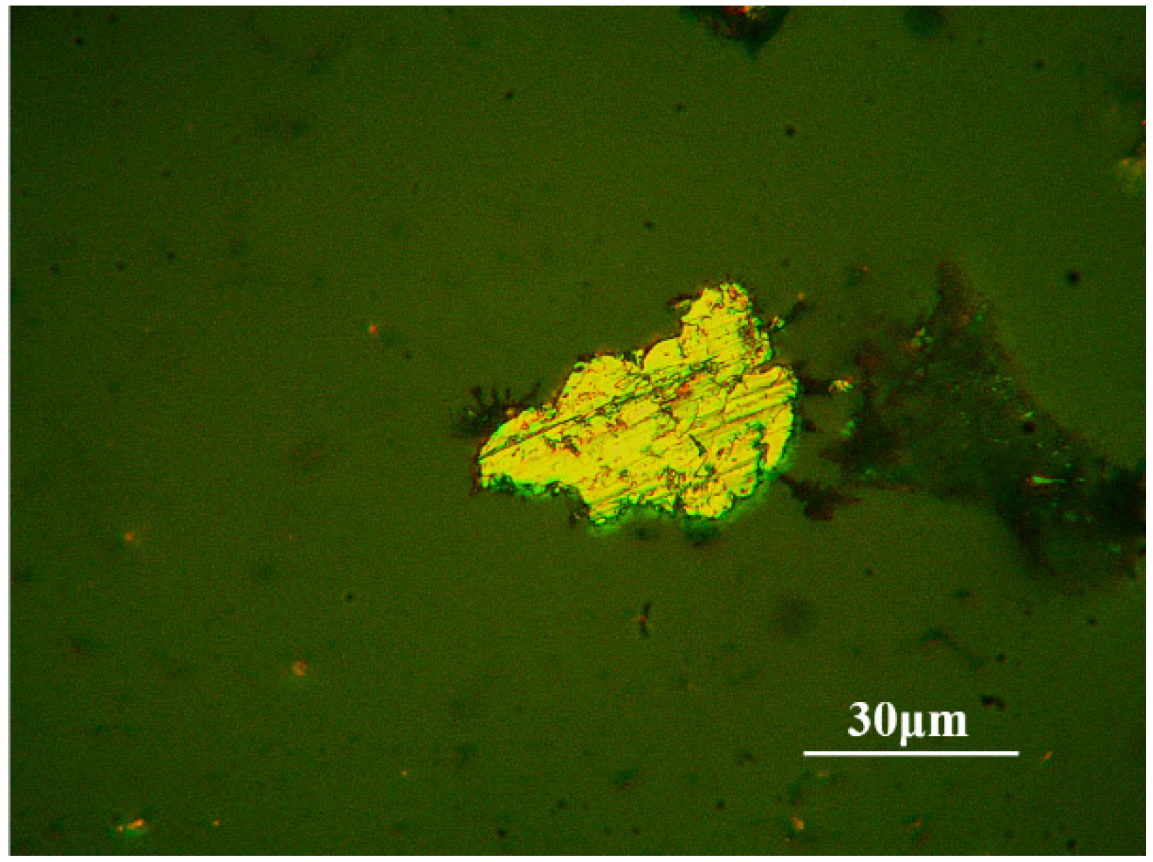
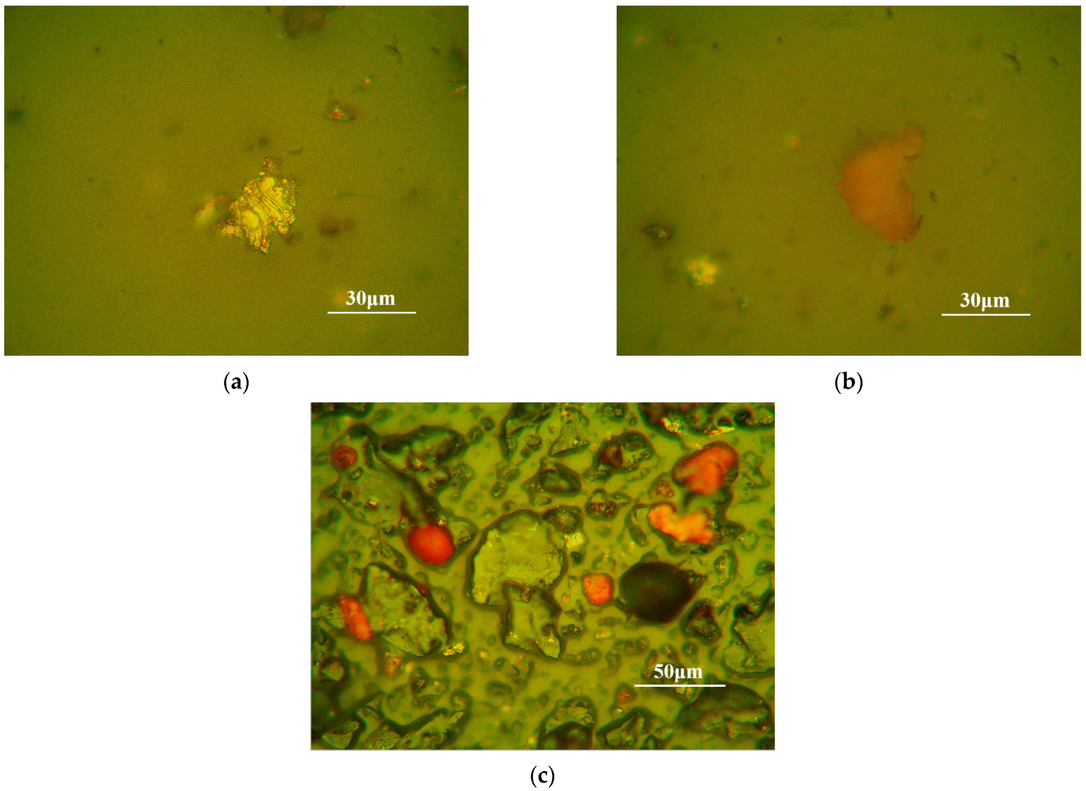
3.1. Contaminant-Free Debris Grain Characteristics

Figure 3 shows the ferrograph image of the iron wear debris particles after the friction wear test. As can be seen in Figure 3, the surface of the debris particles is smooth and retains its original metallic luster with no visible pits and clear edge contours. In this contamination condition, the number of abraded debris grains is small and has the same characteristics as Figure 3. The size of the debris grains does not exceed 55 μm, which shows that the wear is not serious.

3.2. Characterization of Debris Particles Under Coal Dust Contamination

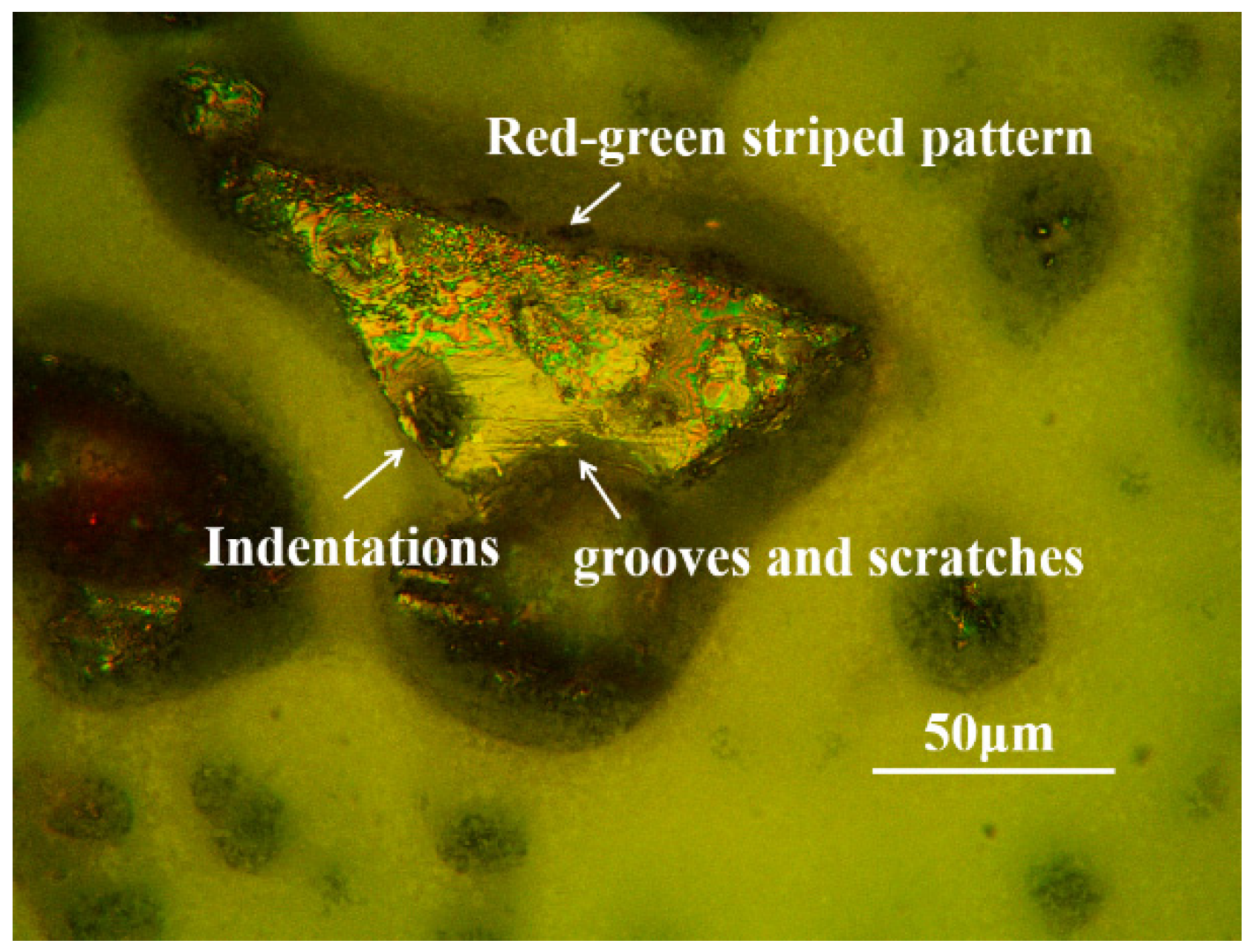
3.2.1. The 80-Mesh Coal Dust

Under 80-mesh coal dust contamination, the surface characteristics of the debris grains varied depending on the coal dust content. Figure 4 shows the microscopic images of iron debris grains of the 0.5% content test. Figure 5 shows the microscopic images of iron debris grains of the 1% content test. As can be seen from Figure 4, the surface of the debris grains containing 0.5% 80-mesh coal dust is relatively smooth with an irregular overall shape but smooth edges. As can be seen in Figure 5, the surface of the abraded grain of the lubricant fluid with 1% content of 80-mesh coal powder has a point-like pit, accompanied by some red and green streaks. This feature will be analyzed in detail in the next section on wear mechanisms. In addition, observing the whole field of view, it can be seen that the field of view is unevenly distributed with coal particles as well as mixed particles adhered by coal and debris grains, and so on.
Figure 6a,b show two different sets of iron debris grains under the lubrication medium of 3% content of 80-mesh pulverized coal, respectively. As shown in Figure 6a, the surface of the debris grains shows obvious black pits, with green halos distributed around the pits and embedded in the pits such as fine metal debris particles or red oxide particles. As shown in Figure 6b, the surface of the debris grains also has pits and cracks.

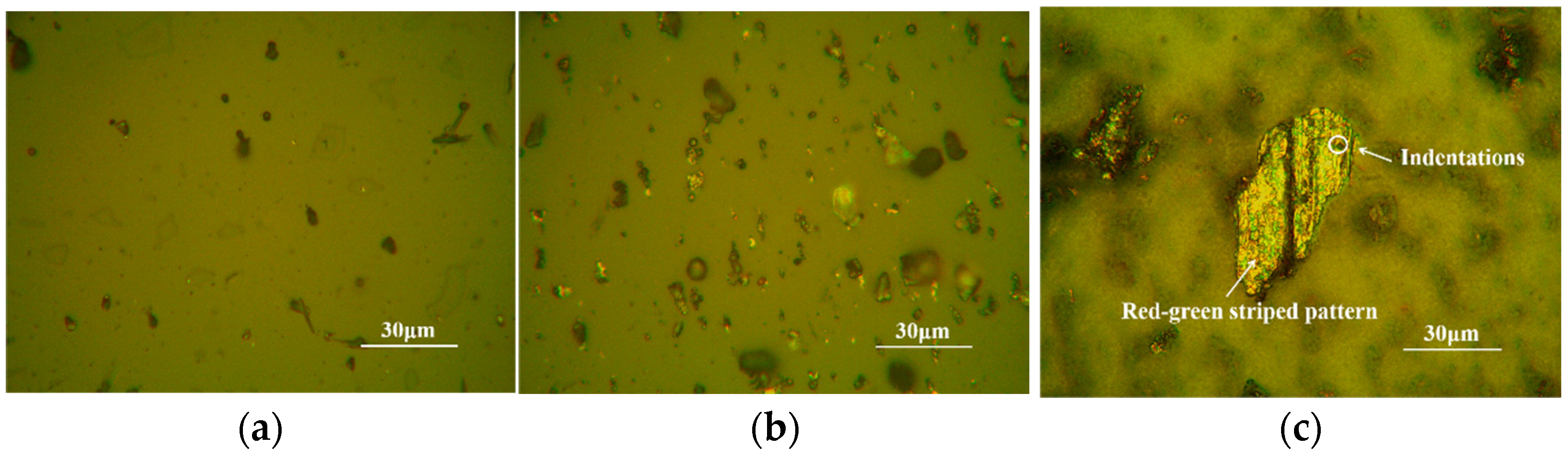
3.2.2. The 200-Mesh Coal Dust

Figure 7 shows the ferrograph images of iron debris grains after frictional wear tests with different contents of 200-mesh coal dust lubrication media. As shown in Figure 7a,b, the size of debris particles produced under 0.5% and 1% 200-mesh coal dust contamination is smaller than those produced under 80-mesh coal dust contamination, and the number of debris particles is also less than those produced under 80-mesh coal dust contamination conditions. Fatigue wear particles, as shown in Figure 7c, are usually particles formed by micro-cracking, peeling or rupturing of the material surface under repeated loading and stress. These particles usually have specific morphological characteristics, including irregular shape, low surface smoothness and often show signs of cracking or peeling. Fatigue particles often have surfaces with a distinct laminar structure or, in some cases, the edges of the particles may be characterized by crumbling or peeling. The fatigue wear particles under the lubrication condition of 200-mesh coal dust with 3% content have obvious black pits on the surface; and there is a green halo on the surface, which is similar to that under the lubrication condition of 80-mesh coal dust with 1% content, but the overall size and number of debris particles are smaller than that under the lubrication condition of 80-mesh coal dust with 3% content. Due to the large increase in coal dust content, the coal dust is ground to penetrate into the pits on the surface of the particles or adheres to the particle surface, and as a result, some of the particle debris grains show a significantly deeper surface color. Compared with the non-contaminated conditions, by the environmental contamination, the wear particles increased significantly, the surface roughness of the adhering wear particles increased significantly and a large number of pits and pockmarks appeared. These features reflect the significant changes in the morphology of the wear particles under coal dust contamination conditions. It also indicates that the adhesion effect is enhanced under this contamination condition due to the embedding of coal particles or the adhesion of coal dust at the friction interface.
Overall, when the content of coal dust gradually increases, the surface of the generated fatigue wear particles gradually produces more pits and cracks, accompanied by the generation of a more pronounced green halo, indicating that the intensity of wear gradually increases. However, the number of generated wear particles is not only related to the content of coal dust but also to the particle size of coal dust particles. When the particle size of coal dust particles is 200 mesh, the number of generated wear particles does not necessarily increase sharply even when the content reaches 3%; however, when the particle size of coal dust particles is 80 mesh, the number of generated wear particles increases sharply when the content reaches 3%. This suggests that larger pulverized coal particles (e.g., 80 mesh) have a more significant effect on wear at high contents, resulting in more wear particles being generated.

3.3. Characterization of Debris Grains Under Rock Dust Contamination

Figure 8 shows the ferrograph images of iron debris grains after frictional wear with different contents of 200-mesh rock dust lubrication media. As shown in Figure 8a, the debris grains in the lubricating medium containing 0.5% silica mainly appear as fatigue wear particles. Their long axis does not exceed 150 μm, and the short axis does not exceed 120 μm. These particles usually present flakes with irregular edges, fine pockmarks and scratches on the surface, and the most obvious feature is the oxidation of the surface due to high stress, which presents a dark or brown color. As shown in Figure 8b, the red oxide increases in the lubricating medium containing 1% silica compared to the lubricating medium containing 0.5% silica, but its size is not significantly larger. As shown in Figure 8c, more than 90% of the worn debris particles in the lubricating medium containing 3% silica are red oxides with different degrees of oxidation. A significant increase in red oxides was observed in the contaminated lubricating media compared to the wear particles generated when using uncontaminated lubricating media, along with a significant increase in the number of cutting debris particles.
It can therefore be concluded that red oxides are present in the debris grains in all three lubricating media with silica content. The long axis does not exceed 200 μm, the short axis does not exceed 150 μm and the surface is relatively rough. These oxide particles have various morphologies, rough surfaces and are easy to recognize in the iron spectrogram. The formation of these red oxides is mainly due to the high temperatures generated during the friction process, which causes oxidation of the metal surface, especially the formation of iron oxides from iron elements. Cutting debris particles were present in the debris grains in all three types of lubricating media with silica content. In lubricating media containing 3% silica, there are more cutting debris particles.
In addition, the surfaces of some of the debris grains show localized oxidation under all conditions of lubricating media containing rock dust due to the effect of frictional heat. Part of the area appears red (oxidized area), while part of the area maintains the original color of the metal (unoxidized area). It should be noted that the identification of red oxides in this study was based primarily on visual color changes observed in the wear particles. This approach provides useful qualitative insight. Future studies will incorporate more precise methods, such as EDS or X-ray diffraction, to confirm the chemical composition of the wear particles and provide a more comprehensive understanding of oxide formation.

3.4. Characterization of Debris Grains Under Mixed Contamination

Figure 9 shows the ferrograph images of iron debris grains after frictional wear carried out under mixed-contamination media, where (a) and (b) are the cutting debris particles generated under mixed-contamination media with 0.5% and 1% content, respectively. As shown in Figure 9, due to the presence of silica particles in the mixed-contamination lubrication conditions, the high-hardness silica particles play the main cutting role in the friction process, resulting in the generation of cutting debris particles in all lubrication media, and the presence of such particles makes the cutting effect more significant, especially in the 0.5% and 1% lubrication media conditions.
Figure 10 shows the ferrograph images of iron debris grains after frictional wear under 3% content mixed-contaminated media, where Figure 10a,b are two kinds of wear particles with different surface characteristics, respectively. As shown in Figure 10a, a part of the fatigue wear particles has a large number of pits of different sizes on their surfaces, and the residues inside the pits are of different colors, some of which are small metal particles while others are coal dust particles. These pits are areas where material has been removed, and coal residue may be embedded in them or oxides generated by friction on the surface of the object may also be embedded in them. The surface of the debris particles is marked with green streaks, while the outer ring of the pit exhibits a red color. The concentration of red areas around the pit is due to localized heating and oxidation during pit formation. As shown in Figure 10b, another part of these fatigue wear particles has unevenly distributed cracked pockmarks on the surface and are delaminated with distinct delamination edge lines.
At the same time, the high temperatures generated in the cutting process will accelerate the oxidation reaction of iron, generating red iron oxides. The oxidation reaction on the surface of the debris grain will also be accelerated relatively, accelerating the oxidation reaction of chromium on the surface of the debris grain, and the chromium oxide shows a green color on the surface of the debris grain. In contrast to the non-contaminated lubrication conditions, the wear particles generated under mixed-contamination lubrication conditions exhibit a combination of single contaminant characteristics of coal and rock dust, both in terms of the generation of a large number of red oxides and cutting debris particles, while a significant increase in the number of fatigue wear particles is also observed. The increase in red oxide indicates a significant increase in friction interface temperature under mixed-contamination lubrication conditions, which in turn leads to an accelerated rate of oxide generation. The increase in cutting debris particles reflects the increased shear during grinding due to physical embedding or a chemical reaction of coal and rock dust particles, leading to an elevated material removal rate. The significant increase in fatigue wear particles, on the other hand, exacerbated the fatigue damage of the alloy by the compounding effect of the surface coal and rock dust, especially under repeated cyclic stresses, and the synergistic contamination of coal and rock dust enhanced the stress concentration effect and crack extension rate. Taken together, the effects of mixed contamination on lubrication and wear mechanisms are complex, ranging from oxidative wear due to chemical reactions to cutting and fatigue wear due to mechanical actions.
Table 4 summarizes the characteristics of several different lubrication contamination scenarios.
Figure 11 shows the three-dimensional contours of the abrasion marks of the specimens under each test group. Figure 12 shows the amount of wear of the specimens under each test group. As can be seen from the figure, in the pulverized coal dust test group, except for the 80-mesh pulverized coal dust test group with a mass fraction of 3.0%, the abrasion amount of the rest of the groups is smaller than that of the control group; while the abrasion amount of test groups 7 to 12 containing rock dust is larger than that of the control group. Under the same mass fraction, the abrasion amount of the 80-mesh coal dust powder test group was slightly larger than that of the 200-mesh coal dust powder test group. The abrasion amount of the rock dust test group was overall smaller than that of the mixed-particulate test group. With the same type of particulate matter, the abrasion amount and depth of abrasion marks tended to increase with the increase in the mass fraction of particulate matter. The abrasion amounts of the 3.0% 200-mesh rock dust test group and the 1.0% and 3.0% 200-mesh mixed-particles test group were 1224.0%, 1314.0% and 1583.0% of the control group, respectively, and the abrasion marks had a higher bulge on both sides.

4. Wear Mechanism Analysis

4.1. Wear Mechanism Under Coal Dust Contamination

In coal dust-contaminated environments, coal dust particles adhere and interact with alloy workpiece surfaces upon contact, resulting in microscopic tearing of surfaces and transfer of metal particles. Coal particles roll or slide between oppositely moving surfaces, cutting the alloy surface. In addition, the mutual extrusion of the coal particles and the alloy surface generates strong shear and compressive stresses on the alloy surface, which gradually destroys the microstructure of the alloy surface, leading to local plastic deformation, crack sprouting and expansion of the material. With the continuous action of contact stress, the surface material is gradually scraped or sheared down by debris particles and eventually stripped to form wear particles. At the same time, under the action of cyclic load, the coal particles cause frequent changes in the surface stress of the alloy, forming a stress concentration point, which in turn generates micro-cracks. As the friction continues, the micro-cracks gradually expand, eventually leading to wear particle spalling.
Under high contents of coal dust contamination conditions, the surface of the alloy showed distinctive black craters and a greenish hue. Since coal dust contains a large amount of P and S elements, the P and S elements can be used in the EDS image to determine whether there is any contamination from coal dust. Figure 13, Figure 14 and Figure 15 show the EDS profiles of the debris grains under 80-mesh and 200-mesh coal dust contamination conditions as well as in the absence of contamination, respectively. It can be seen from the profiles that the elemental distribution on the surface of the debris grains changed significantly under the condition of coal dust contamination. In particular, the distribution of phosphorus (P) and sulphur (S) elements increased significantly, while the distribution of nickel (Ni), chromium (Cr), molybdenum (Mo) and other alloying elements changed significantly. Further observation of the debris grain surface reveals the distribution of green streaks. Both observations show that these green streaks are actually due to the film formed by the oxidation of chromium, nickel, molybdenum and other alloying elements at high temperatures and that the phosphorus, sulphur and other reactive components in the coal dust accelerated the oxidation reaction of the alloying elements in the abrasion process, which made the interference effect of the oxidized film even more pronounced, leading to the appearance of obvious red and green streaks in the reflected light. The red coloration of the outer rim of the pits on the alloy surface is closely related to the formation of iron oxide (Fe2O3). At high temperatures, the alloy reacts with oxygen to form iron oxide, and this concentration of red areas is consistent with localized heating and oxidation during crater formation. On this basis, the energy spectra were grayed out, and the numerical changes under the three contamination conditions were further quantified by calculating the total gray value of the images. As shown in Figure 16, total gray values of nickel (Ni), chromium (Cr) and molybdenum (Mo) under non-contaminated conditions are 1,098,837, 1,133,383 and 6,731,407, respectively, which are lower than those under 80-mesh and 200-mesh coal dust contamination conditions. The total ash values of these three alloying elements increased to 6,109,165, 7,959,148 and 25,435,628 under 80-mesh coal dust contamination, and these values further increased to 2,662,869, 2,465,149 and 13,060,168 under 200-mesh coal dust contamination, respectively. This result further suggests that the reactive elements in the coal dust not only accelerated the formation of the oxide film but also significantly influenced the distribution of alloying elements on the surface of debris particles, resulting in a significantly higher elemental content in the contaminated condition than in the non-contaminated condition. This also quantitatively verifies the aggravating effect of coal dust contamination on the wear process. With the continuous action of mechanical wear and temperature changes, the oxide film ruptures, leading to the appearance of pitting corrosion, and the corrosion products tend to be retained in the pits. At the same time, the area around the pits showed signs of repair of the oxide film, and these repair films appeared green in reflected light. These experimental results indicate that the reactive elements (e.g., phosphorus and sulphur) in the contaminants under coal dust contamination conditions produce more severe wear on the alloy surface by accelerating the oxidation reaction. In addition, the superimposed effects of cyclic and shear stresses not only prompted lamellar peeling and micro-crack generation of the surface material but also exacerbated the rupture of the oxide cover layer, further accelerating the surface fatigue and wear process.
Figure 17 and Figure 18 show the friction coefficient under 80-mesh and 200-mesh coal dust-contaminated media, respectively. As can be seen in Figure 17, the overall friction coefficient tends to increase with the increase in 80-mesh coal dust content, especially in the case of 3% coal dust content, where the friction coefficient reaches the highest value. This is due to the lower hardness of coal particles, which is about 0.4 GPa [31,32], in the friction process and is extruded into smaller particles, and in the larger, contact pressure is extruded into a dense sheet structure, covering the rough friction surface, which play a certain lubricating effect, so that the coefficient of friction is reduced; however, the lubricating oil in the coal dust of more than a certain mass fraction (too much coal dust in the slipping action will adhere to the contact surface) will result in slipping resistance, leading to extrusion adhesion effect and increased wear. This leads to the extrusion adhesion effect and the increase in the friction coefficient, which lead to the increase in wear [33]. This phenomenon suggests that the coarser coal particles exert greater mechanical forces on the alloy surface during friction, leading to increased adhesive and abrasive wear [34]. This is consistent with the previously mentioned analysis that 80-mesh coal dust particles are larger and have rougher surfaces, forming significant adhesive wear mainly through mechanical stripping actions. As can be seen in Figure 18, the friction coefficient of 200-mesh coal dust is relatively low and fluctuates less compared to 80-mesh coal dust. Even at 3% content, the increase in friction coefficient is not as significant as that of 80-mesh coal dust. This is due to the fact that the 200-mesh coal dust particles are smaller, and during the friction process, the physical grinding effect on the alloy surface is smaller, and the increase in friction coefficient is smoother due to the fact that the small part of the coal dust adheres to the surface, which slows down the cutting effect of the debris.
SEM photographs of the surface morphology of the workpieces contaminated with coal dust at different particle sizes and different mass fractions are shown in Figure 19 and Figure 20, respectively. As can be seen in Figure 19, under 80-mesh coal dust contamination, Figure 19a–c show features such as flaking and cratering on the surface of the workpieces gradually as the mass fraction of coal dust increases. More abrasion marks are formed in Figure 19a, which is due to the larger coal particles, and the rolling and sliding between the relative surfaces increase the cutting action. The surface material spalling is more obvious in Figure 19b,c, which is due to the increase in the number and pressure of the coal particles, the increase in the concentration of the surface stresses, the extrusion of the coal particles in the process of rolling on the surface and the chemical reaction between coal and the surface of the workpiece, which make the material surface more prone to peeling in the extrusion process. As seen in Figure 20, under 200-mesh coal dust contamination, pits, cracks and delamination were observed on the surface of the workpiece. The pits and cracks in Figure 20b are due to the fact that smaller particles of coal dust are more easily embedded in the surface when in contact with the alloy surface, which triggers stronger grinding and rolling action. As the friction process proceeds, the small particles of coal dust are embedded in the surface and the peeling process, making the surface cracks and gradually expanding, which eventually leads to spalling, as shown in Figure 20c.
Figure 21 shows the SEM photographs of the surface morphology of the workpiece under no contamination, which shows that the surface of the workpiece is relatively smooth, and the plough furrow phenomenon mainly occurs, which is a kind of tiny scratch produced between the materials in relative motion. Since there is no involvement of coal particles, the surface wear at this time mainly comes from the contact friction between the alloys. The wear is mainly characterized by plastic deformation of the surface material and minor scratches. Comparing Figure 19 and Figure 20 with Figure 21, it can be found that the wear on the surface of the workpiece under low content of coal dust contamination is significantly less than that under no contamination. Such results show the coal dust has a certain lubricating effect, as indicated in the results of the friction coefficients.

4.2. Wear Mechanism Under Rock Dust Contamination

Under 200-mesh rock dust-contaminated lubricant, fatigue wear particles are generated primarily due to the repeated stressing of the metal surface material under high stress and repetitive loading. The presence of rock dust further exacerbates this process, making the material surface more susceptible to cracking and gradual spalling and eventually the formation of wear particles. This phenomenon is particularly evident in lower concentrations of silica-lubricating media. As the silica content increases, fatigue wear particles gradually decrease and cutting debris and red oxide particles significantly increase in number and particle size.
Frictional heat generated during the lubrication process is accompanied by oxidation reactions, with the formation of red oxides primarily due to the high temperatures generated by friction, which prompt oxidation of the metal surface. The presence of silicon dioxide particles exacerbates the generation of frictional heat, making the oxidation reaction more significant and facilitating the formation of red iron oxide (Fe2O3). As shown in Figure 22, the maximum oil temperature for the no-contaminants group is 21.5 °C, while the maximum oil temperatures for the 0.5%, 1.0% and 3.0% 80-mesh coal dust test groups are 21.1 °C, 21.0 °C and 21.8 °C, respectively. For the 200-mesh coal dust test groups, the maximum oil temperatures are 20.9 °C, 21.2 °C and 21.3 °C. In the case of 200-mesh rock dust, the maximum oil temperatures for 0.5%, 1.0% and 3.0% are 21.6 °C, 22.4 °C and 22.7 °C, respectively. Finally, for the 200-mesh mixed-particles test group, the maximum oil temperatures are 22.3 °C, 23.0 °C and 23.2 °C. These values reflect the oil temperature measured near the external oil wall. However, it is important to note that the temperature at the friction interface (the contact surface of the friction sample and the Si3N4 grinding ball) is expected to be higher due to the local heat generated by frictional forces and mechanical interaction at the contact points. In more aggressive wear conditions, such as with higher contamination levels (grit or mixed-particle contamination), the increased friction generates additional heat, likely raising the temperature at the friction interface and further supporting the conclusion that the formation of red oxides (Fe2O3) is a result of the elevated temperatures caused by high frictional forces.
Figure 23 shows the friction coefficient under a 200-mesh rock dust-contaminated medium. As seen in Figure 23, the average friction coefficient increases with increasing particle concentration. Fatigue wear dominates under the condition of no rock dust, which is manifested by the stabilization of the friction coefficient after an initial decrease; while the friction coefficient gradually increases when 0.5%, 1% and 3% rock dust is introduced, and the higher the concentration of rock dust is, the greater the fluctuation of the friction coefficient is, which indicates that the wear mechanism gradually transitions from fatigue wear to cutting wear. The hardness of silica particles is in the region of 13–18 GPa, a hard texture, and are highly susceptible to inducing abrasive wear on contact surfaces [35,36]. In the low concentration of rock dust, fatigue wear is still dominant, but the presence of rock dust promotes crack expansion, increasing the generation of fatigue wear particles. With the increase in rock dust concentration, cutting wear gradually appeared, especially in the 3% concentration, and the cutting effect of rock dust is more significant, generating a large number of cutting debris particles and red oxide particles. The high concentration of rock dust also led to an increase in frictional heat, exacerbating the oxidation reaction, generating more red iron oxide particles and increasing the surface roughness, further promoting the occurrence of cutting wear. Therefore, the experimental results show that with the increase in rock dust concentration, the friction wear mechanism gradually changes from fatigue wear to cutting wear, accompanied by a more intense oxidation reaction, which ultimately leads to the increase in the friction coefficient.
Figure 24 shows the SEM photographs of the surface morphology of the workpiece contaminated with different mass fractions of rock dust. Figure 24a shows the surface morphology of the workpiece under 0.5% rock dust contamination. The surface of the workpiece is relatively flat, mainly subject to minor scratches and abrasions, with deep and obvious abrasions accompanied by a small amount of oxidation. This is due to the fact that a small number of abrasions may form on the surface of the material due to stress concentration and minor rock dust friction. At the same time, the generation of frictional heat leads to the occurrence of oxidation reactions, but the oxidation is not obvious due to the low level of contamination. The multiple pits and oxidation distribution can be seen in Figure 24b, which is due to the accelerated formation and expansion of fatigue cracks through friction and compression of the rock dust particles as the rock dust concentration increases. Further crack extension leads to material spalling and formation of surface craters, while further increase in frictional heat prompts more pronounced oxidation reactions and formation of more oxide deposits. Figure 24c shows a more severe wear morphology with extensive oxidation and obvious material-removal scratches, indicating that the surface of the workpiece was subjected to significant cutting action and the oxidation reaction became more intense. The gradual increase in oxidation and wear marks on the surface of the workpiece compared to the uncontaminated one in Figure 21 is consistent with the friction coefficient results.

4.3. Wear Mechanism Under Mixed Contamination

The formation of craters of varying sizes under mixed-contamination conditions is due to severe corrosive abrasion of the material surface by the coal particles and chemical reactions between the coal particles and the alloy surface. The silica particles in the mixed contamination, when in contact with the alloy surface, result in the removal of material from the alloy surface through physical cutting and extrusion. In addition, components such as sulphur in the coal particles react chemically with the alloy surface, further weakening the structure of the surface material and leading to greater susceptibility to wear and removal of the material. The combined effect of coal dust and SiO2 particles exacerbates the abrasion of the surface of the material, which ultimately results in the formation of craters of varying sizes. The green color on the surface of the debris grains is due to the fact that frictional heating during wear causes oxidation of chromium, nickel, molybdenum, etc., in the alloys, especially in areas where their content is high or where there is a concentration of stress. Cracks on the surface of fatigue wear particles are due to the fact that during lubrication, due to cyclic loading, microscopic cracks begin to form on the surface of the material or in the near-surface region due to stress concentration. As the cyclic stress continues to act, the initial crack gradually expands and may connect with other cracks to form a larger crack [37]. In each cycle of the stress cycle, the cracks expand further until they reach a critical length. When the crack expands to a certain point, the material at the leading edge of the crack cannot withstand the stress and will spall off, forming wear particles. The stripped material leaves pockmarks or pits on the surface.
Some of the debris grain delamination phenomenon is obvious, and it is due to the fact that under the action of friction and shear stress, the surface layer of the material first produces microscopic cracks. As the friction process proceeds, the cracks gradually expand and connect with each other. The cracks expand along the parallel direction of the surface layer of the material, forming an obvious laminar structure. Under the actions of cyclic stress and shear force, the surface material delaminates and peels off, forming laminar wear particles. When the cracks expand to a certain extent, the surface material eventually peels off, forming separate laminated wear particles.
In addition, coal particles have a bidirectional effect on the friction of the material, on the one hand having a certain lubricating effect, and on the other hand generating adherent wear particles through adhesion [38,39]. Under 1% lubricating medium conditions, this adhesion combined with the cutting action of silica particles lead to the coexistence of cutting debris particles and adhesive wear particles. The heat generated by friction accelerates the oxidation reaction on the alloy surface and particles, which are reflected as green streaks on the debris surface, while for the generated debris particles, it is reflected as the production of a large number of red oxide particles. This was observed in all lubricant conditions but was particularly evident in the 3% lubricant condition. Overall, the increase in particle concentration in the lubricant (from 0.5% to 3%) resulted in different wear forms and particle generation mechanisms. Lower particle concentrations of lubricating media (0.5%) produced mainly cutting debris particles, while higher particle concentrations of lubricating media (3%) led to severe frictional wear and fatigue wear particle generation due to more involvement of coal dust particles.
Figure 25 shows the friction coefficient under mixed-contaminated media. As seen in Figure 25, the average friction coefficient increases with the increase in particle concentration, and the friction wear mechanism gradually changes from fatigue wear to cutting and corrosion wear [40]. The non-contaminated condition mainly shows fatigue wear, so the friction coefficient is low. And when 0.5%, 1% and 3% of coal dust and rock dust were introduced, the friction coefficient increased significantly, especially under 3% lubrication conditions, where the wear was intense, a large number of cutting debris particles and red oxide particles were formed and the friction coefficient increased sharply as a result [41]. The sulphur in the coal dust reacts chemically with the metal surface, further weakening the material structure and aggravating the corrosive wear; the silica particles remove the surface material by physical cutting. As the concentration increases, the combined effect of coal dust and rock dust produces craters, cracks and delamination wear on the surface. In addition, the frictional heat exacerbated the oxidation reaction, generating oxides of chromium, nickel, molybdenum, etc., and red iron oxide particles, leading to more complex frictional behavior. These results indicate that the combined action of cutting, corrosion and oxidation under high concentrations of contamination conditions contributes to the increase in damage on the material surface and therefore leads to the increase in the friction coefficient.
SEM photographs of the surface morphology of the workpiece with mixed contaminants at different mass fractions are shown in Figure 26. Figure 26a shows the surface morphology of the workpiece under the condition of mixed contaminant mass fraction of 0.5%, which exhibits pits and plough marks, which is due to the fact that the coal dust particles and silica particles acted on the surface of the workpiece at smaller concentrations, and the particles in the coal dust produced slight corrosion and mechanical wear on the surface. At lower lubricating media concentrations, the silica particles lead to removal of surface material mainly through physical cutting and extrusion, which create visible plough marks. Figure 26b shows the surface morphology of the workpiece at 1% mass fraction of the mixed contaminant with visible oxidation with craters as well as cracks and chips, which are attributed to the silica particles leading to the removal of the surface material through more intense physical cutting, which forms deeper craters and cracks [42]. Chemical components such as sulphur in the coal dust reacted chemically with the surface of the alloy, leading to localized oxidation phenomena; the mixed particles expanded along the cracks and combined with the cyclic stress action to form more pronounced fatigue wear phenomena, which ultimately led to the formation of chips and cracks. Figure 26c shows the surface morphology of the workpiece under the condition of 1% mass fraction of mixed contaminants, which shows more pits, spalling, oxidation and plough mark phenomena, which are due to the high concentration of coal dust and rock dust particles exacerbating the compound wear mechanism on the surface, leading to crack expansion to form larger cracks, which eventually lead to the spalling of the material with the cyclic stress action and the generation of more debris and fatigue wear particles. Compared to Figure 21 without contamination, there is a significant increase in debris, spalling and oxidation on the surface of the workpiece, which is consistent with the friction coefficient results.

5. Discussion

The research presented in this paper investigates the wear mechanisms and particle characteristics of 18CrNiMo7-6 alloy steel under coal and rock dust contamination in lubricating conditions, an important yet underexplored area in the field of tribology, particularly within the context of mining machinery. The findings contribute significantly to understanding the wear behavior of materials in harsh mining environments, while also offering practical insights for the lubrication health management of coal mining equipment.
Zhou Junli et al. [20] constructed a framework for assessing the wear state of mechanical equipment based on iron spectrum analysis and deep learning, but their study was on general-purpose machinery and did not address multi-pollutant interactions in extreme mining environments. This study focuses on the wear behavior of 18CrNiMo7-6 gears under coal rock dust contamination and reveals the corrosion and abrasive synergistic mechanisms (such as green halo and delamination spalling) by SEM/EDS, which makes up for the deficiency of coupled chemical–physical damage analysis by Zhou Junli et al. Compared with their study, this study not only extends the theoretical framework of multi-pollutant synergistic effect but also provides a more specific experimental basis for the wear condition assessment of mining machinery. M. Petrica et al. [43] elucidated the effects of rock hardness and brittleness on abrasive wear, but their model did not consider the oxidative wear induced by coal dust contamination. In this study, we demonstrated through 13 sets of pollution condition experiments that the coexistence of coal dust (low hardness and high chemical activity) and rock dust (high hardness and low reactivity) can trigger fatigue–corrosion–cutting composite failure, which breaks through their theoretical limitations for a single abrasive type and two-/three-body wear. In addition, this study reveals the accelerated destruction of the oxide film on the material surface by phosphorus and sulfur elements in coal dust through EDS analysis, which further enriches the understanding of the abrasive wear mechanism by M. Petrica et al.
In summary, this study not only fills the gap in the existing literature in the study of multi-pollutant wear mechanisms of mining machinery but also provides important theoretical support and practical guidance for wear control strategies under extreme working conditions.

6. Conclusions

(1) Under the contamination of 80-mesh coal dust, the wear particles show obvious features such as black pits, cracks, green halos, etc., and the abrasive features are more obvious with the increase in coal dust content. This is due to the high temperature and high stress conditions, and the alloy surface will form a protective oxide film (such as iron oxide and chromium oxide) but will be ruptured due to mechanical wear. At the same time, the high content of coal dust will promote the composite effect of fatigue, cutting and other wear mechanisms. The 200-mesh coal dust, on the other hand, mainly exhibits fatigue wear, with a small coefficient of friction and smaller and fewer abrasive particles.
(2) Under silica contamination conditions, silica particles are embedded in the metal surface due to their high hardness, producing significant cutting action and oxidation reaction, generating a large number of red oxides of iron. With the increase in silica content, the oxide layer becomes thicker and the oxide particles increase, indicating that the wear mechanism gradually changes from cutting wear to fatigue wear, and the oxidation reaction is significant, manifested by the deepening of the oxide color.
(3) Under mixed-contamination conditions, the synergistic effect of coal dust and silica leads to a complex wear mechanism that manifests itself in the coexistence of multiple wear particles. Low-contamination content mixtures mainly exhibit cutting and fatigue wear, while high-contamination content leads to severe frictional wear and complex oxidation reactions. Thus, the lubricating and adhesive effects of coal dust and the cutting effects of silica jointly influence wear under mixed-lubrication media.
Overall, the experimental results indicate that the wear behavior of the 18CrNiMo7-6 alloy is significantly affected by different contaminants and their combinations, and it exhibits special abrasive grain characteristics. Low levels of coal dust provide a beneficial lubricating effect, but higher concentrations exacerbate wear. Silica particles contribute primarily through cutting and oxidation, accelerating wear. Under mixed contamination, coal dust loses its lubricating effect and promotes the interactive wear of both contaminants. The results of the study show that it is possible to correctly identify the causes and severity of wear failures of coal mining equipment through abrasive particles and provide suggestions and assistance for lubrication management and health maintenance of = equipment.

Author Contributions

X.P. established the topic, designed and executed the experiments, wrote the first draft and revised the first draft. Y.H. conducted the experiments, collected and analyzed the experimental data and wrote the first draft. X.C. revised the first draft of the paper and checked the correctness of English grammar. J.Z. organized and summarized part of the experimental data. X.L. and K.L. revised the content of the article as well as checked the structural integrity of the article. All authors have read and agreed to the published version of the manuscript.

Funding

The research has been funded by the National Natural Science Foundation of China (Grant No. 52175108), the Royal Society (IEC\NSFC\223079).

Data Availability Statement

No data were used for the research described in the article.

Conflicts of Interest

The authors declare that they have no known competing financial interests or personal relationships that could have appeared to influence the work reported in this paper.

References

  1. Duan, D.; Wang, X.; Yan, Z.; Zhang, J. Fatigue crack propagation behavior of 18CrNiMo7-6 gear steel. Trans. Mater. Heat Treat. 2022, 43, 101–107. [Google Scholar] [CrossRef]
  2. Chen, H.; Zhou, X. Research Progress of Gear Steel for Automobiles. J. Mater. Sci. Eng. 2011, 29, 478–482. [Google Scholar] [CrossRef]
  3. Wang, Z.; Gu, X.; Pan, H. Cyclic Quenching Treatment to Improve Strength–Ductility Combinations in 18CrNiMo7-6 Steel. J. Mater. Eng. Perform. 2023, 33, 10446–10454. [Google Scholar] [CrossRef]
  4. Yang, R.; Wu, G.; Zhang, X.; Fu, W.; Huang, X. Gradient microstructure and microhardness in a nitrided 18CrNiMo7-6 gear steel. IOP Conf. Ser. Mater. Sci. Eng. IOP Publ. 2017, 219, 012047. [Google Scholar] [CrossRef]
  5. Zhao, M.; Han, X.; Wang, G.; Xu, G. Determination of the mechanical properties of surface-modified layer of 18CrNiMo7-6 steel alloys after carburizing heat treatment. Int. J. Mech. Sci. 2018, 148, 84–93. [Google Scholar] [CrossRef]
  6. Hu, E.; Hu, X.; Liu, T.; Fang, L.; Dearn, K.D.; Xu, H. The role of soot particles in the tribological behavior of engine lubricating oils. Wear 2013, 304, 152–161. [Google Scholar] [CrossRef]
  7. Motamen Salehi, F.; Khaemba, D.; Morina, A.; Neville, A. Corrosive–abrasive wear induced by soot in boundary lubrication regime. Tribol. Lett. 2016, 63, 19. [Google Scholar] [CrossRef]
  8. Salehi, F.M.; Morina, A.; Neville, A. The effect of soot and diesel contamination on wear and friction of engine oil pump. Tribol. Int. 2017, 115, 285–296. [Google Scholar] [CrossRef]
  9. Ramadan, M.A. Friction and wear of sand-contaminated lubricated sliding. Friction 2018, 6, 457–463. [Google Scholar] [CrossRef]
  10. Ali, M.K.A.; Ezzat, F.M.H.; El-Gawwad, K.A.A.; Salem, M.M.M. Effect of lubricant contaminants on tribological characteristics during boundary lubrication reciprocating sliding. arXiv 2017, arXiv:1710.04448. [Google Scholar] [CrossRef]
  11. Sari, M.R.; Ville, F.; Haiahem, A.; Flamand, L. Effect of lubricant contamination on friction and wear in an EHL sliding contact. Mechanics 2010, 82, 43–49. [Google Scholar]
  12. Hu, N.; Wu, N.; Wang, S.; Jiang, H.; Li, Z. Tribological Properties of Friction Pairs in Lubricant Contaminated with Particles under High Temperature. Tribol. Trans. 2017, 60, 663–669. [Google Scholar] [CrossRef]
  13. Singh, R.K.; Shindhe, M.; Rawat, P.; Srivastava, A.K.; Singh, G.K.; Verma, R.; Bhutto, J.K.; Hussein, H.S. The Effect of Various Contaminants on the Surface Tribological Properties of Rail and Wheel Materials: An Experimental Approach. Coatings 2023, 13, 560. [Google Scholar] [CrossRef]
  14. Yan, Z.; Wang, J.; Wei, A.; Feng, W.; Yu, Y. Analysis on Wear Resistance of Hydraulic Oil under Pollution State. Lubr. Eng. 2024, 1–8. [Google Scholar]
  15. Boldyrev, S.; Budarova, O. Experimental study of wear of model friction pairs lubricated with contaminated oil. J. Frict. Wear 2016, 37, 346–350. [Google Scholar] [CrossRef]
  16. Li, Z. Research on friction and wear state analysis of coal mine electromechanical equipment based on iron spectrum analysis. Inn. Mong. Coal Econ. 2024. [Google Scholar] [CrossRef]
  17. Ma, X. Design of On-line Rotary Ferrograph and Study on the Image Acquisition Method of Wear Debris. Master’s Thesis, China University of Mining and Technology, Xuzhou, China, 2020. [Google Scholar]
  18. Li, L.; Ma, X.; Liu, T.; Liu, S.; You, K. Quantitative Analysis Method of Wear Particles for Ferrogram of Rotary Ferrograph. Lubr. Eng. 2019, 44, 115–119+125. [Google Scholar]
  19. Li, G. Study on Quantitative Analysis Method for Qualitative Ferrography of Equipment Wear Condition. Master’s Thesis, China University of Mining and Technology, Xuzhou, China, 2022. [Google Scholar]
  20. Zhou, J.; Zhou, Q. Comprehensive evaluation method of wear state of mechanical equipment based on ferrography analysis. Ordnance Mater. Sci. Eng. 2022, 45, 175–182. [Google Scholar] [CrossRef]
  21. An, X.; Tian, Y.; Wang, B.; Jia, T.; Wang, H.; Wang, Z. Prediction of the formation of carbide network on grain boundaries in carburizing of 18CrNiMo7-6 steel alloys. Surf. Coat. Technol. 2021, 421, 127348. [Google Scholar] [CrossRef]
  22. Michalczewski, R.; Kalbarczyk, M.; Mańkowska-Snopczyńska, A.; Osuch-Słomka, E.; Piekoszewski, W.; Snarski-Adamski, A.; Szczerek, M.; Tuszyński, W.; Wulczyński, J.; Wieczorek, A. The Effect of a Gear Oil on Abrasion, Scuffing, and Pitting of the DLC-Coated 18CrNiMo7-6 Steel. Coatings 2019, 9, 2. [Google Scholar] [CrossRef]
  23. Tuszyński, W.; Michalczewski, R.; Osuch-Słomka, E.; Snarski-Adamski, A.; Kalbarczyk, M.; Wieczorek, A.N.; Nędza, J. Abrasive Wear, Scuffing and Rolling Contact Fatigue of DLC-Coated 18CrNiMo7-6 Steel Lubricated by a Pure and Contaminated Gear Oil. Materials 2021, 14, 7086. [Google Scholar] [CrossRef]
  24. Xie, Y.; Wang, Q.; Chen, Z.; Wu, X.; Liu, H.; Wang, Z. Recrystallization Mechanism and Processing Map of 18CrNiMo7-6 Alloy Steel during Hot Deformation. Metals 2022, 12, 838. [Google Scholar] [CrossRef]
  25. Wu, L.; Lv, Y.; Zhang, Y.; Li, A.; Ji, V. Contact Fatigue Behavior Evolution of 18CrNiMo7-6 Gear Steel Based on Surface Integrity. Metals 2023, 13, 1605. [Google Scholar] [CrossRef]
  26. Dubey, V.; Momin, V.; Patil, P. Investigation and optimization of hypoid gear micro-geometry parameters and axle deflections to improve the contact stress distribution and fatigue life of hypoid gears. Mater. Today Proc. 2023, 72, 1950–1956. [Google Scholar] [CrossRef]
  27. Wang, G.; Sang, X.; Wang, S.; Zhang, Y.; Xu, G.; Zhao, M.; Peng, Z. Surface integrity and corrosion resistance of 18CrNiMo7-6 gear steel subjected to combined carburized treatment and wet shot peening. Surf. Coat. Technol. 2024, 484, 130862. [Google Scholar] [CrossRef]
  28. Wang, H.; Tang, L.; Zhou, C.; Shi, Z. Wear life prediction method of crowned double helical gear drive in point contact mixed elastohydrodynamic lubrication. Wear 2021, 484, 204041. [Google Scholar] [CrossRef]
  29. Xu, G.; Luo, J.; Lu, F.; Wang, G.; Liu, H.; Zhao, M. Characterization of fracture toughness for surface-modified layer of 18CrNiMo7-6 alloy steel after carburizing heat treatment by indentation method. Eng. Fract. Mech. 2022, 269, 108508. [Google Scholar] [CrossRef]
  30. Liu, X.; Yu, W.; Che, H.; Zhang, J.; Zhu, J.; Jiang, Q.; Zhang, C.; Wang, M. The Effect of Cyclic Heat Treatment on the Microstructure and Mechanical Properties of 18CrNiMo7-6 Gear Steel. Materials 2024, 17, 5855. [Google Scholar] [CrossRef]
  31. Sun, C.; Li, G.; Zhang, S.; Xu, J.; Yang, H. Mechanical and Heterogeneous Properties of Coal and Rock Quantified and Mapped at the Microscale. Appl. Sci. 2020, 10, 342. [Google Scholar] [CrossRef]
  32. Epshtein, S.A.; Borodich, F.M.; Bull, S.J. Evaluation of elastic modulus and hardness of highly inhomogeneous materials by nanoindentation. Appl. Phys. A 2015, 119, 325–335. [Google Scholar] [CrossRef]
  33. Lomas, H.; Roest, R.; Thorley, T.; Wells, A.; Wu, H.; Jiang, Z.; Sakurovs, R.; Wotherspoon, S.; Pearson, R.A.; Mahoney, M.R. Fuels, Tribological testing of metallurgical coke: Coefficient of friction and relation to coal properties. Energy Fuels 2018, 32, 12021–12029. [Google Scholar] [CrossRef]
  34. Wang, Q.; Wang, S.; Zhang, L.; Li, Y.; Jia, C.; Wu, T. Mechanism-guided wear severity assessment of worn surfaces with multiple damages. Wear 2025, 205875. [Google Scholar] [CrossRef]
  35. Blau, P.J.; Grejtak, T.; Qu, J. The characterization of wear-causing particles and silica sand in particular. Wear 2023, 530, 204872. [Google Scholar] [CrossRef]
  36. Prakash, K.S.; Kanagaraj, A.; Gopal, P.M. Dry sliding wear characterization of Al 6061/rock dust composite. Trans. Nonferr. Met. Soc. China 2015, 25, 3893–3903. [Google Scholar] [CrossRef]
  37. Rycerz, P.; Olver, A.; Kadiric, A. Propagation of surface initiated rolling contact fatigue cracks in bearing steel. Int. J. Fatigue 2017, 97, 29–38. [Google Scholar] [CrossRef]
  38. Bustos, V.A.; Furlong, O.J. Stick-slip friction: A Monte Carlo study. Tribol. Int. 2016, 102, 355–360. [Google Scholar] [CrossRef]
  39. Heshmat, H.J.W. Wear reduction systems for coal-fueled diesel engines II. Experimental results and hydrodynamic model of powder lubrication. Wear 1993, 162, 518–528. [Google Scholar] [CrossRef]
  40. Tonazzi, D.; Massi, F.; Baillet, L.; Culla, A.; Di Bartolomeo, M.; Berthier, Y.J.M. Experimental and numerical analysis of frictional contact scenarios: From macro stick–slip to continuous sliding. Meccanica 2015, 50, 649–664. [Google Scholar] [CrossRef]
  41. Xu, C.; Li, B.; Wu, T. Wear characterization under sliding–rolling contact using friction-induced vibration features. Proc. Inst. Mech. Eng. Part J J. Eng. Tribol. 2022, 236, 634–647. [Google Scholar] [CrossRef]
  42. Morales-Espejel, G.E.; Rycerz, P.; Kadiric, A. Prediction of micropitting damage in gear teeth contacts considering the concurrent effects of surface fatigue and mild wear. Wear 2018, 398, 99–115. [Google Scholar] [CrossRef]
  43. Petrica, M.; Badisch, E.; Peinsitt, T. Abrasive wear mechanisms and their relation to rock properties. Wear 2013, 308, 86–94. [Google Scholar] [CrossRef]
Figure 1. Friction sample and fixture: (a) friction sample; (b) reciprocating friction machine fixture.
Lubricants 13 00107 g001
Figure 2. Flow chart of the test.
Lubricants 13 00107 g002
Figure 3. Ferrograph image from a contamination-free wear test.
Lubricants 13 00107 g003
Figure 4. Ferrograph image of tests under 0.5% content 80-mesh coal dust contamination.
Lubricants 13 00107 g004
Figure 5. Ferrograph image of tests under 1% content 80-mesh coal dust contamination.
Lubricants 13 00107 g005
Figure 6. Ferrograph images of tests under 3% content 80-mesh coal dust contamination: (a) characteristic particles ①; and (b) characteristic particles ②.
Lubricants 13 00107 g006
Figure 7. Ferrograph images of tests under 200-mesh coal dust contamination: (a) full field of view of 200-mesh pulverized coal with 0.5% content; (b) full field of view of contamination of 200-mesh coal dust with 1% content; and (c) 3% content of 200-mesh coal dust contaminated with debris particles.
Lubricants 13 00107 g007
Figure 8. Ferrograph images of tests under 200-mesh rock dust dust contamination: (a) characteristic debris grains of 200-mesh rock dust with 0.5% content; (b) characteristic debris grains of 200-mesh rock dust with 1% content; and (c) full field of view of 3% content 200-mesh rock dust.
Lubricants 13 00107 g008
Figure 9. Tests under mixed contamination ferrograph of iron debris grains: (a) 0.5% mixed cutting grain; and (b) 1% mixed cutting grain.
Lubricants 13 00107 g009
Figure 10. Ferrograph images of iron debris grains mixed contamination at 3% content: (a) characteristic debris grain ①; and (b) characteristic debris grain ②.
Lubricants 13 00107 g010
Figure 11. Three-dimensional profile of surface wear marks of 18CrNiMo7-6 specimen under different dust contamination lubrications: (am) correspond to test groups 1~13, respectively.
Lubricants 13 00107 g011
Figure 12. Wear volume of 18CrNiMo7-6 specimen under different dust contamination lubrications.
Lubricants 13 00107 g012
Figure 13. EDS plot of debris particles under 80-mesh coal dust contamination.
Lubricants 13 00107 g013
Figure 14. EDS plot of debris particles under 200-mesh coal dust contamination.
Lubricants 13 00107 g014
Figure 15. EDS diagram of debris grains under no contamination.
Lubricants 13 00107 g015
Figure 16. Total gray value of each element distribution under different contamination conditions.
Lubricants 13 00107 g016
Figure 17. Friction coefficient of 80-mesh coal dust: (a) 80-mesh coal dust friction coefficient variation; and (b) average friction coefficient of 80-mesh coal dust.
Lubricants 13 00107 g017
Figure 18. Friction coefficient of 200-mesh coal dust: (a) 200-mesh coal dust friction coefficient variation; and (b) average friction coefficient of 200-mesh coal dust.
Lubricants 13 00107 g018
Figure 19. SEM photographs of the surface morphology of the workpiece under 80-mesh coal dust contamination: (a) 0.5% mass fraction; (b) 1% mass fraction; and (c) 3% mass fraction.
Lubricants 13 00107 g019
Figure 20. SEM photographs of the surface morphology of the workpiece under 200-mesh coal dust contamination: (a) 0.5% mass fraction; (b) 1% mass fraction; and (c) 3% mass fraction.
Lubricants 13 00107 g020
Figure 21. SEM photo of the surface topography of the workpiece without contamination.
Lubricants 13 00107 g021
Figure 22. Coefficient of oil temperature variation curves for each test group: (a) 80-mesh coal dust; (b) 200-mesh coal dust; (c) 200 mesh-rock dust; and (d) 200-mesh mixed particles.
Lubricants 13 00107 g022
Figure 23. Friction coefficient of 200-mesh rock dust: (a) 200-mesh rock dust friction coefficient variation; and (b) average friction coefficient of 200-mesh rock dust.
Lubricants 13 00107 g023
Figure 24. SEM photographs of the surface morphology of the workpiece under rock dust contamination: (a) mass fraction 0.5%; (b) mass fraction 1%; and (c) mass fraction 3%.
Lubricants 13 00107 g024
Figure 25. Friction coefficient under mixed contamination: (a) friction coefficient change under mixed contamination; and (b) average friction coefficient under mixed contamination.
Lubricants 13 00107 g025
Figure 26. SEM photographs of the surface morphology of the workpiece under mixed contamination: (a) 0.5% mass fraction; (b) 1% mass fraction; and (c) 3% mass fraction.
Lubricants 13 00107 g026
Table 1. Typical chemical composition and its content in the composition of gear material 18CrNiMo7-6.
ElementalQuantity Contained (%)
Carbon (C)0.15–0.21
Silicon (Si)≤0.40
Manganese (Mn)0.50–0.90
Barium (Cr)1.50–1.80
Nickel (Ni)1.40–1.70
Molybdenum (Mo)0.25–0.35
Phosphorus (P)≤0.025
Sulphur (S)≤0.035
Table 2. L-CKD220 lubricant property.
PropertyValue
Density (15 °C)0.88~0.92 g/cm3
40 °C Kinematic Viscosity198~242 cSt
100 °C Kinematic Viscosity18~22 cSt
Viscosity Index (VI)≥90
Flash Point≥220 °C
Pour Point≤−6 °C~−12 °C
Heat Capacity1.7~2.0 J/(g·K)
Thermal Conductivity (m·K)0.12~0.15 W/(m·K)
Table 3. Experimental group design.
GroupsParticulate MatterGranularityMass Fraction
1–3pulverized coal80 mesh0.5%, 1%, 3%
4–6pulverized coal200 mesh0.5%, 1%, 3%
7–9silicon dioxide (SiO2)200 mesh0.5%, 1%, 3%
10–12pulverized coal + silicon dioxide (SiO2) (2:1)200 mesh0.5%, 1%, 3%
13none-0%
Table 4. Characteristics of debris under different contaminations.
Type of ContaminationSurface FlatnessSmooth and Round ProfileGreen HaloConcave DepressionRed OxidationScratchGrain Size (μm)
non-contaminated <60
80-mesh coal powder <190
200-mesh coal powder <140
200-mesh rock dust <210
200-mesh mixture <240
Disclaimer/Publisher’s Note: The statements, opinions and data contained in all publications are solely those of the individual author(s) and contributor(s) and not of MDPI and/or the editor(s). MDPI and/or the editor(s) disclaim responsibility for any injury to people or property resulting from any ideas, methods, instructions or products referred to in the content.

