Abstract
With the rapid development of the new energy vehicle market, the demand for efficient, low-noise, low-energy consumption, high-strength, and durable gear transmission systems is continuously increasing. Therefore, it has become imperative to conduct in-depth research into the fluid heat transfer and lubrication dynamics within gearboxes. In gear systems, the interaction between fluids and solids leads to complex nonlinear heat transfer characteristics between gears and lubricants, making the development and resolution of gearbox thermodynamic models highly challenging. This paper proposes a gear lubrication heat transfer dynamics model based on LBM-LES coupling to study the dynamic laws and heat transfer characteristics of the gear lubrication process. The research results indicate that the interaction between gears and the intense shear effects caused by high speeds generate vortices, which are particularly pronounced on larger gears. The fluid mixing effect in these high vortex regions is better, achieving a more uniform heat dissipation effect. Furthermore, the flow characteristics of the lubricant are closely related to speed and temperature. Under high-temperature conditions (such as 100 °C), the diffusion range of the lubricant increases, forming a wider oil film, but its viscosity significantly decreases, leading to greater stirring losses. By optimizing the selection of lubricants and stirring parameters, the efficiency and reliability of the gear transmission system can be further improved, extending its service life. This study provides a comprehensive analytical framework for the thermodynamic characteristics of multi-stage transmission systems, clarifying the heat transfer mechanisms within the gearbox and offering new insights and theoretical foundations for future research and engineering applications in this field.
1. Introduction
The automotive industry is undergoing a profound transformation as global demands for environmental protection and energy conservation continue to rise. New energy vehicles, particularly electric vehicles, have gradually become the mainstream within the market. Increasing consumer demand for efficient, low-noise, and low-energy performance in vehicles is driving automakers to innovate and optimize their designs. In addition, government policy support aimed at reducing carbon emissions is further propelling the development of new energy vehicles. In light of this trend, the market share of conventional combustion engine vehicles is declining, while the market share for electric vehicles is significantly increasing. This shift not only promotes technical advancements in powertrains but also imposes higher performance requirements on related components. As an important component of power transmission in new energy vehicles, the design and optimization of the gear train is crucial to the vehicle’s overall performance. Improving the efficiency and lifespan of the gearing system not only reduces energy consumption but also lowers operating costs and enhances the market competitiveness of the vehicle. Due to the requirement for a wider range of adjustable speeds in new energy vehicles, they must also meet the overload requirements of four to five times within a larger range of rotation speeds and higher torque. This increased load demands an enhanced strength and durability from the gear transmission system. Against this background, it is vital to explore fluid heat transfer and lubrication behavior in the gear transmission system [1,2].
The interaction between lubricants and gears in a closed space triggers a complex coupled flow phenomenon [3,4,5]. This type of flow is constrained by the limitations of the confined space, which hinders the free movement of the fluid and thus affects the efficiency of thermal convection. Within this confined space, the thermo-fluid-solid coupling effects of the gear system become more complex and difficult to observe. Significant frictional effects accompany the flow, leading to power loss through gear meshing, which in turn generates a large amount of heat. The dissipation of heat primarily occurs through the convective interaction between the oil-air mixture inside the casing and the gears. This process encompasses the exchange of heat between the gears and the surrounding fluid, creating a thermodynamic issue with significant nonlinear properties [6,7,8]. Accumulated heat over time can adversely affect the normal operation and lifespan of the gearbox. This can result in a shortened service life for the gears, increased risk of cracks and failures on the surface of the box, and other issues, ultimately impacting industrial production negatively. However, due to the sealing and structural complexity of the gearbox, it is difficult to directly observe the flow condition of the lubricant inside the gearbox. Therefore, the numerical analysis simulation method has become an effective means to study the internal fluid flow field of gearboxes [9,10,11]. The distribution pattern of the flow heat field is influenced by several factors, including the input conditions of the gears, the physical properties of the fluid itself, and the physical space constraints imposed by the structure of the gearbox. While a precise theoretical model for analyzing fluid–heat behavior in gearboxes does not exist, certain local heat transfer characteristics can be determined through experimental studies based on idealized assumptions. In industrial production, the designs and applications for gear transmission systems are extremely wide. Therefore, investigating the coupling mechanism of fluid and thermal fields during the gearing process holds significant theoretical and practical value. This research aims to optimize fluid heat transfer in confined spaces, regulate lubricant distribution, and monitor energy consumption [12,13].
To address these critical issues, scholars worldwide have conducted numerous studies. Moshammer et al. computed an oil flow model inside a gearbox’s housing by CFD to predict the gearbox’s flow field [14]. Korsukova et al. employed remeshing and smooth dynamic meshing techniques based on the finite volume method (FVM). The convective heat transfer behavior between an oil-immersed rotating gear and a fluid was investigated [15]. Lu et al. investigated an intermediate gearbox with splash lubrication, establishing a thermal fluid coupling model using computational fluid dynamics (CFD). The multi-reference frame (MRF) model was used to accurately simulate the motion characteristics of gears and bearings, and combined with the experimental results, the limit requirement of lubricating oil temperature below 110 °C was verified [16]. Li et al. investigated different ways of controlling lattice motion, emphasizing their advantages in determining splash lubrication behavior and churning losses. In addition, they elucidated the motion mechanism of high-temperature fluid particles around the gear pair [17]. Üerlich et al. investigated fluid flow in an oil-immersed lubricated gearbox using the smoothed-particle hydrodynamics (SPH) method [18]. Qian et al. described the multiphase flow around the shroud using the MRF steady-state approximation modeling method based on the pressure-velocity coupling algorithm. They accounted for the churning loss of the output shaft gear and WHTC [19]. Wang et al. developed a multiphase flow model using computational fluid dynamics (CFD) to study oil flow affected by rotational flow during jet lubrication of high-speed spur gears in modern industry. They proposed a design method to optimize oil jet parameters, reducing oil flow deflection and preventing backflow [20]. Liu et al. investigated lubricant distribution and energy loss due to oil agitation on an efficiency gear test rig at the Gear Research Center (FZG) of the Technical University of Munich [21]. Ouyang et al. investigated the cavitation mechanism in gearing, explored the effect of vibration on cavitation, and analyzed how factors such as torque, rotational speed, gear modulus, and lubricant viscosity influence the cavitation process [22]. Li et al. have developed a fluid-solid coupled dynamics model that integrates the lattice Boltzmann method with a large eddy simulation for numerical simulation of the internal flow field and fluid motion within a two-stage conical-cylindrical gearbox in a confined space. The study revealed the patterns of gear speed and its relationship with the dynamic viscosity and thermal conductivity coefficient of the lubricant affecting the heat dissipation efficiency. However, the research primarily focused on temperature changes at specific points and did not fully explore the overall heating rules of the fluid or parameters such as turbulence intensity and vorticity [23].
A review of the current research status shows that studies on the heat transfer behavior and optimization of gearboxes mainly focus on the distribution of lubricating oil inside the gearbox and the optimization of oil spray parameters. However, research on the thermal-fluid field distribution of complex gear transmission mechanisms in enclosed spaces is still quite limited. In addition, existing studies have mostly focused on the fluid-structure coupling heat transfer phenomenon of a single gear, while comprehensive thermodynamic simulations and analyses of multi-stage transmission systems are relatively lacking. However, the multi-stage transmission system’s complex structure and variable interactions lead to more intricate heat transfer mechanisms, with limited research on its fluid dynamics and heat transfer during dynamic operation. This paper presents an LBM-LES model to explore the coupling of fluid dynamics and heat transfer in multi-stage gearboxes. The model analyzes dynamic heat transfer characteristics under varying speeds and temperatures, revealing patterns in lubricant flow, turbulent kinetic energy, and temperature distribution over time and conditions. This fluid-thermal coupling analysis enables an accurate prediction of temperature distribution and thermal stress, optimizing gear design, and material selection, and enhancing thermal stability. It also helps identify potential issues like overheating and thermal fatigue. In conclusion, fluid-thermal coupling analysis is key to understanding hydrodynamic behavior, improving performance, and increasing reliability and energy efficiency in multi-stage transmission systems [24,25,26,27].
Accurate and efficient fluid dynamics simulations are essential for studying the fluid-thermal characteristics in helical gearboxes. While traditional CFD methods have made significant progress, they still have limitations. For example, the MRF model works well for steady-state problems but struggles with nonlinear fluid-thermal coupling. Dynamic mesh techniques, though useful for moving boundaries, are computationally expensive for complex geometries and multiphase flows. Additionally, RANS models in turbulence simulations fail to capture small-scale turbulence accurately. This paper proposes a novel LBM-LES model that better simulates complex turbulence, particularly under high Reynolds numbers and complex boundary conditions. The inclusion of the Smagorinsky subgrid model effectively handles small-scale turbulence dissipation, providing insights into fluid dynamics and heat transfer in gearboxes under various conditions.
Given these considerations, this paper proposes an innovative kinetic model that integrates the lattice Boltzmann method (LBM) with the Large Eddy Simulation (LES) turbulence model. This model aims to investigate the coupled dynamics of flow-thermal interactions within a complex gear system in an enclosed space, focusing on a two-stage gearbox as the subject of study. The emphasis is on understanding and predicting the heat transfer and fluid dynamics behavior of the lubricant during its operational process. Additionally, considering the highly nonlinear changes in the flow characteristics of the lubricant under varying temperature conditions, this study employs the Walther model to describe the viscosity–temperature relationship. The flow field, turbulence kinetic energy, and temperature distribution within the secondary gearboxes were analyzed under different temperatures and speeds. This model not only elucidates the heat transfer mechanisms within gearboxes but also provides a comprehensive analytical framework for the thermodynamic characteristics of multistage transmission systems. It offers a new perspective and theoretical foundation for research and engineering applications in related fields.
2. Mathematics Model and Solution Method
2.1. The Lattice Boltzmann Model
The lattice Boltzmann method (LBM) is a mesoscopic hydrodynamic study between microscopic molecular dynamics and macroscopic continuum mechanics [28,29,30]. Compared to traditional CFD methods, the LBM is founded on the discrete Boltzmann equation, which is usually expressed through a series of collision and flow steps. The minimum set of discrete velocities is used in the LBM, which makes the conversion between microscopic particle distribution functions and macroscopic quantities much simpler. Therefore, LBM has higher computational efficiency than particle-based numerical methods such as direct Dissipative Particle Dynamics (DPD) and Molecular Dynamics (MD). During the past decades, LBM has been established as an effective and promising numerical method for modeling single-phase/multiphase fluid flow and heat transfer. It has been widely applied in the fields of multiphase flow, thermal dynamics, and porous media [31,32,33,34].
After discretizing the velocity, the Boltzmann transport equation appears as follows [35]:
where fa is the velocity distribution function, representing the probability density of a group of particles moving in a specific direction a with a specific velocity, r is the position vector, ea is the discrete velocity vector, a set of finite velocity modes defined in LBM, where each vector ea represents a specific direction and velocity magnitude. Ω is the collision operator and the discrete-time starting at time t, which returns the change in the distribution function.
This paper focuses on the implementation of fluid convection process modeling using the multiple relaxation time (MRT) collision operator. In MRT, the distribution function is transformed into independent moments corresponding to different macroscopic physical quantities such as density, total system energy, and volumetric viscosity. Different relaxation coefficients are applied to each moment to encourage collisions toward the equilibrium state [36]. The collision operator Ωi of the MRT is denoted as follows [37]:
where τ is the relaxation time, is the local equilibrium function, M is a transformation matrix used in the LBM (Lattice Boltzmann method) to convert the velocity distribution function into a form that is more amenable to analysis, M−1 is the inverse matrix of M, and S is the diagonal matrix of relaxation coefficients corresponding to M, denoted by the following:
where n denotes the number of discrete velocities.
After computing the discrete velocity distribution function across spatial locations, the macroscopic physical quantities including pressure p, velocity vector u, and fluid density ρ from [38]:
where es is the speed of sound for the isothermal model.
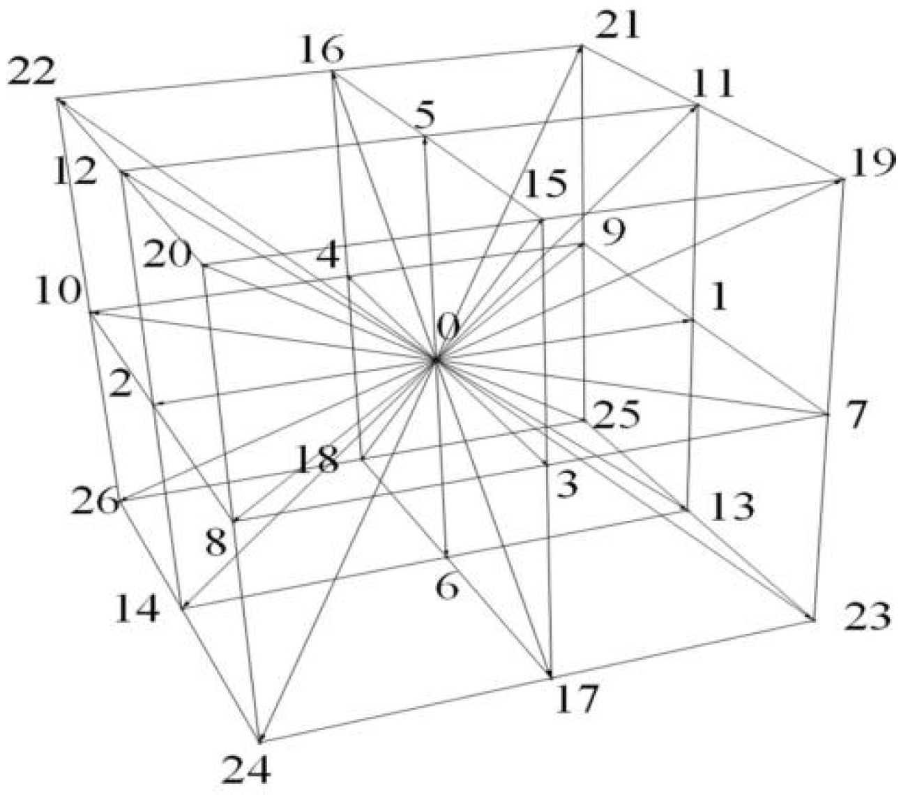
We adopt the D3Q27 model, where each lattice point has 26 neighboring lattice points, and the particles exist only on the points and can only be stationary or move to the neighboring points, as shown in Figure 1 [39]:

Figure 1.
D3Q27 model diagram.
The discrete velocity weights are shown in Table 1.

Table 1.
Discrete velocity weights .
In the discrete velocity DdQb scheme, a Taylor expansion of the local fluid velocity u is performed as shown in the following Equation (8):
2.2. LBM-VOF-LES Model
Common LBM multicomponent multiphase flow models include the Shan–Chen pseudopotential model, free energy model, and R-K model (color gradient model). However, these models do not have the capability of solving problems with large density ratios (density ratio >1000) [40]. In this paper, a single-phase free surface model (LBM-single-phase model, LB-SP model) is introduced into the LB-SP model by combining the VOF method and the surface tension model to obtain the combined LBM-VOF-LES model [41].
The VOF (Volume of Fluid) model fundamentally tracks and characterizes the interfaces between different phases. In this model, each computational grid cell is assigned a volume fraction that indicates the proportion of the cell’s volume occupied by either the liquid or gas phase. A volume fraction value of 0 signifies that the cell is completely filled with the gas phase, while a value of 1 indicates that it is entirely occupied by the liquid phase. Intermediate values between 0 and 1 represent regions where the liquid and gas phases coexist, reflecting the presence of a mixed phase [42,43,44,45].
In the current research methodology adopted by most researchers, the relaxation time in the proposed LBM model is replaced by the total relaxation time consisting of the single relaxation time and the eddy relaxation time [46], which can be expressed as follows:
where τsgs is the vortex relaxation time with respect to the turbulent eddy viscosity vt, τ is the single relaxation time with respect to the molecular viscosity υ, τe is the total relaxation time. The vortex relaxation time can be written as the following [47]:
To streamline the investigation in this study, we integrate the conventional Smagorinsky subgrid-scale model into the LBM. According to the LES theory, the turbulent eddy viscosity consists of the dynamical viscosity υ and eddy viscosity υt, respectively, which can be expressed as follows [48]:
At high temperatures, the physical properties of fluids change with temperature, and their dynamic viscosity is usually a function of temperature. υt was determined as follows:
where Smagorinsky’s constant Cs is 0.18, ij is the strain rate tensor [49]:
This is a function of the non-equilibrium momentum flux tensor after the Chapman–Enskog expansion. Combining Equations (12) and (13) in an equally spaced lattice , the total relaxation time was obtained as the following:
where .
Meanwhile, according to the LBM theory, the total viscosity υtotal is calculated as the following:
Finally, coupling the Smagorinsky model with the LB equation yields an equivalent relaxation time for the combined LBM-LES model, which can be expressed as the following:
2.3. Coupled Heat-Fluid-Solid Solution Flow
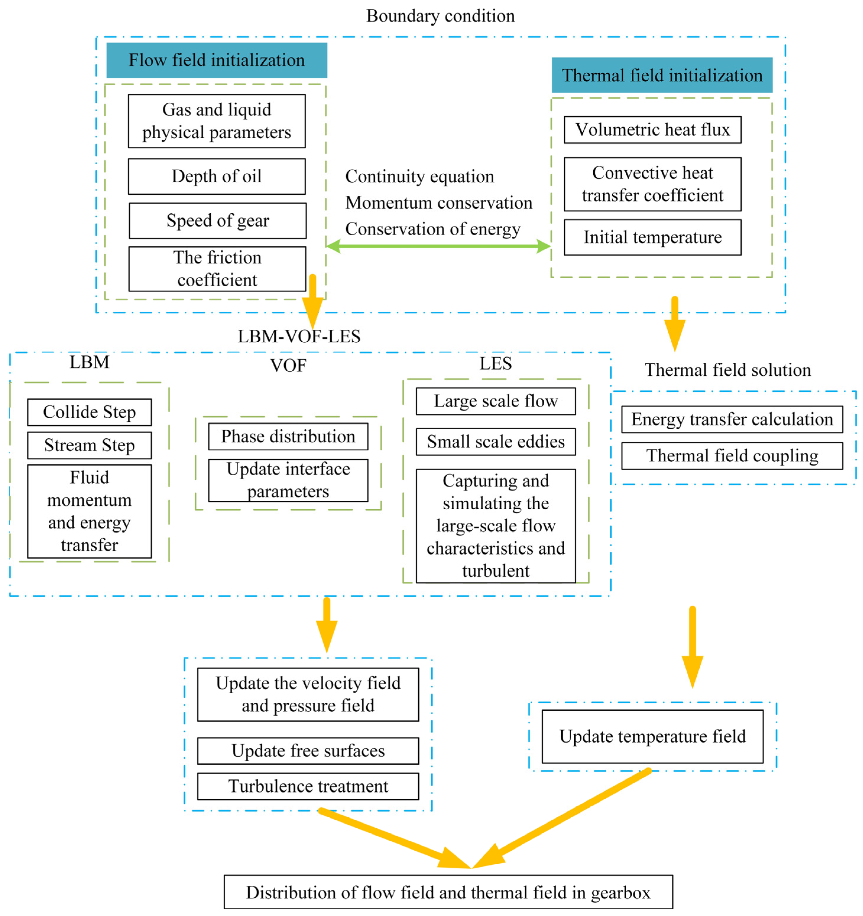
As shown in Figure 2, the strategy for solving a coupled heat-fluid-solid solution in a gearbox involves several key steps. First, it is essential to establish the boundary conditions and initialize both the flow and thermal fields with relevant parameters, including physical properties, oil depth, gear speed, heat flux, heat transfer coefficient, and initial temperature [50]. The flow field solution employs the Lattice Boltzmann method (LBM) for collision and streaming steps, the volume of fluid (VOF) method for phase distribution and interface updates, and a Large Eddy Simulation (LES) for managing large-scale flows and small-scale eddies [51,52,53,54]. Concurrently, the thermal field solution involves treating the gears as volumetric heat sources within the solid domain, and solving the energy transfer equations through thermal conduction, convection, and convective heat exchange at fluid-solid interfaces to update the temperature field [55,56,57]. In the thermal analysis of the gearbox housing, the heat flux on the outer surface of the fluid domain, determined after achieving thermal equilibrium within the gearbox, is applied as a heat source to the inner walls of the housing. Heat transfer occurs through thermal conduction and convective heat exchange [58,59,60]. The fluid and solid energy equations are solved iteratively, ensuring heat flux transfer between the fluid and solid until convergence is achieved [61,62,63,64,65]. The process is repeated, updating both the flow and thermal fields, until a comprehensive distribution of these fields within the gearbox is achieved. This provides a detailed analysis of the interactions among heat, fluid, and solid phases.
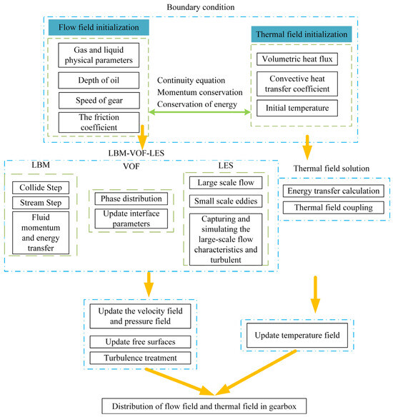
Figure 2.
Flowchart of the LBM-VOF-LES solving strategy.
3. Numerical Simulation
3.1. Physical Object Modelling
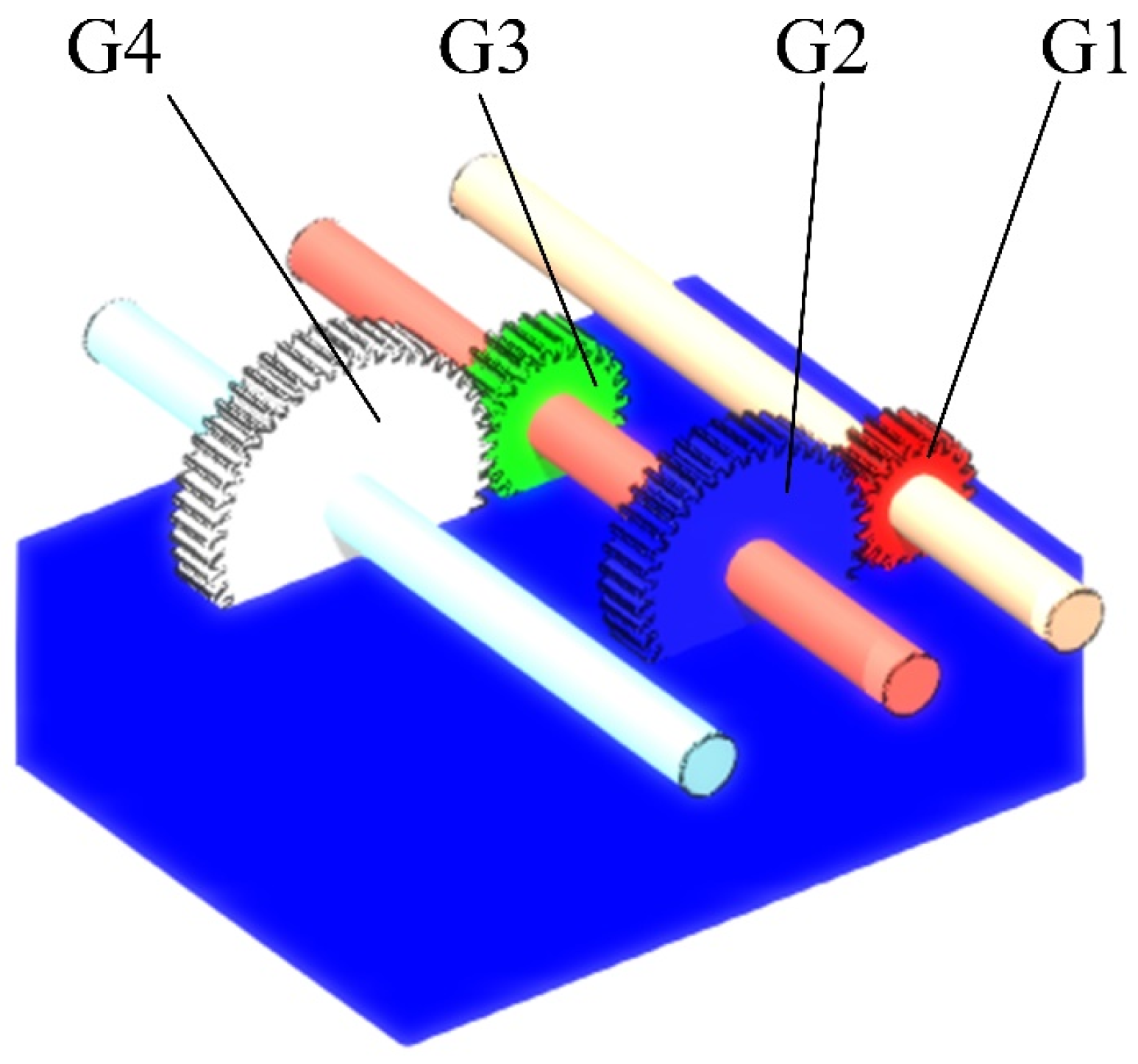
In this paper, the common two-stage cylindrical spur gear transmission is simplified, as shown in Figure 3. Among them, G1 and G2 are the high-speed stages of gears as power input shafts; G3 and G4 are the low-speed stages of gears as power output shafts, and the specific characteristic parameters are detailed in Table 2.

Figure 3.
Model of gearbox geometry.
Table 2.
Basic geometric parameters of cylindrical spur gears.
When the transmission starts to work, the pinion gear G1 of the high-speed stage starts to rotate, driving the gear G2 that meshes with it, and through the coaxial movement at the same time drives the pinion gear G3 of the low-speed stage, which in turn drives the meshed low-speed stage large gear G4. In this process, the lubricant is first introduced into the contact area of the gear pair, forming a thin but uniform film of oil that covers the gears’ tooth surfaces and bearing support surfaces. With the operation of the transmission, the friction between the gears generates a large amount of internal energy, which is converted into heat and transferred to the lubricant. The lubricant acts as a heat transfer medium, rapidly absorbing and dispersing heat throughout the lubrication system. Increasing lubricant temperature affects physical parameters such as viscosity and fluidity, which in turn affects the flow pattern and film stability of the lubricant in the gear contact area. At the same time as the temperature rises, the lubricant forms a dynamic thermal equilibrium within the system, ensuring that the lubricant effectively cools and lubricates the gears while stabilizing the system.
3.2. Fluid Dynamics Modeling with Initial Boundary Conditions
In simulating the fluid motion of a gearbox, it is challenging to construct an appropriate mesh model. Conventional computational fluid dynamics (CFD) softwares require a large number of meshes, and the mesh delineation and quality have a great influence on the simulation results. The quality and scale of the meshing process are critical in determining both the accuracy and efficiency of numerical calculations. However, due to the complexity of 3D models, achieving a reasonable meshing is often challenging. XFlow 2022 represents a cutting-edge generation of CFD software, facilitating multi-scale spatial simulations through octree-based D3Q27 grid technology and utilizing the volume method to compute fluid distribution at the grid’s center of gravity. It achieves seamless transitions in fluid dynamics across various grid levels by re-imaging cells.
The preprocessor of XFlow is capable of automatically generating an initial octree lattice structure based on the input geometry, user-specified lattice resolution, and far-field resolution. Users can also customize specific regions (e.g., spheres, boxes, cylinders, etc.) and refine these regions. The system uses a hierarchically organized multi-scale space, with the spatial and temporal scales of each level reduced by half compared to the previous one, to construct an efficient octree lattice layout. This design is particularly effective because it allows a constant ratio of x/t to be maintained throughout the fluid domain, favoring local time-stepping methods. XFlow adopts the local time-step technique so that each lattice can have the appropriate time-step according to its characteristics. Compared with the traditional finite-volume method that adopts the global time step, this method is more efficient in dealing with geometrical meshes with multiple cell sizes, which optimizes the simulation process.
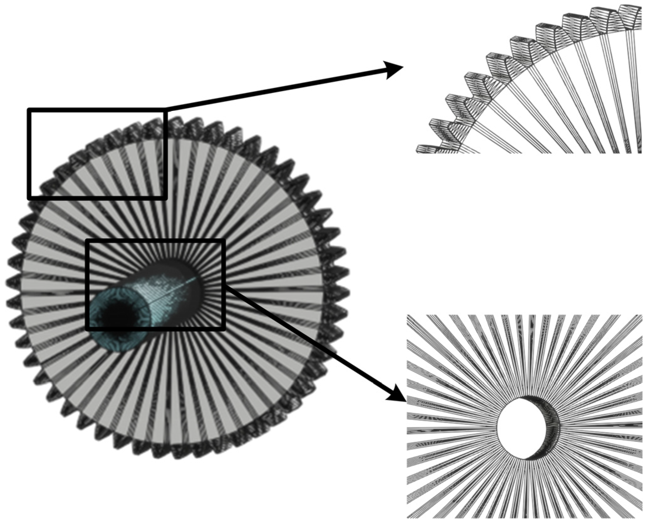
In this study, the meshing of gears and shafts is mainly structured, consisting of regular tetrahedral elements. The meshing of the shafts is more or less uniformly distributed. According to the Stokes adhesion condition, a no-slip condition exists for the fluid particles at the walls and the tangential velocity of the fluid is the same as that of the gear. There is a large pressure gradient distribution at the wall during rotation. To reduce the influence of this condition on the solution’s accuracy, the mesh is encrypted near the gear teeth and at the boundary, as shown in Figure 4.
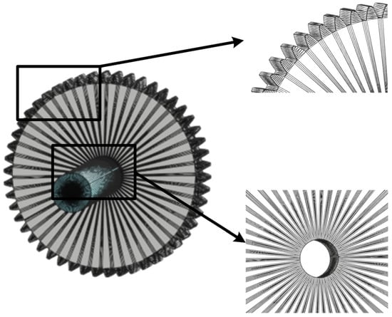
Figure 4.
Gear meshing.
The fluid motion in the enclosed space during gearing is investigated by dividing the model into three interfaces: lubricating oil, air, and gear. The depth of the oil body is set, and the rest of the area is in the gas phase. Set the initial velocity and gravitational acceleration of the fluid acting over the entire area of the flow field and the initial speed of rotation of the gears. The fundamental parameters of the fluid medium and gear material are listed in Table 3, while initial boundary conditions for the dynamic model are detailed in Table 4. The viscosity of the lubricant in question is fitted using a Walther model, based on the viscosity at 40 °C and 100 °C. The Walther model describes the relationship between the viscosity and temperature of a lubricant and is particularly applicable to mineral and synthetic lubricants. The model expresses the relationship between viscosity and temperature in logarithmic form. The advantage of this model is that it provides a better description of the change in viscosity of lubricants over a wide range of temperatures, especially in industrial and mechanical applications, and helps to optimize the selection and use of lubricants. This model can be expressed using the following equation:
where C = 0.7 and T0 = 273.15K, ν is the dynamic viscosity, and T is the absolute temperature.
Table 3.
Basic parameters of each material.
Table 4.
Boundary conditions for the hydrodynamic model.
3.3. Grid Independence Verification
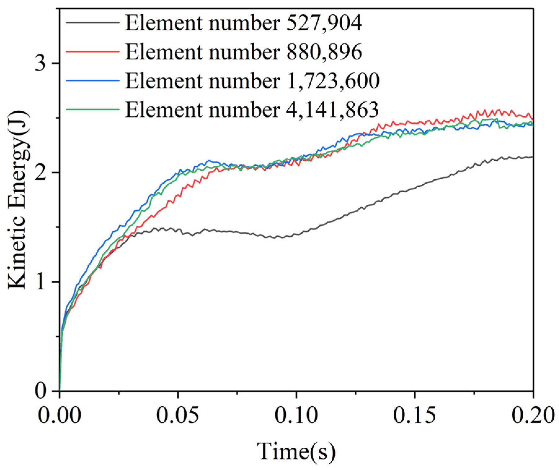
The number of grids plays a crucial role in numerical computations. Too many grids can improve computational accuracy but significantly increase computation time and resource consumption, leading to reduced efficiency. On the other hand, too few grids may enhance computational efficiency but could result in insufficient accuracy, failing to capture complex physical phenomena. To ensure the reliability of the simulation results, a mesh independence verification should be conducted. Turbulence intensity is chosen as the basis for grid independence verification because it effectively reflects the turbulent characteristics of the flow field, particularly fluctuations and instability, and is highly influenced by grid resolution. By comparing the variation in turbulence intensity across different grids, the convergence and physical accuracy of the numerical simulation can be ensured. The variation in turbulent kinetic energy at the gear intersection area under different grid resolutions is shown in Figure 5. In the early stages of time variation, turbulence intensity increases rapidly and gradually stabilizes over time. By comparing the results for different grid resolutions, we found that when the grid count was 527,904, the error in the turbulence kinetic energy was relatively large. As the grid resolution increased, the turbulence kinetic energy gradually stabilized. Further calculations showed that when the grid count was 1,723,600, the turbulence kinetic energy error compared to a grid count of 4,141,863 was less than 5%, which meets the required solution accuracy while ensuring computational efficiency. Therefore, to achieve a good balance between accuracy and efficiency, a grid count of 1,723,600 should be chosen for a gearbox simulation study.
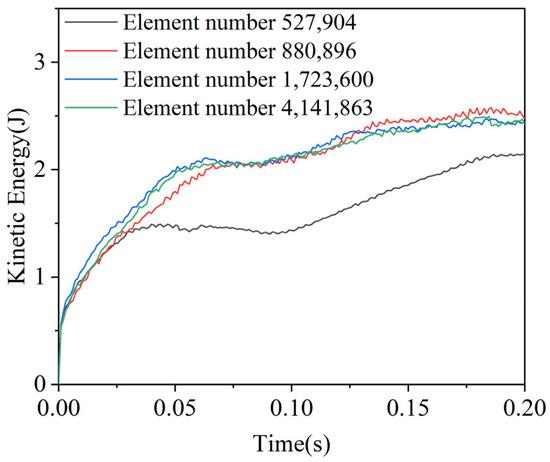
Figure 5.
Grid independence verification.
4. Results and Discussion
4.1. Analysis of Fluid Distribution
Figure 6 gives the fluid distribution within the gearbox at various moments during the process of 0~0.2 s; the oil is rapidly agitated by the swiftly rotating gears. Under the influence of viscous forces, the oil gradually forms a film between the gear teeth and on their surfaces, rotating in unison with the gears and being ejected into the air, thereby creating an oil ligament. By 0.2 s, the internal flow field of the gearbox reaches a relatively stable state. The oil film develops between the teeth and on the tooth surfaces due to viscous forces. The results indicate that a significant volume of lubricant is displaced in the gears located on the left and right sides of the gearbox, as well as beneath the gear meshing area. Despite the pinion’s higher rotational speed, the larger gear exerts a more pronounced rotational effect, displacing a greater volume of oil toward the left wall of the gearbox. In contrast, the pinion pushes a relatively smaller amount of oil toward the right wall. Consequently, the spin effect is more influenced by the diameter of the gear tip than by its rotational speed. As expected, the rotational effect increases with higher gear speeds. As the gears rotate, the lubricant circulates within the gearbox, transferring heat to the gearbox walls through convective heat transfer. The gears serve as a heat source, transferring heat to the surrounding lubricant and gearbox structure via conduction. Due to centrifugal forces, oil droplets break apart into numerous small particles, creating an oil mist in the engagement area of the gearbox. This oil mist enhances the mixing of the lubricant with air, thereby improving the efficiency of convective heat transfer. It was observed that as the gear speed increased, the air fraction in the lubricant also increased, further facilitating heat transfer. Ultimately, through heat conduction and convective heat transfer, the temperature field within the gearbox gradually stabilizes, ensuring the normal operation of the gearbox.
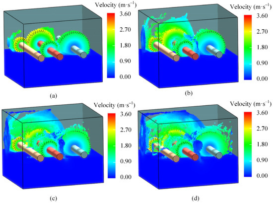
Figure 6.
Fluid distribution in the gearbox. (a) t = 0.01 s; (b) t = 0.1 s; (c) t = 0.15 s; (d) t = 0.2 s.
The results show that during the gear rotation process, the lubricating oil forms a lubrication film between the gear surfaces, reducing friction and preventing wear. Centrifugal force causes the lubricating oil to be sprayed into an oil mist, enhancing the mixing of the oil with air, thereby improving heat transfer efficiency. Eventually, through conduction and convection, the temperature field gradually stabilizes.
As shown in Figure 7, with the rotation of the tooth’s surface, the oil gradually enters the gear’s meshing area, thus having a lubricating effect. The fluid circulates the gear at a high velocity, exhibiting distinct low-speed and high-speed zones. From Figure 6d, it can be seen that the fluid velocity in the high-speed gear meshing region peaks at 3.270 m/s. This is attributed to gear rotation. Fluid movement in this unstable state exhibits complex and variable flow characteristics. An analysis of the vortex distribution within the gearbox reveals that vortices are primarily concentrated in the gear meshing areas, as shown in Figure 7. These regions generate significant eddy currents due to gear interaction and the strong shear effect induced by high rotational speed. Especially in the vicinity of the large gear; in the vicinity of the large gear, vortices are more pronounced due to the increased lubricant flow driven by the gear’s rotation. This enhances localized vortices and improves fluid mixing, thereby achieving more uniform heat dissipation. Additionally, significant vortex distributions were observed near the top and side walls of the gearbox, which were attributed to oil particles being pushed into these regions. The presence of high vortex regions indicates complex flow dynamics, but it also enhances fluid mixing, positively impacting thermal efficiency and extending the gearbox’s service life. The results show that the flow field distribution near the high-speed gear is more complex, with more pronounced turbulent characteristics, and a distinct vortex distribution forming at the edge of the gear.
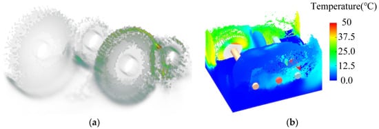
Figure 7.
Cloud diagram of steady state of gears. (a) Volume field vorticity. (b) Temperature.
As shown in Figure 7b, a distinct correlation exists between the spatial heterogeneity of the thermodynamic parameters and vortex dynamics within the gear’s meshing zones. Notably, the meshing center of the high-speed large gear exhibits significantly elevated temperatures compared to the low-speed stage, where regions of high vorticity magnitude demonstrate remarkable spatial overlap with thermal concentration areas. This phenomenon aligns fundamentally with the vortex kinetic energy dissipation theory in rotating machinery systems: when lubricating media traverse the gear pair clearance, intense shear layers generated by the relative motion of tooth surfaces induce turbulent mixing. Consequently, the vortex structures dominate the localized temperature rise mechanism through the conversion of mechanical energy into thermal energy—a process directly resulting from viscous dissipation.
4.2. Effects of RPM and Temperature on Fluid Flow Behavior in Gearboxes
In gearboxes, the flow behavior of the lubricant is closely related to both speed and temperature, and this relationship significantly affects lubrication, heat dissipation, and transmission efficiency. Rotational speed critically influences oil film formation and the distribution of lubricant flow under operating conditions. Uneven lubricant distribution or ruptured oil films can substantially reduce lubrication effectiveness. Furthermore, variations in temperature alter the physical properties of the lubricant, particularly its viscosity, thereby impacting its lubrication and heat dissipation capabilities. Consequently, gear temperature and speed are essential factors for studying the effects of these variables on fluid behavior during gearbox lubrication. To gain a deeper understanding of the lubricant flow behavior within the gearbox under various operating conditions, we established six distinct scenarios by systematically altering the gear’s temperature and rotational speed. The detailed configurations for these conditions are provided in Table 5. We set up two rotational speeds to explore the flow lubrication behavior of the lubricant at high and low rotational speeds to compare and analyze the flow lubrication behavior of the lubricant at different rotational speeds. Meanwhile, the viscosity of the lubricant is greatly affected by temperature. Therefore, three different temperatures were set to study the effect of temperature on the flow lubrication behavior of the lubricant. Analyzing these conditions allows for a deeper understanding of lubricant behavior at varying temperatures and speeds, and its impact on gearbox performance.
Table 5.
Working condition settings.
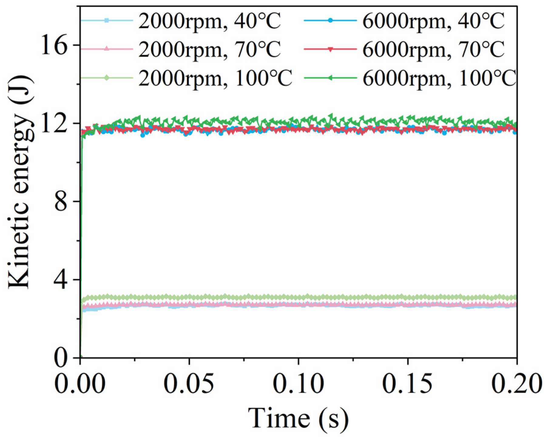
When ambient temperatures vary, the viscosity of the lubricant significantly decreases due to the temperature rise, leading to notable changes in oil flow behavior and also affecting gear stirring losses. This type of loss is generated by the agitation of the lubricant as the gears rotate, which increases the system’s energy consumption. To further analyze the fluid behavior within the gearbox, we obtained the total kinetic energy distribution of the lubricant under various operating conditions, as illustrated in Figure 8. At a lower speed of n = 2000 rpm, because the circumferential speed of the gear is relatively low, causing the gear-driven lubricant to adhere to the meshing surface and rotate in unison with the gear. This results in relatively low stirring losses. However, at n = 6000 rpm, the increased centrifugal force at the pinion tooth tip, combined with the heightened momentum of the oil particles, intensifies the stirring action, leading to increased stirring losses and the formation of fine oil channels instead of simple oil belts. At high speeds, both the oil velocity distribution and stirring losses increase, as illustrated in Figure 9 for various operating temperatures. At this stage, the greater relative motion between the gear and bearing surfaces enables the lubricant to be more effectively squeezed into frictional interfaces, forming a stable oil film that provides efficient lubrication while reducing wear and friction. However, this may also result in increased stirring losses. Furthermore, during continuous operation, the temperature of the lubricant within the gearbox rises significantly, leading to a reduction in its dynamic viscosity and the formation of extensive oil zones, which further impact stirring losses. Oil traces ejected by the pinion can travel considerable distances, with some reaching the gearbox’s top cover. In the low-speed shaft gear meshing area, under high-temperature operating conditions (T = 100 °C), the viscosity of the lubricant is significantly diminished, and shear resistance is reduced, resulting in increased stirring losses. Compared to low-temperature conditions, the lubricant at elevated temperatures spreads more widely, forming broader oil belts. As the temperature rises, the flow rate of the lubricant accelerates, and the kinetic energy correspondingly increases; however, this may also lead to heightened stirring losses. A lubricant with higher kinetic energy covers surfaces more effectively; nevertheless, excessive kinetic energy can cause splashing and film rupture, thereby increasing stirring losses and adversely affecting lubrication.
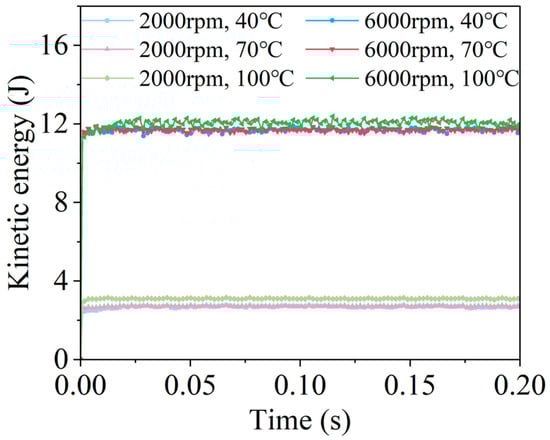
Figure 8.
Variation of total kinetic energy of fluid under different working conditions.
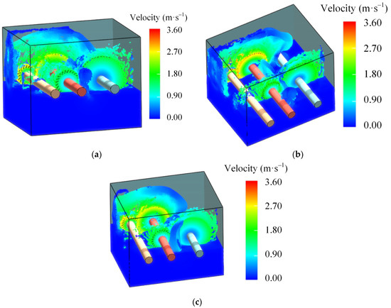
Figure 9.
Cloud diagram of oil velocity distribution at different temperatures and high speeds. (a) T = 100 °C. (b) T = 70 °C. (c) T = 40 °C.
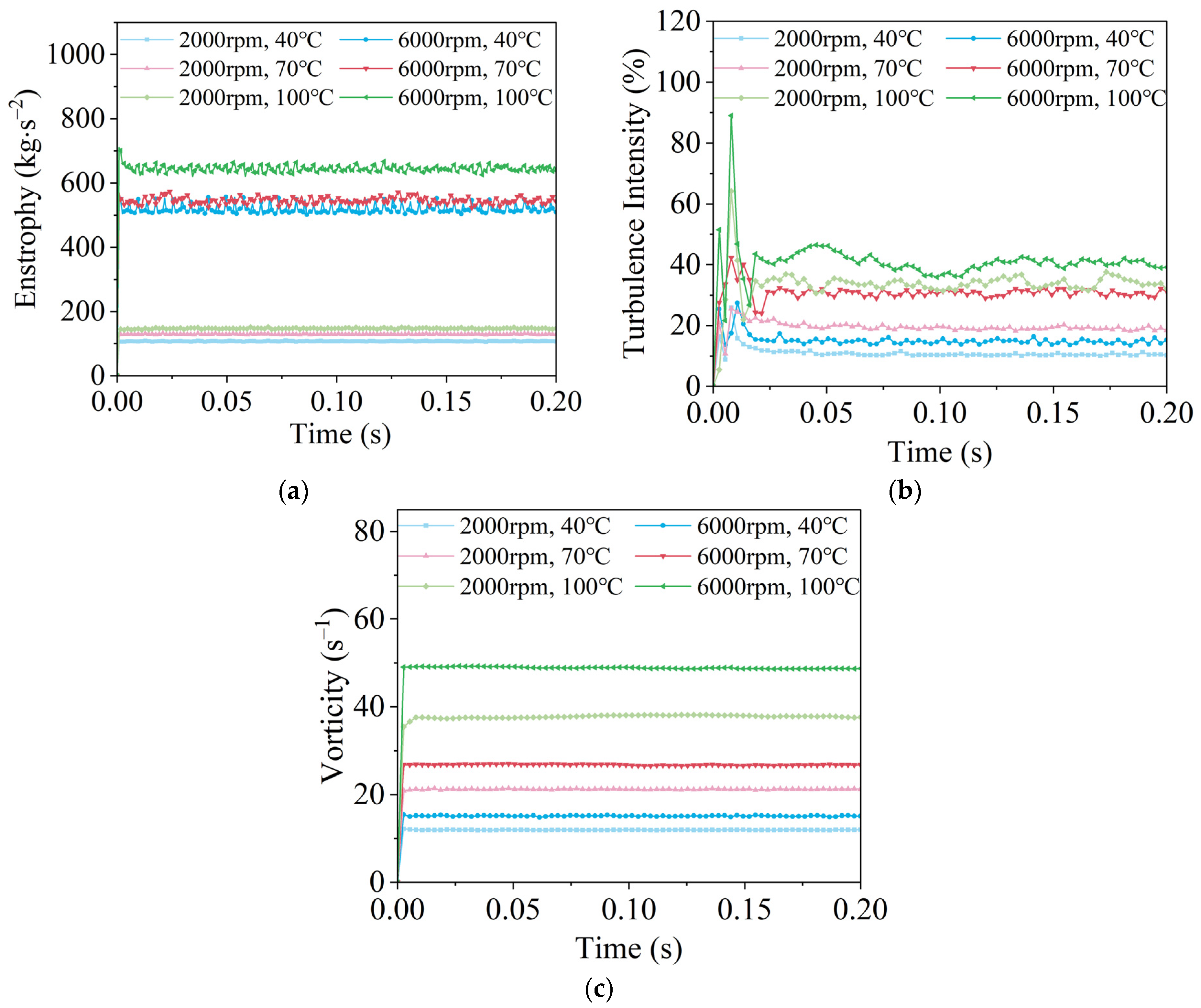
In this case, both the vortex energy and vortex volume remain relatively constant as the gear quickly reaches a steady state after starting up. Turbulence intensity rises rapidly as the gears rotate, peaks, and then declines sharply before stabilizing. During the initial phase of the gear startup, the fluid is significantly disturbed by the gear’s movement, leading to dramatic changes in fluid velocity and a rapid increase in turbulence intensity. This phenomenon is attributed to the high turbulence intensity generated by the strong shear forces and velocity gradients present in the initial phase. The reduction in dynamic viscosity decreases internal friction and enhances fluidity. Consequently, the lubricant flows more swiftly and actively within the gearbox, resulting in increased flow irregularities and turbulence, which is evident in the rise of turbulence intensity and eddy volume. Over time, the initial strong perturbations are gradually dissipated by the fluid’s viscosity and flow structure, causing the turbulence intensity to reach its peak. At this time, the velocity fluctuations within the fluid are maximized. Following this peak, the turbulent structures in the fluid gradually dissipate, and the turbulent energy is converted into heat and other forms of energy, leading to a decrease in turbulence intensity. This process is typically accompanied by a stabilization of the fluid flow, a reduction in the flow velocity gradient, and ultimately a stabilization of turbulence intensity at a lower level. As illustrated in Figure 10b, as the temperature increases and the rotational speed rises, the peak turbulence intensity that can be achieved is higher, although the time at which this peak occurs is later. This phenomenon can be attributed to the fact that, with a rising temperature and increased rotational speed, the fluid requires more time to accumulate sufficient energy to attain a higher peak turbulence intensity. Concurrently, more complex turbulent structures form within the fluid, further delaying the time to reach peak turbulence. In contrast, vorticity, which refers to the degree of rotational motion in a fluid, and vortex-simulated energy, representing the sum of the squares of the vortices, can be interpreted as the energy density of rotational motion in a fluid. Given that the motion of the gears is steady, the vorticity in the fluid will stabilize quickly and remain relatively constant over time.
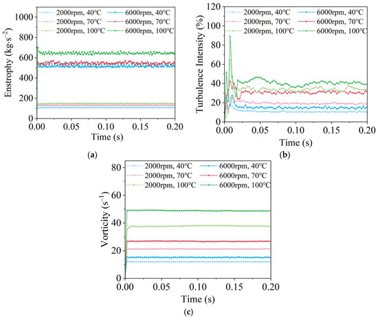
Figure 10.
Distribution of turbulence intensity and eddy volume under different working conditions. (a) Enstrophy. (b) Turbulence intensity. (c) Vorticity.
4.3. The Influence of RPM and Temperature on High-Speed Class Area Fluids
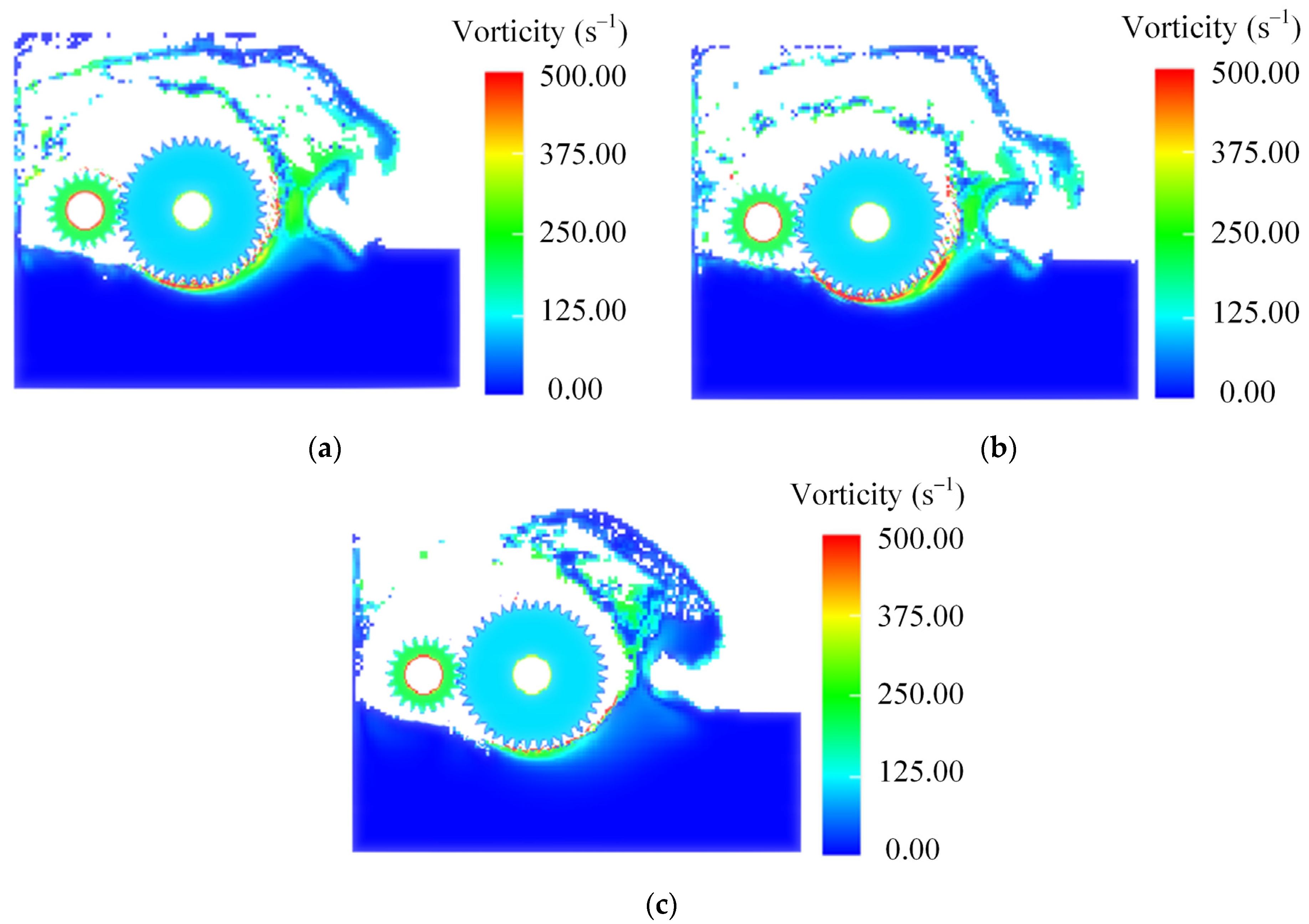
To further analyze the lubrication and heat dissipation behavior, the distribution of eddy currents in the meshing region of the high-speed driveshaft gears is examined under varying temperatures and high-speed conditions (n = 6000 rpm), as illustrated in Figure 11. Our findings indicate that the eddy current values at the edges of the high-speed shaft gears are elevated across different ambient temperatures, particularly in the areas in contact with other gears. This phenomenon is attributed to the significant relative velocity differences and shear forces generated by the meshing process, which result in more intense local rotation and fluid flow. Conversely, in the regions where the gears make contact, the edges of the high-speed shaft gears exhibit lower vorticity values compared to other areas. This can be explained by the fact that during the operation of the high-speed shaft gears, G1 and G2 rotate in phase with one another, leading to a reduced vortex distribution in the meshing region. Additionally, the distribution of vorticity on the right side of the gear is greater due to the clockwise rotation of the gear on that side, which facilitates the expulsion of oil. The presence of significant viscous resistance drives the oil between the teeth and at the edge of the gear to undergo a coordinated rotary motion. However, as the rotation continues, the viscous resistance is unable to provide the necessary centripetal force to keep the oil rotating in unison. Consequently, the oil begins to be expelled due to inertial forces. The vorticity distribution around the high-speed shaft gear is relatively uniform but decreases with increasing distance from the gear surface. This observation indicates that the fluid is agitated in the vicinity of the gear, while the rotational effect diminishes with distance. As the gear rotates, a significant amount of fluid is ejected into the air and flows toward the top of the gearbox, resulting in a pronounced vorticity distribution in that region. However, as the temperature decreases and the viscosity of the lubricant increases, the overall vorticity of the gears diminishes. This phenomenon occurs because an increase in viscosity renders the lubricant thicker, thereby increasing resistance to flow. Higher viscosity lubricants generate greater resistance during gear meshing, which inhibits rapid fluid flow and the formation of turbulence. Simultaneously, high-viscosity lubricants create a thicker oil film on the gear’s surface, allowing for a more uniform coverage of the gear’s surface and a reduction in localized variations in flow velocity. This, in turn, contributes to a more uniform overall flow field.

Figure 11.
Cloud view of vortex distribution at different temperatures at high-speed level at n = 6000 rpm. (a) T = 100 °C. (b) T = 70 °C. (c) T = 40 °C.
To further investigate the prevalence of this phenomenon, we analyzed the variation of lubricant eddy currents in the regional cross-section of high-speed class gears at different temperatures and lower rotational speeds (n = 2000 rpm), as illustrated in Figure 12. We observed that the overall eddy currents were smaller at lower rotational speeds compared to high-speed conditions. As the temperature increased, the lubricant vortices intensified both at the gear’s surface in contact with the lubricant and at the injection point. This intensification is attributed to a reduction in viscous drag and an increase in the velocity of the lubricant as it moves away from the gear. In summary, during both high- and low-speed operations, a decrease in temperature and an increase in the viscosity of the lubricant lead to greater resistance to flow and increased viscous dissipation. This phenomenon inhibits the formation and development of turbulence, resulting in reduced vorticity and a more uniform vortex distribution. Furthermore, high-speed operations, which possess greater kinetic energy, allow the lubricant to form a thinner and faster oil film on the surfaces of the high-speed gears. This condition promotes the formation of turbulence and an increase in eddies. The rise in kinetic energy contributes to the development of more turbulent structures at the gear surface and the injection point, thereby enhancing the local strength of the eddies.
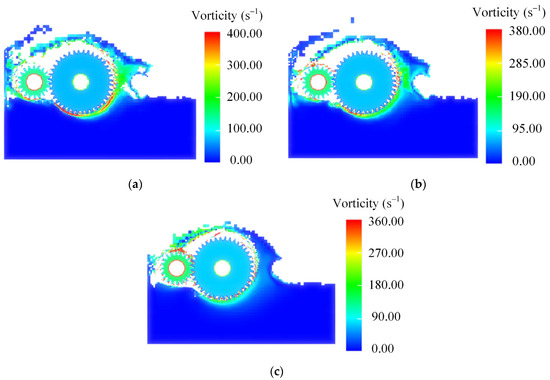
Figure 12.
Cloud view of vortex distribution at different temperatures at high-speed level at n = 2000 rpm. (a) T = 100 °C. (b) T = 70 °C. (c) T = 40 °C.
These results indicate that vortices are primarily caused by the shear forces and relative velocity differences generated during the gear meshing process. When the gears rotate rapidly, the friction and relative motion between the gear’s teeth generate strong shear forces, driving the lubricant to form rotational flow on the gear’s surface and between the teeth. Under high-speed operation and high-temperature conditions, vortices and turbulence become more significant. While this helps with the flow of the lubricant and reduces friction, it also increases stirring losses and energy consumption.
4.4. The Influence of RPM and Temperature on Fluids in the Low-Speed Class Area
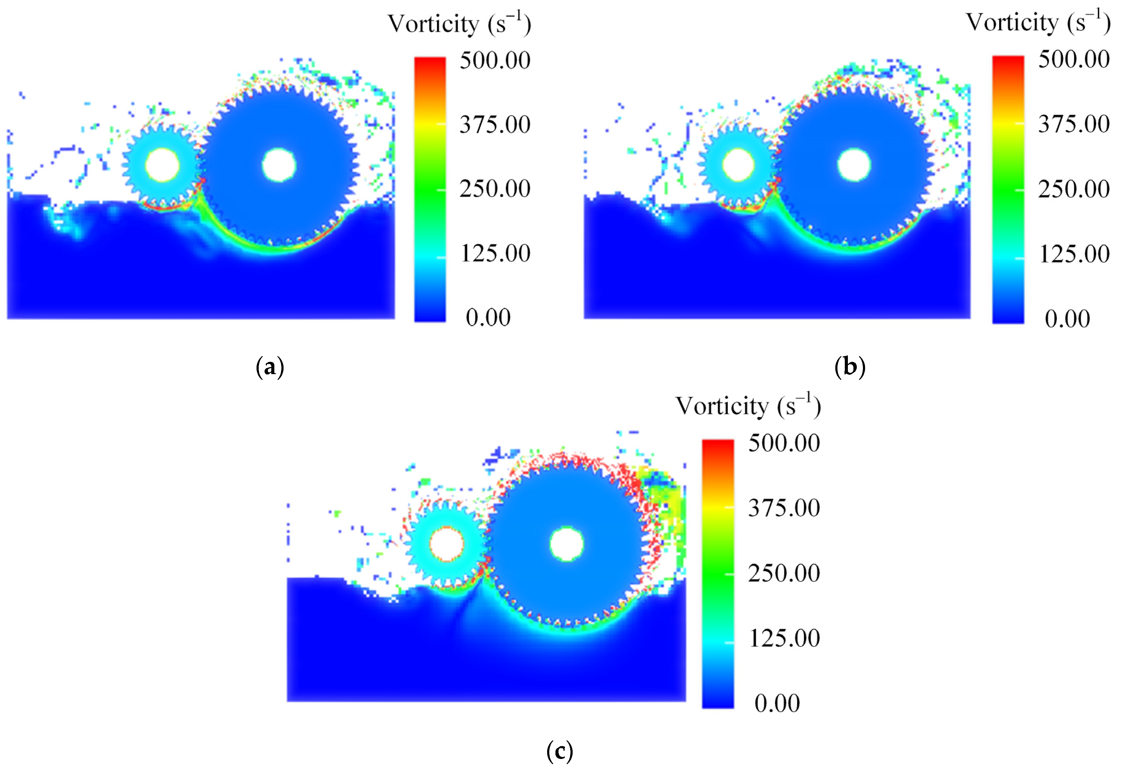
During gear operation, the higher rotational speed of the high-speed stage gear set results in increased overall fluid velocity, turbulence intensity, and vorticity compared to the low-speed stage gear set. However, the distribution and motion behavior of the fluid in the low-speed gear set region during high-speed operation can significantly affect the efficiency and service life of the gears. We analyzed the vorticity distribution of the oil in the low-speed gear section under various operating conditions, as illustrated in Figure 12. The temperature distribution of the oil in the low-speed gear section at different rotational speeds is presented in Figure 13. The oil vortex is less pronounced in the low-speed stage gear region compared to the high-speed shaft gear. However, in the gear meshing region, the opposing rotation of the gears generates substantial shear and stirring forces, resulting in a greater vorticity distribution. In the meshing region, gears G3 and G4 work together to drive the oil upward toward the gears. On the left side, G3 propels the oil against the left wall due to inertial forces, while on the right side, G4 also directs the oil toward the left wall. A comparison of the vortices generated by G3 and G4 reveals that G4 produces a significantly larger number of vortices than G3. This difference can be attributed to the fact that, although both gears have the same linear velocity, G4 has a larger gear radius than G3, resulting in a more pronounced flinging effect on the surface of the gears. Consequently, the lubricant is more likely to form and sustain large vortex structures under the influence of G4. As the temperature decreases, the increased viscous resistance leads to a diminishing flinging effect at the same rotational speed. This is evident in the observation that, as the temperature drops, the oil achieves a lower throw height. At a temperature of 40 °C, a substantial amount of oil surrounding the G4 gear is unable to be flung into the air; instead, it is directed by the gear onto the right wall, creating greater turbulence.

Figure 13.
Cloud diagram of vortex volume distribution at low-speed level for different temperatures at n = 6000 rpm. (a) T = 100 °C. (b) T = 70 °C. (c) T = 40 °C.
With a reduction in rotational speed, the low-speed gear experiences a decrease in rotational velocity, leading to a minimal oil injection effect on mixing. Consequently, the resulting eddy currents are also diminished, and the oil flow and distribution remain relatively smooth. Even at low rotational speeds, the gear meshing zones continue to generate significant shear forces and eddy currents due to their relative motion. As the gears rotate, each zone comes into contact with oil for lubrication and cooling. Simultaneously, the oil flinging effect around the G3 and G4 gears behaves similarly as the temperature decreases. As the temperature drops, the flinging effect becomes less pronounced. For G4, under the working conditions of T = 40 °C and n = 2000 rpm, the vortex distribution of the oil around the gear is nearly imperceptible, with only a portion of the oil adhering to the surface of G4. This phenomenon is also attributed to increased viscous resistance, which thickens the oil film, resulting in smoother fluid dynamics.
The simulation results indicate significant differences in the distribution and dynamic characteristics of the oil within the gearbox at varying speeds and temperatures. At high rotational speeds (n = 6000 rpm), as illustrated in Figure 14, both the velocity and turbulence intensity of the oil increase, particularly in the gear–oil contact region, resulting in larger eddy currents. As the temperature rises, the viscosity of the oil decreases, leading to a rapid increase in turbulence intensity and eddy volume. This reduction in viscosity results in a thinner oil film, which increases the contact area with the air, thereby enhancing lubrication efficiency and significantly improving convective heat dissipation. Conversely, at lower speeds (n = 2000 rpm), the oil flow is smoother with reduced vorticity; however, notable vorticity still occurs in the mesh area. The oil exhibits a more homogeneous and even laminar flow, with a thicker oil film compared to higher speeds. The higher viscosity at lower temperatures hampers the oil’s ability to provide adequate lubrication. In contrast, at elevated temperatures, the kinetic energy and vorticity of the oil increase, enhancing both lubrication and heat dissipation performance. The high vorticity generated in the gear meshing zone facilitates fluid mixing and heat dissipation, with significant vorticity distribution observed on the top and side walls of the gearbox.
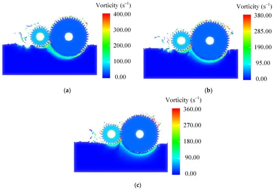
Figure 14.
Cloud plot of vortex volume distribution at low-speed level for different temperatures at n = 2000rpm. (a) T = 100 °C. (b) T = 70 °C. (c) T = 40 °C.
The fluid lubrication’s behavior between the high-speed shaft (G1 and G2) and the low-speed shaft (G3 and G4) differs significantly due to variations in rotation direction and rotational speed. In the case of G1 and G2, the inward rotation of the two meshing regions prevents the formation of large vortices. Instead, a substantial amount of oil is rolled up on both sides, which facilitates lubrication and heat dissipation. Conversely, near the low-speed shaft, a large vortex forms in the meshing area. Here, the oil is rolled up and ejected to the sides. However, because the rotational speed of the low-speed shaft is considerably lower than that of the high-speed shaft, less oil is ejected toward the side walls. Instead, the oil falls back onto the gears, aiding in the lubrication of the gear drive.
This study indicates that both rotational speed and temperature significantly affect the fluid behavior in the low-speed gear region. At high speeds, the oil exhibits stronger vortices and turbulence, which aids in lubrication and heat dissipation but also increases energy consumption and stirring losses. At low speeds, the flow of oil is smoother, resulting in a poorer lubrication performance. Under low-temperature conditions, the viscosity of the oil increases, but its lubrication performance decreases. Therefore, the design of the gear system should select appropriate an oil temperature and speed based on actual operating conditions to balance lubrication effectiveness and energy consumption.
5. Conclusions
The study of gear lubrication dynamics and heat transfer characteristics is crucial for improving the transmission efficiency and performance of automotive gears. This research, based on the LBM-LES coupling model and using the D3Q27 three-dimensional space model to describe the particle distribution function, delves into the dynamic behavior and heat transfer characteristics of lubricating oil in gear transmissions. Our research has investigated the flow field, turbulent kinetic energy, and temperature distribution transfer process of lubricating oil in a secondary gearbox under different temperatures and rotational speeds. It has drawn the following conclusions:
- (1)
- The vortices generated by gear rotation help to evenly dissipate heat. This study shows that the interaction between gears and the strong shear effects generated at high speeds create vortices. In high vortex areas, the fluid mixes more thoroughly, leading to more uniform heat dissipation.
- (2)
- Rotational speed has a significant impact on oil film formation and lubricating oil distribution. High rotational speeds enhance the kinetic energy of the lubricating oil, allowing it to better cover the lubricating surface. However, excessively high speeds can cause oil film rupture, negatively affecting lubrication performance.
- (3)
- Temperature significantly impacts lubrication performance. At low temperatures, high-viscosity oils increase resistance and reduce lubrication efficiency. As temperature rises, viscosity decreases, further affecting lubrication. Therefore, lubricants with suitable viscosity and thermal stability should be selected based on the gearbox’s working temperature range.
This study introduces a comprehensive analytical framework for the dynamics characteristics of multi-stage transmission systems. It highlights the complex effects of lubricating oil flow, temperature, and viscosity on lubrication performance and suggests strategies for optimizing gearbox design and selecting lubricants. These findings provide a scientific basis for gearbox design and lubricant development, offering valuable insights for improving the performance of gear systems in the automotive industry.
Author Contributions
Conceptualization, G.Z.; methodology, G.Z.; software, L.L.; validation, G.Z.; formal analysis, L.L.; investigation, P.X.; resources, P.X.; data curation, P.X.; writing—original draft preparation, L.L.; writing—review and editing, G.Z.; visualization, G.Z.; supervision, L.L.; project administration, G.Z.; funding acquisition, L.L. All authors have read and agreed to the published version of the manuscript.
Funding
This work was partly supported by the Zhejiang Provincial Natural Science Foundation under Grant No. LQ23E050017; Fundamental Research Funds for the Provincial Universities of Zhejiang (RF-A2024001).
Data Availability Statement
The original contributions presented in the study are included in the article, further inquiries can be directed to the corresponding author.
Conflicts of Interest
The authors declare no conflicts of interest.
References
- Tan, D.P.; Li, P.Y.; Ji, Y.X.; Wen, D.H.; Li, C. SA-ANN-based slag carry-over detection method and the embedded WME platform. IEEE Trans. Ind. Electron. 2013, 60, 4702–4713. [Google Scholar] [CrossRef]
- Xu, P.; Li, Q.H.; Wang, C.Y.; Li, L.; Tan, D.P.; Wu, H.P. Interlayer healing mechanism of multipath deposition 3D printing models and interlayer strength regulation method. J. Manuf. Process. 2025, in press. [Google Scholar]
- Hildebrand, L.; Genuin, S.; Lohner, T.; Stahl, K. Numerical analysis of the heat transfer of gears under oil dip lubrication. Tribol. Int. 2024, 195, 109652. [Google Scholar] [CrossRef]
- Liu, L.; Zhang, X.T.; Tian, X.L.; Li, X. Numerical investigation on dynamic performance of vertical hydraulic transport in deepsea mining. Appl. Ocean. Res. 2023, 130, 103443. [Google Scholar] [CrossRef]
- Tashakori-Asfestani, F. Effect of inter-particle forces on solids mixing in fluidized beds. Powder Technol. 2023, 415, 118098. [Google Scholar] [CrossRef]
- Ezure, T.; Kimura, N.; Miyakosh, H.; Kamide, H. Experimental investigation on bubble characteristics entrained by surface vortex. Nucl. Eng. Des. 2011, 241, 4575–4584. [Google Scholar] [CrossRef]
- Naderi, V.; Farsadizadeh, D.; Lin, C.; Gaskin, S. A 3D Study of an Air-Core Vortex Using HSPIV and Flow Visualization. Arab. J. Sci. Eng. 2019, 44, 8573–8584. [Google Scholar] [CrossRef]
- Wang, L.J.; Zhang, S.; Cui, T. Kinetic characteristics of a bionic screen with continuous variable amplitude from front to rear and behaviour of maize mixture on the screen. Powder Technol. 2023, 424, 118370. [Google Scholar] [CrossRef]
- Kan, K.; Zhang, Q.Y.; Xu, Z.; Zheng, Y.; Gao, Q.; Shen, L. Energy loss mechanism due to tip leakage flow of axial flow pump as turbine under various operating conditions. Energy 2022, 250, 124532. [Google Scholar] [CrossRef]
- Mulligan, S.; De, C.G.; Casserly, J.; Sherlock, R. Understanding turbulent free-surface vortex flows using a Taylor-Couette flow analogy. Sci. Rep. 2018, 8, 824. [Google Scholar] [CrossRef]
- Saleem, A.S.; Cheema, T.A.; Ahmad, S.M.; Chatta, J.A.; Akbar, B.; Park, C.W. Parametric study of single-stage gravitational water vortex turbine with cylindrical basin. Energy 2020, 200, 117464. [Google Scholar] [CrossRef]
- Miad, Y.; Marios, C.S. A novel approach for modeling the multiscale thermo-fluids of geared systems. Int. J. Heat Mass Transf. 2014, 72, 517–530. [Google Scholar]
- Gu, Y.H.; Li, L.; Zheng, G.A. Study on the dynamic characteristics of the gear lubrication flow field with baffles and optimization design strategies. Lubricants 2025, in press. [Google Scholar]
- Moshammer, T.; Mayr, F.; Kargl, K.; Honeger, C. Simulation of Oil Flow in Gear Box Housing; SAE Technical Paper; SAE: Warrendale, PA, USA, 2006. [Google Scholar]
- Korsukova, E.; Morvan, H. Preliminary cfd simulations of lubrication and heat transfer in a gearbox//Turbo Expo: Power for Land, Sea, and Air. Am. Soc. Mech. Eng. 2017, 50886, V05BT22A014. [Google Scholar]
- Lu, F.; Wang, M.; Pan, W.; Bao, H.; Ge, W. CFD-based investigation of lubrication and temperature characteristics of an intermediate gearbox with splash lubrication. Appl. Sci. 2020, 11, 352. [Google Scholar] [CrossRef]
- Li, J.; Qian, X.; Liu, C. Comparative study of different moving mesh strategies for investigating oil flow inside a gearbox. Int. J. Numer. Methods Heat Fluid Flow 2022, 32, 3504–3525. [Google Scholar] [CrossRef]
- Uerlich, R.; Koch, T.; Theising, H.; Eckstein, L. Method for thermal evaluation of automotive gearbox packages taking into account load point-dependent oil distribution. Automot. Engine Technol. 2022, 7, 245–264. [Google Scholar] [CrossRef]
- Qian, X.; Yan, W.; Chen, S.; Zhang, Y.; Luo, Y.; Liu, C. Optimization of splash lubrication in the gearbox considering heat transfer performance. Tribol. Int. 2024, 195, 109592. [Google Scholar] [CrossRef]
- Wang, Y.; Niu, W.; Wei, S.; Song, G. Influence of spin flow on lubricating oil jet—Design method of oil spray parameters to high speed spur gears. Tribol. Int. 2015, 92, 290–300. [Google Scholar] [CrossRef]
- Liu, H.; Jurkschat, T.; Lohner, T.; Stahl, K. Determination of oil distribution and churning power loss of gearboxes by finite volume CFD method. Tribol. Int. 2017, 109, 346–354. [Google Scholar] [CrossRef]
- Ouyang, T.; Mo, X.; Lu, Y.; Wang, J. CFD-vibration coupled model for predicting cavitation in gear transmissions. Int. J. Mech. Sci. 2022, 225, 107377. [Google Scholar] [CrossRef]
- Li, Q.H.; Xu, P.; Li, L.; Xu, W.X.; Tan, D.P. Investigation on the Lubrication Heat Transfer Mechanism of the Multilevel Gearbox by the Lattice Boltzmann Method. Processes 2024, 12, 381. [Google Scholar] [CrossRef]
- Su, R.A.; Gao, Z.Y.; Chen, Y.Y.; Zhang, C.Q. Large-eddy simulation of the influence of hairpin vortex on pressure coefficient of an operating horizontal axis wind turbine. Energy Convers. Manag. 2022, 267, 115864. [Google Scholar] [CrossRef]
- Liu, Z.B.; Wang, S.; Chen, Z.R. Electromechanical coupling characteristics analysis of vertical stirred mill based on ECS-MBD-DEM. Powder Technol. 2024, 433, 119245. [Google Scholar] [CrossRef]
- Deshpande, S.; Joshi, H.; Madhavan, J. Two-Way Coupled CFD Approach for Predicting Gear Temperature of Oil Jet Lubricated Transmissions. SAE Int. J. Commer. Veh. 2018, 11, 163–170. [Google Scholar] [CrossRef]
- Afra, B.; Karimnejad, S.; Delouei, A.A.; Tarokh, A. Flow control of two tandem cylinders by a highly flexible filament: Lattice spring IB-LBM. Ocean. Eng. 2022, 250, 111025. [Google Scholar] [CrossRef]
- Zheng, G.; Xu, P.; Wang, T.; Yan, Q. Study on the bubble collapse characteristics and heat transfer mechanism of the microchannel reactor. Processes 2025, 13, 281. [Google Scholar] [CrossRef]
- Li, Z.; Wang, C.Y.; Wu, J.F.; Yin, Z.C.; Tan, D.P. Numerical investigation of mesoscale multiphase mass transport mechanism in fibrous porous media. Eng. Appl. Comput. Fluid Mech. 2024, 18, 2363246. [Google Scholar] [CrossRef]
- Guo, X.M.; Yang, M.Y.; Li, F.Q.; Zhu, Z.C.; Cui, B.L. Investigation on Cryogenic Cavitation Characteristics of an Inducer Considering Thermodynamic Effects. Energies 2024, 17, 3627. [Google Scholar] [CrossRef]
- Zhang, Y.K.; Li, Z.; Li, L.; Wang, C.Y.; Wu, J.F.; Xie, Y.S.; Yin, Z.C.; Tan, D.P. Deposition Mechanism of Microscopic Impacting Droplets on Flexible Porous Substrates. Int. J. Mech. Sci. 2025, 288, 110050. [Google Scholar] [CrossRef]
- Conzalez, J.F.; Sanson, L.Z. Linear stability of monopolar vortices over isolated topography. J. Fluid Mech. 2023, 959, A23. [Google Scholar] [CrossRef]
- Chen, Y.C.; Huang, S.L.; Li, Z.Y. A bathtub vortex under the influence of a protruding cylinder in a rotating tank. J. Fluid Mech. 2013, 733, 134–157. [Google Scholar] [CrossRef]
- Javadzadegan, A.; Joshaghani, M.; Moshfegh, A.; Akbari, O.A.; Afrouzi, H.H.; Toghraie, D. Accurate meso-scale simulation of mixed convective heat transfer in a porous media for a vented square with hot elliptic obstacle: An LBM approach. Phys. A Stat. Mech. Its Appl. 2020, 537, 122439. [Google Scholar] [CrossRef]
- Sagaut, P. Toward advanced subgrid models for Lattice-Boltzmann-based Large-eddy simulation: Theoretical formulations. Comput. Math. Appl. 2010, 59, 21942199. [Google Scholar] [CrossRef]
- Wu, J.F.; Xu, P.; Li, L.; Li, Z.; Qi, H.; Wang, C.Y.; Zhang, Y.K.; Xie, Y.S.; Tan, D.P. Multiphase dynamic interfaces and abrasive transport dynamics for abrasive flow machining in shear thickening transition states. Powder Technol. 2024, 446, 120150. [Google Scholar] [CrossRef]
- Xu, W.X.; Yang, Y.; Tan, D.P. The utilization and advancement of laser ultrasound testing in the assessment of aerospace composite characteristics: A review. Chin. J. Aeronaut. 2025, in press. [Google Scholar]
- Ji, R.; Shen, Q.; Zhang, L.; Zeng, X.; Qi, H. Novel photocatalysis-assisted mechanical polishing of laser cladding cobalt-based alloy using TiO2 nanoparticles. Powder Technol. 2024, 444, 119990. [Google Scholar] [CrossRef]
- Yang, Y.; Bashir, M.; Li, C.; Michailides, C.; Wang, J. Mitigation of coupled wind-wave-earthquake responses of a 10 MW fixed-bottom offshore wind turbine. Renew Energy 2020, 157, 1171–1184. [Google Scholar] [CrossRef]
- Tan, Y.F.; Ni, Y.S.; Xu, W.X.; Xie, Y.S.; Tan, D.P. Key technologies and development trends of the soft abrasive flow finishing method. J. Zhejiang Univ.-Sci. A 2023, 24, 1043–1064. [Google Scholar] [CrossRef]
- Wang, C.Y.; Li, Z.; Hou, Y.Q.; Tan, D.P. Collision modelling approach and transient response mechanism of ring-ribbed cylindric shells for underwater vehicles. Appl. Math. Model. 2025, 141, 115923. [Google Scholar] [CrossRef]
- Yan, W.J.; Feng, Z.Q.; Yang, W.; Yuen, K.V. Bayesian inference for the dynamic properties of long-span bridges under vortex-induced vibration with Scanlan’s model and dense optical flow scheme. Mech. Syst. Signal Process 2022, 174, 109078. [Google Scholar] [CrossRef]
- Tong, W.J.; Li, L. Analysis of Flow Field and Machining Parameters in RUREMM for High-precision Micro-texture Fabrication on SS304 Surfaces. Sci. Prog. 2025, in press. [Google Scholar]
- Tan, D.P.; Tao, Y.; Zhao, J. Free sink vortex Ekman suction-extraction evolution mechanism. Acta Phys. Sin. 2016, 65, 054701. [Google Scholar]
- Deloue, A.A.; Karimnejad, S.; He, F.L. Direct Numerical Simulation of pulsating flow effect on the distribution of non-circular particles with increased levels of complexity: IB-LBM. Comput. Math. Appl. 2022, 121, 115–130. [Google Scholar]
- Chen, X.Y.; Li, Y.L.; Xu, Y.L.; Tan, H.J.; Wang, B. Evolution laws of distributed vortex-induced pressures and energy of a flat-closed-box girder via numerical simulation. Adv. Struct. Eng. 2020, 23, 2776–2788. [Google Scholar] [CrossRef]
- Zheng, G.A.; Weng, X.X.; Wang, T.; Xu, P.; Xu, W.X.; Li Lin Xu, X.F.; Tan, D.P. Piezoelectric ultrasonic coupling-based polishing of micro-tapered holes with abrasive flow. J. Zhejiang Univ.-Sci. A 2025, in press. [Google Scholar]
- Arab, A.; Javadi, M.; Anbarsooz, M.; Moghiman, M. A numerical study on the aerodynamic performance and the self-starting characteristics of a Darrieus wind turbine considering its moment of inertia. Renew. Energy 2017, 107, 298–311. [Google Scholar] [CrossRef]
- Nathena, P.; Haussmann, M.; Krause, M.I.; Adams, N.A. Adaptive filtering for the simulation of turbulent flows with lattice Boltzmann methods. Comput. Fluids 2018, 172, 510–523. [Google Scholar] [CrossRef]
- Du, X.Z.; Zhang, M.; Chang, H.; Wang, Y.; Yu, H. Micro windmill piezoelectric energy harvester based on vortex- induced vibration in tunnel. Energy 2022, 238, 121734. [Google Scholar] [CrossRef]
- Li, L.; Xu, P.; Li, Q.H.; Yin, Z.C.; Zheng, R.Y.; Wu, J.F.; Bao, J.J.; Qi, H.; Tan, D.P. Multi-field coupling mixing transfer mechanism of the microreactor and the ultrasonic control method. Powder Technol. 2025, 120731. [Google Scholar] [CrossRef]
- Wang, T.; Tan, D.P.; Hou, Y.Q.; Wang, C.Y.; Cheng, J.W.; Song, W.L. Analytical and experimental investigation of vibration response for the cracked fluid-filled thin cylindrical shell under transport condition. Appl. Math. Model. 2025, 142, 115969. [Google Scholar] [CrossRef]
- Wang, T.; Wang, C.Y.; Yin, Y.X.; Zhang, Y.K.; Li, L.; Tan, D.P. Analytical approach for nonlinear vibration response of the thin cylindrical shell with a straight crack. Nonlinear Dyn. 2023, 111, 10957–10980. [Google Scholar] [CrossRef]
- Jin, Z.; He, D.; Wei, Z. Intelligent fault diagnosis of train axle box bearing based on parameter optimization VMD and improved DBN. Eng. Appl. Artif. Intell. 2022, 110, 104713. [Google Scholar] [CrossRef]
- Wang, K.; Sun, W. An updated Lagrangian LBM–DEM–FEM coupling model for dual-permeability fissured porous media with embedded discontinuities. Comput. Methods Appl. Mech. Eng. 2019, 344, 276–305. [Google Scholar] [CrossRef]
- Koda, Y.; Lien, F.S. The lattice Boltzmann method implemented on the GPU to simulate the turbulent flow over a square cylinder confined in a channel. Flow Turbul. Combust. 2015, 94, 495–512. [Google Scholar] [CrossRef]
- Kou, B.; Hou, Y.Q.; Fu, W.Q.; Yang, N.; Liu, J.C.; Xie, G. Simulation of multi-phase flow in autoclaves using a coupled CFD-DPM approach. Processes 2023, 11, 890. [Google Scholar] [CrossRef]
- Ge, J.Q.; Lin, Y.H.; Qi, H.; Li, Y.T.; Li, X.L.; Li, C.; Li, Z.A.; Xu, K.Q. The impact of ultrasonic-induced jet morphology on polishing efficiency. Int. J. Mech. Sci. 2024, 284, 109764. [Google Scholar] [CrossRef]
- Tong, W.; Li, L. Experimental Research of Ultrasonic Cavitation Evolution Mechanism and Model Optimization of RUREMM on Cylindrical Surface. Processes 2024, 12, 0884. [Google Scholar] [CrossRef]
- Fu, D.N.; Sheng, J.; Wang, L.J.; Zhang, X.J.; Yang, R.D.; Li, X.K.; Wang, Y. In situ silver-loaded cellulose for high-strength antibacterial composite air filtration paper. Cellulose 2025, in press. [Google Scholar] [CrossRef]
- Qiu, Y.; Wang, F.N.; Zhang, Z.; Shi, K.Q.; Song, Y.; Lu, J.T.; Xu, M.J.; Qian, M.Y.; Zhang, W.A.; Wu, J.X.; et al. Quantitative softness and texture bimodal haptic sensors for robotic clinical feature identification and intelligent picking. Sci. Adv. 2024, 10, eadp0348. [Google Scholar] [CrossRef]
- Kang, Q.Q.; He, D.P.; Zhao, N.; Feng, X.; Wang, J.T. Hydrodynamics in unbaffled liquid-solid stirred tanks with free surface studied by DEM-VOF method. Chem. Eng. J. 2020, 386, 122846. [Google Scholar] [CrossRef]
- Yang, X.; Song, F.; Zhang, T.; Yao, X.; Wang, W.; Zhang, Z.; Hou, Y.; Qi, H.; Tang, H. Surface enhancement by micro-arc oxidation induced TiO2 ceramic coating on additive manufacturing Ti-6Al-4V. Chin. J. Mech. Eng. 2024, in press. [Google Scholar]
- Yang, X.; Zhang, Z.; Zhang, T.; Song, F.; Yao, X.; Xiao, B.; Lin, P.; Qi, H.; Liu, S.; Tang, H. Multi-build orientation effects on microstructural evolution and mechanical behavior of truly as-built selective laser melting Ti6Al4V alloys. J. Mater. Res. Technol. 2024, 30, 3967–3976. [Google Scholar] [CrossRef]
- Li, L.; Xu, P.; Li, Q.H.; Zheng, R.Y.; Xu, X.M.; Wu, J.F.; He, B.Y.; Bao, J.J.; Tan, D.P. A coupled LBM-LES-DEM particle flow modeling for microfluidic chip and ultrasonic-based particle aggregation control method. Appl. Math. Model. 2025, 116025. [Google Scholar] [CrossRef]


Disclaimer/Publisher’s Note: The statements, opinions and data contained in all publications are solely those of the individual author(s) and contributor(s) and not of MDPI and/or the editor(s). MDPI and/or the editor(s) disclaim responsibility for any injury to people or property resulting from any ideas, methods, instructions or products referred to in the content. |
© 2025 by the authors. Licensee MDPI, Basel, Switzerland. This article is an open access article distributed under the terms and conditions of the Creative Commons Attribution (CC BY) license (https://creativecommons.org/licenses/by/4.0/).