Article

Rotor Dynamic Characteristics Supported by Multi-Pad Bump Foil Gas Bearings

1
School of Aeronautic Science and Engineering, Beihang University, Beijing 100191, China
2
AVIC Xinxiang Aviation Industry (Group) Co., Ltd., Xinxiang 453000, China
3
School of Mechanical Engineering and Automation, Harbin Institute of Technology (Shenzhen), Shenzhen 518055, China
*
Author to whom correspondence should be addressed.
Lubricants 2025, 13(3), 127; https://doi.org/10.3390/lubricants13030127
Submission received: 10 February 2025 / Revised: 11 March 2025 / Accepted: 14 March 2025 / Published: 16 March 2025
(This article belongs to the Special Issue Gas Lubricated Bearings)

Abstract

:
Bump foil gas bearings (BFGBs) play an important role in high-speed turbomachinery. However, most studies on the dynamic characteristics of BFGBs focus on a one-pad structure composed of a bump foil and a top foil. This paper considers the multi-pad foil structure in BFGBs by developing the finite element model of bump and top foils and introducing nonlinear contact constraints between bearing components. In addition, a transient dynamic model of a rotor and multi-pad bump foil gas bearing (MP-BFGB) system is established through sufficient considerations of coupling effects among rotor, gas film, and foil structures. Nonlinear rotor dynamic responses, including stability and vibration characteristics, are obtained through integrating the transient state variables in the time domain. The results show that the rotor stability can be enhanced by increasing the number of top foil pads, which, however, tends to reduce the bearing load capacity and gas film stiffness. In addition, rotor sub-synchronous vibrations are more prone to appear under greater gas film stiffness.

1. Introduction

Gas foil bearings (GFBs) represent a significant advancement in bearing technology, particularly for high-speed turbomachinery applications, utilizing ambient gas as their working fluid and incorporating flexible foil structures for support and compliance [1]. These bearings are used extensively in aerospace applications, supporting oil-free turbomachinery such as auxiliary power units and air cycle machines, and have expanded to microturbines, turbocompressors, and turboexpanders for distributed power generation systems [2]. The primary advantage of GFBs is their oil-free operation, which eliminates the need for an external pressurized air supply or oil lubrication systems, thereby reducing system complexity and maintenance requirements while making them environmentally friendly [3]. A bump foil gas bearing (BFGB) consists of three main components: the top foil, providing the bearing surface; the bump foil, creating a compliant support structure; and the bearing housing, containing the foil assembly [4]. Their compliant structure offers enhanced tolerance to misalignment, thermal distortion, improved damping characteristics, and better shock absorption capabilities, while operating effectively at extreme temperatures ranging from −200 °C to 650 °C [5]. Recent advances in manufacturing techniques and materials, particularly the development of high-temperature coatings, have extended their operational temperature range and improved wear resistance [6]. Computational models have enabled more accurate predictions of bearing behaviors, facilitating optimal design for specific applications, and ongoing research continues to focus on improving load capacity, developing advanced materials, and enhancing prediction models for better design optimization [7].
Bonello and colleagues made crucial contributions through a series of studies. They established efficient computational methods for nonlinear dynamic responses [8], developed novel approaches for Campbell diagram extraction [9], and investigated air film pressure constraints and top foil detachment effects [10], culminating in their comparative analysis of linearization methods for modal analysis [11]. Theoretical understanding was substantially enhanced by experimental validations, with Andrés et.al [12,13] and Balducchi et al. [14] conducting pioneering studies on unbalance response in rigid rotors, while Guo and colleagues [15,16] performed comprehensive investigations of nonlinear dynamics and sub-synchronous vibrations. The role of friction, which is a crucial aspect of these systems, was thoroughly examined by Lee et al. [17], leading to Osmanski et al.’s development of a fully coupled model incorporating friction effects [18], with Leister et al. [19] highlighting friction’s importance in preventing self-excited vibrations. Recent developments have focused on integrating theoretical and experimental approaches, exemplified by Hassan and Bonello’s modal-based approach for bump foil structures and Hoffmann and Liebich’s comprehensive characterization of nonlinear vibrations [20,21]. The field’s latest advancement is represented by Li et al.’s analysis of gas foil bearings with multiple sliding beams, which has expanded the understanding of linear stability and nonlinear rotor responses [22]. This progression of research reveals ongoing challenges in bridging theoretical predictions and experimental observations, particularly in high-speed applications, suggesting future research directions in computational efficiency, advanced material integration, thermal effect analysis, and enhanced stability prediction models.
However, most of the dynamics studies are based on one-pad bump foil bearings. Due to the structural feature of bump foil, which consists of a number of individual bumps linked by flat segments, Coulomb friction effects have a significant influence on the stiffness value and stiffness distribution of the bump foil structure. Ku and Heshmat [23] have for the first time established a mechanical model of whole bump foil strips considering the interaction between adjacent bumps and the friction forces on mating faces. The study found that the bump near the fixed end has minimum deformation under a uniform load, and the deformation values gradually increase from the fixed to free ends of the bump strip. This non-uniform deformation is due to the bump near the fixed end being hard to slide due to the accumulation of friction force. Le Lez et al. [24], Feng and Kaneko [25], Zhao and Xiao [26], Gu et al. [27], and Li et al. [28] all developed their own mechanical models and obtained this deformation characteristic of bump foil strips under friction effect. Although the influence of friction increases the foil structural stiffness and also produces Coulomb damping, the locking of bumps near the fixed end of a foil strip is not beneficial for improvement in damping characteristics and the dynamic performance of foil bearings. The dynamic analysis of bump foil strips conducted by Le Lez et al. [29] found that the use of strips comprising more than five bumps would not increase the energy dissipation. Lee et al. [17] also investigated the influence of bump foil strips on the rotor vibration amplitude, and they calculated the lowest vibration value when the number of bump foil strips was five. Heshmat et al. developed two types of bump foil bearings for high load capacity and high-speed whirl stability [30], respectively. They applied a one-strip bump foil structure to achieve a load capacity of 352 kPa and applied a three-strip bump foil structure to achieve an operating speed of 120 krpm. Some researchers studied the influence of mechanical preload on the dynamic performance of gas foil bearings [31,32]. This preload effect was achieved by designing a non-circular inner hole in the bearing sleeve to generate multiple converged gas film clearances, which is also a type of three-pad bearing structure and has been proven to be effective in helping to stabilize the rotor. The multi-leaf-type and sliding-beam-type gas foil bearings are also featured by the multiple converged gas film clearances, which are helpful for the bearing dynamic performance [33,34,35].
From the literature review, it is evident that the majority of studies on BFGBs primarily concentrate on the configuration featuring a single bump foil pad and a single top foil pad. Although some research has indicated that a multi-pad foil structure can enhance the stability of a rotor–bearing system, most of these studies are experimental in nature. Theoretical work on the dynamic rotor responses supported by multi-pad BFGBs is relatively scarce. Moreover, the differences in dynamic characteristics among various configurations of multi-pad BFGBs remain unclear to researchers. In addition, previous studies on the dynamic characteristics of BFGBs have typically employed simplified models of foil structures, neglecting the actual shape of the foil and the complex internal contact constraints.
In this paper, the effects of multiple pads, including the number of top foil pads and the number of bump foil pads, on the rotor dynamic characteristics are investigated. The finite element method is applied to establish transient mechanical models of top and bump foils considering their real shapes. The contacting and separating behaviors in a normal direction as well as the sticking and sliding contact states in a tangent direction are modeled based on contact mechanics. The aerodynamic–elastic–solid coupling mechanism among the gas film, foil structures, and rigid rotor are modeled and solved in the time domain. Nonlinear rotor vibrations are obtained for different configurations of MP-BFGBs, and the influences of pad numbers of top foil and bump foil are discussed in depth.
The innovative aspect of this study stems from its advanced modeling and analysis of MP-BFGBs, which effectively fills the gap between conventional research methodologies. By facilitating precise modeling of the dynamic behavior of multi-pad BFGBs, this study provides designers with the necessary tools to optimize various performance, thereby promoting the development of safer, more durable, and energy-efficient turbomachinery.

2. Methods

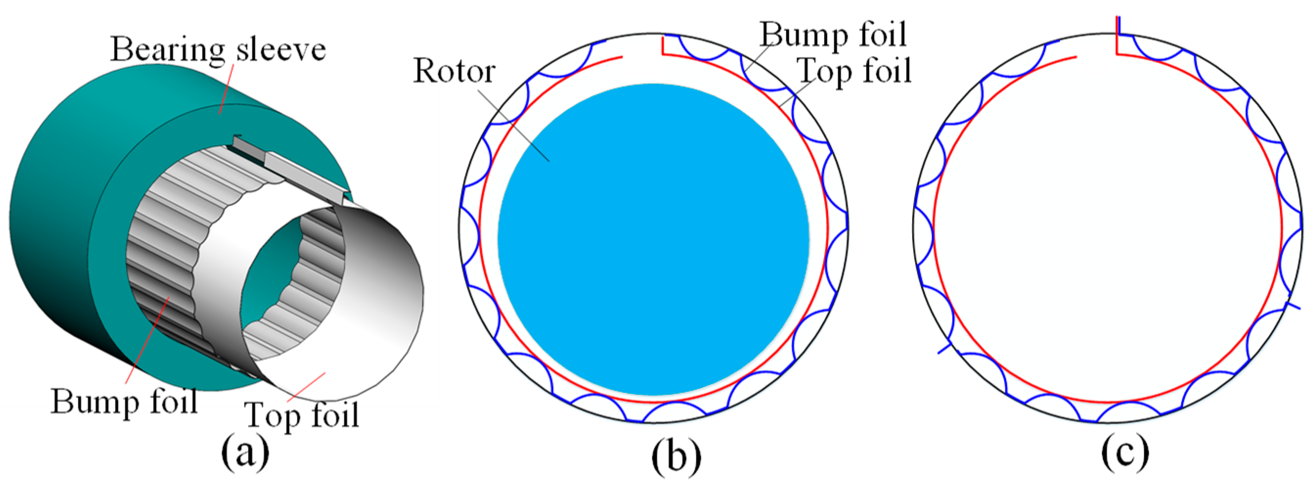
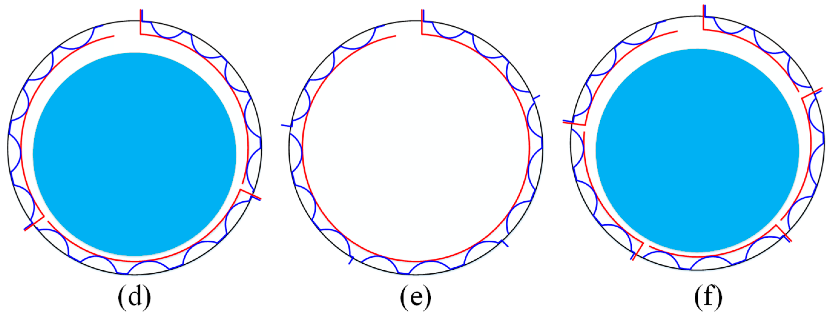
2.1. Foil Structures of Multi-Pad BFGB

The traditional BFGB has one top foil pad and one bump foil pad, as shown in Figure 1. In this paper, different types of BFGBs with multiple top and bump foil pads are also investigated. These are a BFGB with 1 top foil pad and 3 bump foil pads, a BFGB with 1 top foil pad and 5 bump foil pads, a BFGB with 3 top foil pads and 3 bump foil pads, and a BFGB with 5 top foil pads and 5 bump foil pads.

2.2. Finite Element Model

In the context of BFGBs, the top foil assumes a curved form as a result of cold rolling operation. Initially, the bump foil is fabricated into a flat configuration through the hydroforming technique. However, during the heat treatment phase, when it is wound around a circular rod, the bump foil also acquires a curved shape. Historically, most researchers have tended to model both the top and bump foils with planar structures in their studies. This traditional approach fails to account for the overall curvature characteristics of these foils, which may lead to inaccuracies in the analysis of their mechanical behaviors. In this research paper, we innovatively apply finite element methods to comprehensively analyze the structural deformations of the foils. To accurately capture the real behavior of the curved foils, we develop a novel stiffness model specifically tailored for the curved beam elements. This model enables us to more precisely simulate and understand the mechanical responses of the curved foils under various loading conditions, as graphically presented in Figure 2.
A typical curve beam element consists of two elemental nodes. Each of these nodes is associated with four degrees of freedom: the radial deflection w, the tangent displacement v, the rotating angle around the y direction θ y , and the tangent stretch strain S t . For the beam element, its key geometric features involve the curvature radius r, arc length l e s , beam width l e w , and beam thickness t.
The local coordinate system of the beam element is denoted as Osyz, with the origin positioned at the location of node 1. When it comes to any interpolating nodes within the curve beam element with radius r, the formulations for the radial deflection w and tangent deflection v are expressed as follows [28,35].
w   = D 1   +   D 2 s   +   D 3 s 2   +   D 4 s 3
v   = B 1   +   B 2 s   +   B 3 s 2   +   B 4 s 3
The rotating angle θ y is influenced by v and r and is formulated as θ y = w / s + v / r . The stretch strain considers the membrane strain and is formulated as S t =   v / s + w / r . The coefficients D 1 D 4 and B 1 B 4 in Equations (1) and (2) can be determined by the displacements of 2 elemental nodes, as shown in Equation (3).
q e = v 1 w 1 θ y 1 S t 1 w 2 v 2 θ y 2 S t 2 T
Based on the above definitions, the radial and tangential displacements of the interpolating node can be expressed as w = N w q e , v = N v q e , in which N w and N v are the interpolating functions of radial and tangent displacements, and the s is the variable.
The bending strain matrix B b s and the stretching strain matrix B m s are formulated as
B b s = z 2 N w s 2 N v r s B m s = N v s + N w r
The stiffness matrix of the curve beam element is derived as
K e = 0 l e s t 2 t 2 E B b s + B m s T B b s + B m s   d z d s
in which E is the elastic modulus of foil structure, and the foil thickness t is set as tp and tb for the top foil thickness and bump foil thickness, respectively. The structural parameters sb, hb, and lb in Figure 2 represent the bump pitch, bump height, and half bump wavelength, respectively. In fact, the value of Rb can be calculated using those of hb and lb based on the bump’s geometrical features. The arc length of the bump structure can also be obtained based on the above parameters. In addition, the arc length of the link structure between bumps can be calculated with the value of bump pitch sb.

2.3. The Internal Contact Constraints

The geometric features of the BFGBs give rise to intricate frictional contact constraints among adjacent bearing components. To begin with, the connection segments between individual bumps will come into contact with the bearing housing, which serves as the fixed base. As depicted in Figure 3, the peak nodes of each arc-shaped bump will make contact with the top foil in the circumferential directions. This may make it extremely challenging to create fully consistent finite element meshes for both the top and bump foils. To address this issue, instead of considering node-to-node contact, contact constraints between the bump peak nodes and the interpolating nodes within the curve beam elements of the top foil are proposed. These constraints are used to accurately describe the transfer of normal and frictional contact forces, enabling a more precise analysis of the mechanical behavior within the BFGB system.
The contact constraint between the top foil and bump foil is far more intricate than that between the bump foil and bearing sleeve. This complexity stems from the unique nature of the contact with the top foil. Here, the contact node is an interpolating node of a curve beam element.
The determination of a normal gap between specific contact nodes g n bt k is a function of two factors [36]. These are the radial displacements of the bump peak node w bt k and the interpolating node of the curve beam element on the top foil w t k . Mathematically, this relationship is precisely described by Equation (6):
g n bt k = w bt k w t k = w bt k N w q e k
where N w is the interpolating function of the curve beam element and q e k is the elemental displacement vector.
The tangent gap of this contact type g t bt k at the kth load step is constructed by the displacements of the contact node on bump peak v bt k of this load step and that of the last loading step. The expression of g t bt k is derived as
g t bt k = v bt k v bt k 1
Contact constraints are generated as a result of the contact gaps. When focusing on the contacts between the bump link sections and the bearing housing, the magnitude of the normal contact gap g n bh k is precisely the same as that of the nodal radial displacement. This relationship is clearly presented in Equation (8).
As for the tangent gap at the kth loading step g t bh k , its calculation is based on referencing the node position during the (k − 1)th loading step. This position, in turn, is determined by the tangent displacement of the contact node v bh k 1 .
g n bh k = w bh k g t bh k = v bh k v bh k 1
The contact energy of these two types of contact node pairs can be formulated as
c = λ n g n k + 1 η 2 ε t g t k 2 + η μ λ n g t k
In this context, λ n represents the Lagrange multiplier, which is used to denote the normal contact force. This multiplier plays a crucial role in contact mechanics calculations, as it helps to accurately account for the forces acting perpendicular to the contacting surfaces. ε t is the penalty factor, and it is associated with the tangent contact stiffness. The penalty factor is a key parameter in penalty-based contact methods. By adjusting the value of ε t , we can control how the system responds to the relative motion along the tangent direction of the contact interface. A higher value of ε t implies a stiffer response to tangential displacements. The η serves as a coefficient that indicates the sliding direction. When η = 0 , it means the contacting surfaces are in a sticking contact state, where there is no relative sliding between them. In contrast, when η = ± 1 , the surfaces are in a sliding contact state, and relative motion along the contact interface occurs. The μ stands for the friction coefficient, which quantifies the frictional interaction between the two contacting bodies. It is a dimensionless quantity that depends on the nature of the materials in contact and the surface conditions. A higher friction coefficient indicates a stronger resistance to relative motion between the surfaces.
The variation form of c bt is derived as
δ c = δ λ n g n k + λ n δ g n k + 1 η ε t g t k δ g t k + η μ λ n δ g t k = δ x k T G u
A further differential of δ c bt is formulated in matrix form:
Δ δ c   = δ x k T K u Δ x k
The generalized displacement vector of the contact node pair between the top foil and bump foil x bt k and the corresponding generalized contact force vector G u bt have the following formulations:
x bt k = v bt k w bt k q e k T λ n T G u bt = f bt t λ n λ n N w T g n bt k T
where f bt t = 1 η ε t g t bt k + η μ λ n .
The corresponding contact matrix K u bt in Equation (13) is derived as
  K u bt = 1 η ε t 0 0 η μ 0 0 0 1 0 0 0 N w T 0 1 N w 0
The displacement vector of the contact node pair between the bump foil and bearing sleeve x bh k and the contact force vector G u bh are formulated as
x bh k = v bh k w bh k λ n T G u bh = f bh t λ n g n bh k T
where f bh t = 1 η ε t g t bh k + η μ λ n .
The tangent contact matrix K u bh in Equation (15) has a size of 3 × 3 and is derived as
K u bh = 1 η ε t 0 η μ 0 0 1 0 1 0

2.4. Algorithm for Calculating Foil Deformation Considering Frictional Contacts

Section 2.2 established the finite element model of the curve beam element of the bump and top foil structures. Section 2.3 developed the model of contact constraints between the bump foil and top foil as well as between the bump foil and bearing sleeve. This section aims to develop an algorithm for calculating transient foil structural deformations in the time domain. Based on the Wilson-θ method, the acceleration of displacement vector of foil structures is expressed as [29]:
x ¨ G t + θ Δ t = 6 θ w 2 Δ t 2 x G t + θ Δ t x G t 6 θ w Δ t x ˙ G t 2 x ¨ G t
where θw is the iteration factor and is usually set as ≥1.4 to guarantee the convergence.
The variation form of the total potential energy δ   including the components that result from inertial force, foil structural deformation, contact constraints, and external force is as follows:
δ   = δ x G T M G 1 x G t + θ Δ t + δ x G T i = 1 N t K e t + j = 1 N b K e b x G + δ x G T i = 1 n c i G u bt + j = 1 n c j G u bh δ x G T F g + F M
where M G 1 = M G 6 θ w 2 Δ t 2 , M G is the mass matrix of the foil structure; F g is the aerodynamic force vector; F M = M G 2 x ¨ G t + 6 θ w Δ t x ˙ G t + 6 θ w 2 Δ t 2 x G t , Δ t is the time interval, and x ˙ G t is the velocity of the displacement vector of the foil structures.
The differential calculation of Equation (17) is derived as
Δ δ   = δ x G T M G 1 Δ x G t + θ Δ t + δ x G T i = 1 N t K e t + j = 1 N b K e b Δ x G + δ x G T i = 1 n c i K u bt + j = 1 n c j K u bh Δ x G
The final Newton–Raphson iteration formula can be obtained based on Equation (17) and Equation (18), and at each time step, the calculation algorithm for nonlinear foil deformation involves several steps:
(1)
Global stiffness matrix construction
The foil structure is discretized into curved beam elements through finite element modeling. Individual element stiffness matrices are systematically assembled to establish a comprehensive global stiffness matrix framework.
(2)
Contact constraint tangent matrix integration
The tangent stiffness matrix of contact constraints is coupled with the global stiffness matrix to formulate a Newton–Raphson iterative equation accounting for contact nonlinearity. This process employs the Lagrange multiplier method to enforce contact constraints, resulting in a mixed-stiffness system equation.
(3)
Intelligent contact state determination
A Coulomb friction-based sub-algorithm dynamically updates contact states through dual-criterion evaluation. One is the normal contact criterion: maintaining contact when λn < 0, and initiates separation when λn ≥ 0. The other is the tangential friction criterion: updating stick/slip states by comparing the tangential force magnitude ‖εt·gt‖ against the critical friction force μ·λn. A predictor–corrector strategy ensures rigorous enforcement of contact conditions during state transitions.
(4)
Convergence control
Convergence is achieved when both the displacement increment ‖Δu‖ < 1 × 10⁻⁸ and the residual force norms meet predefined thresholds. An adaptive load-step adjustment strategy optimizes computational efficiency while maintaining numerical stability.
This algorithm establishes a robust computational framework by synergistically coupling geometric, material, and contact nonlinearities. The automated contact state updating mechanism effectively addresses the path-dependent nature of frictional contact problems, providing a reliable solution for foil deformation analysis under complex operational conditions. The methodology demonstrates enhanced numerical robustness through its dual-convergence monitoring system and adaptive load-stepping protocol.

2.5. Gas Film Pressure Governing Equation

The transient gas film pressure distribution in the BFGBs can be obtained by numerically solving the quasi-static isothermal Reynolds equation in Equation (19). The finite difference method is applied to discretize and solve the Reynolds equation, and the detailed discretization processes can be found in the literature [36].
θ p ¯ h ¯ 3 p ¯ θ + D L 2 y ¯ p ¯ h ¯ 3 p ¯ y ¯ = Λ θ p ¯ h ¯ + 2 γ Λ t ¯ p ¯ h ¯
where p ¯ and h ¯ indicate normalized film pressure and thickness ( p ¯ = p / P a , h ¯ = h / C ini , where Pa is the ambient pressure and Cini is the initial radial bearing clearance); θ and y ¯ denote the circumferential and axial coordinates, respectively ( y ¯ = 2 y / L ); D and L denote the rotor diameter and bearing width; γ is the whirl frequency ratio ( γ = ω k / ω ); ω k and ω are the rotor whirl and rotating frequencies; and Λ is the bearing number ( Λ = 6 μ a ω / P a R / C ini 2 , where μ a is the gas viscosity and R is the rotor radius).
The updated gas film thickness h new is constructed by the initial gas film clearance C ini , the rotor eccentricity e and the rotor attitude angle ϕ, and the top foil deflection δ t . The expression of hnew is formulated as
h new = C ini + e cos θ ϕ + δ t
in which e and ϕ can also vary along the y direction if the rotor is not parallel with the bearing housing; δ t also has two dimensional distributions.

2.6. Multi-Field Coupled Model of Rotor–Bearing System

A schematic of the rotor-foil–bearing system in this paper is illustrated in Figure 4a. It is shown that two identical journal bearings are symmetrically distributed with respect to the rotor mid-plane supporting the rotor with a mass of 2 × Mr. In this condition, only cylindrical whirl motions exist, and the system can be simplified to that possessing one journal bearing and the rotor with a mass of Mr. Therefore, the rotor motions are governed by the dynamic equations in Equation (21), in which Mr is the rotor mass; x ¨ and y ¨ are the accelerations of the rotor in the x and y directions, respectively; Fx and Fy are the aerodynamic forces, which can be obtained by solving Equation (19); ub is the unbalance eccentricity; and g is the gravitational acceleration.
M r x ¨ = F x + M r u b ω 2 cos ω t M r y ¨ = F y + M r g + M r u b ω 2 sin ω t
When the rotor is floating on the gas foil bearing, owing to the aerodynamic force, the transverse displacements of the rotor will cause the distribution of gas film clearance and result in instantaneous variations in the aerodynamic force in turn. Besides the coupling effect between the rotor motions and aerodynamic field, the deformations of the foil structures are also forced to change due to the variations in aerodynamic forces, which in turn can change the gas film clearance distributions. Therefore, based on the above analyses, the rotor–BFGB system involves the coupling effects between multiple physical fields, and the internal relationships are depicted in Figure 4.

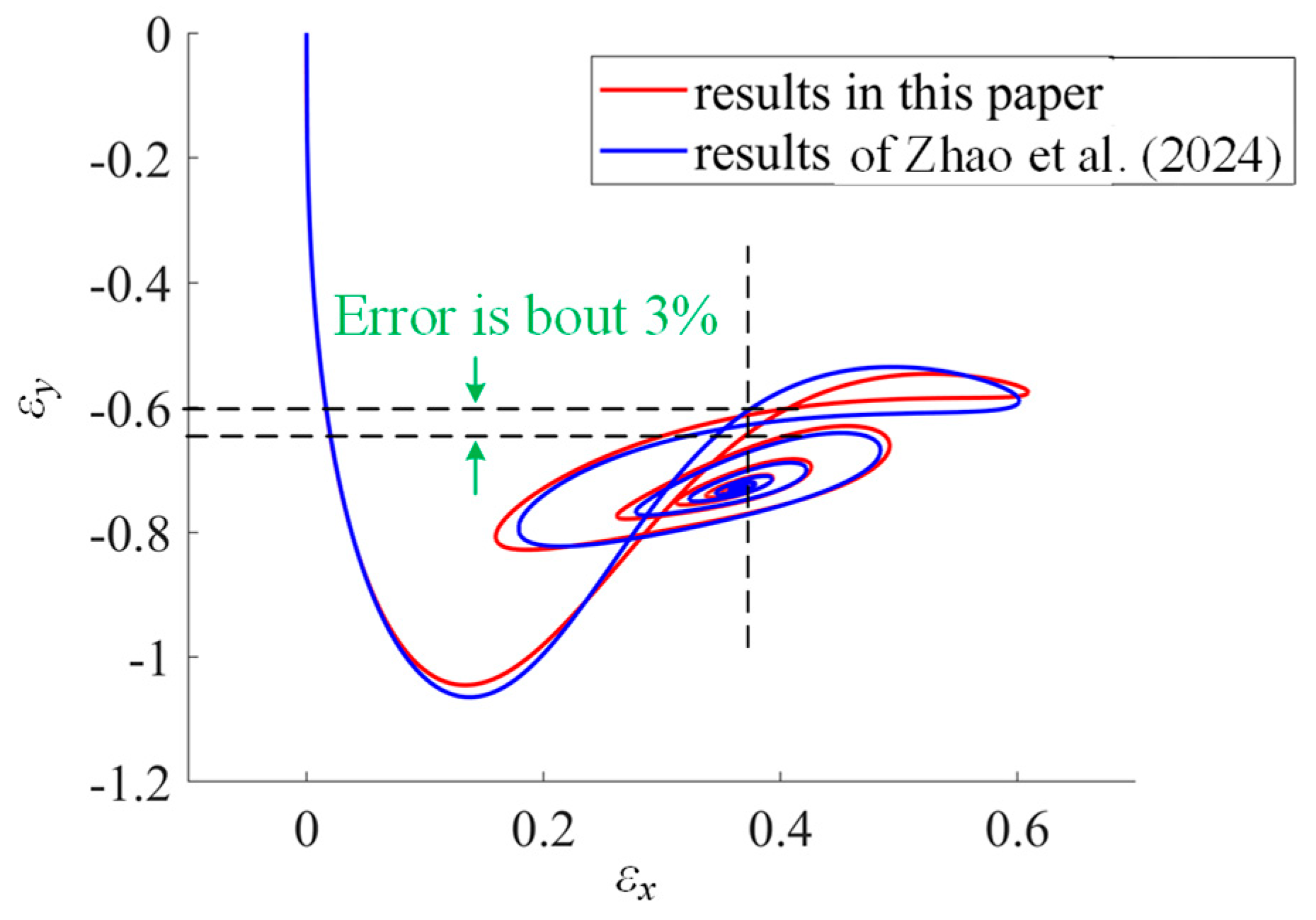
3. Model Validations

In order to validate the accuracy and reasonability of the dynamic model of the rotor–bearing system developed in Section 2, this section compares the simulation results of the rotor center trajectory based on the developed model in this paper with the results in the published literature [37]. The bearing parameter is as listed in Table 1, and the values in brackets are applied to conduct simulations of MP-BFGBs in Section 4. The rotor rotating speed for model validation is set as 12 krpm, and the rotor mass for one bearing is 3 kg.
The comparison between the calculated rotor trajectory this paper and those in Reference [37] is shown in Figure 5. Based on the coordinate system in Figure 4a, the horizontal and vertical axes εx and εy represent the rotor eccentricity ratios in the x and y directions, respectively. εx equals ex/Cini and εy equals ey/Cini, where ex and ey represent the rotor displacements or eccentricities in the x and y directions. It can be seen that the rotor center trajectories both start at the original point and gradually converge to the steady position. The rotor trajectory in this paper agrees very well with that in [37], and the final converged steady positions almost coincide. In addition, it is calculated that the maximum error of rotor eccentricity ratio in the y direction εx is about 3% under the same value of εx. The comprehensive comparisons demonstrate the accuracy and reasonability of the developed dynamic model of the rotor-foil–bearing system in this paper.

4. Results and Discussions

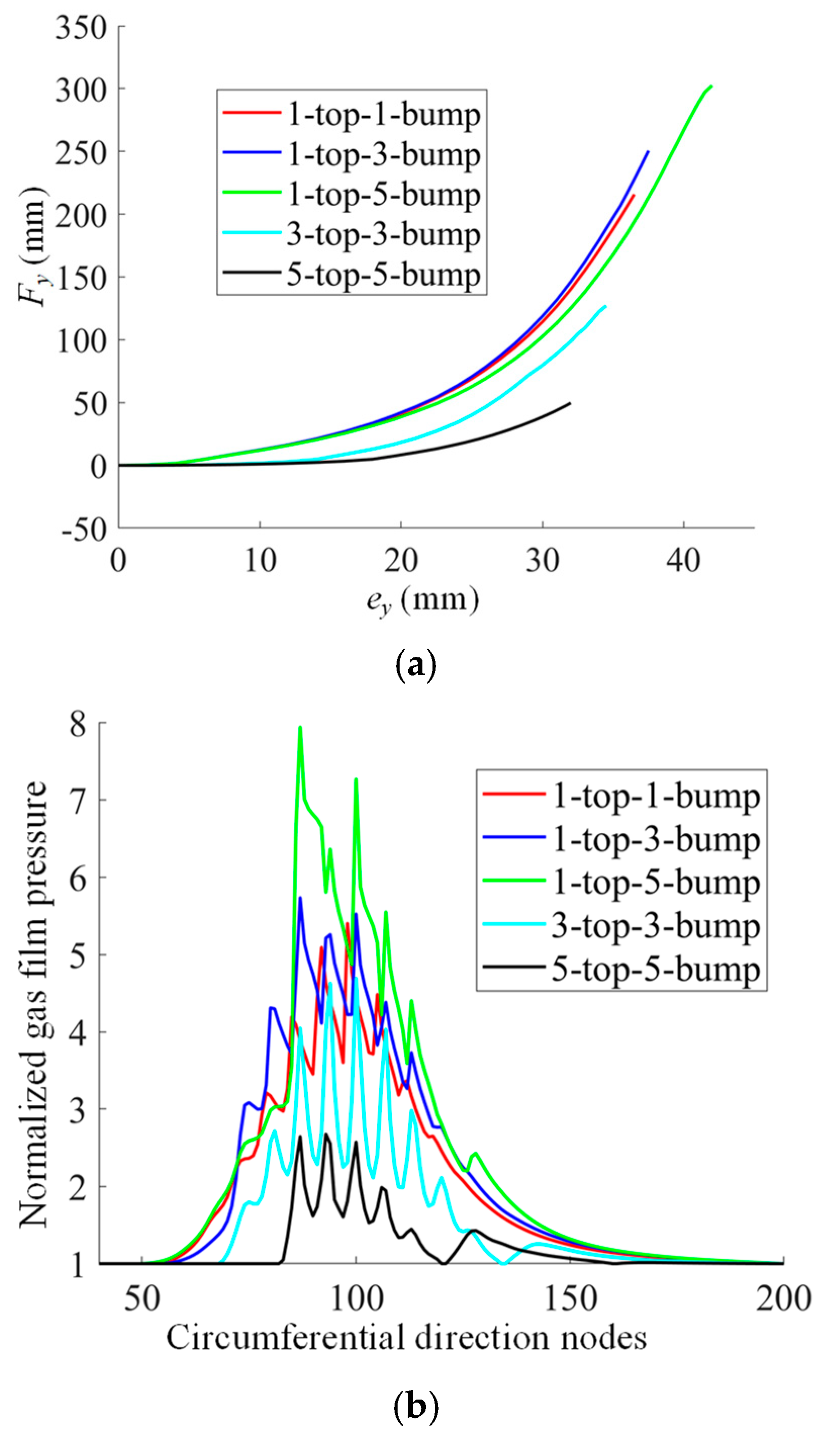
4.1. Static Performance Analysis of MP-BFGBs

Before investigating the dynamic performance of MP-BFGBs, its static characteristics, including the load capacities and distributions of gas film pressure, are calculated and discussed using a rotor speed of 30 krpm. Figure 6a illustrates the bearing load capacities versus the vertical rotor eccentricity of different bearing configurations. The different structures of MP-BFGBs involve bearings with one top foil and one bump foil, with one top foil and three bump foils, with one top foil and five bump foils, with three top foils and three bump foils, and with five top foils and five bump foils.
The loading curves all terminate when the minimum gas film thickness is reduced to 3 μm due to the increments in bearing load. The results show that the bearings with one top foil possess the evidently larger load capacities compared with the bearings with three and five top foils. The bearing with five top foils and five bump foils has the lowest load capacity, which results from the discontinuity of gas film pressure distribution. It can be inferred from the slopes of the loading curves in the initial loading stages with smaller rotor eccentricities that the bearings with one top foil possess almost the same stiffness values, which result from the gas film or represent the gas film stiffness. In addition, the gas film stiffness becomes lower when the top foil number decreases. The loading curves with one top foil and different bump foils show that the bearing stiffness is different at larger rotor eccentricities. This is due to the fact that the bearing stiffness is determined by the foil structure at larger load capacities or larger rotor eccentricity.
Figure 6b shows the gas film pressure distributions when the gas film thicknesses are 3 μm for these different bearing configurations. It is obvious that the peak gas film pressure is the highest for the bearing with one top foil and five bump foils. And only two gas film lubrication fields provide the aerodynamic forces for the bearings with three and five top foils.
The reason for the influence of the number of top foils on the bearing static performance can be explained as follows. Increasing the number of top foil pads will divide the circular gas film clearance into several parts. Each part of gas film clearance has two ambient boundaries in the circumferential direction, and this discontinuity in gas film clearance will hinder the continual elevation in gas film pressure when the gas is brought along the clearance converging direction. Therefore, the maximum gas film pressure is lower for a larger number of top foil pads, and the load capacity and gas film stiffness are also lower.

4.2. Dynamic Performance Analysis of MP-BFGBs

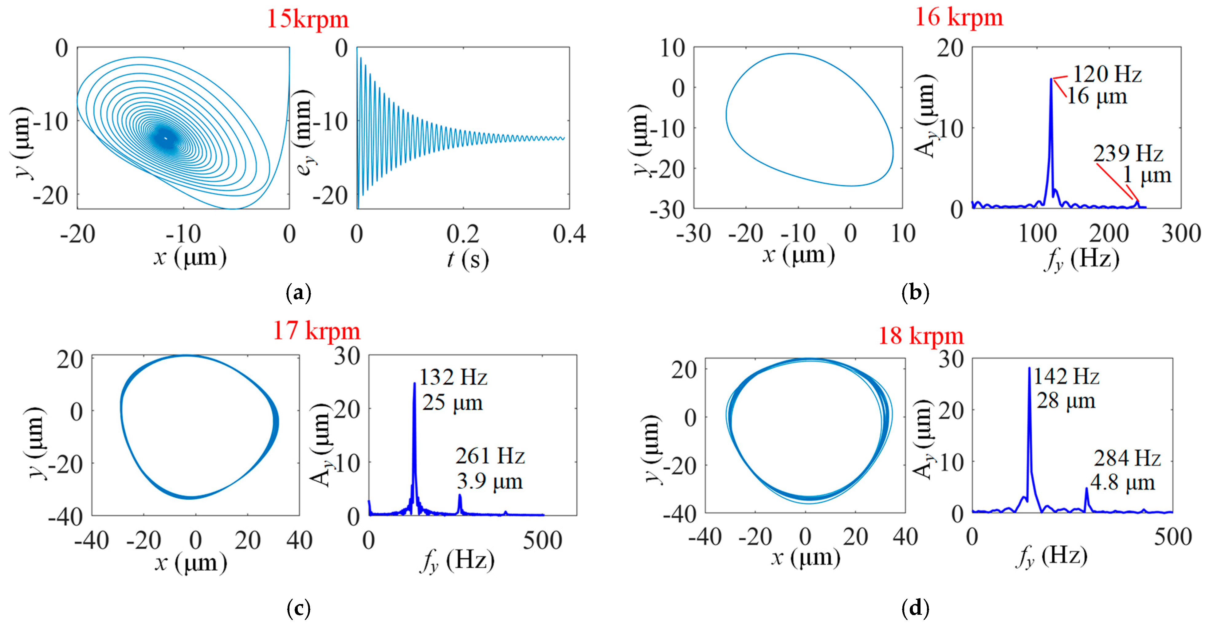
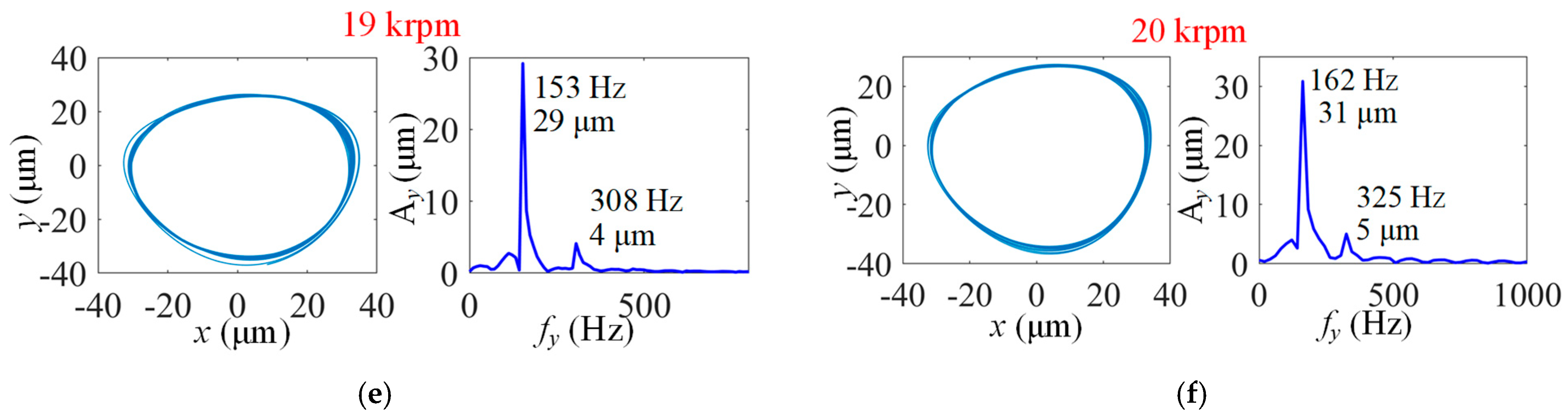
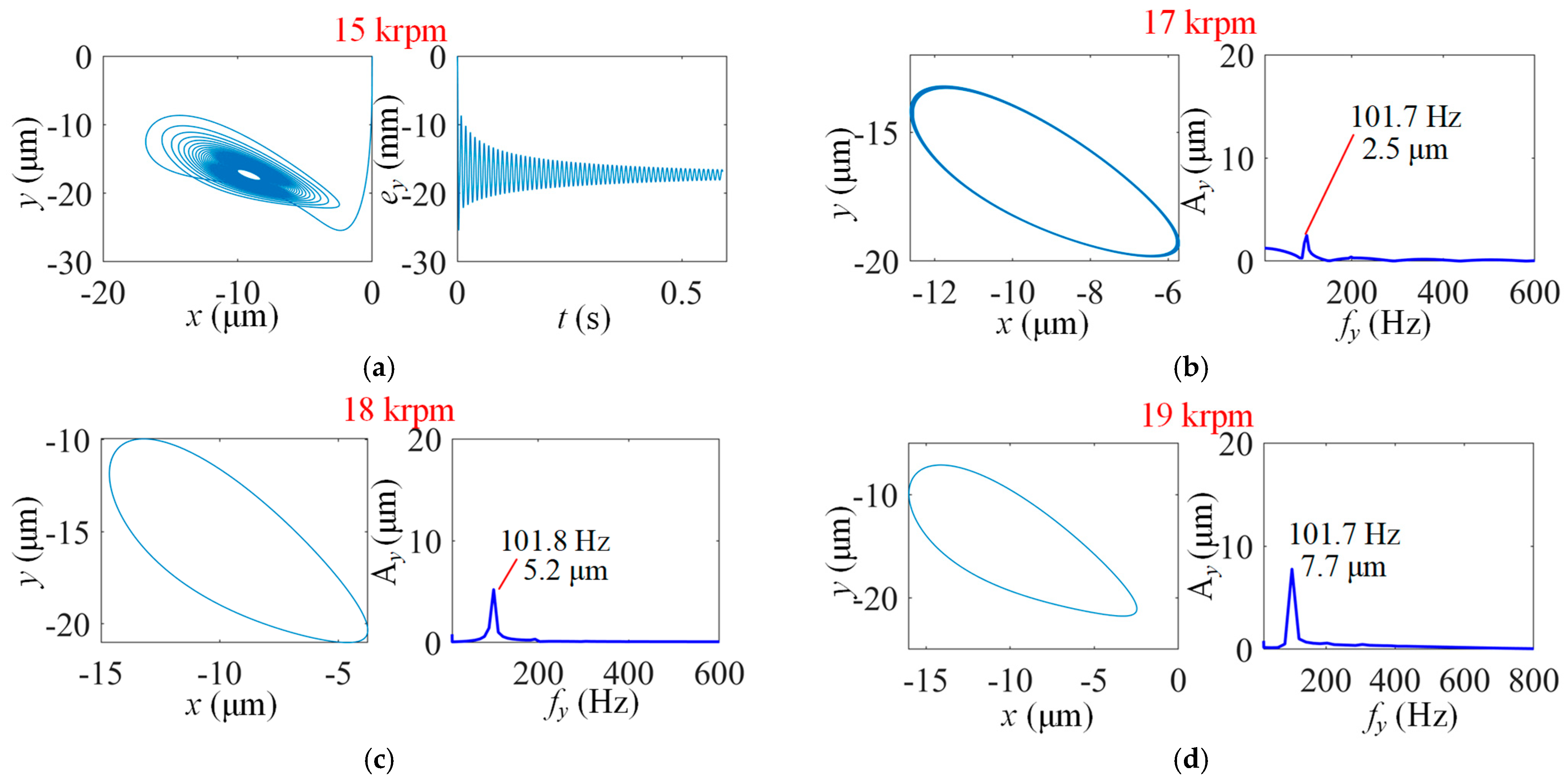
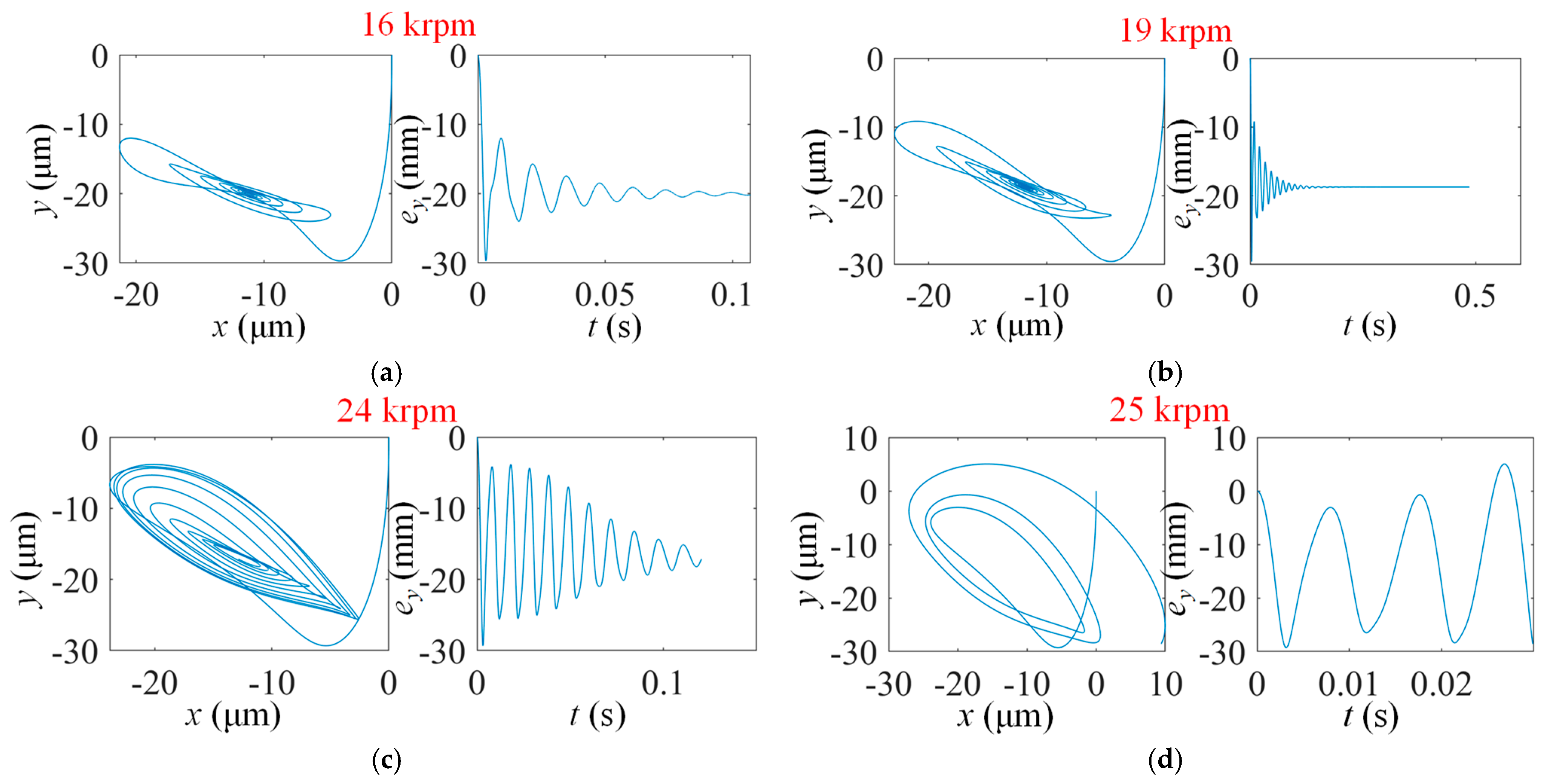
4.2.1. Self-Excitation Analysis of Rotor–Bearing System

Firstly, the rotor dynamic responses caused by system self-excitations are presented, which omit the forced excitations caused by rotor-unbalanced mass. The simulation results for different the configurations of MP-BFGBs are discussed as follows.
(1)
Results for MP-BFGB with one top foil pad and one bump foil pad
Figure 7 illustrates the results for the bearing with one top foil and one bump foil. At a rotor speed of 15 krpm, the trajectory of the rotor center starts from the original point and gradually converges to a stable point after cycles of vibrations and so does the vertical displacement ey. The x and y in in Figure 7 represent the positions or displacements of the rotor center in Cartesian coordinates as shown in Figure 4a. When the rotor speed increases to 16 krpm, the trajectory of the rotor center cannot converge to a fixed node but on a circle-shaped trace. After the FFT transformation, the obtained spectrum diagram shows that there are two vibration components corresponding to two different frequencies. The vibration component of lower frequency has a larger amplitude value, which is about 16 μm, and the vibration amplitude of the higher-frequency component is only about 1 μm. It is worth noting that the higher frequency (239 Hz) is about twice the value of lower frequency, which is actually lower than the synchronous frequency (266.7 Hz). When the rotor speed is further increased to 17 krpm, the trajectory of the rotor center still cannot converge to a fixed point, and the vibration amplitudes and frequencies both increase for the different components. In detail, the lower frequency value increases from 120 Hz to 132 Hz, which is still the half of the higher frequency value, and the amplitude increases from 16 to 25 μm for the lower-frequency vibration.
Similarly, the vibration amplitudes and frequencies gradually increase when the rotor speed further increases from 18 to 20 krpm. If the rotor speed increases to 21 krpm, the minimum gas film thickness will reach a small value that is less than 1 μm, and the rotor is deemed to hit the top foil, and the simulation process is terminated under this condition.
(2)
Results for MP-BFGB with one top foil pad and three bump foil pads
Figure 8 illustrates the rotor dynamic responses caused by the system self-excitation for the bearing with one top foil and three bump foils. Similar to the results in Figure 7, when the rotating speed is 15 krpm, the rotor is able to stabilize on a point. However, if the rotor speed is increased to 16 krpm, the trajectory of the rotor center is on a limit circle, indicating the arising of sub-synchronous vibrations. The frequency of the sub-synchronous vibrations is about 122 Hz, which is close to the result in Figure 7b, and the vibration amplitude is 19.6 μm, which is larger than the result in Figure 7b. If the rotor speed is further increased, the sub-synchronous vibrations still exist, and their frequencies increase.
Different from the results in Figure 7, the rotor vibration amplitudes supported by the bearing with one top foil and three bump foils are obviously smaller when the rotor speed is above 19 krpm. This means that the limit rotor speed is as high as 22 krpm, over which the minimum gas film thickness is less than 1 μm.
(3)
Results for MP-BFGB with one top foil pad and five bump foil pads
Figure 9 illustrates the rotor dynamic responses caused by the system self-excitation for the bearing with one top foil and five bump foils. Similar to the results in Figure 7 and Figure 8, the rotor is able to converge to a point when the rotating speed is 15 krpm. However, the trajectory of the rotor center cannot be stabilized on a point but on a limit circle if the rotor speed is further increased. The vibration frequencies of the sub-synchronous components are almost the same as the results in Figure 7 and Figure 8 at each rotor speed, but there exists a certain difference in the vibration amplitudes for different bearing structures. When compared with the bearing with one top foil and three bump foils, the vibration amplitude is lower at rotor speeds of 16 krpm, 17 krpm, and 18 krpm and is larger at the higher rotor speeds for the bearing with one top foil and five bump foils. And the limit rotor speed is thus lower.
(4)
Results for MP-BFGB with three top foil pads and three bump foil pads
From the above results and analyses, it can be seen that the trajectory of the rotor center can converge to a fixed point at a rotor speed of 15 krpm and has sub-synchronous vibrations above speeds of 16 krpm when supported by bearings with one top foil and different bump foils. However, when the number of top foils is increased to three, the dynamic performance of the bearing seems to be much different. As shown in Figure 10, the rotor can stabilize on a point at speeds of 15 krpm and 16 krpm and tends to have sub-synchronous vibrations at a speed of 17 krpm, which is higher than the conditions of one top foil. Mostly, the vibration amplitudes are much smaller than the results in Figure 7, Figure 8 and Figure 9 at different rotor speeds, and the vibration frequencies are lower, which almost do not change with the rotor speed (about 101 Hz).
The sub-synchronous vibration amplitudes gradually increase from about 2.5 μm to 9.2 μm when the rotor speed increases from 17 krpm to 21 krpm. At 22 krpm, the rotor center even cannot converge on the limit circle, manifesting an evident diverging trend. This instability phenomenon is different from the conditions for bearings with one top foil, in which the simulations are terminated by very small gas film thickness rather than the evidently diverging trajectory of the rotor center. The reason for the above comparison results is probably the stiffness difference in aerodynamic gas films.
(5)
Results for MP-BFGB with five top foil pads and five bump foil pads
Figure 11 shows the rotor dynamic responses supported by the bearing with five top foils and five bump foils. The number of lubrication fields is increased to five considering the ambient boundary conditions. The results indicate that the rotor center is able to stabilize on a point over a large range of rotor speeds from 15 to 24 krpm, and some simulation results such as 15 and 17 krpm have been omitted to minimize the length of this article. The rotor becomes unstable at a rotor speed of 25 krpm, manifesting the abrupt divergence of rotor trajectory without experiencing the period of critical stability or period of limit circle. This is different from the cases of the MP-BFGB with one top foil and three top foils.
(6)
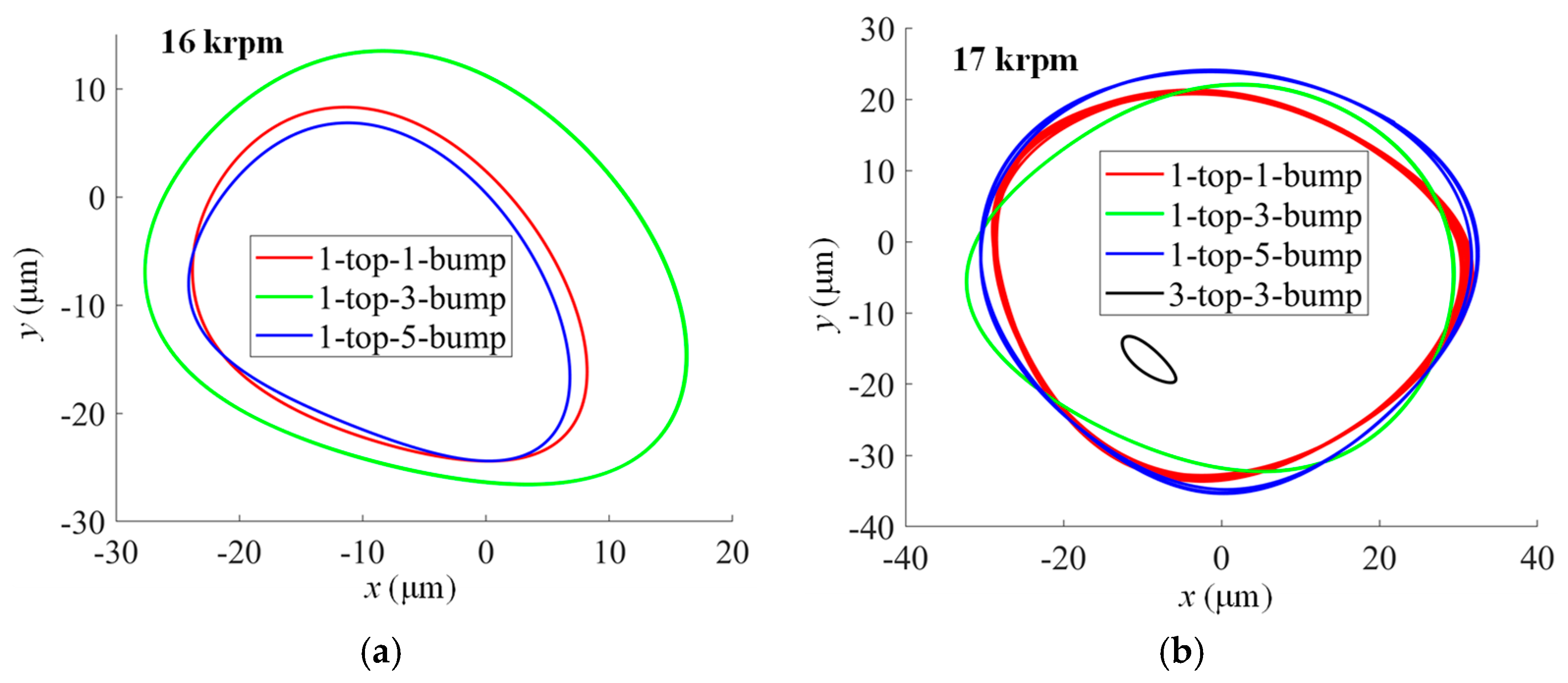
Analyses and discussions
As shown in Figure 12, in order to compare the rotor sub-synchronous vibration amplitudes supported by different types of MP-BFGBs in a more appropriate way, the rotor center trajectories of different conditions are presented in the same subfigures. When the rotor speed is 16 krpm, the size of the rotor center trajectory supported by the bearing with one top foil and three bump foils is the largest. At this rotor speed, for the conditions of three and five top foils, the rotor converges to a fixed point. As the rotor speed is increased to 17 krpm, the size of the rotor center trajectory for the condition with one top foil and five bump foils becomes the largest, and that with three top foils and three bump foils is apparently the smallest. From 18 krpm to 20 krpm, the size of the rotor center trajectories for the condition with one top foil and three bump foils is the smallest among the cases with one top foil. Therefore, the simulations can be carried out up to 22 krpm in this condition considering the limit of minimum gas film thickness, as discussed based on the results in Figure 8.

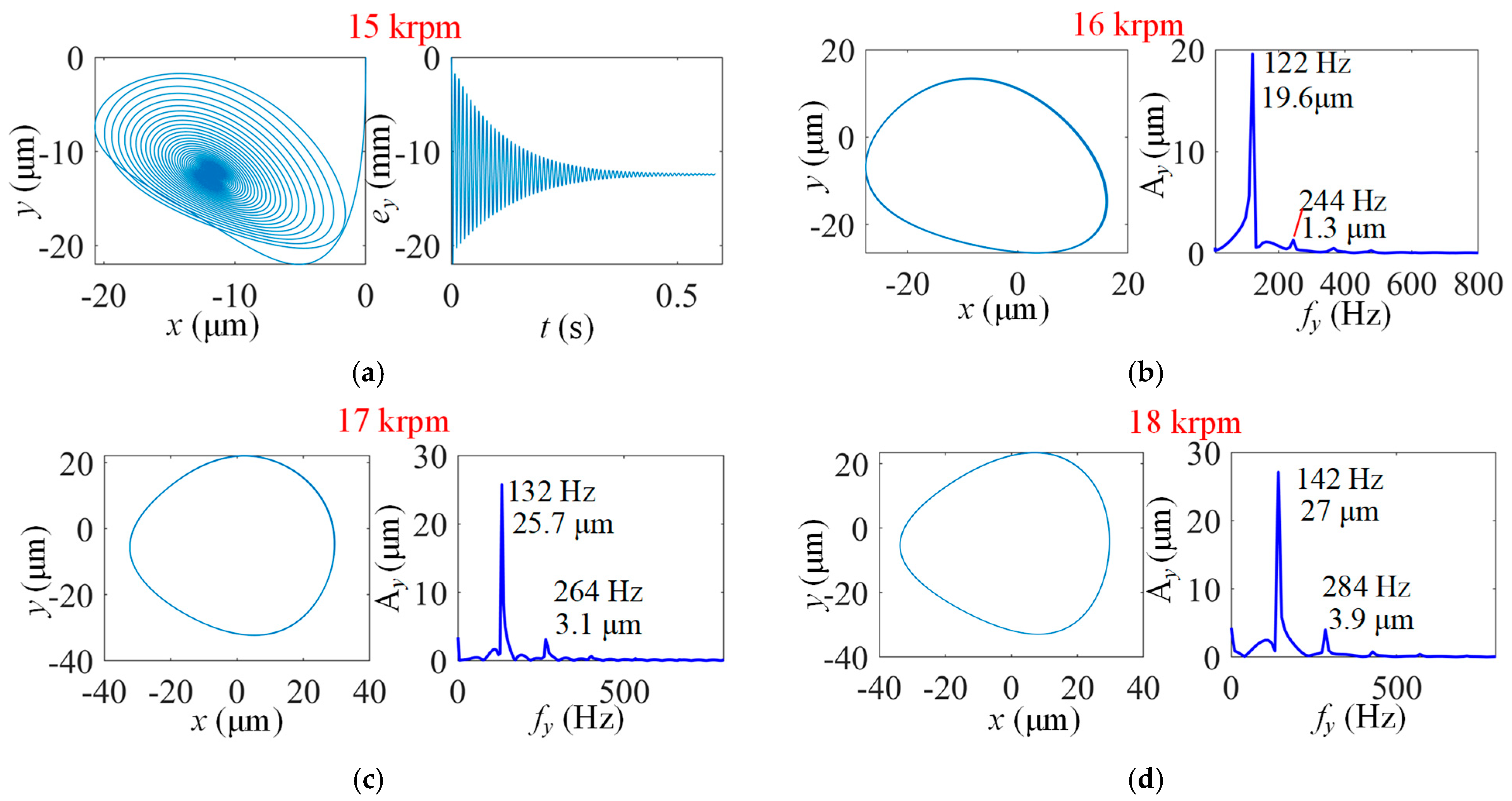
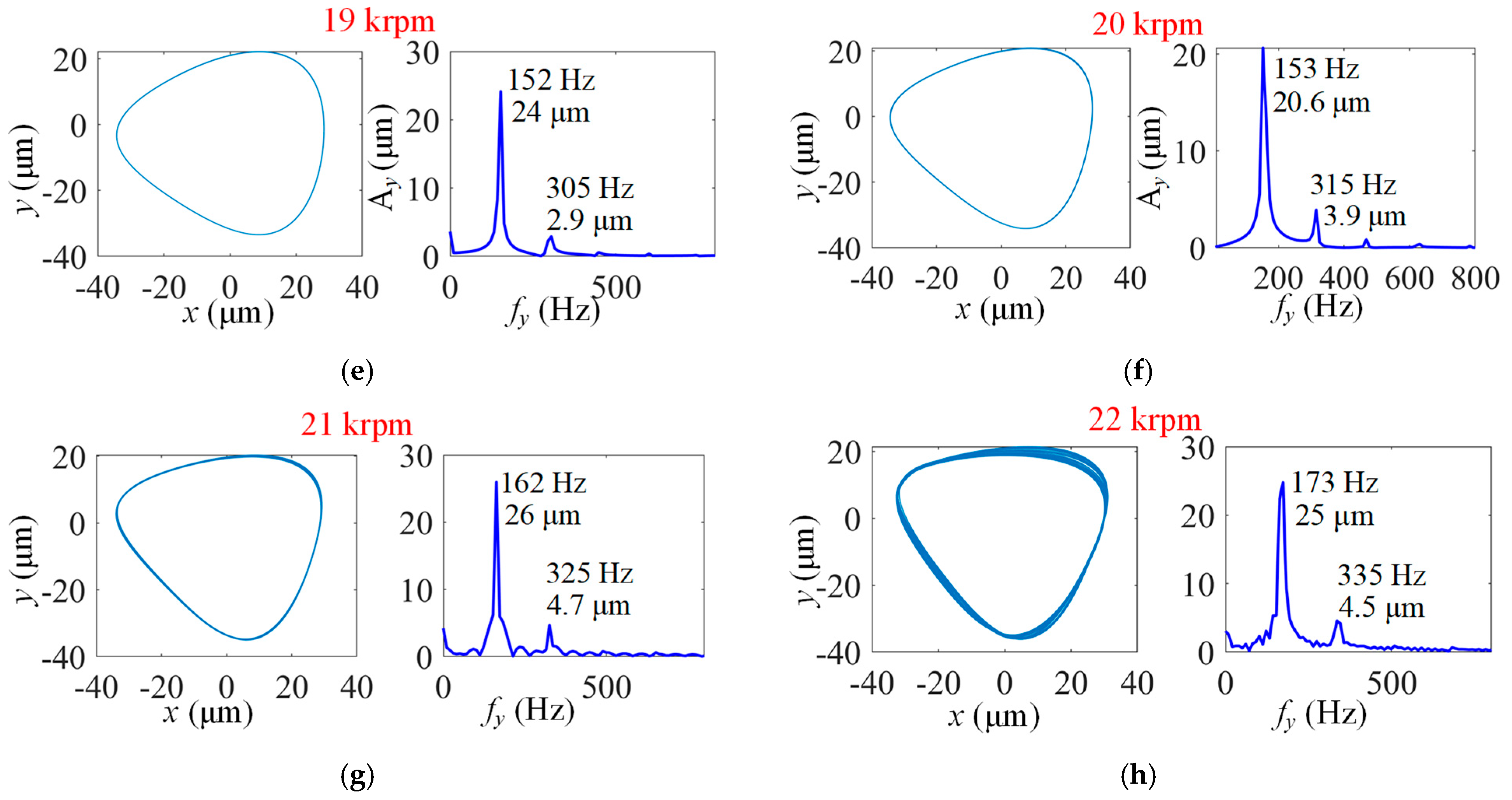
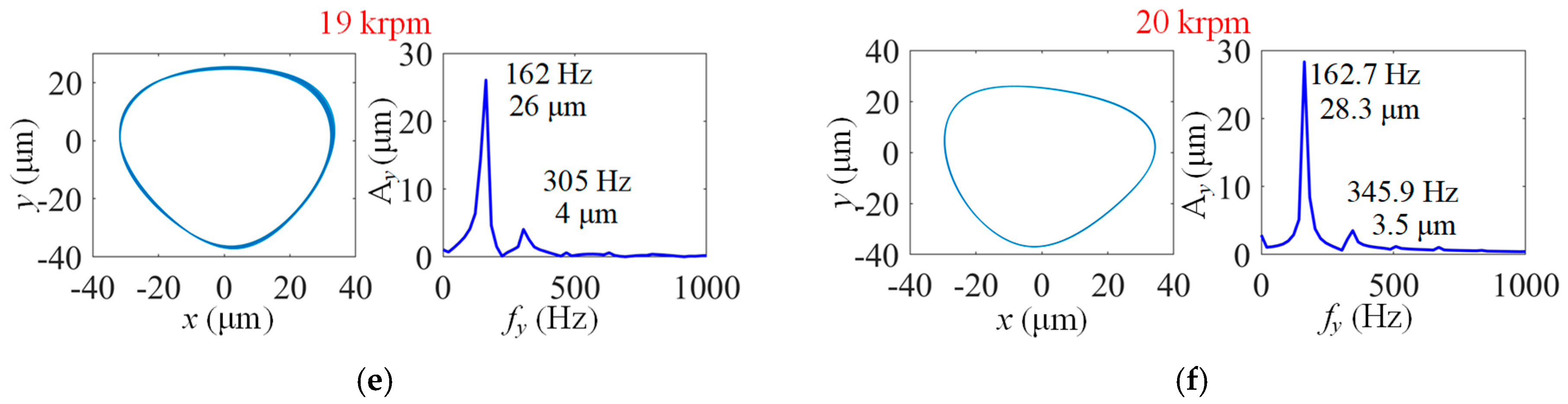
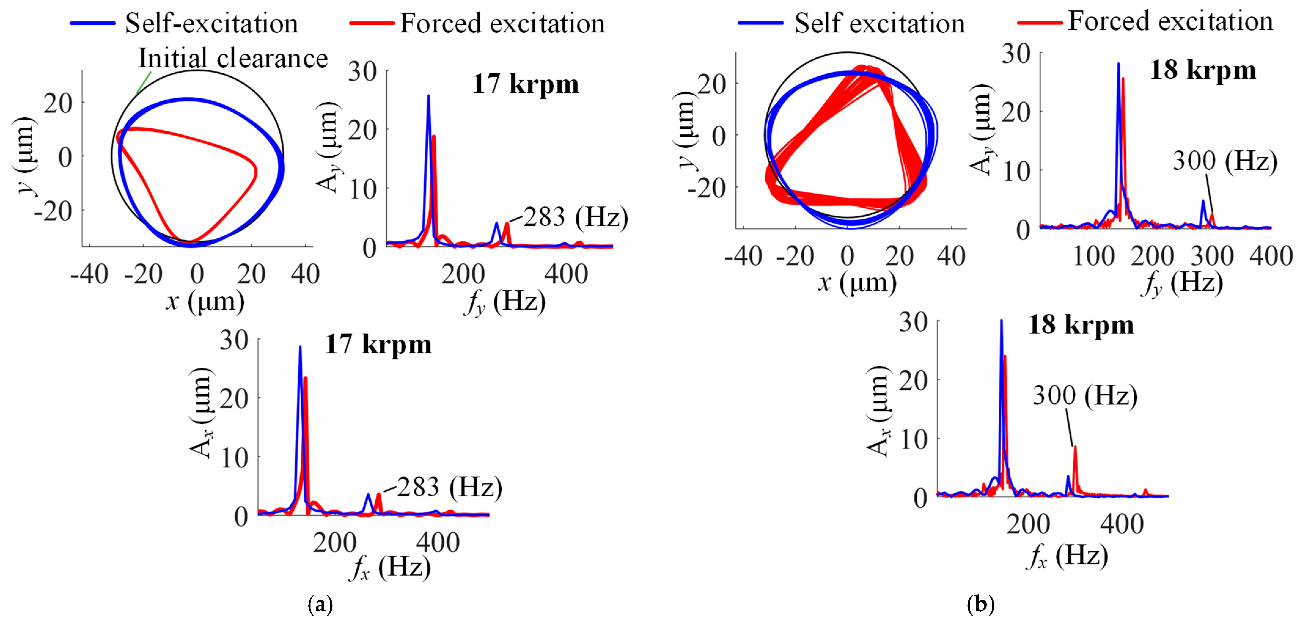
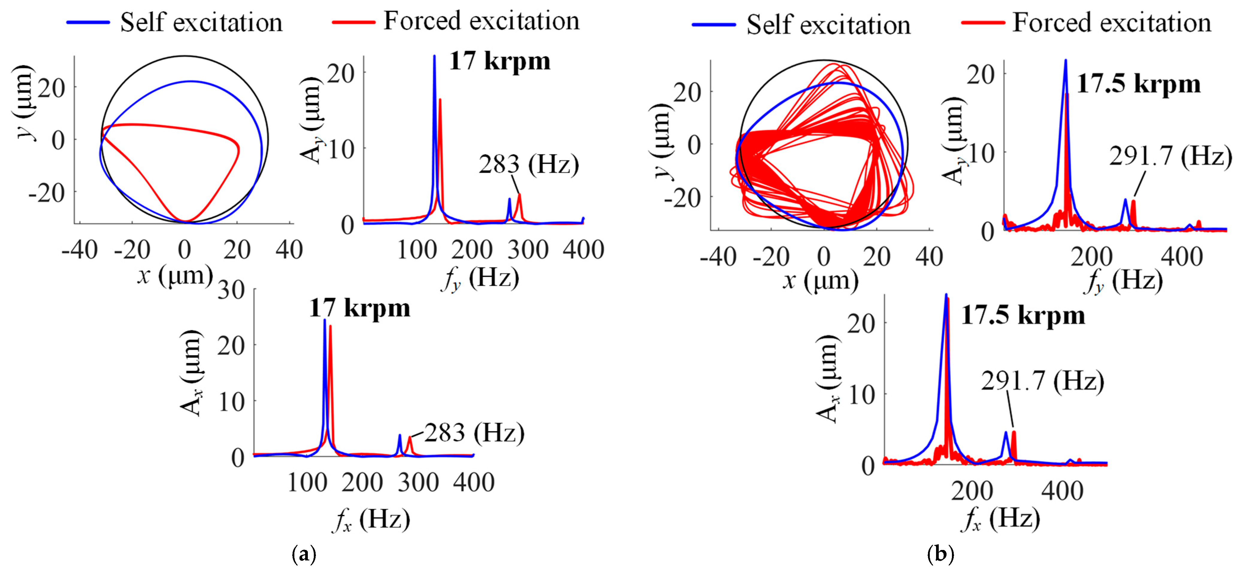
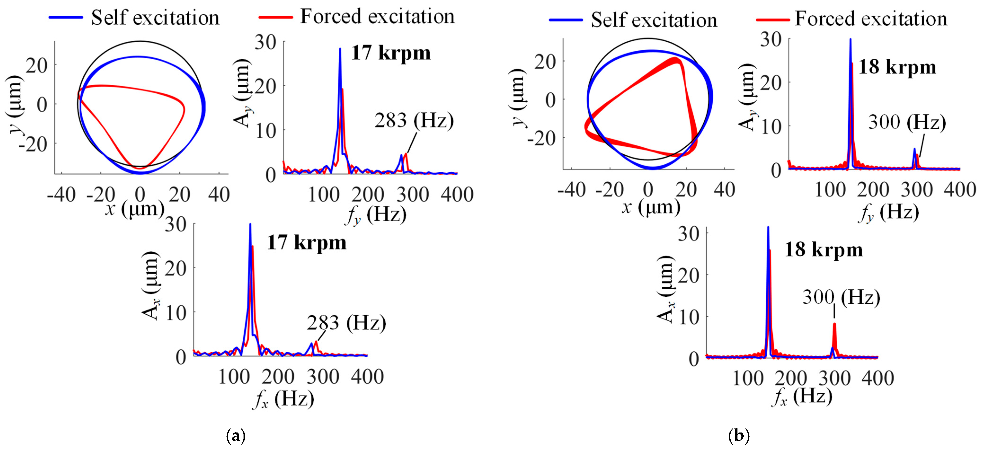
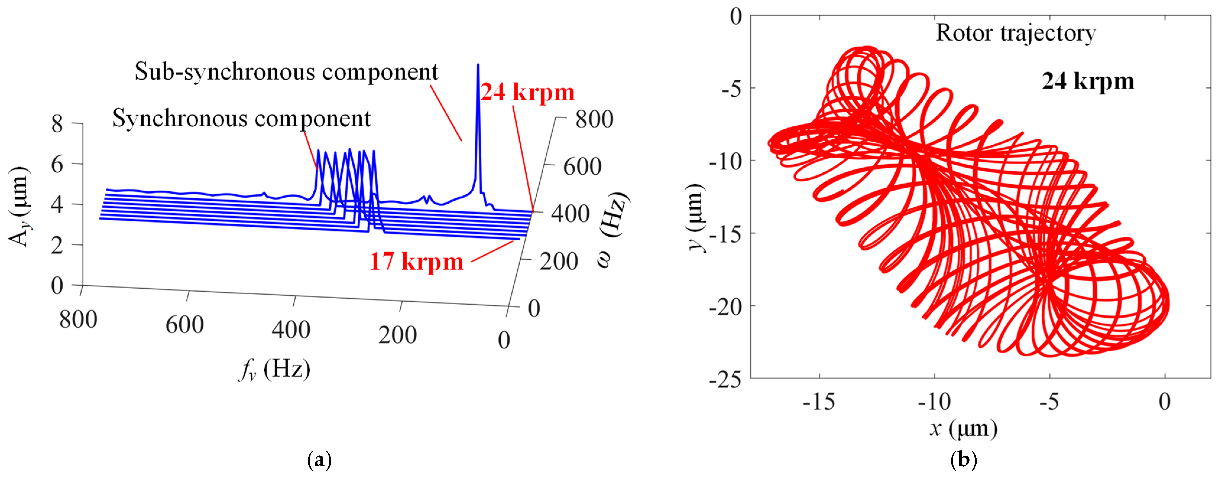
4.2.2. Rotor Forced Excitation Responses

Section 4.2.1 investigates the rotor dynamic responses caused by the system self-excitation vibrations, in which the external excitation forces are not considered. In this section, the rotor dynamic responses, also considering the forced excitations caused by rotor unbalance mass, are studied.
(1)
Results for MP-BFGB with one top foil pad and one bump foil pad
For the bearing with one top foil and one bump foil, Figure 13 compares the rotor dynamic responses caused by the system self-excitation and by the forced excitation of unbalance mass. Firstly, it can be seen that the size of the rotor center trajectory is apparently smaller when considering the forced excitation at a rotor speed of 17 krpm. The shape of the rotor center trajectory resembles a triangle under the forced excitation condition while it resembles a circle under the self-excitation condition. From the spectrum diagrams of rotor displacements in the x and y directions, it is clear that the synchronous vibration component (283 Hz) appears when the rotor unbalance mass is considered and the frequency of sub-synchronous vibration component is almost half of the synchronous component. This is the so-called half-speed whirl motion. However, it shows that the frequency of sub-synchronous vibration (less than 200 Hz) is lower under the condition of self-excitation than the result under the forced excitation condition.
When the rotor speed increases to 18 krpm, the size of the rotor center trajectory experiences an evident increment under the forced excitation. This enlargement is mainly due to the increments in sub-synchronous vibration amplitude in the y direction and synchronous vibration amplitude in the x direction. The drastic increments in vibration amplitudes with the rotor speed lead to a fast reduction in the gas film thickness. Under the forced excitation, the simulation is terminated due to the limitation of the minimum gas film thickness at a rotor speed of 19 krpm, which is lower than the critical speed for the self-excitation condition (21 krpm).
(2)
Results for MP-BFGB with one top foil pad and three bump foil pads
As discussed in Section 4.2.1, when the bearing is equipped with one top foil and three bump foils, the limit rotor speed is the highest among the bearing structures with one top foil under the self-excitation condition. However, for this bearing configuration, the gas film thickness first reaches the minimum threshold (1 μm) when the rotor speed just increases to 18 krpm under the forced excitation. As shown in Figure 14, the sub-synchronous vibration amplitude in the x direction under forced excitation is close to the result under self-excitation from 17 krpm, and the amplitude grows rapidly with the rotor speed manifesting the same value as that under self-excitation under a rotor speed of 17.5 rpm. The size of the rotor center trajectory also grows rapidly, exceeding the initial bearing clearance in many regions along the circumferential direction.
(3)
Results for MP-BFGB with one top foil pad and five bump foil pads
Under the self-excitation without rotor unbalance mass, the rotor supported by the bearing with one top foil and five bump foils can be increased to 20 krpm before the minimum gas film thickness reaches the threshold. However, when the rotor unbalance mass is considered or under the forced excitation, the minimum gas film thickness will be less than 1 μm if the rotor speed reaches 19 krpm. This indicates that the forced excitation tends to restrict the rotor from operating at higher speeds. From the comparisons of vibration amplitudes between self-excitation and forced excitation conditions in Figure 15, it is found that the increments in sub-synchronous vibration amplitude in the y direction and the synchronous vibration amplitude in the x direction are responsible for the size enlargement of the rotor center trajectory. This is similar to the comparison results with the one top foil and one bump foil condition in Figure 13.
(4)
Results for MP-BFGB with three top foil pads and three bump foil pads
Figure 10 shows that the sub-synchronous vibrations are obtained from 17 krpm to 21 krpm for the MP-BFGB with three top foils and three bump foils, and the vibration amplitude gradually increases until the divergence of the rotor center trajectory at 22 krpm. However, when the rotor unbalance mass is considered, the synchronous vibration component exists only from 17 krpm to 23 krpm and the sub-synchronous component appears only at 24 krpm, as shown in Figure 16. The rotor trajectory diverges at 25 krpm, which is higher than the self-excitation condition. The influence of forced excitation on the rotor dynamic responses for the bearing structure with multiple top foils is different from the results of bearings with one top foil. In detail, the forced excitation increases the limit rotor speed.
(5)
Results for MP-BFGB with five top foil pads and five bump foil pads
In Figure 11, for the MP-BFGB with five top foils and five bump foils, it shows that the rotor center trajectory continuously converges to a point without the existence of sub-synchronous components until it diverges at 25 krpm under the self-excitation condition. When the rotor unbalance mass is considered, the synchronous vibration component is obtained, and the amplitude shows a decreasing trend with an increase in the rotor speed, as shown in Figure 17. The sub-synchronous vibration is also not observed over a large range of rotor speeds until the divergence of the rotor center trajectory at 29 krpm, which is much higher than the critical speed for stability under the self-excitation condition.

5. Conclusions

This paper mainly conducts investigations on the rotor dynamic responses supported by different types of multi-pad bump foil gas bearings (MP-BFGBs). A finite element model of the foil structures is developed based on the curve beam element, and internal contact constraints are introduced based on contact mechanics. The multi-field coupled model is also established considering the interaction between foil structures, aerodynamic gas films, and rotor dynamics. The load capacity of MP-BFGBs and rotor dynamic responses supported by MP-BFGBs under system self-excitation and forced excitation are calculated and discussed. The main conclusions of this paper are as follows:
(1)
Bearings with one top foil have significantly higher load capacities than those with three or five top foil pads. The load capacity of the MP-BFGBs and the gas film stiffness both decrease as the number of top foil pads increases.
(2)
Rotors are more likely to experience sub-synchronous vibrations when supported by a bearing with one top foil. That is, higher gas film stiffness more easily causes sub-synchronous vibration.
(3)
Among bearings with one top foil pad, structures with three bump foils result in lower sub-synchronous amplitudes at higher rotor speeds.
(4)
The bearing with five top foils and five bump foils allows the rotor to reach the highest critical stability speed under both self-excitation and forced excitation conditions.
(5)
Considering the forced excitation lowers the maximum rotor speed for the one top foil bearing but raises the critical speed for stability for bearings with three and five top foils.

Author Contributions

Conceptualization, J.Z.; Methodology, L.Z., H.H. and C.L.; Software, L.Z. and C.L.; Validation, L.Z., H.H. and C.L.; Formal analysis, C.L.; Investigation, L.Z. and H.H.; Writing—original draft, L.Z.; Writing—review & editing, C.L. and J.Z.; Supervision, J.Z.; Project administration, J.Z.; Funding acquisition, J.Z. All authors have read and agreed to the published version of the manuscript.

Funding

This research received no external particular funding.

Data Availability Statement

Data is contained within the article.

Conflicts of Interest

Authors Lei Zhao and Hongyang Hu were employed by the company AVIC Xinxiang Aviation Industry (Group) Co., Ltd. The remaining authors declare that the research was conducted in the absence of any commercial or financial relationships that could be construed as a potential conflict of interest.

Nomenclature

Bbs, BmsBending and stretching strain matrices of the curve beam element
CiniBearing radial clearance (m)
DRotor diameter (m)
eRotor eccentricity (m)
εtPenalty factor in the tangent direction
EElastic modulus of the foil material (N/m2)
Fx, FyBearing reaction forces in the x and y directions (N)
FgAerodynamic force vector
g n bt k , g t bt k Normal and tangent contact gaps between the bump foil and top foil at the kth load step (m)
g n bh k , g t bh k Normal and tangent contact gaps between the bump foil and bearing sleeve at the kth load step (m)
G u bt , G u bh General contact force vectors of the different types of contact constraints
K u bt , K u bh Tangent contact matrices of the different types of contact constraints
K e t , K e b Stiffness matrices of the curve beam element of the top foil and bump foil, respectively
L Bearing width (m)
M G Global mass matrix of the foil structures
les, lewArc length and axial width of the curve beam element (m)
N w , N v Interpolating functions of the radial and tangent displacements of the curve beam element
η Factor indicating the sliding direction of the contact node pair
q e Displacement vector of the curve beam element
rCurvature radius of the curve beam element (m)
Rtop, Rb, RlinkCurvature radius of the top foil, bump foil, and link structure between adjacent bumps (m)
RRotor radius (m)
sCircumferential coordinates of the curve beam element
tThickness of the curve beam element (m)
ΔtTime interval for calculating transient rotor responses (s)
w, vRadial and tangential displacements of the curve beam element (m)
ωRotor rotating speed (rad·s−1)
x G Global displacement vector of the foil structures
μFriction coefficient between foil leaves
μaGas viscosity (Pa·s)
θ w Iteration factor of the Wilson-θ method
θ y Nodal rotational angle of the curve beam element (rad)
λ n Lagrange multiplier or contact force in the normal direction
δ t Foil deformation distribution
ϕRotor attitude angle (rad)
Λ Bearing number
c Contact energy per contact node pair
Total potential energy stemming from both elastic strain and contact constraints

References

  1. DellaCorte, C.; Valco, M.J. Load Capacity Estimation of Foil Air Journal Bearings for Oil-Free Turbomachinery Applications. Tribol. Trans. 2000, 43, 795–801. [Google Scholar] [CrossRef]
  2. Agrawal, G.L. Foil Air/Gas Bearing Technology—An Overview. In Proceedings of the ASME International Gas Turbine & Aeroengine Congress & Exhibition, Orlando, FL, USA, 2–5 June 1997; American Society of Mechanical Engineers: New York, NY, USA, 1997. [Google Scholar]
  3. Heshmat, H. Advancements in the Performance of Aerodynamic Foil Journal Bearings: High Speed and Load Capability. J. Tribol. 1994, 116, 287–294. [Google Scholar] [CrossRef]
  4. DellaCorte, C.; Lukaszewicz, V.; Valco, M.J.; Radil, K.C.; Heshmat, H. Performance and Durability of High Temperature Foil Air Bearings for Oil-Free Turbomachinery. Tribol. Trans. 2000, 51, 665–671. [Google Scholar] [CrossRef]
  5. Ryu, K.; San Andrés, L. On the Failure of a Gas Foil Bearing: High Temperature Operation Without Cooling Flow. In Proceedings of the ASME Turbo Expo 2013: Turbine Technical Conference and Exposition. Volume 7A: Structures and Dynamics, San Antonio, TX, USA, 3–7 June 2013; p. V07AT29A006. [Google Scholar]
  6. DellaCorte, C.; Edmonds, B.J. NASA PS400: A New High Temperature Solid Lubricant Coating for High Temperature Wear Applications; NASA/TM-2009-215678; NASA: Washington, DC, USA, 2009.
  7. San Andrés, L.; Kim, T.H. Thermohydrodynamic Analysis of Bump Type Gas Foil Bearings: A Model Anchored to Test Data. J. Eng. Gas Turbines Power 2008, 130, 042504. [Google Scholar] [CrossRef]
  8. Bonello, P.; Pham, H.M. The efficient computation of the nonlinear dynamic response of a foil–air bearing rotor system. J. Sound Vib. 2014, 333, 3459–3478. [Google Scholar] [CrossRef]
  9. Bonello, P. The extraction of Campbell diagrams from the dynamical system representation of a foil-air bearing rotor model. Mech. Syst. Signal Process. 2019, 129, 502–530. [Google Scholar] [CrossRef]
  10. Bonello, P. The effects of air film pressure constraints and top foil detachment on the static equilibrium, stability and modal characteristics of a foil-air bearing rotor model. J. Sound Vib. 2020, 485, 115590. [Google Scholar] [CrossRef]
  11. Bonello, P.; Pourashraf, T. A comparison of modal analyses of foil-air bearing rotor systems using two alternative linearisation methods. Mech. Syst. Signal Process. 2022, 170, 108714. [Google Scholar] [CrossRef]
  12. Andrés, L.; Rubio, D.; Kim, T. Rotordynamic Performance of a Rotor Supported on Bump Type Foil Gas Bearings: Experiments and Predictions. J. Eng. Gas Turbines Power 2006, 129, 850–857. [Google Scholar] [CrossRef]
  13. Luis San Andrés Kim, T.H. Forced nonlinear response of gas foil bearing supported rotors. Tribol. Int. 2008, 41, 704–715. [Google Scholar]
  14. Balducchi, F.; Arghir, M.; Gauthier, R. Experimental Analysis of the Unbalance Response of Rigid Rotors Supported on Aerodynamic Foil Bearings. J. Vib. Acoust. 2015, 137, 061014. [Google Scholar] [CrossRef]
  15. Guo, Z.; Peng, L.; Feng, K.; Liu, W. Measurement and prediction of nonlinear dynamics of a gas foil bearing supported rigid rotor system. Measurement 2018, 121, 205–217. [Google Scholar] [CrossRef]
  16. Guo, Z.; Feng, K.; Liu, T.; Lyu, P.; Zhang, T. Nonlinear dynamic analysis of rigid rotor supported by gas foil bearings: Effects of gas film and foil structure on subsynchronous vibrations. Mech. Syst. Signal Process. 2018, 107, 549–566. [Google Scholar] [CrossRef]
  17. Lee, D.H.; Kim, Y.C.; Kim, K.W. The Dynamic Performance Analysis of Foil Journal Bearings Considering Coulomb Friction: Rotating Unbalance Response. Tribol. Trans. 2009, 52, 146–156. [Google Scholar] [CrossRef]
  18. von Osmanski, S.; Larsen, J.S.; Santos, I.F. A fully coupled air foil bearing model considering friction–Theory and experiment. J. Sound Vib. 2017, 400, 660–679. [Google Scholar] [CrossRef]
  19. Leister, T.; Baum, C.; Seemann, W. On the Importance of Frictional Energy Dissipation in the Prevention of Undesirable Self-Excited Vibrations in Gas Foil Bearing Rotor Systems. Tech. Mech.-Eur. J. Eng. Mech. 2017, 37, 280–290. [Google Scholar]
  20. Bin Hassan, M.F.; Bonello, P. A new modal-based approach for modelling the bump foil structure in the simultaneous solution of foil-air bearing rotor dynamic problems. J. Sound Vib. 2017, 396, 255–273. [Google Scholar] [CrossRef]
  21. Hoffmann, R.; Liebich, R. Characterisation and calculation of nonlinear vibrations in gas foil bearing systems–An experimental and numerical investigation. J. Sound Vib. 2018, 412, 389–409. [Google Scholar] [CrossRef]
  22. Li, C.; Du, J.; Li, J.; Xu, Z. Linear stability and nonlinear rotor responses of the gas foil bearing with multiple sliding beams. Proc. Inst. Mech. Eng. Part C J. Mech. Eng. Sci. 2023, 237, 5247–5272. [Google Scholar] [CrossRef]
  23. Roger Ku, C.-P.; Heshmat, H. Compliant Foil Bearing Structural Stiffness Analysis: Part I-Theoretical Model Including Strip and Variable Bump Foil Geometry. J. Tribol. 1992, 114, 394–400. [Google Scholar]
  24. Le Lez, S.; Arghir, M.; Frene, J. A new bump-type foil bearing structure analytical model. J. Eng. Gas Turbines Power 2007, 129, 1047–1057. [Google Scholar] [CrossRef]
  25. Feng, K.; Kaneko, S. Analytical model of bump-type foil bearings using a link-spring structure and a finite-element shell model. J. Tribol. 2010, 132, 021706. [Google Scholar] [CrossRef]
  26. Zhao, X.; Xiao, S. A Finite Element Model for Static Performance Analysis of Gas Foil Bearings Based on Frictional Contacts. Tribol. Trans. 2021, 64, 275–286. [Google Scholar] [CrossRef]
  27. Gu, Y.; Lan, X.; Ren, G.; Zhou, M. An efficient three-dimensional foil structure model for bump-type gas foil bearings considering friction. Friction 2021, 9, 1450–1463. [Google Scholar] [CrossRef]
  28. Li, C.; Li, J.; Xu, Z.; Zhao, X.; Du, J. Load carrying performance of the 2nd and 3rd generation journal bump foil bearings including two dimensional stiffness variations. Tribol. Int. 2023, 190, 109016. [Google Scholar] [CrossRef]
  29. Le Lez, S.; Arghir, M.; Frene, J. Nonlinear Numerical Prediction of Gas Foil Bearing Stability and Unbalanced Response. J. Eng. Gas Turbines Power 2009, 131, 012503. [Google Scholar] [CrossRef]
  30. Heshmat, H.; Shapiro, W.; Gray, S. Development of Foil Journal Bearings for High Load Capacity and High Speed Whirl Stability. ASME J. Lubr. Tech 1982, 104, 149–156. [Google Scholar] [CrossRef]
  31. Sim, K.; Lee, Y.B.; Kim, T.H. Effects of Mechanical Preload and Bearing Clearance on Rotordynamic Performance of Lobed Gas Foil Bearings for Oil-Free Turbochargers. Tribol. Trans. 2013, 56, 224–235. [Google Scholar] [CrossRef]
  32. Hoffmann, R.; Liebich, R. Experimental and numerical analysis of the dynamic behavior of a foil bearing structure affected by metal shims. Tribol. Int. 2017, 115, 378–388. [Google Scholar] [CrossRef]
  33. Li, C.; Du, J.; Zhu, J.; Yao, Y. Effects of structural parameters on the load carrying capacity of the multi-leaf gas foil journal bearing based on contact mechanics. Tribol. Int. 2018, 131, 318–331. [Google Scholar] [CrossRef]
  34. Li, C.; Du, J.; Yao, Y. Study of load carrying mechanism of a novel three-pad gas foil bearing with multiple sliding beams. Mech. Syst. Signal Process. 2020, 135, 106372. [Google Scholar] [CrossRef]
  35. Li, C.; Du, J.; Li, J.; Xu, Z. Investigations on the Frictional Hysteresis Effect of Multi-Leaf Journal Foil Bearing: Modeling, Predictions and Validations. Lubricants 2022, 10, 261. [Google Scholar] [CrossRef]
  36. Peng, Z.C.; Khonsari, M.M. Hydrodynamic analysis of compliant foil bearings with compressible air flow. J. Tribol. 2004, 126, 542–546. [Google Scholar] [CrossRef]
  37. Zhao, X.; Li, C.; Du, J.; Lu, Y. A nonlinear model for dynamic performance analysis of gas foil bearing-rotor system considering frictional contacts. Nonlinear Dyn. 2024, 112, 5975–5996. [Google Scholar] [CrossRef]
Figure 1. Structures and configurations of MP-BFGBs: (a) three-dimensional model of bump foil bearing, and the bearings with (b) 1 top foil and 1 bump foil, (c) 1 top foil and 3 top foils, (d) 3 top foil and 3 bump foils, (e) 1 top foil and 5 bump foils and (f) 5 top foils and 5 bump foils.
Lubricants 13 00127 g001aLubricants 13 00127 g001b
Figure 2. Curve beam element of top foil and bump foil.
Lubricants 13 00127 g002
Figure 3. Schematic of normal and tangent contact constraints of top and bump foils.
Lubricants 13 00127 g003
Figure 4. Rotor–bearing model: (a) a schematic and (b) the relationships between the multiple physical fields of the rotor-foil–bearing system.
Lubricants 13 00127 g004
Figure 5. A comparison of the rotor center trajectories calculated in this paper and in the open literature [37].
Lubricants 13 00127 g005
Figure 6. Static performance of MP-BFGBs including (a) bearing load capacities and (b) normalized gas film pressure.
Lubricants 13 00127 g006
Figure 7. Rotor trajectories and spectrum diagrams caused by system self-excitations for the MP-BFGB with 1 top foil and 1 bump foil under the rotor speeds of: (a)15 krpm, (b) 16 krpm, (c) 17 krpm, (d) 18 krpm, (e) 19 krpm, and (f) 20 krpm.
Lubricants 13 00127 g007aLubricants 13 00127 g007b
Figure 8. Rotor trajectories and spectrum diagrams caused by system self-excitations for the MP-BFGB with 1 top foil and 3 bump foils under the rotor speeds of: (a) 15 krpm, (b) 16 krpm, (c) 17 krpm, (d) 18 krpm, (e) 19 krpm, (f) 20 krpm, (g) 21 krpm and (h) 22 krpm.
Lubricants 13 00127 g008aLubricants 13 00127 g008b
Figure 9. Rotor trajectories and spectrum diagrams caused by system self-excitations for the MP-BFGB with 1 top foil and 5 bump foils under the rotor speeds of: (a) 15 krpm, (b) 16 krpm, (c) 17 krpm, (d) 18 krpm, (e) 19 krpm, and (f) 20 krpm.
Lubricants 13 00127 g009aLubricants 13 00127 g009b
Figure 10. Rotor trajectories and spectrum diagrams caused by system self-excitations for the MP-BFGB with 3 top foils and 3 bump foils under the rotor speeds of: (a) 15 krpm, (b) 17 krpm, (c) 18 krpm, (d) 19 krpm, and (e) 20 krpm and (f) 21 krpm, and (g) 22 krpm.
Lubricants 13 00127 g010aLubricants 13 00127 g010b
Figure 11. Rotor trajectories and spectrum diagrams caused by system self-excitations for the MP-BFGB with 5 top foils and 5 bump foils under the rotor speeds of: (a) 16 krpm, (b) 19 krpm, (c) 24 krpm and (d) 25 krpm.
Lubricants 13 00127 g011
Figure 12. Comparisons of rotor center trajectories supported by different types of MP-BFGBs at different rotor speeds of: (a) 16 krpm, (b) 17 krpm, (c) 18 krpm, (d) 19 krpm and (e) 20 krpm.
Lubricants 13 00127 g012aLubricants 13 00127 g012b
Figure 13. Rotor forced excitation responses and their comparison with self-excitation results for the MP-BFGB with 1 top foil and 1 bump foils under the rotor speeds of: (a) 17 krpm and (b) 18 krpm.
Lubricants 13 00127 g013
Figure 14. Rotor forced excitation responses and their comparison with self-excitation results for the MP-BFGB with one top foil and three bump foils under the rotor speeds of: (a) 17 krpm and (b) 17.5 krpm.
Lubricants 13 00127 g014
Figure 15. Rotor forced excitation responses and their comparison with self-excitation results for the MP-BFGB with 1 top foil and 5 bump foils under the rotor speeds of: (a) 17 krpm and (b) 18 krpm.
Lubricants 13 00127 g015
Figure 16. Rotor forced excitation responses under different rotating speeds for the MP-BFGB with 3 top foil and 3 bump foils: (a) a waterfall plot and (b) the trajectory of the rotor center at 24 krpm.
Lubricants 13 00127 g016
Figure 17. Rotor forced excitation responses under different rotating speeds for the MP-BFGB with 5 top foil and 5 bump foils.
Lubricants 13 00127 g017
Table 1. Bearing parameters.
Bearing ParametersValues
Rotor diameter, D/mm38.1, (38.1)
Bearing width, L/mm38.1, (38.1)
Radial clearance, Cini/mm0.0318, (0.318)
Top foil thickness, tp/mm0.1, (0.1)
Bump foil thickness, tb/mm0.1, (0.1)
Bump height, hb/mm0.608, (0.508)
Bump pitch, sb/mm4.57, (4.02)
Bump half-length, lb/mm1.778, (1.51)
Rotor mass, Mr/kg3 (3)
Eccentricity of rotor unbalance mass, ub/µm0 (2)
Time interval of transient simulations, Δt/s2 × 10−6 (2 × 10⁻⁶)
Disclaimer/Publisher’s Note: The statements, opinions and data contained in all publications are solely those of the individual author(s) and contributor(s) and not of MDPI and/or the editor(s). MDPI and/or the editor(s) disclaim responsibility for any injury to people or property resulting from any ideas, methods, instructions or products referred to in the content.

