Article

Unbalance Response of a Hydrogen Fuel Cell Vehicle Air Compressor Rotor Supported by Gas Foil Bearings: Experimental Study and Analysis

1
School of Intelligent Equipment Engineering, Wuxi Taihu University, Wuxi 214064, China
2
School of Mechanical Engineering, Beijing Institute of Technology, Beijing 100081, China
*
Author to whom correspondence should be addressed.
Lubricants 2025, 13(4), 181; https://doi.org/10.3390/lubricants13040181
Submission received: 12 February 2025 / Revised: 4 April 2025 / Accepted: 12 April 2025 / Published: 14 April 2025

Abstract

:
In rotating machinery, unbalanced mass is one of the most common causes of system vibration. This paper presents an experimental investigation of the unbalance response of a gas foil bearing-rotor system, based on a 30 kW-rated commercial hydrogen fuel cell vehicle air compressor. The study examines the response of the system to varying unbalanced masses at different rotational speeds. Experimental results show that, after adding unbalanced mass, subsynchronous vibration of the rotor is relatively slight, while synchronous vibration is the main source of vibration; when unbalanced mass is added to one side of the rotor, the synchronous vibration on that side initially decreases and then increases with speed, while synchronous vibration on the opposite side continuously increases with speed; when unbalanced mass is added to both sides, the synchronous vibration on each side increases with the phase difference of the unbalanced mass at low speed, while the opposite trend occurs at high speed. The analysis of the gas foil bearing-rotor system dynamics model established based on the dynamic coefficient of the bearing shows that the bending of the rotor offsets the displacement caused by the unbalanced mass, which is the primary reason for the nonlinear behavior of the synchronous vibration of the rotor. These findings contribute to an improved understanding of GFB-rotor interactions under unbalanced conditions and provide practical guidance for optimizing dynamic balancing strategies in hydrogen fuel cell vehicle compressors.

1. Introduction

Hydrogen fuel cell vehicles are considered one of the most promising options for next-generation clean energy vehicles, with excellent characteristics such as high efficiency, zero carbon emissions, and long range. The Hydrogen Fuel Cell Vehicle Air Compressor (HFCVAC) is one of the most important components in hydrogen fuel cell vehicles, which provides high-pressure air to the cathode of the hydrogen fuel cell. Unlike conventional air compressors, HFCVACs are oil-free, compact, high-speed, and high efficiency [1]. These requirements pose a great challenge to rolling and plain bearings using conventional lubricants. Gas Foil Bearings (GFBs) are a type of plain bearing that uses gas as the lubricating medium. Since the lubricant comes from ambient gas or air, GFB inherently satisfies the oil-free requirement. Due to the low viscosity of the gas lubricant, GFBs allow for high rotational speeds with minimal power loss, making them highly efficient. Compared to the other oil-free bearings such as magnetic levitation bearings, hydrostatic gas bearings, and water-lubricated bearings, GFBs do not require an additional supply system [2], making the entire system more compact. As a result, GFBs are increasingly preferred for commercial HFCVACs [3].
Significant research has been devoted to understanding the rotor dynamics of GFB-rotor systems, with particular attention to the rotor’s unbalance response. Prior studies have explored this problem both theoretically and experimentally. Early investigations often assumed the rotor to be rigid. Larsen and Santos [4] proposed a model that solves the foil structure, the fluid, and the rotor simultaneously. The effect of unbalance on a rigid rotor supported by two GFBs was investigated by theoretical modeling and experimental tests. The results indicated that subsynchronous vibrations are influenced by rotational speed and unbalance levels. Osmanski et al. [5] presented a nonlinear time-domain model of a rigid shaft supported by GFBs that predicts the intrinsic frequency and mode shapes well but fails to capture the unbalance response. Guo et al. [6] investigated experimentally and numerically the effects of static and unbalanced loads on the nonlinear dynamic performance of a rigid rotor supported on GFBs and found for the first time that static loads induce subsynchronous motions in the GFB-rotor system. Baum et al. [7] coupled GFBs and a rigid rotor model for stability and bifurcation analysis and considered the effect of different static rotor unbalance measures. Guan et al. [8] developed a 5-degree-of-freedom nonlinear dynamics model of a rigid rotor and investigated the rotor dynamics behavior of a rotor supported by active bump-type GFBs under different axial loads, rotor unbalances, and voltages. Hu et al. [9] developed a nonlinear dynamics model to analyze the dynamic response of a rigid rotor supported by thick top foil GFBs, investigating the effects of nominal clearance, static load, and unbalance on the thick top foil GFB-rotor system. The results showed that the unbalance had the least effect on the sub-synchronous vibration. Kumar [10] proposed a mathematical model of an unbalanced rigid rotor supported by GFBs to identify crack faults in a rigid shaft-multi-disk system supported by GFBs.
While these studies yielded valuable insights, a rigid rotor model cannot capture bending deformations that become important in larger or more flexible rotors. As HFCVAC and similar turbomachines reached higher speeds and power levels, the need to consider flexible rotor dynamics became evident. In one numerical study, for instance, a high-speed compressor rotor on GFBs was predicted to have multiple critical speeds within the operating range, and the calculated unbalance response showed sensitivity to the distribution of unbalance mass and the speed-dependent bearing coefficients [11]. Importantly, such studies showed that ignoring rotor flexibility could lead to erroneous predictions of vibration behavior near critical speeds, underscoring the necessity of flexible rotor models for accuracy [12].
Despite these advances in modeling, there remains a notable gap in experimental validation for flexible GFB-rotor systems. Most experimental investigations to date have been limited to relatively rigid rotors or operations well below the first bending critical speed. There is a paucity of published data on GFB-supported rotors approaching or traversing a bending-mode critical speed, especially under controlled unbalance conditions. A few experiments have demonstrated that GFBs can indeed support a rotor through its bending critical: for example, one study successfully operated a GFB-supported rotor at about 2.5 times its first bending critical speed with only small vibration amplitudes, proving the concept of super-critical operation on GFBs [13]. However, that work did not detail the unbalance response characteristics.
In the context of HFCVACs, this knowledge gap is critical. Figure 1 shows a typical HFCVAC. HFCVACs possess several key characteristics: electrically driven, two-stage, with power ratings ranging from 5 to 50 kW and rotational speeds in the tens to hundreds of thousands of revolutions per minute [14,15,16,17]. These compressors are driven by permanent magnet motors, with rotors featuring a permanent magnet in the central section and centrifugal impellers at each end, and GFBs are supported between the impellers and the permanent magnets. Such rotor structures inherently have a bending critical speed that may lie within or not far above the normal operating range. If the rotor approaches this critical speed during operation, significant vibration can occur unless the system is properly balanced. However, until now, there has been little experimental data published on how a HFCVAC rotor on GFBs behaves as it nears its critical speed, or how different unbalance distributions might affect that behavior. This lack of experimental data makes it challenging to validate the existing theoretical models and to design effective control and balancing strategies for real-world HFCVACs.
To address these gaps, the present work conducts a combined experimental and analytical study on the unbalance response of a GFB-supported HFCVAC rotor. The main contributions of this study are summarized as follows:
  • Test Rig Design: Development of a dedicated test rig. The rig is built around a commercial HFCVAC rotor architecture, providing a realistic platform for investigating GFB-rotor dynamics.
  • Experimental Unbalance Response Characterization: An experimental investigation of the rotor’s vibration response to intentional unbalance.
  • Vibration Analysis via ODS: Application of Operating Deflection Shape (ODS) analysis on the measured vibration data to visualize the rotor’s deformation pattern.
The findings offer much-needed validation data for rotordynamic theories and yield new insights into the unbalance response of GFB-rotor systems near critical speeds. Ultimately, this work is expected to enhance the understanding of GFB-rotor interactions and guide the design and optimization of future high-speed HFCVACs.

2. Test Rig and Experimental Setup

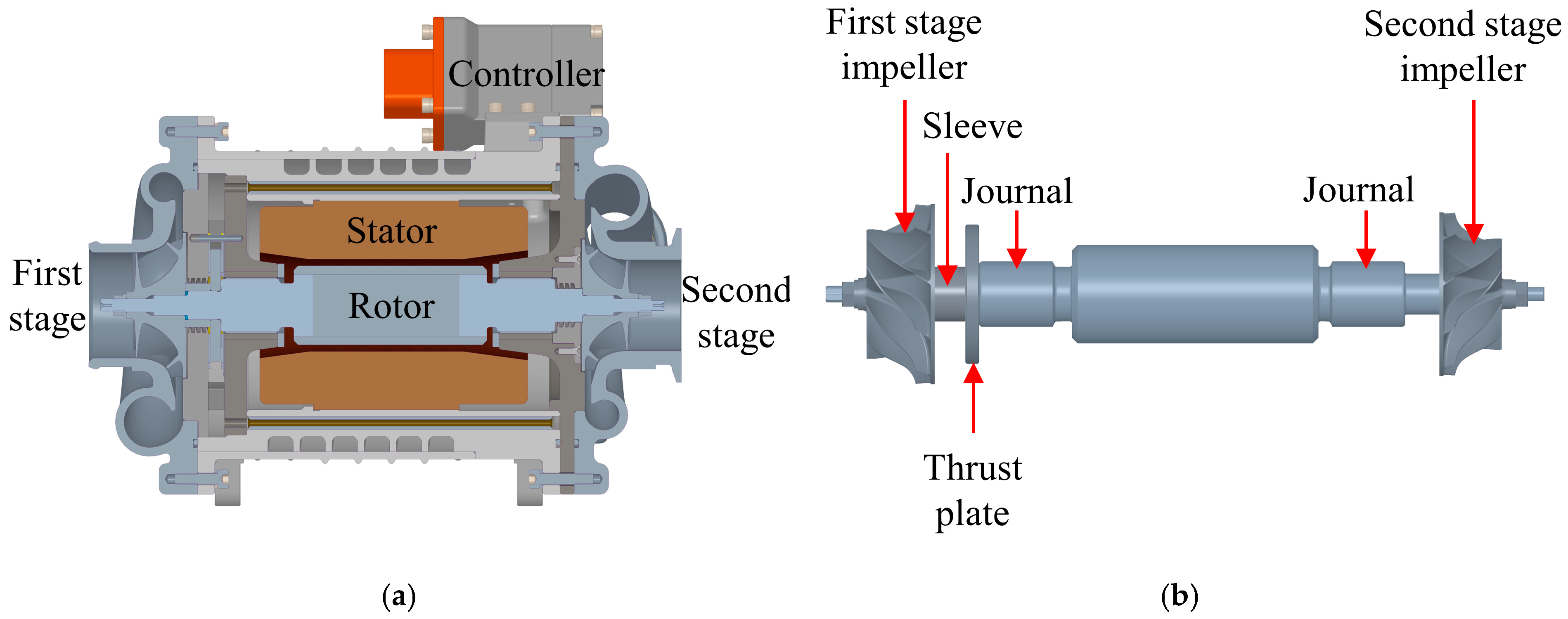
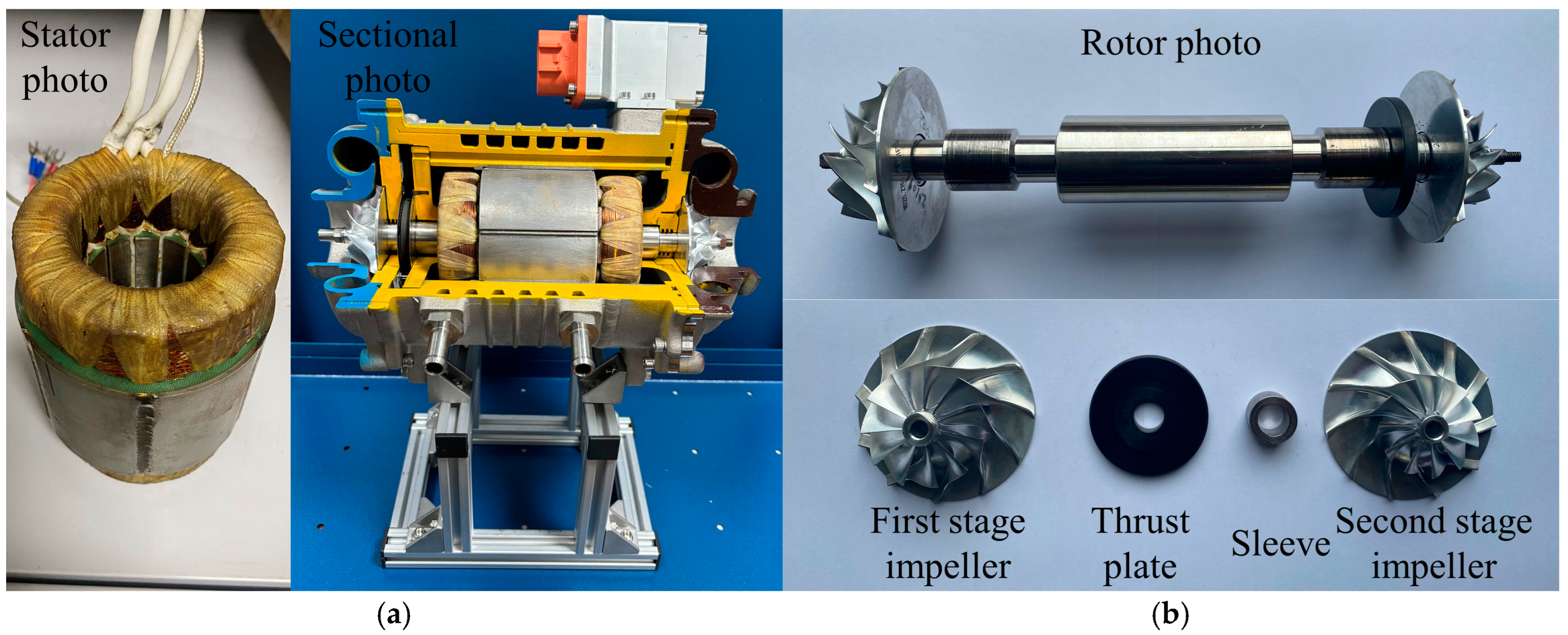
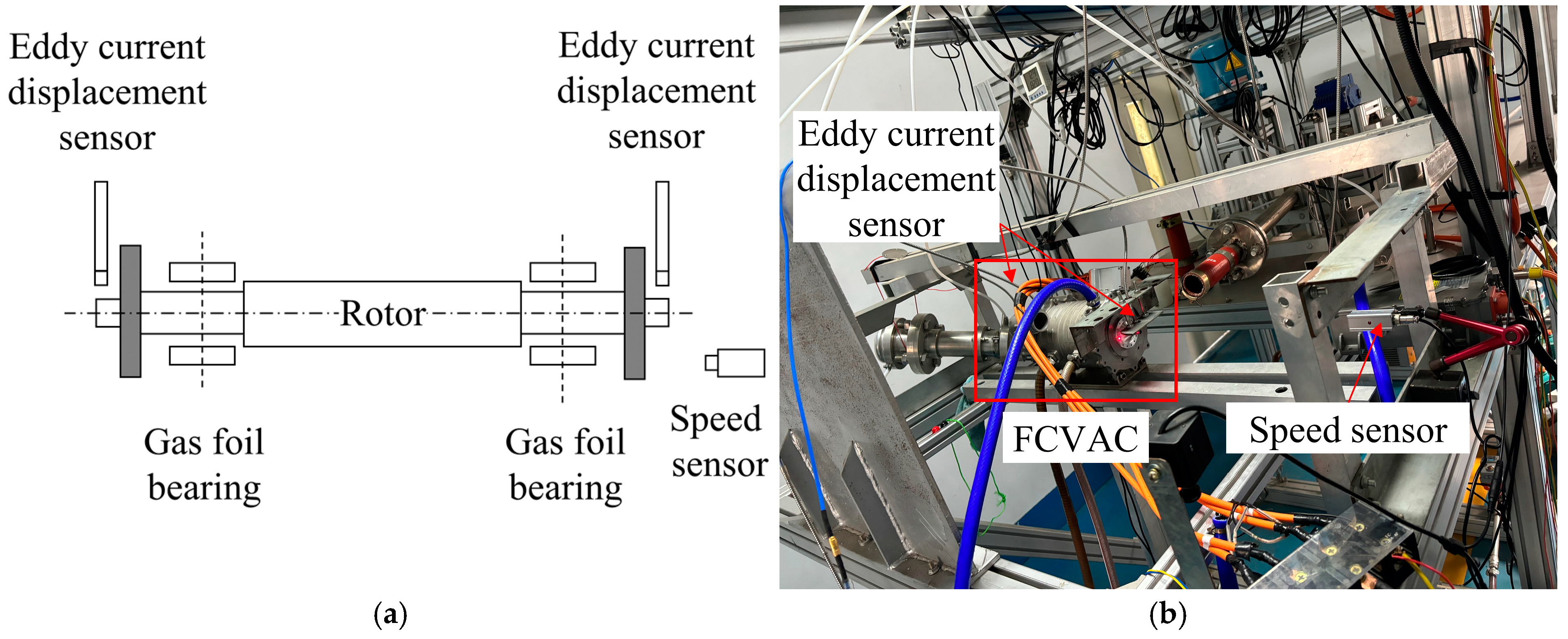
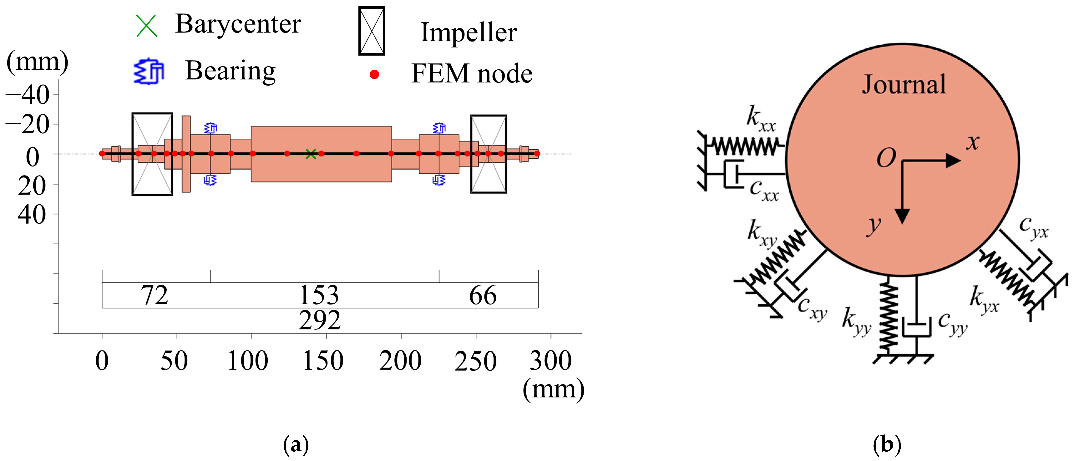
2.1. Test Rig Description

The structure of the HFCVAC used to build the test rig is shown in Figure 2. The test rig in this paper is modified by a commercial HFCVAC, which is designed to supply air to a hydrogen fuel cell bus. The compressor is driven by a permanent magnet synchronous motor with a rated power of 30 kW and a rated speed of 90 kRPM. The middle part of the rotor of the compressor has a built-in permanent magnet, and the rotor is fitted with a first-stage impeller, a second-stage impeller, a thrust disk, and a sleeve, which are fixed to the shaft by nuts at both ends of the shaft. The rotor Is supported radially by a pair of two-pad journal GFBs and axially by a pair of thrust GFBs to ensure its completely oil-free character.
The main parameters of the HFCVAC used for the test rig are listed in Table 1.
Figure 3 shows the schematic diagram and photo of the unbalance response test rig of HFCVAC. The rig is equipped with two eddy current displacement sensors to measure vertical displacement at both ends of the rotor. These sensors are fixed to the housing of the HFCVAC to minimize the influence of base vibrations. A photoelectric speed sensor is used to determine the phase of the displacement. The test impeller is marked with a black indicator, and the photoelectric speed sensor generates a low-level signal when the rotor reaches a specific angle of the mark.
To facilitate the addition of unbalanced masses without altering the structure of the original rotor, a test impeller was fabricated with the same mass and radial moment of inertia as the centrifugal impeller, as shown in Figure 4. The test impeller does not feature impeller blades and includes threaded holes for easy installation of unbalanced masses.

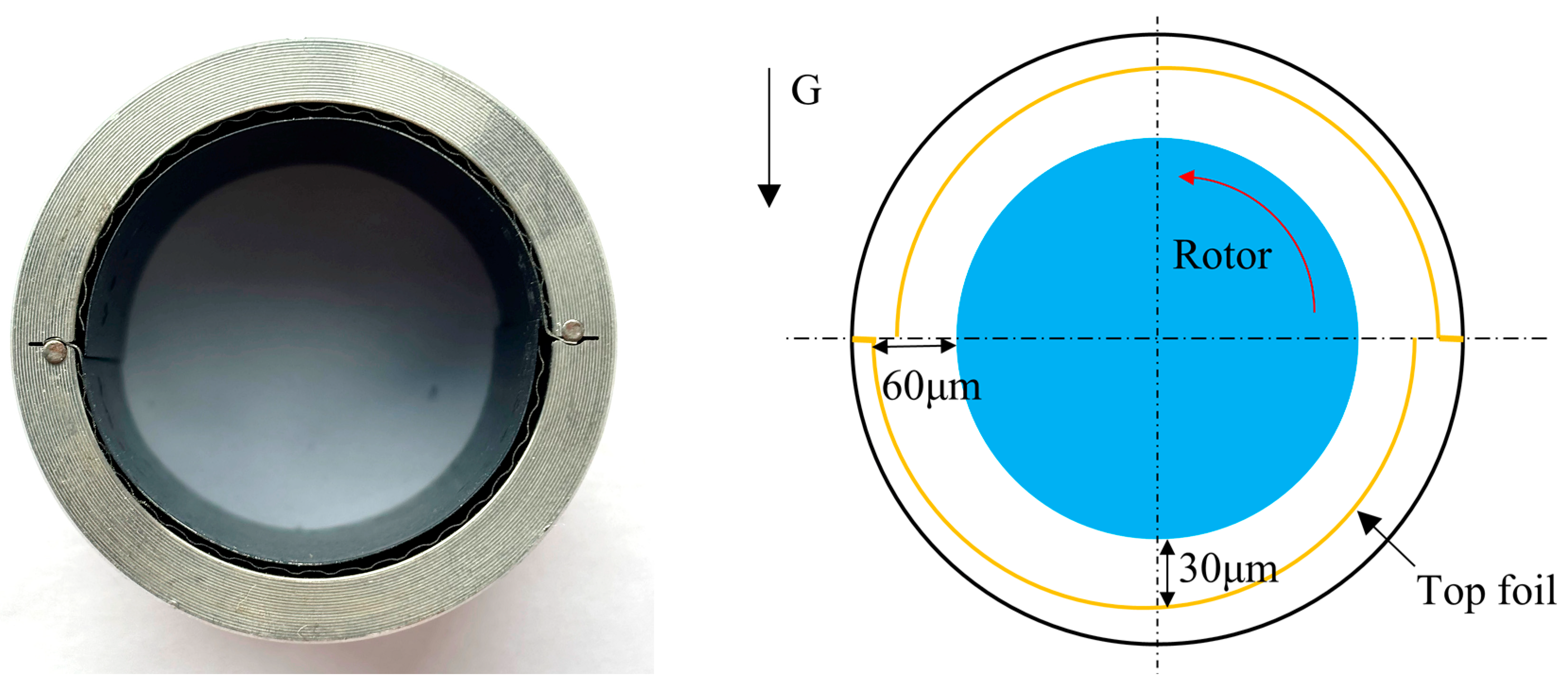
2.2. Specifications of Gas Foil Bearings

Figure 5 shows the two-pad GFB used in the experiments. This design consists of two bump foils and two top foils, which reduces the number of foils, thus lowering the fabrication and processing costs while retaining the advantages of the three-pad GFB with multiple gas films. Previous experiments have demonstrated that the two-pad GFB exhibits good load-carrying capacity and stability [18].
The key parameters of the two-pad GFBs used for the experiment are listed in Table 2.

2.3. Experimental Procedure

The experiments were conducted by accelerating the motor to a predetermined rotational speed, after which the power supply was disconnected, allowing the rotor to coast freely while displacement signals were recorded. Eddy-current displacement sensors were employed to measure rotor vibrations at both ends. The recorded displacement signals were processed using Fast Fourier Transform to generate waterfall plots illustrating the amplitude, frequency, and rotational speed relationship clearly. During each test, cooling fans were used to maintain sensor stability and accuracy, and a sufficient waiting period was observed between successive measurements to ensure consistent thermal and mechanical conditions.
Two distinct sets of unbalance experiments were performed:
(1)
Unilateral Unbalanced Mass Experiments
Four experimental tests were carried out with different unilateral unbalanced masses: no added mass, 79 mg, 118 mg, and 197 mg. The unbalanced mass was attached to the first-stage test impeller, with its angular position (phase) remaining consistent across all experiments. Displacement signals were systematically collected over the full range of rotational speeds according to this established procedure.
(2)
Bilateral Unbalanced Mass Experiments
Although the ISO 1940 standard [19] specifies allowable residual unbalance magnitudes, it does not clearly define the optimal distribution phase of the unbalanced mass across the rotor. To investigate the influence of phase distribution on rotor vibration, an additional experiment was conducted. In this scenario, the total unbalanced mass was maintained at 79 mg and was equally divided between the two impeller planes, resulting in 39.5 mg per plane—a method consistent with conventional double-sided dynamic balancing practices commonly employed in engineering. By systematically varying the phase difference between the unbalanced masses on the two impeller planes, displacement measurements were collected at both rotor ends across the operational speed range.
The selection of unbalanced masses was guided by established dynamic balancing standards and practical engineering considerations. According to ISO 1940 [19], the permissible residual unbalance can be calculated by:
U per = e per m
where Uper is the numerical value of the permissible residual unbalance; eper is the numerical value of the selected balance quality grade; and m is the numerical value of the total rotor mass.
The ISO 1940 standard recommends a balance quality grade for centrifuges of G6.3. Given the rotor’s rated operating speed of 90,000 RPM, the corresponding permissible specific unbalance is approximately eper ≈ 0.7 g·mm/kg and the permissible residual unbalance is calculated is Uper = 0.7 × 1.72 ≈ 1.2 g·mm. Considering a balancing radius of 15 mm, the permissible mass unbalance corresponding to G6.3 quality is 1.2 g·mm/15 mm = 80 mg.
In this study, unbalanced masses of 79 mg, 118 mg, and 197 mg were chosen. The smallest mass (79 mg) closely matches the calculated permissible unbalance for a new or well-balanced rotor (G6.3). The higher masses (118 mg and 197 mg) simulate progressively deteriorated balancing conditions, which commonly occur in practical operation due to factors such as dust accumulation, component wear, or mechanical degradation over time.
Prior to conducting the unbalance response experiments, the rotor was dynamically balanced, with the residual unbalanced mass strictly controlled within 3 mg. This ensured that the residual imbalance was negligible compared to the intentionally introduced test masses.

3. Theoretical Modeling of the GFB-Rotor System

To analyze the reasons behind the changes in the unbalance response of the GFB system, a model of the GFB-rotor system is developed in this paper. The analysis of the GFB-rotor system can be broadly categorized into linear and nonlinear approaches. Nonlinear analysis is a high-precision method for studying the GFB-rotor system, but its main drawback is the significant consumption of computational resources. The computational time required for nonlinear analysis can be tens or even hundreds of times greater than that for linear analysis with the same computational resources. Hoffmann et al. [20] found that the stability results predicted by the linearized force coefficient method closely match those obtained using the nonlinear method, and Gu et al. [21] reached the same conclusion. Therefore, this paper adopts the linearized dynamic coefficient method to analyze the GFB-rotor system.

3.1. Rotor Dynamics Model

Figure 6 shows the model of the GFB-rotor system. The rotor is modeled using the Finite Element Method (FEM) with beam units that account for shear force, and the gyroscopic effect is also considered. The rotor model, including the gyroscopic effects, can be described as [22]:
M U ¨ + ( ω G + C ) U ˙ + K U = Q
where M is the mass matrix; G is the gyro matrix; C is the damping matrix; K is the stiffness matrix; ω is the rotor angular velocity; U is the rotor nodal displacement vector; and Q is the nodal load vector.
The force-displacement model of the GFB acting on the rotor is given by:
[ F x F y ] = [ k x x k x y k y x k y y ] [ X Y ] + [ c x x c x y c y x c y y ] [ X ˙ Y ˙ ]
The rotor dynamics calculations were performed using the MATLAB R2024a program released by Friswell [22].

3.2. Reynolds Equation

The dimensionless form Reynolds equation of thin-film lubrication for an isothermal, compressible fluid in cylindrical coordinates is:
θ ( p ¯ H ¯ 3 p ¯ θ ) + z ¯ ( p ¯ H ¯ 3 p ¯ z ¯ ) = Λ ( p ¯ H ¯ ) θ + 2 Λ γ ( p ¯ H ¯ ) t ¯
where p ¯ is the dimensionless gas film pressure; z ¯ is the dimensionless axial coordinate; H ¯ is the dimensionless gas film height; Λ is the bearing number; γ is the excitation frequency ratio; and dimensionless time t ¯ is expressed as:
p ¯ = p p a , z ¯ = z R , H ¯ = H C , Λ = 6 μ 0 ω p a ( R C ) 2 , γ = ω e ω , t ¯ = ω e t
where p is the gas film pressure; pa is the reference pressure; z is the axial coordinate; R is the journal radius; H is the gas film thickness; C is the nominal clearance; μ0 is the gas dynamic viscosity; ωe is the excitation frequency; and t is time.
The gas film thickness H can be expanded as:
H = C + e cos ( θ θ 0 ) + δ
where e is the eccentricity; θ0 is the attitude angle; and δ is the top foil deformation.
The Reynolds equation is solved using the finite difference method. The rotordynamic coefficients are solved using the perturbation method [23]. The corresponding solution program was written in MATLAB.

3.3. Foil Structure Modeling

The bump foil structure is modeled as spring stiffness coefficients and a viscous damping coefficient. The relationship between the structural deformation of the foil and the gas film pressure is:
p p a = K f δ + C f d δ d τ
where the foil structural stiffness coefficient Kf and the viscous damping coefficient Cf are expressed as:
K f = k b + k t ,   C f = η γ k b
where η is the structural loss factor; kb is the bump foil structural stiffness; and kt is the top foil structural stiffness. In this study, the top foil stiffness kt is modeled using the Mindlin plate, and the bump foil stiffness kb is calculated by [24]:
k b = 2 s l 3 ( 1 v b 2 ) E b t b 3
where s is the bump foil pitch; l is the bump half-length; vb is the Poisson’s ratio; Eb is the elastic modulus; and tb is the thickness of the bump foil.

4. Results and Discussion

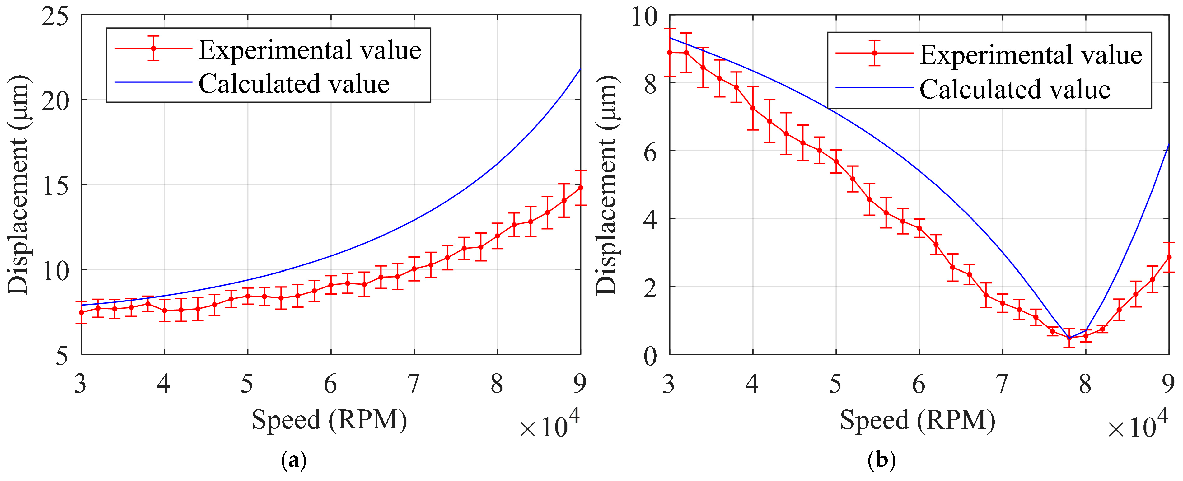
4.1. Model Validation

Figure 7 shows the flow chart of the model validation. The unbalance response results from the model in this paper are compared with experimental data to verify the accuracy of the model.
Figure 8 shows the experimentally measured displacements of the rotor with 79 mg of unbalanced mass added to the first-stage test impeller, alongside the model-predicted results. The trend predicted by the model aligns well with the experimental results, though the predicted displacements are slightly larger. At 30,000 RPM, the error between the model calculation results and the experimental data is less than 5%. This discrepancy arises because the model uses the dynamic coefficients of the bearing when the rotor is in an equilibrium position. As the rotor’s displacement increases, the gas film between the rotor and the bearing becomes thinner, which in turn increases the stiffness provided by the gas film. As a result, the rotor’s displacement decreases compared to the original calculation based on gas film stiffness.

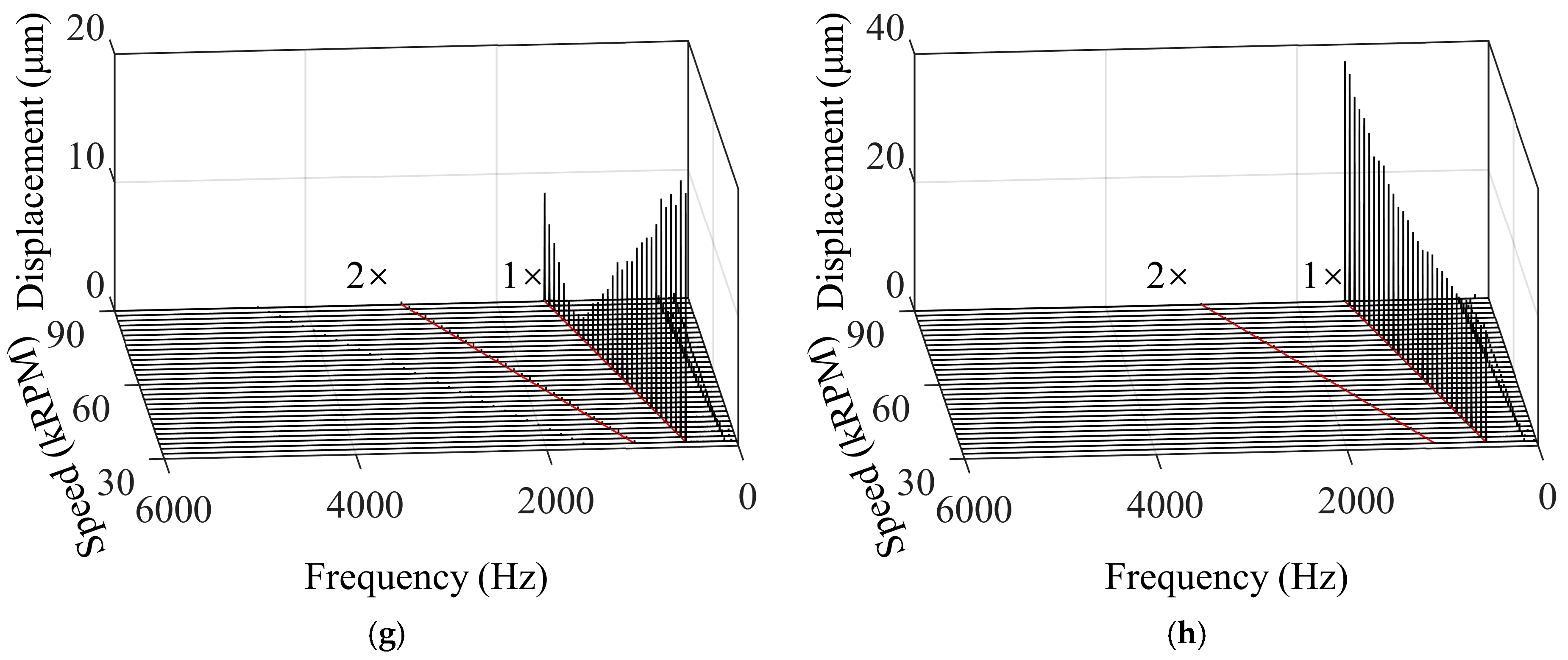
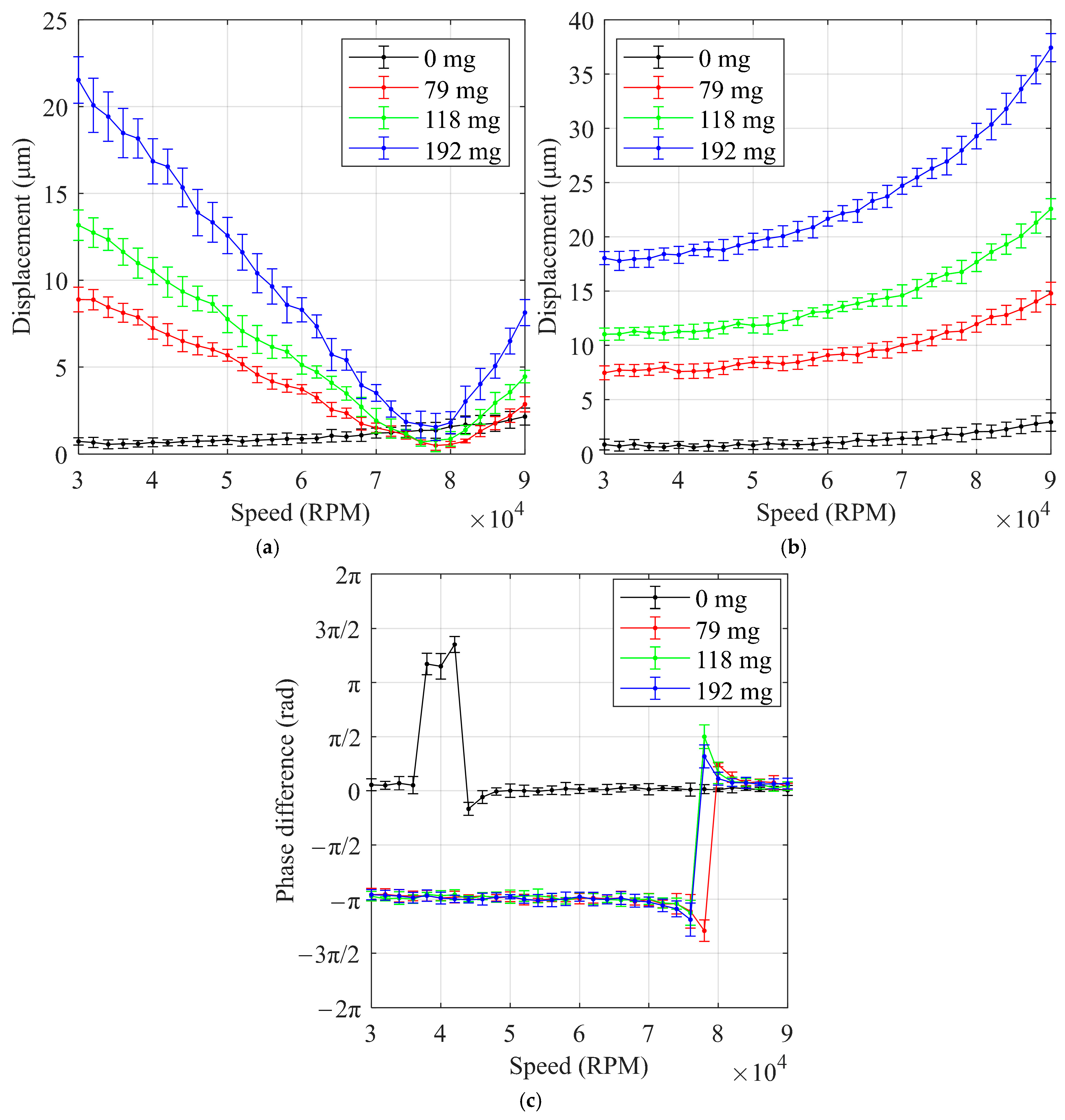
4.2. Unilateral Unbalanced

The collected signals were subjected to Fast Fourier Transform and the resulting waterfalls are shown in Figure 9. The primary displacement component was found at 1× RPM, which corresponds to the synchronous vibration caused by the unbalanced mass. A secondary component appeared at 2× RPM, likely due to slight misalignment of the rotor. The subsynchronous vibrations in the low-frequency range were minimal, indicating that the GFBs exhibited good stability during the experiments. Previous research indicates that multi-pad foil bearings with appropriate preload effectively suppress subsynchronous vibrations [25]. Thus, the minimal subsynchronous vibration in our experiments is attributed primarily to the two-pad GFB’s preloaded structure, a feature known to enhance rotor stability even under substantial unbalanced loads.
The 1× RPM component is the primary source of vibration. The displacement at this frequency was isolated for further comparison. The relationship between the 1× RPM displacement and rotational speed is shown in Figure 10. It can be observed that, after the unbalanced mass was installed, the displacement trends at the two ends of the rotor diverged with increasing speed. On the first-stage side, the displacement initially decreased with speed, then increased; on the second-stage side, the displacement monotonically increased, with the growth rate accelerating. The phase difference between the two sides of the rotor changed abruptly between 70,000 and 80,000 RPM, transitioning from an inverted phase to a synchronized phase. The displacement increase on the second-stage side follows the general trend that centrifugal force from the unbalanced mass is proportional to the square of the rotational speed. The decrease in displacement on the first-stage side requires further investigation.
Figure 11 presents the Campbell diagram of the GFB-rotor system of the HFCVAC. At low speeds, the rotor exhibits conical and cylindrical modes, while at higher speeds, bending modes are observed. The frequency of the bending critical speed for the rotor in this study is 2083 Hz, and the corresponding critical speed is 60 × 2083 = 124,980 RPM. The rated speed of the HFCVAC in this paper is 90,000 RPM, which maintains a 25% separation margin between their operating speeds and their critical speeds [26].
Figure 12 shows the ODSs of the rotor with 79 mg of unilateral unbalanced mass installed, as calculated by the model. The arrows indicate the direction of rotor displacement. These ODSs help explain how displacement changes with speed. At low speeds, the rotor’s ODS is a result of the superposition of rigid body motion and conical modes. As speed increases, the rotor’s ODS gradually transitions to a “U”-shaped bending mode. On the first-stage side of the rotor, the bending mode counteracts the displacement caused by the rigid body and conical modes, resulting in a reduction in rotor displacement. The phase difference between the displacements before and after this change is π, which is consistent with the phase difference observed in the experimental results. This explains the phenomenon where the displacement of the rotor end decreases and then increases after the addition of unilateral unbalanced mass.

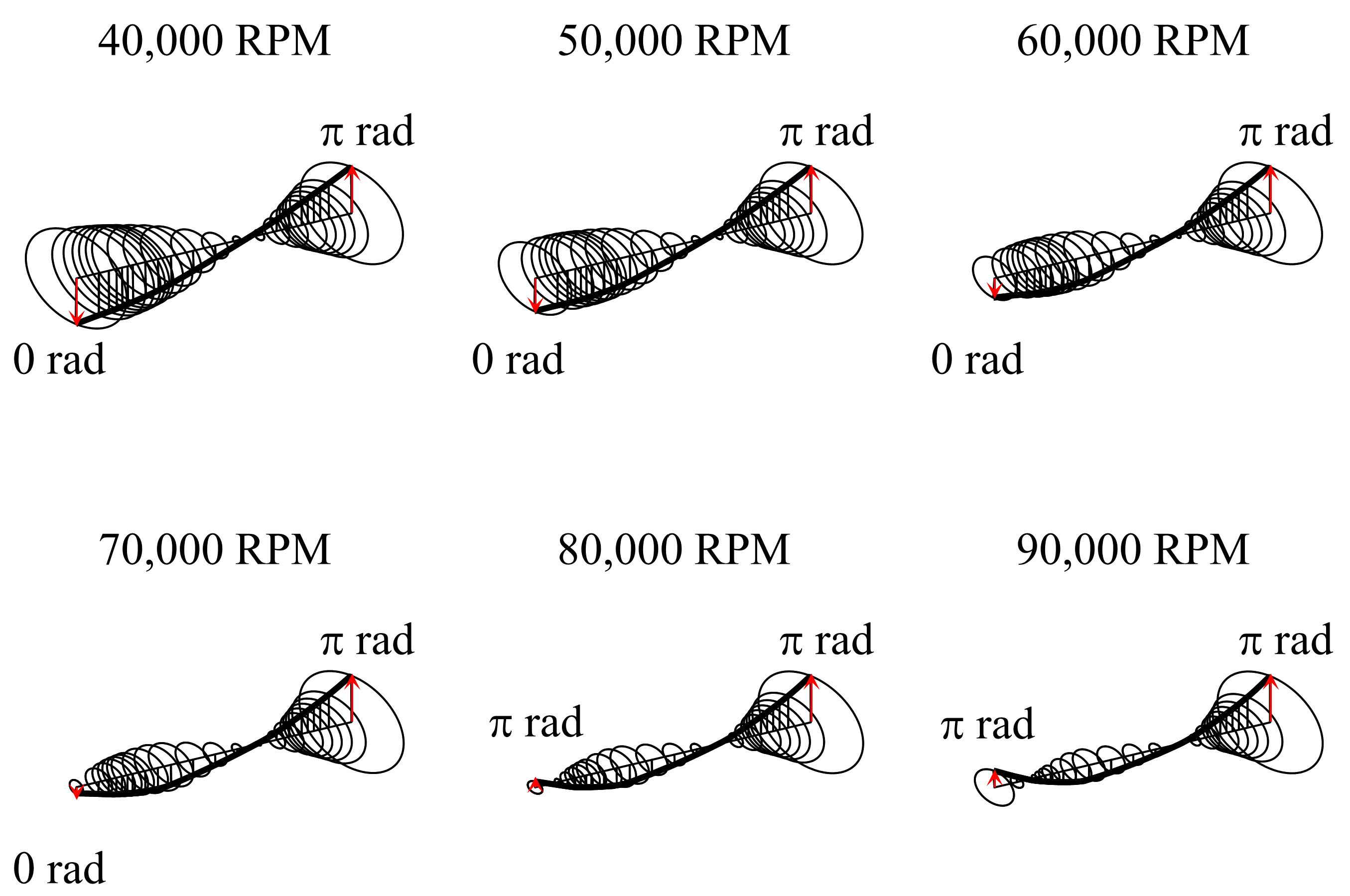
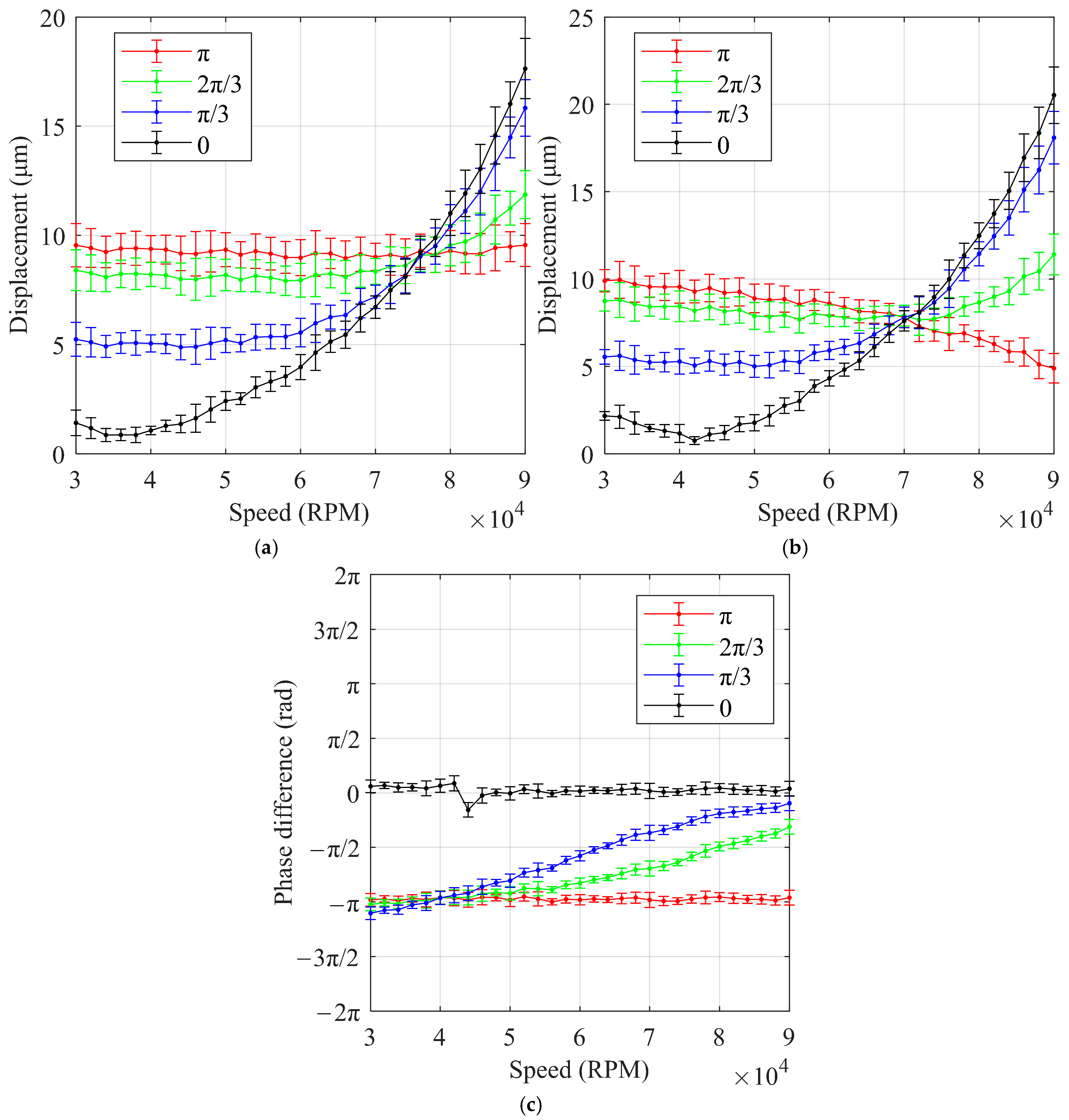
4.3. Bilateral Unbalanced

As shown in Figure 13, the experimental results show that at high speeds (greater than 80,000 RPM), larger phase differences between the unbalanced masses resulted in smaller displacements. Conversely, at low speeds (less than 70,000 RPM), smaller phase differences led to smaller displacements. At a phase difference of 0, the displacement at around 40,000 RPM was close to 1 µm, which is a very small displacement for an unbalanced mass of 79 mg. These findings suggest that for the rotor structure of the HFCVACs, a rational distribution of the unbalanced mass phase can significantly reduce rotor displacement, even with a large unbalanced mass, at specific rotational speeds.
Figure 14 shows the variation of the ODSs of the rotor with 79 mg bilateral unbalanced mass installed. Like the unilateral unbalanced mass case, the rotor transitions from a rigid mode to a bending mode as the speed increases. However, the speed at which this transition occurs depends on the phase difference of the unbalanced mass distribution. For unbalanced masses with the same phase, the rotor displacement shifts from rigid to bending mode dominance at lower speeds. In contrast, when the unbalanced masses are in different phases, this transition occurs at a higher speed. A larger phase difference between the unbalanced masses increases the rotational speed required for the bending mode to become dominant. In-phase unbalanced masses stimulate the bending mode earlier because the rotor’s structure—primarily concentrated in the permanent magnet at the rotor’s center and the impellers at both ends—supports bending modes. The direction of the force generated by in-phase unbalanced masses aligns with that of the bending mode. As a result, in-phase unbalanced masses can more effectively use the rotor’s bending modes to counteract the displacement caused by rigid translational modes, leading to less vibration at lower speeds.

5. Conclusions

In this paper, the response of the rotor of an HFCVAC to the unbalanced mass is experimentally investigated by setting up a test rig for the unbalance response of a GFB-rotor system based on an HFCVAC, and a model of the GFB-rotor system is established to explain the observed changes in the unbalance response. The main conclusions of this study are as follows:
(1)
For the HFCVAC studied, the influence of unbalanced mass on subsynchronous vibration is relatively small. Adding unilateral unbalanced mass causes the synchronous vibration on that side of the rotor to decrease and then increase with speed. In contrast, synchronous vibration on the opposite side continuously increases with speed. When bilateral equal unbalanced masses are added, synchronous vibration on each side increases at low speeds with the phase difference of the unbalanced mass, while the opposite trend is observed at high speeds.
(2)
For high-speed compressors, rotor bending mode significantly affects vibration. This bending causes the rotor’s vibration amplitude to change nonlinearly with speed, even though the rated speed still maintains a sufficient separation margin from the first bending critical speed.
(3)
With double-face dynamic balancing of the compressor rotor, the phase of the unbalanced mass needs to be reasonably distributed according to the operating speed. Different optimal phase differences of unbalanced mass distribution exist for low-speed and high-speed compressors.

Author Contributions

Conceptualization, M.Y.; Data curation, M.Y.; Formal analysis, M.Y.; Investigation, M.Y.; Methodology, M.Y.; Resources, X.L.; Software, M.Y.; Validation, M.Y.; Visualization, M.Y.; Writing—original draft, M.Y.; Writing—review and editing, X.L. All authors have read and agreed to the published version of the manuscript.

Funding

This research received no external funding.

Data Availability Statement

The original contributions presented in this study are included in the article. Further inquiries can be directed to the corresponding author.

Conflicts of Interest

The authors declare no conflicts of interest.

Abbreviations

The following abbreviations are used in this manuscript:
HFCVACHydrogen Fuel Cell Vehicle Air Compressor
GFBGas Foil Bearing
FEMFinite Element Method
ODSOperational Deflection Shape

References

  1. Pramuanjaroenkij, A.; Kakaç, S. The fuel cell electric vehicles: The highlight review. Int. J. Hydrogen Energy 2023, 48, 9401–9425. [Google Scholar] [CrossRef]
  2. Pattnayak, M.R.; Ganai, P.; Pandey, R.K.; Dutt, J.K.; Fillon, M. An overview and assessment on aerodynamic journal bearings with important findings and scope for explorations. Tribol. Int. 2022, 174, 107778. [Google Scholar] [CrossRef]
  3. Wu, Y.; Bao, H.; Fu, J.; Wang, X.; Liu, J. Review of recent developments in fuel cell centrifugal air compressor: Comprehensive performance and testing techniques. Int. J. Hydrogen Energy 2023, 48, 32039–32055. [Google Scholar] [CrossRef]
  4. Larsen, J.S.; Santos, I.F. On the nonlinear steady-state response of rigid rotors supported by air foil bearings—Theory and experiments. J. Sound Vib. 2015, 346, 284–297. [Google Scholar] [CrossRef]
  5. von Osmanski, S.; Larsen, J.S.; Santos, I.F. A fully coupled air foil bearing model considering friction—Theory & experiment. J. Sound Vib. 2017, 400, 660–679. [Google Scholar] [CrossRef]
  6. Guo, Z.; Cao, Y.; Feng, K.; Guan, H.; Zhang, T. Effects of Static and Imbalance Loads on Nonlinear Response of Rigid Rotor Supported on Gas Foil Bearings. Mech. Syst. Signal Process. 2019, 133, 106271. [Google Scholar] [CrossRef]
  7. Baum, C.; Leister, T.; Seemann, W. Stability and bifurcation analysis of a rotor in rigid and foil air bearings utilized for the identification of the air whirl effect. J. Sound Vib. 2022, 536, 117067. [Google Scholar] [CrossRef]
  8. Guan, H.; Li, J.; Wei, K.; Zou, H. Rotordynamics of a rotor radially and axially supported by active bump-type foil bearings and bump-type thrust foil bearings. Mech. Syst. Signal Process. 2024, 208, 110995. [Google Scholar] [CrossRef]
  9. Hu, B.; Yang, X.; Hou, A.; Wang, R.; Wu, Z.; Ni, Q.; Li, Z. Nonlinear Dynamic Responses of Rigid Rotor Supported by Thick Top Foil Bearings. Lubricants 2023, 11, 453. [Google Scholar] [CrossRef]
  10. Kumar, P. Dynamic analysis and identification in a cracked and unbalanced rigid rotor with two offset discs and one middle disc mounted on foil bearings. Int. J. Dynam. Control 2024, 12, 2648–2673. [Google Scholar] [CrossRef]
  11. Xu, H.; Shao, C.; Yang, B.; An, Q. Numerical investigation on the rotordynamics of a high-speed air compressor supported by gas foil bearings. Proc. Inst. Mech. Eng. Part C J. Mech. Eng. Sci. 2024, 238, 5580–5596. [Google Scholar] [CrossRef]
  12. Zhang, L.; Zhang, X.; Xu, H. Theoretical and experimental study on the effect of adjustable journal bearings on the vibration response of rigid and slender rotor systems. Mech. Syst. Signal Process. 2025, 224, 111951. [Google Scholar] [CrossRef]
  13. Heshmat, H. Operation of foil bearings beyond the bending critical mode. J. Tribol.-Trans. ASME 2000, 122, 192–198. [Google Scholar] [CrossRef]
  14. Ying, M.; Liu, X.; Zhang, Y.; Zhang, C. Impact of Gas Foil Bearings, Labyrinth Seals, and Impellers on the Critical Speed of Centrifugal Compressors for Fuel Cell Vehicles: A Comprehensive Investigation. Lubricants 2023, 11, 532. [Google Scholar] [CrossRef]
  15. Chen, S.; Zuo, S.; Wu, Z.; Liu, C. Comprehensive vibro-acoustic characteristics and mathematical modeling of electric high-speed centrifugal compressor surge for fuel cell vehicles at various compressor speeds. Mech. Syst. Signal Process. 2022, 178, 109311. [Google Scholar] [CrossRef]
  16. Shi, T.; Chen, Q.; Peng, X.; Feng, J.; Guo, Y. Multi-objective optimization of the oil-free centrifugal air compressor in hydrogen fuel cell vehicles based on grey relational analysis. Int. J. Hydrogen Energy 2023, 48, 26341–26355. [Google Scholar] [CrossRef]
  17. Zhao, Y.; Liu, Y.; Liu, G.; Yang, Q.; Li, L.; Gao, Z. Air and hydrogen supply systems and equipment for PEM fuel cells: A review. Int. J. Green Energy 2022, 19, 331–348. [Google Scholar] [CrossRef]
  18. Ying, M.; Liu, X.; Zhang, C.; Wang, X.; Liu, Y.; Zhang, Y. The Two-Pad: A Novel Gas Foil Bearing for Fuel Cell Vehicles. Int. J. Energy Res. 2023, 2023, 5521171. [Google Scholar] [CrossRef]
  19. ISO 1940-1; Mechanical Vibration—Balance Quality Requirements for Rotors in a Constant (Rigid) State—Part 1: Specification and Verification of Balance Tolerances. ISO: Geneva, Switzerland, 2003.
  20. Hoffmann, R.; Pronobis, T.; Liebich, R. Non-linear stability analysis of a modified gas foil bearing structure. In Proceedings of the 9th IFToMM International Conference on Rotor Dynamics; Springer: Berlin/Heidelberg, Germany, 2015; pp. 1259–1276. [Google Scholar]
  21. Gu, Y.; Ren, G.; Zhou, M. A Novel Method for Calculating the Dynamic Force Coefficients of Gas Foil Bearings and Its Application in the Rotordynamic Analysis. J. Sound Vib. 2021, 515, 116466. [Google Scholar] [CrossRef]
  22. Friswell, M.I.; Penny, J.E.T.; Garvey, S.D.; Lees, A.W. Dynamics of Rotating Machines, 1st ed.; Cambridge University Press: Cambridge, UK, 2010. [Google Scholar] [CrossRef]
  23. Lund, J.W. Calculation of Stiffness and Damping Properties of Gas Bearings. J. Lubr. Technol. 1968, 90, 793–803. [Google Scholar] [CrossRef]
  24. Heshmat, H.; Walowit, J.A.; Pinkus, O. Analysis of Gas Lubricated Compliant Thrust Bearings. J. Lubr. Technol. 1983, 105, 638–646. [Google Scholar] [CrossRef]
  25. Zywica, G.; Baginski, P.; Bogulicz, M.; Martowicz, A.; Roemer, J.; Kantor, S. Numerical identification of the dynamic characteristics of a nonlinear foil bearing structure: Effect of the excitation force amplitude and the assembly preload. J. Sound Vib. 2022, 520, 116663. [Google Scholar] [CrossRef]
  26. ANSI/HI 9.6.8; Rotodynamic Pumps—Guideline for Dynamics of Pumping Machinery. American National Standards Institute, Hydraulic Institute: Parsippany, NJ, USA, 2014.
Figure 1. A typical HFCVAC: (a) sectional view; (b) rotor structure.
Lubricants 13 00181 g001
Figure 2. HFCVAC used for the test rig: (a) sectional photo; (b) rotor photo.
Lubricants 13 00181 g002
Figure 3. Test rig: (a) scheme diagram; (b) photo.
Lubricants 13 00181 g003
Figure 4. Test impeller: (a) top view; (b) with unbalanced mass installed.
Lubricants 13 00181 g004
Figure 5. Two-pad journal GFB used for the experiment.
Lubricants 13 00181 g005
Figure 6. Model of GFB-rotor system: (a) rotor FEM model; (b) GFB dynamic coefficient model.
Lubricants 13 00181 g006
Figure 7. Flow chart of the model validation.
Lubricants 13 00181 g007
Figure 8. Comparison of experimental results and calculation results: (a) first-stage side; (b) bearing second-stage side.
Lubricants 13 00181 g008
Figure 9. Displacement of the rotor after installing an unbalanced mass at the first-stage impeller: (a) 0 mg—first-stage side; (b) 0 mg—second-stage side; (c) 79 mg—first-stage side; (d) 79 mg—second-stage side; (e) 118 mg—first-stage side; (f) 118 mg—second-stage side; (g) 197 mg—first-stage side; (h) 197 mg—second-stage side.
Lubricants 13 00181 g009aLubricants 13 00181 g009b
Figure 10. 1× RPM displacement after installing an unbalanced mass at the first-stage impeller: (a) first-stage side; (b) second-stage side; (c) phase difference.
Lubricants 13 00181 g010
Figure 11. Campbell diagram of the HFCVAC.
Lubricants 13 00181 g011
Figure 12. ODSs of the rotor with 79 mg unilateral unbalanced mass installed.
Lubricants 13 00181 g012
Figure 13. 1× RPM displacement after installing unbalanced mass on both sides: (a) first-stage side; (b) second-stage side; (c) phase difference.
Lubricants 13 00181 g013
Figure 14. ODSs of the rotor with 79 mg bilateral unbalanced mass installed.
Lubricants 13 00181 g014
Table 1. Main parameters of the HFCVAC used for the test rig.
ParametersValues
Rated power30 kW
Rated speed90 kRPM
Idle speed30 kRPM
Rotor mass1443 g
Thrust plate mass122 g
Sleeve mass17 g
Total rotor length292 mm
Journal bearing center span153 mm
First-stage impeller mass79 g
First-stage impeller radial moment of inertia18.4 kg·mm2
Second-stage impeller mass56 g
Second-stage impeller radial moment of inertia11.2 kg·mm2
Table 2. Key parameters of the two-pad GFBs used for the experiment.
ParametersValues
Bearing diameter25 mm
Bearing width25 mm
Nominal clearance30 μm
Preload30 μm
Top foil thickness0.1 mm
Bump foil thickness0.1 mm
Bump pitch3.17 mm
Bump half length1.27 mm
Poisson’s ratio0.29
Modulus of elasticity214 GPa
Disclaimer/Publisher’s Note: The statements, opinions and data contained in all publications are solely those of the individual author(s) and contributor(s) and not of MDPI and/or the editor(s). MDPI and/or the editor(s) disclaim responsibility for any injury to people or property resulting from any ideas, methods, instructions or products referred to in the content.

