Abstract
Anisotropic microstructures and wear resistance are caused by large thermal gradients during selective laser melting (SLM). Investigating the wear resistance in different planes of SLM specimens is crucial. Hence, the effect of heat treatment on the anisotropy of the microstructure, density, microhardness, and wear resistance of SLM 316L stainless steel was studied. Specimens subjected to solution + aging treatment exhibited γ austenite and α ferrite phases with lower microstrain, as determined via X-ray diffraction (XRD) analysis. Microstructure observations demonstrated that SLM 316L appears as intersecting melt pools on the XOY plane and fish scale-like melt pools on the XOZ plane. After heat treatment, the melt boundaries disappeared, carbides (M23C6) precipitated at grain boundaries and within the grains, and the microstructures coarsened and became more uniform. The microhardness and wear resistance of the XOY plane were shown to be superior to those of the XOZ plane, and the microhardness decreased following heat treatment. Compared with SLM 316L, the microhardness of the XOY and XOZ planes of the specimen subjected to solution + aging treatment decreased by 5.96% and 4.98%. The friction and wear test results revealed that the specimen after solution + aging treatment had the lowest friction coefficient and the smallest wear rate. The wear rates of specimens from the XOY and XOZ planes after solution + aging treatment were 21.1% and 27.1% lower than that of SLM 316L, exhibiting the best wear resistance.
1. Introduction
Metal additive manufacturing [1] is a manufacturing process based on three-dimensional models that uses lasers, electron beams, electric arcs, and other heat sources to melt metal powders and build parts through layer-by-layer accumulation of materials. Metal additive manufacturing offers significant advantages over conventional fabrication techniques, including near net shape forming capabilities and high design flexibility for customized components [2,3]. It is currently widely used in industrial applications such as the aerospace industry [4], biomedical equipment [5], and automotive manufacturing [6]. Among these metal additive manufacturing methods, selective laser melting (SLM) technology has emerged as a research focus [7,8]. Therefore, SLM technology has been developed to fabricate 316L stainless steel due to the good formability, low carbon content, and high laser absorption of its spherical powder [9]. The microstructure determines the mechanical properties. Improvements in mechanical properties primarily stem from the finer columnar and cellular crystals that result from the significant temperature gradients and rapid solidification characteristics associated with the high cooling rates [10] of SLM technology. Several studies [11,12,13] have focused on 316L austenitic stainless steel fabricated using SLM, which exhibits superior mechanical properties than conventionally manufactured 316L. Therefore, most studies still focus on microstructure and mechanical properties. Bakhtiarian et al. [14] reported the density, microhardness, and mechanical properties of SLM 316L and optimized process parameters using the Taguchi optimization method. It was found that 316L with a tensile strength of 649 MPa, a yield strength of 409 MPa, and an elongation of 42% was obtained using a laser power of 180 W, a scanning speed of 1200 mm/s, and a layer thickness of 0.03 mm. Li et al. [15] studied the friction and wear properties of SLM 316L samples by optimizing the process parameters and found that the effect of laser power on the coefficient of friction (COF) and wear rate was not significant. Zhu and Hua et al. [16,17] found that the tribological properties of SLM 316L can be enhanced via grinding and polishing. Sun et al. [18] investigated the dry sliding wear behavior of SLM 316L stainless steel and found that the wear resistance of SLM 316L was inferior to that of 316L fabricated using conventional methods due to the lower density. Currently, research evaluating the tribological performance and wear mechanisms of SLM 316L specimens is limited.
SLM processes involving high temperatures and rapid melting and solidification often induce a variety of internal and surface defects [19,20,21], such as an inhomogeneous microstructure, porosity, microcracks, and residual stresses. Besides process parameter modification, heat treatment and surface modification technologies are introduced to reduce residual stresses [22,23] and other surface defects [24]. Heat treatment is more convenient than surface modification technologies, as the latter cause plastic deformation of the specimen surface. Zhang et al. [25] found that residual strain decreases with increasing solution temperature, but microhardness decreases with increasing temperature. After solution treatment at 1050 °C for 0.5 h, the specimen showed a significant reduction in residual strain while maintaining high hardness. Kong et al. [26] found that when applying solution treatment at 1050 °C for 2 h, the specimen maintained high strength while reducing anisotropy. Insufficient solution treatment time (less than 2 h) cannot significantly improve the anisotropic characteristics of the microstructure, while excessive duration may lead to excessive grain coarsening. Patrik et al. [27] found after artificial aging at 700 °C, M23C6 precipitates were observed, which may play a role in precipitation strengthening. Yin et al. [28] found that a lower aging temperature may promote the formation of brittle σ phase, while an excessively high temperature can result in microstructural coarsening. At 850 °C, aging primarily facilitates the precipitation of M23C6 carbides rather than brittle Cr2N nitrides. Excessive aging durations promote the coarsening of precipitates, while insufficient aging time may result in incomplete precipitation [29]. Nevertheless, it is inevitable that SLM 316L specimens exhibit anisotropy in their microstructure and other properties. Zhou et al. [30] investigated the microstructure anisotropy and the mechanical properties of SLM 316L. Their results showed that SLM 316L stainless steel exhibits both excellent strength and ductility; its mechanical properties demonstrate significant anisotropy caused by the geometric relationship between the boundary of the molten pool and the tensile force. Yang et al. [31] studied the wear resistance of SLM 316L stainless steel on different surfaces along six scratch directions and found that the anisotropic microstructures affect the wear resistance of different surfaces. Overall, the effect of heat treatment on the wear resistance of different building directions of SLM 316L stainless steel has been minimally investigated. To date, researchers have either studied the wear resistance of the top surface after heat treatment or the wear resistance of different SLM building directions.
In practical industrial applications, components may experience friction and wear from multiple directions. The rapid melting and layer-by-layer stacking characteristics of SLM lead to the anisotropy of the microstructure and residual stress, which may cause microcracks more easily during friction. Wear failure in different directions can lead to overall failure of the component, while heat treatment can reduce anisotropy and residual stress. Therefore, it is urgent to explore effective heat treatment processes to improve the wear resistance of various building directions at the same time. Hence, research on the effect of heat treatment on the anisotropy of friction and wear resistance of SLM 316L is essential. In this paper, SLM 316L fabricated via optimized process parameters was heat-treated with a solution treatment (1050 °C × 2 h), an aging treatment (850 °C × 4 h), and a solution (1050 °C × 2 h) + aging treatment (850 °C × 4 h). The effects of different heat treatment processes on the anisotropic wear resistance of selective laser-melted 316L stainless steel were studied. In addition, microstructure, microhardness, and density were also studied to explain the changes in the wear resistance of specimens with different heat treatment processes. This study provides a theoretical basis for exploring the optimal heat treatment system to comprehensively improve the performance of 316L stainless steel and focuses on shortening the preparation cycle of industrial transmission components and extending their wear life.
2. Materials and Methods
2.1. Sample Preparation
In this study, 316L stainless steel was fabricated using a BLT-S210 metal printer (BLT, Shizuishan, China) equipped with a maximum 500 W fiber laser, with a wavelength of 1060~1080 nm and a laser spot diameter of 50~55 μm. The laser beam exhibited a Gaussian energy distribution with a laser beam quality factor (M2) of 1.1. During the SLM process, a building chamber with maximum dimensions of 105 (W) × 105 (D) × 200 (H) mm was filled with argon gas (purity: 99.99%) in order to reduce the oxygen concentration to below 200 ppm. SLM specimens with dimensions of 10 (W) × 10 (D) × 10 (H) mm were fabricated. Based on the commercial standard parameters provided by the SLM equipment manufacturer and our previous experiments, a laser power of 150 W, scanning speed of 800 mm/s, hatch spacing of 80 μm, and layer thickness of 20 μm were employed. The SLM specimens were prepared by rotating 67° layer by layer based on the scanning strategy shown. The XOY plane was perpendicular to the building direction, and the XOZ plane was parallel to the building direction.
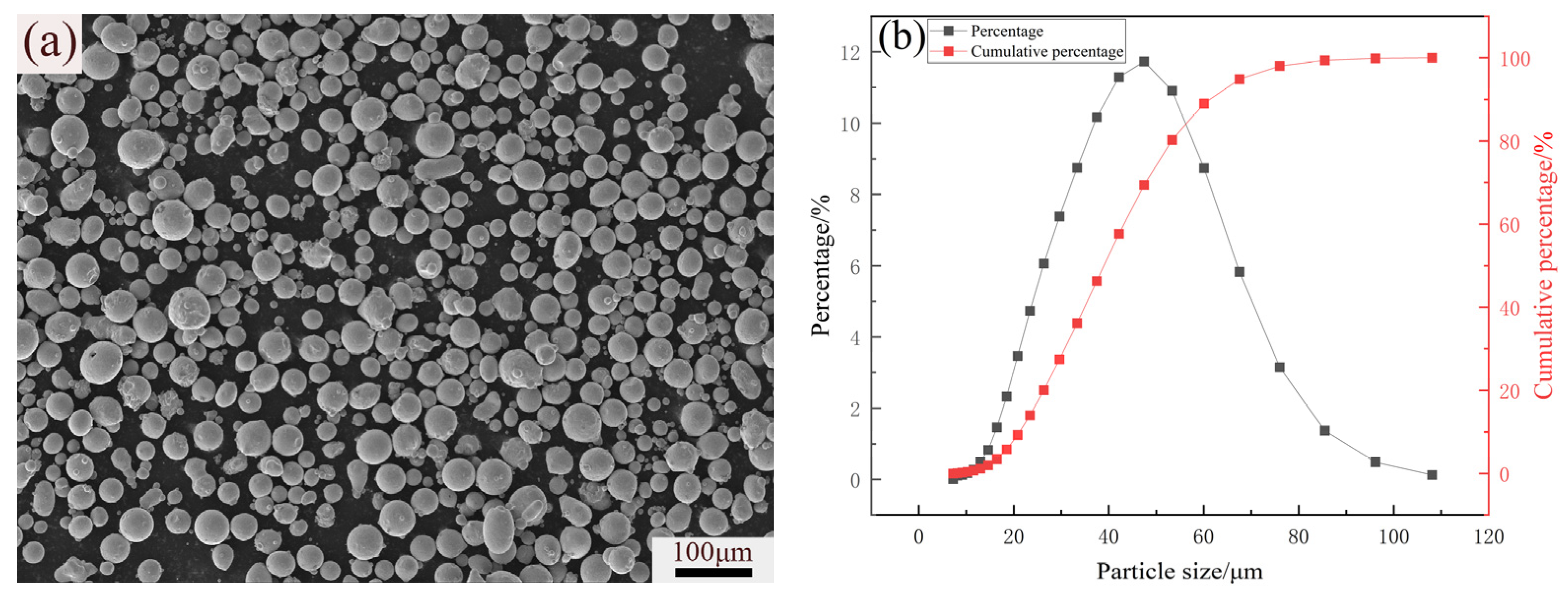
Figure 1 shows the morphology and particle size distribution of gas-atomized 316L powders. The powders were provided by Xi’an Bright Laser Technologies Co., Ltd., and were characterized by a spherical shape and a particle diameter distribution in the range of 8~108 μm. The standard deviation of the spherical powder particle size was ±29 μm. The powders exhibited a normal distribution, indicating good powder flowability, which is conducive to melting and forming. The chemical composition of 316L stainless steel powder and SLM specimens shown in Table 1 was analyzed using inductively coupled plasma (ICP, Plasma 3000, NCS Testing Technology Co., Ltd., Beijing, China) equipment and a carbon and sulfur determinator (CS3500, NCS Testing Technology Co., Ltd., Beijing, China). When using the ICP equipment, Fe, Cr, Ni, Mo, P, Mn, and Si in the SLM specimens were quantified by referencing 316L stainless steel. The results indicated that the elements’ contents were barely changed by the SLM process and heat treatment. These specimens all met the chemical composition requirement for 316L stainless steel in ASTM A666 [32]. To remove the water, the powders and substrate were dried at 120 °C for 2 h before SLM. Because the solution treatment can reduce internal residual stress [25,26] and precipitation of carbides after aging treatment can improve hardness and strength [33], the following three types of heat treatment processes were applied to the SLM 316L specimens in vacuum tubes, as shown in Table 2.
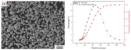
Figure 1.
(a) SEM image and (b) particle size distribution of 316L stainless steel.

Table 1.
Chemical composition of specimens (wt %).
Table 2.
Heat treatment process of specimens.
2.2. Microstructural Characterization
Density is an important parameter for evaluating the quality of additively manufactured specimens. The density of specimens was determined using both the image analysis method with optical microscopy (OM; VHX-X1F, Keyence, Osaka, Japan) and the Archimedes method. The planar density of the specimen was measured using the image analysis method, and the porosity of polished and uncorroded specimens was obtained by calculating the proportion of pores within the image area. The planar density of the specimen (ρm) was obtained via the formula ρm = 1 − ρk, where ρk is the porosity of the specimen. The Archimedes method was used to obtain the Archimedes density of the specimens. First, the mass of the specimens (M1) was measured in air using a balance. Then, a thin layer of Vaseline was applied to the surface of the specimen, and the mass of the specimens in water (M2) was measured. The Archimedes’ density of the specimen (ρt) can be calculated via the following formula [34]:
where ρw is the density of water and ρL is the theoretical density of 316L stainless steel. Every data point was measured 10 times to confirm the accuracy of the density.
The phases of the SLM specimens were analyzed using an X-ray diffractometer (XRD, Rigaku Smart Lab 9 kW, Rigaku Co., Tokyo, Japan) with Cu-Kα radiation in the 2θ range of 35° to 90°. A voltage of 40 kV, a current of 200 mA, and a rotating rate of 2° per minute were employed. Specimens for OM were metallographically prepared to a 1.5 μm diamond polishing and etched by standard aqua regia for 8 s. Grain size was measured in the image using Image-Pro Plus 6.0 software. Microstructural characterization of the specimen was conducted via OM and scanning electron microscopy (SEM, Zeiss Gemini 300, Oberkochen, Germany) equipped with energy dispersive spectroscopy (EDS). The beam energy was 20 keV, and the beam current was 1 nA. Specimens for scanning transmission electron microscopy (STEM) were mechanically ground down to about 50 μm and then electropolished in a solution made with methanol with 10 vol% perchloric at a voltage of 50 V and a temperature of −20 °C. TEM analysis was carried out in a JEOL-2100 TEM at an acceleration voltage of 200 kV.
2.3. Microhardness and Wear Behaviors
Microhardness testing was employed via the indentation method at room temperature. Five indentations were measured using an MHV-1000 Vickers hardness tester with a load of 0.2 kgf and a duration of 15 s. The surface roughness and hardness of the specimen were 17.3 μm and 182.6 HV0.2, respectively. The average microhardness and standard deviation of each specimen were obtained. Dry friction and wear tests were carried out using a ball-on-disk tribometer (HT-1000, Lanzhou Zhongke Kaihua Technology Development Co., Ltd., Lanzhou, China). The test was performed at room temperature, with relative humidity ranging from 40% to 60%. A load of 10 N and a rotation radius of 3 mm were employed. A spherical bearing steel ball (GCr15), 4 mm in diameter, was in contact with the rotating specimen at 1000 rpm for 30 min. Owing to the continuous contact with these types of materials in industrial applications, the counter material (GCr15) was selected. Prior to testing, the specimen was cleaned and dried. The coefficient of friction was obtained using the tangential load over the applied load. The mass change in the specimen before and after the wear test was weighed to calculate the wear mass loss. The wear rate was calculated as the wear mass loss per minute. Each specimen was tested three times, and the average value was calculated. The friction coefficient and wear rate of the specimen were quantitatively analyzed. To further investigate the wear resistance of the specimen, 3D morphologies of the wear track were studied using a VHX-X1F ultra-depth-of-field microscope.
3. Results
3.1. Microstructure Characterization
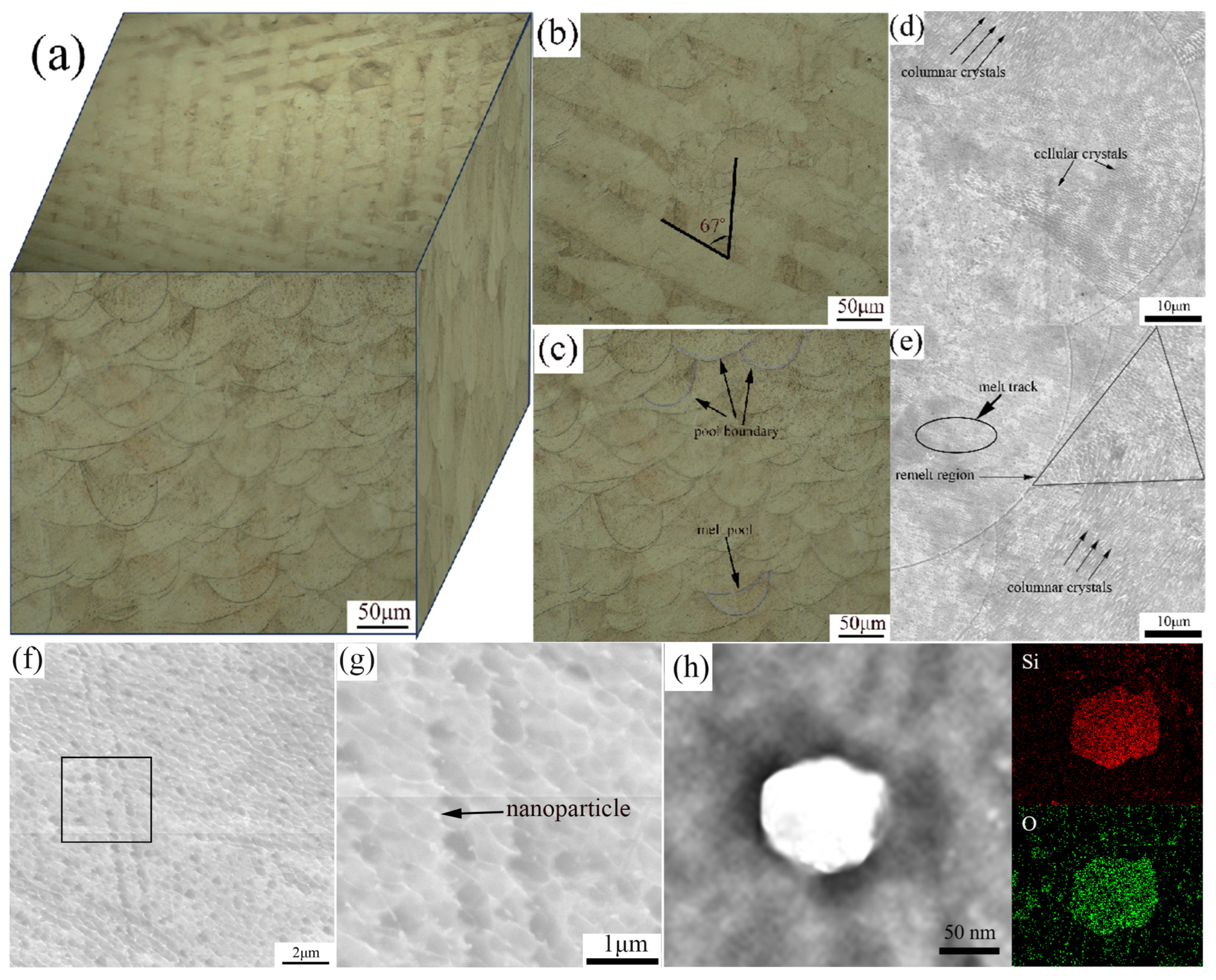
Figure 2 depicts the OM, SEM, and EDS spectrum of the XOY and XOZ planes of specimen a. From the OM images of the XOY and XOZ planes in Figure 2a–c, it can be observed that the specimens exhibit different microstructures in different SLM directions. The microstructure on the XOY plane in Figure 2b shows intersecting melt pools with an intersection angle of approximately 67°, which is consistent with the rotation angle of the laser scanning between layers. The microstructure on the XOZ plane, which is perpendicular to the SLM direction, appears as a fish scale pattern composed of individual micro melt pools, with the curves in Figure 2c representing the boundaries of the melt pools. The microstructure of the SLM specimen exhibits anisotropy in different SLM directions. Figure 2c,d show that the spacing between each SLM layer is about 20 μm, which is consistent with the powder layer thickness. Figure 2d–h display the SEM images of the XOZ plane of specimen a. From Figure 2d, it is evident that the boundaries between adjacent melt pools are clear, and the melt pool is composed of columnar crystals with varying growth directions and cellular crystals of different sizes. The non-uniform energy distribution during the SLM process leads to differences in temperature gradients, resulting in different microstructures within the melt pools. In Figure 2e, the triangular area represents the melt pool overlap region, where cellular crystals grow and coarsen due to the remelting effect of the laser, and the grain size is larger compared to the rapidly solidified cellular crystals in the melt track. The melt pool boundaries in Figure 2e feature columnar crystals that grow directionally due to differences in temperature gradients, and the columnar crystals on the XOZ plane appear as cellular structures on the XOY plane [35]. Figure 2g shows numerous bright nanoparticles attached to the surface of the cellular crystals. To determine which elements segregated at the nanoparticles, STEM-EDS analysis was conducted, as shown in Figure 2h. The analysis revealed that these nanoparticles contain high contents of Si and O, which is consistent with the results reported by previous studies [36,37,38]. The temperature of the molten pool is instantly heated by laser irradiation to above the boiling point (about 2862 °C), causing the initial oxide in the powder to completely dissolve. The rapid cooling of the laser melt pool leads to the enrichment of alloying elements (including Si) at the solid–liquid interface. The Gibbs free energy for the formation of oxides between Si and O is much lower than that of the other components [39]. Nano-oxide particles can attach to grain boundaries and play a role in precipitate strengthening [35].
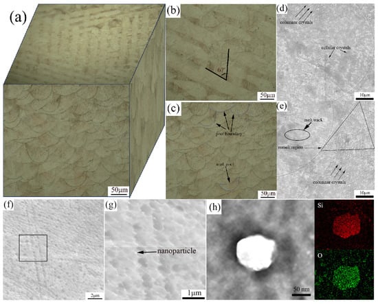
Figure 2.
Microstructure characterization of SLM 316L. (a) OM of three-dimensional microstructure, (b) OM of XOY plane, (c) OM of XOZ plane, (d) SEM characteristic of melting pools, (e) columnar crystals, cellular crystals, and remelted zone, (f) cellular crystals, (g) higher magnification of cellular crystals, (h) STEM-EDS elemental mapping of nanoparticles.
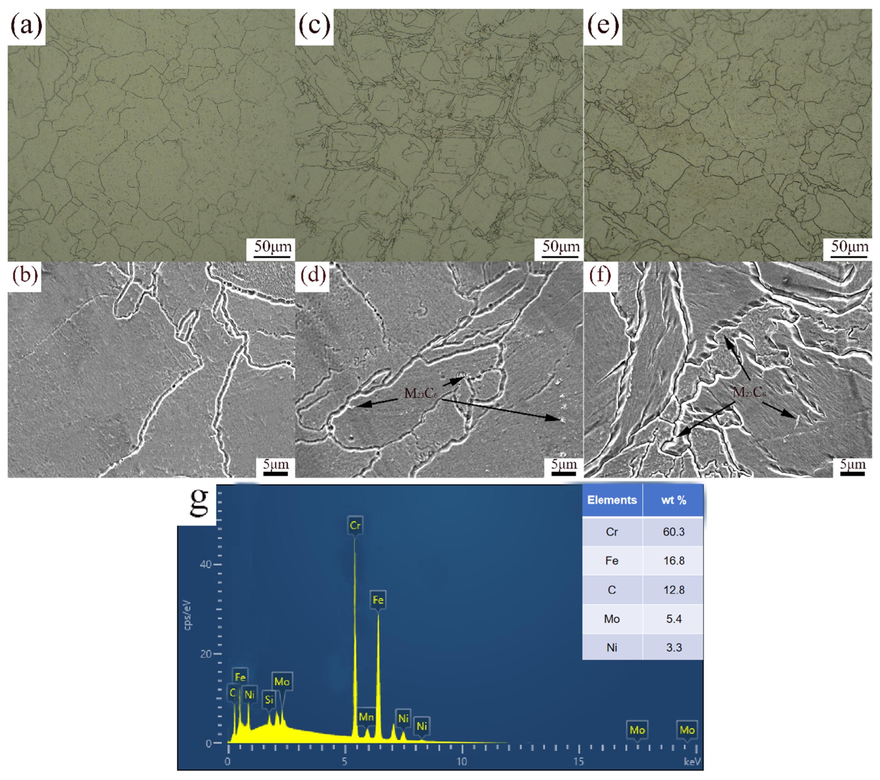
The OM and SEM images of the microstructure of specimens b, c, and d are shown in Figure 3. After solution treatment at 1050 °C for 2 h, the grain size of specimen b increased, as shown in Figure 3a. The grain size was large and uniform, and grain boundaries were clear. Recrystallization was completed during heating to 1050 °C, followed by significant grain growth during solution treatment. The cellular structure within the melt pool coarsened, transforming into irregular grains. The solution treatment temperature is higher than the recrystallization temperature of 316L stainless steel (900 °C) [9], which promotes the recrystallization and growth of grains. At high temperatures, alloying elements (such as Cr, Ni, and Mo) were fully dissolved into the austenite matrix, eliminating segregation that may occur during SLM processes, releasing residual stresses, and achieving a more uniform microstructure. After aging at 850 °C for 2 h, grain boundary migration occurred, and melt pool boundaries were altered as a result of grain growth, as shown in Figure 3c. Due to limited recrystallization, some of the grain growth presented as blocky grains of varying shapes, and a large number of small recrystallized grains appeared. A small amount of particle phase at grain boundaries and within the grains can be observed in Figure 3d. According to the EDS analysis in Figure 3g, the C content of the particle phase is significantly higher (43.54%), and the Cr content is higher (12.98%), indicating that the particle phase exists in the form of carbides, that is, carbides (M23C6) precipitate at the grain boundaries [40]. The precipitation temperature for carbides and intermetallic compounds in 316L stainless steel is 850 °C, and aging treatment promotes the precipitation of alloying elements (such as Cr and Mo) from supersaturated solid solutions. After solution treatment at 1050 °C for 2 h and aging treatment at 850 °C for 2 h, further recrystallization occurred, and the grains coarsened further. The grain size of specimen d, shown in Figure 3e, increased to 43.5 μm. When subjected to solution treatment, after reaching the austenitization temperature, the elements at the boundary of the melt pool further dissolved and diffused. The melt pool boundaries and fish scale melt pools disappeared, leading to grain growth and coarsening. When subjected to aging treatment, the recrystallized grains became larger. Compared to specimens with aging treatment, the grain size was larger and more uniform. In Figure 3f, the distribution of precipitated phases is more uniform, and the size is smaller. Solid solution treatment eliminates the non-equilibrium structure during the SLM process, resulting in a uniform distribution of alloy elements and providing a uniform matrix for subsequent aging treatment. Grain growth and coarsening with recrystallization are inevitably affected by the heating temperature, holding time, and cooling rate, among other factors. Kong [41] reported a slight increase in the grain size of SLM 316L subjected to heat treatment (at lower temperatures and shorter holding times). Due to the complete recrystallization, the grain size exhibited significant growth when subjected to higher temperatures and longer holding times.
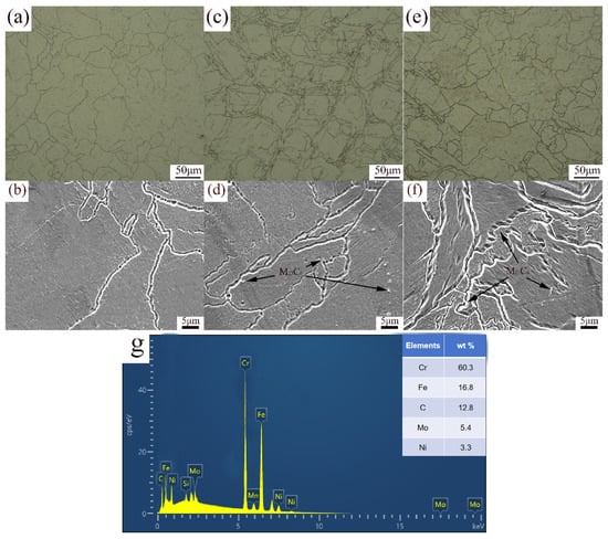
Figure 3.
OM and SEM images of XOZ surface: (a,b) specimen b, (c,d) specimen c, (e,f) specimen d, (g) EDS spectra of M23C6.
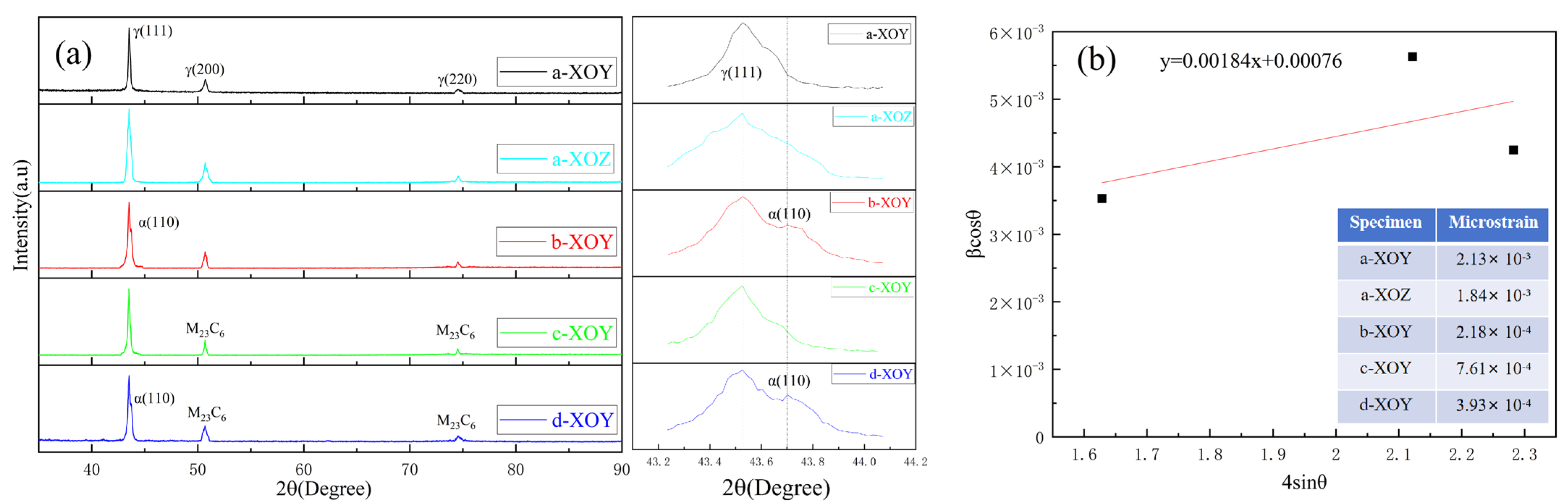
Figure 4 shows the XRD pattern of specimens a–d. The XRD analysis results of specimen a in Figure 4 reveal that only one phase exists: a γ face-centered cubic (fcc) austenite phase. The XRD results indicate that the 316L stainless steel prepared by SLM exhibits anisotropy in the grain orientation of the XOY and XOZ planes. Yang et al. [31] fabricated SLM 316L and reported a weak textural degree and low alignment with the <001>, <101>, and <111> directions on the front surface (corresponding to the XOZ plane), along with strong <100> texture growth orientation of grains on the top surface (corresponding to the XOY plane). After solution treatment, the XRD pattern of the XOY planes of SLM specimen b was found to be uniform, featuring two main phases: the γ face-centered cubic (fcc) austenite phase and the α body-centered cubic (bcc) ferrite phase [42]. In the right magnified portion of Figure 4a, the XRD results indicate that secondary peaks corresponding to the α ferrite phase can be observed in solution-treated and solution + aging-treated specimens, in addition to a dominant γ austenite phase. The γ austenite phase is generated when a high-energy laser is irradiated on the surface of the powder. When heat-treated, the γ austenite phase will transform into the α ferrite phase during the cooling process [43]. The phase transition is affected by the temperature, holding time, and cooling rate, and a small portion of the α ferrite phase is retained due to the significant differences in cooling rates. Besides γ austenite phases, specimens c and d exhibited M23C6 carbide phases.
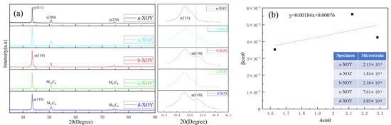
Figure 4.
(a) XRD patterns of specimens, (b) Williamson–Hall plot of specimen and microstrains.
The Williamson–Hall (W–H) method is commonly used to calculate microstrain (), and the following is the formula based on the Williamson–Hall method [22]:
where β is the full width at half maximum (FWHM) of the diffraction peak, θ is the Bragg angle of the diffraction peak, k is the Scherrer constant (0.94), λ is the wavelength of the X-ray (0.15406), and D is the grain size. The Williamson–Hall plot and microstrain of the XOY and XOZ plane of specimen a, XOY plane of specimen b, XOY plane of specimen c, and XOY plane of specimen d are shown in Figure 4b. After solution treatment, the microstrain of SLM 316L stainless steel was significantly reduced. At high temperatures, the grains undergo recrystallization and growth, and the solution elements are fully dissolved into the matrix. The microstrain and solute segregation generated during the rapid cooling process were eliminated, and the stress concentration at the grain boundaries was reduced. After aging treatment, the microstrain of SLM 316L stainless steel increased compared to that of the solution-treated SLM 316L stainless steel, but it remained lower than that of SLM 316L stainless steel. This is because the precipitation of M23C6 carbides at grain boundaries may lead to localized stress concentration, thereby increasing the microstrain. After solution + aging treatment, the microstrain of SLM 316L stainless steel lies between that of the solution-treated and aging-treated states. The solution treatment first eliminates melt pool boundaries and microstrain, homogenizes the grains, and induces recrystallization. The subsequent aging treatment promotes the precipitation of carbides at grain boundaries. While these precipitates can enhance microhardness, they may also lead to an increase in microstrain.
3.2. Density
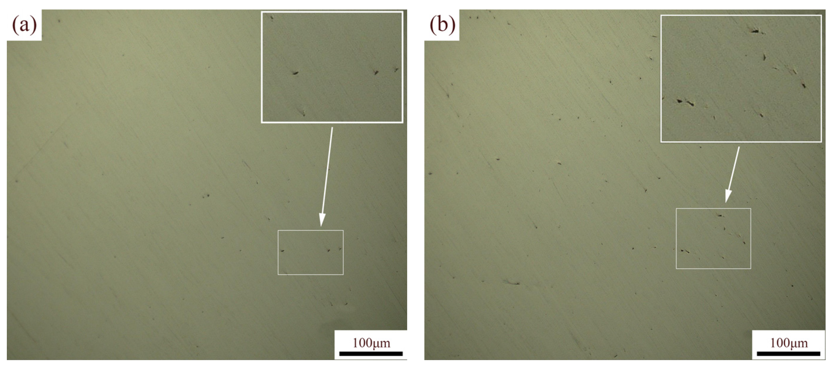
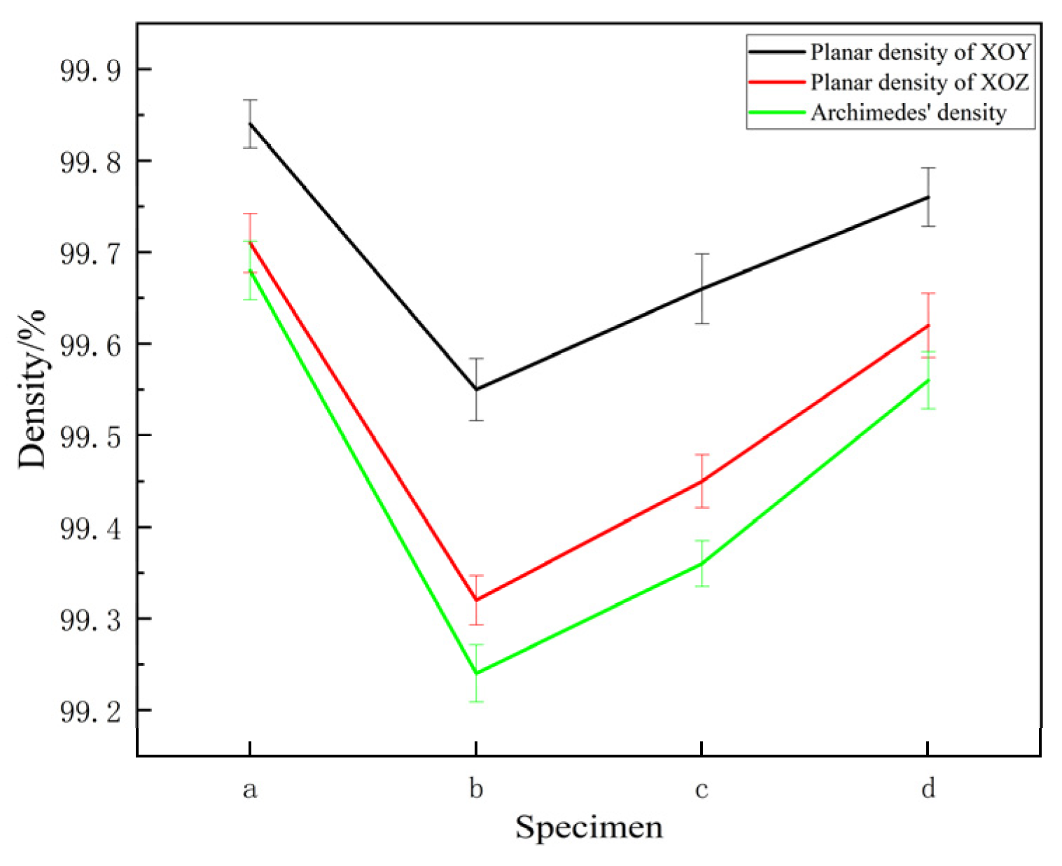
Figure 5a,b show the OM of the XOY and XOZ planes, with the planar density of the specimen calculated based on the pores visible in the images. As shown in Figure 6, the planar densities of the XOY and XOZ planes of the specimen are slightly higher than the Archimedes densities. This may be due to the sampling position of the planar density and the difficulty in resolving fine pores using a microscope. In addition, the planar density of the XOY plane was slightly higher than that of the XOZ plane. The Archimedes densities of specimens a–d measured via the Archimedes method were above 99%, indicating that the SLM 316L stainless steel specimens were dense [44]. After heat treatment, the Archimedes densities of the specimens slightly decreased, and the Archimedes density of the specimens subjected to solution + aging treatment was the highest. Although the density variation is minimal, it demonstrates a statistically significant increasing trend. During the heat treatment process, a phase transition occurred, as shown in Figure 2, with the densities of different phase states varying. The density of the austenite phase in stainless steel is usually higher than that of the ferrite phase. Specifically, the density of austenitic stainless steel is generally between 7.93 and 8.00 g/cm3, and the density of ferritic stainless steel is generally between 7.70 and 7.85 g/cm3. The volume change accompanying the phase transition process may cause local deformation or microcracks, thereby reducing the density. Secondly, with heat treatments, the grains recrystallized, and the grain coarsened. Grain coarsening may damage the high-density interlayer bonding of SLM 316L, leading to the formation of defects such as micropores or cracks at grain boundaries, thereby reducing the density. In addition, the interfacial bonding strength of coarse grains may be weaker than that of fine grains, further exacerbating the decrease in density. Solution treatment can improve the microstructure uniformity of materials, but at the same time, it may lead to an increase in porosity inside the material, thereby reducing its density. Aging treatment promotes the precipitation of carbides, which can hinder further grain growth and increase density. However, SLM 316L is close to full density, and the difference in density between the precipitated phase M23C6 and the matrix is small, so the overall difference is limited.
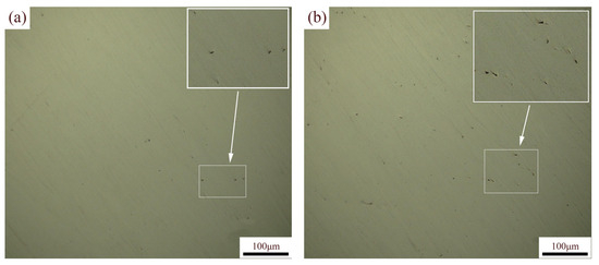
Figure 5.
OM of SLM 316L on different planes: (a) XOY plane, (b) XOZ plane.
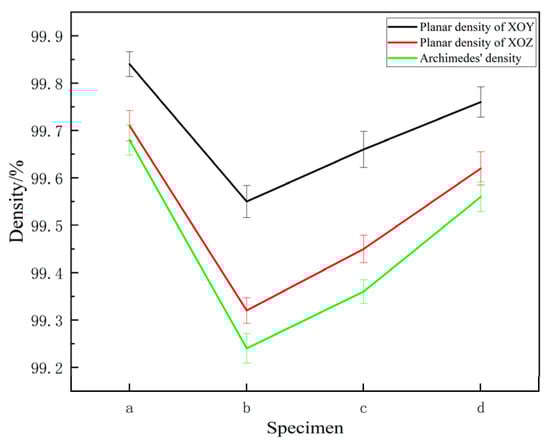
Figure 6.
Planar and Archimedes densities of specimens a–d.
3.3. Microhardness
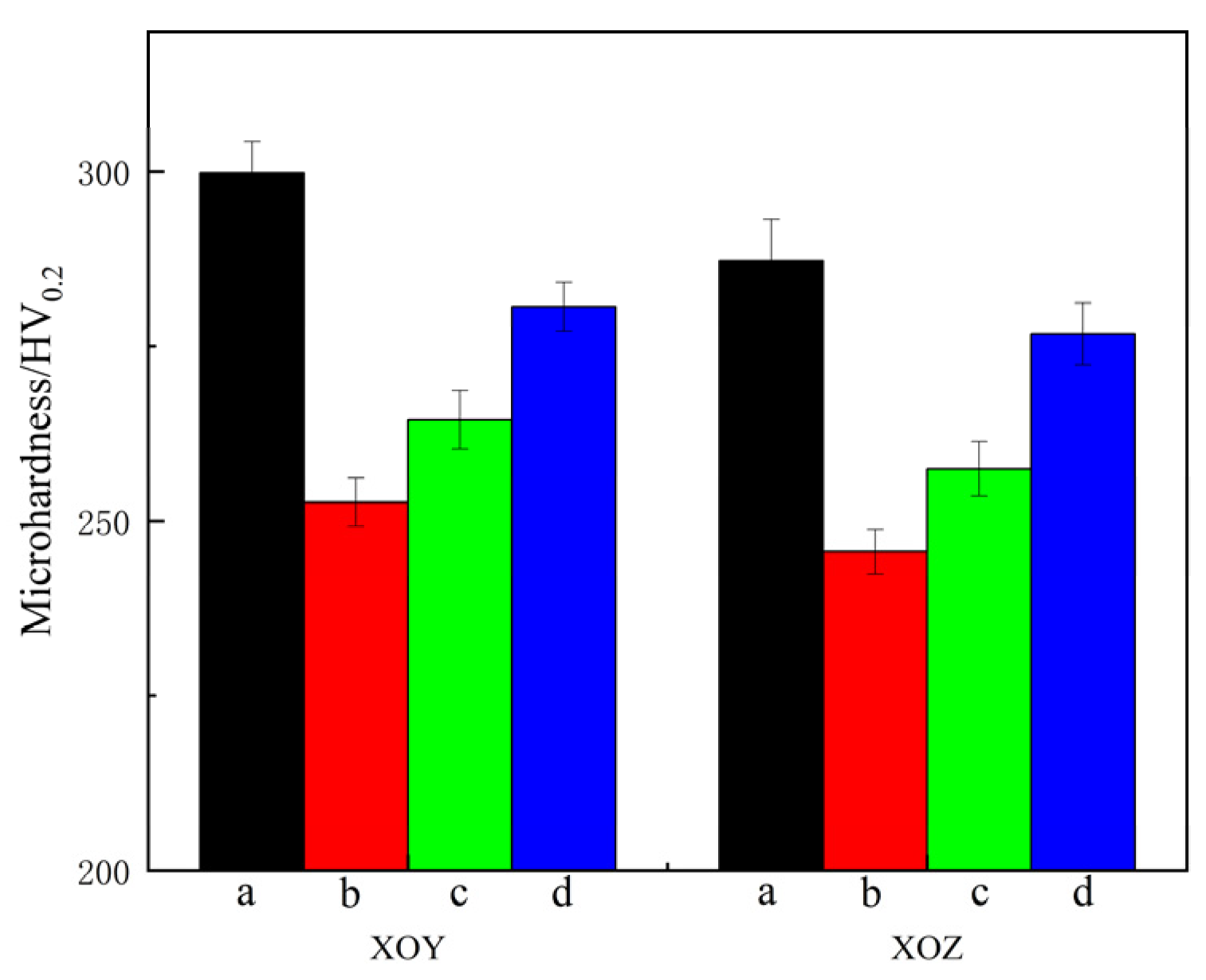
Figure 7 shows the microhardness of the XOY and XOZ planes of specimens a–d. The error bars in Figure 7 correspond to the standard deviations of microhardness. The microhardness values of the XOY and XOZ planes of specimen a are 298.5 HV0.2 and 291.3 HV0.2, respectively. Comparative analysis of the microhardness of specimens a–d on the XOY and XOZ planes reveals that the microhardness of the XOY plane is equivalent to, or slightly higher than, that of the XOZ plane. The difference in microhardness between the XOY plane and the XOZ plane of sample a is more obvious. This is mainly related to the anisotropy in the microstructure of specimen a on the XOY and XOZ planes. The microhardness values are affected by grain size and porosity. Due to the higher number of cellular crystals on the XOY plane, smaller grain size, and higher density, the microhardness of the XOY plane is higher. After heat treatment, the microhardness of specimens b–d on both the XOY and XOZ planes slightly decreases compared to specimen a, and the decrease in specimen d is the lowest. After heat treatment, the microhardness decreases, which is related to grain coarsening and the disappearance of melt pool boundaries. According to the Hall–Petch formula [45], the finer the grains in dense metal materials, the greater the resistance to dislocation slip along grain boundaries and the higher the microhardness. The Si-O nano-oxide particles, as non-deformable phases, significantly improve the microhardness of SLM 316L by hindering dislocation movement through dispersion strengthening. The formation of the precipitated phase (M23C6) will pin dislocations and grain boundaries, leading to an increase in microhardness. Aging treatment enhances the microhardness via precipitation strengthening. Additionally, the density decreases after heat treatment, leading to a decrease in microhardness for specimens b–d.

Figure 7.
Microhardness of specimens a–d.
3.4. Friction and Wear
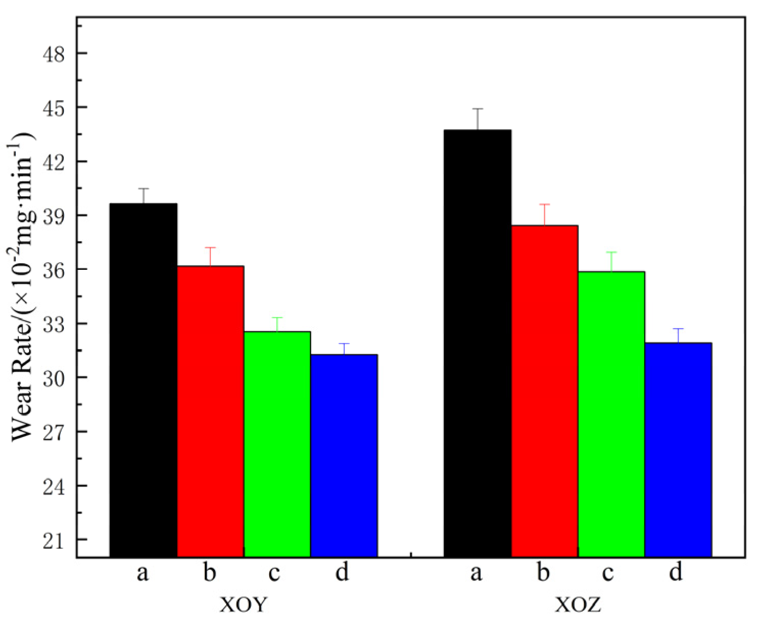
The variation in the friction coefficients of specimens a–d on the XOY and XOZ planes under a 10 N load at 1000 r/min for 30 min at room temperature is shown in Figure 8, and the wear rate is shown in Figure 9. The error bars in Figure 7 correspond to the standard deviations of wear rate in Figure 9, ranging from 0.006 to 0.01667. In the initial stage of friction, the friction coefficient rises sharply due to the cold welding effect between the grinding ball and the friction surface. As cold welding points and wear and tear debris are generated and expelled, the friction coefficient stabilizes. A comparative analysis of the XOY and XOZ planes of each specimen in Figure 8a,b reveals that the friction coefficient of the XOY plane is slightly lower than that of the XOZ plane, indicating that the XOY plane has better anti-friction performance than the XOZ plane. The friction coefficients of specimens b–d are reduced, indicating better anti-friction properties after heat treatment. Figure 9 shows that the wear rate of the XOY plane is less than that of the XOZ plane for specimen a, indicating the wear anisotropy of specimen a. The wear rates of the XOY and XOZ planes are 0.3963 mg/min and 0.4373 mg/min, respectively. After heat treatment, the wear rate of the XOY plane and XOZ plane of the specimen decreases, and the wear resistance is improved compared to SLM 316L. The difference in the wear rate between the XOY and XOZ surfaces decreases, and the wear anisotropy of the heat-treated specimen weakens. When subjected to solution + aging treatment, the wear rates of the XOY plane and XOZ plane decreased to 0.3127 mg/min and 0.319 mg/min, respectively, which are 21.1% and 27.1% lower than that of SLM 316L; the wear resistance of specimen d is the best.
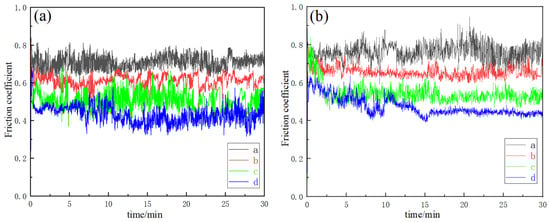
Figure 8.
Friction coefficient of specimens a–d. (a) XOY, (b) YOZ.

Figure 9.
Wear rate of specimens a–d.
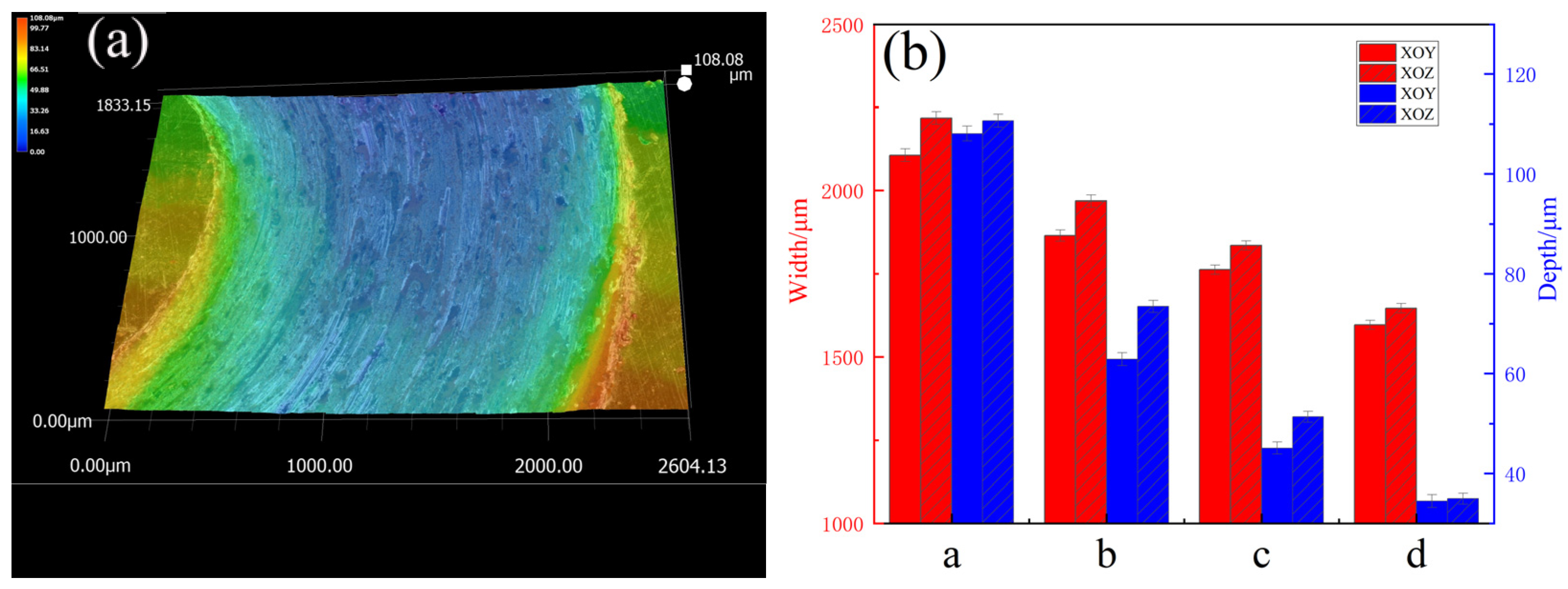
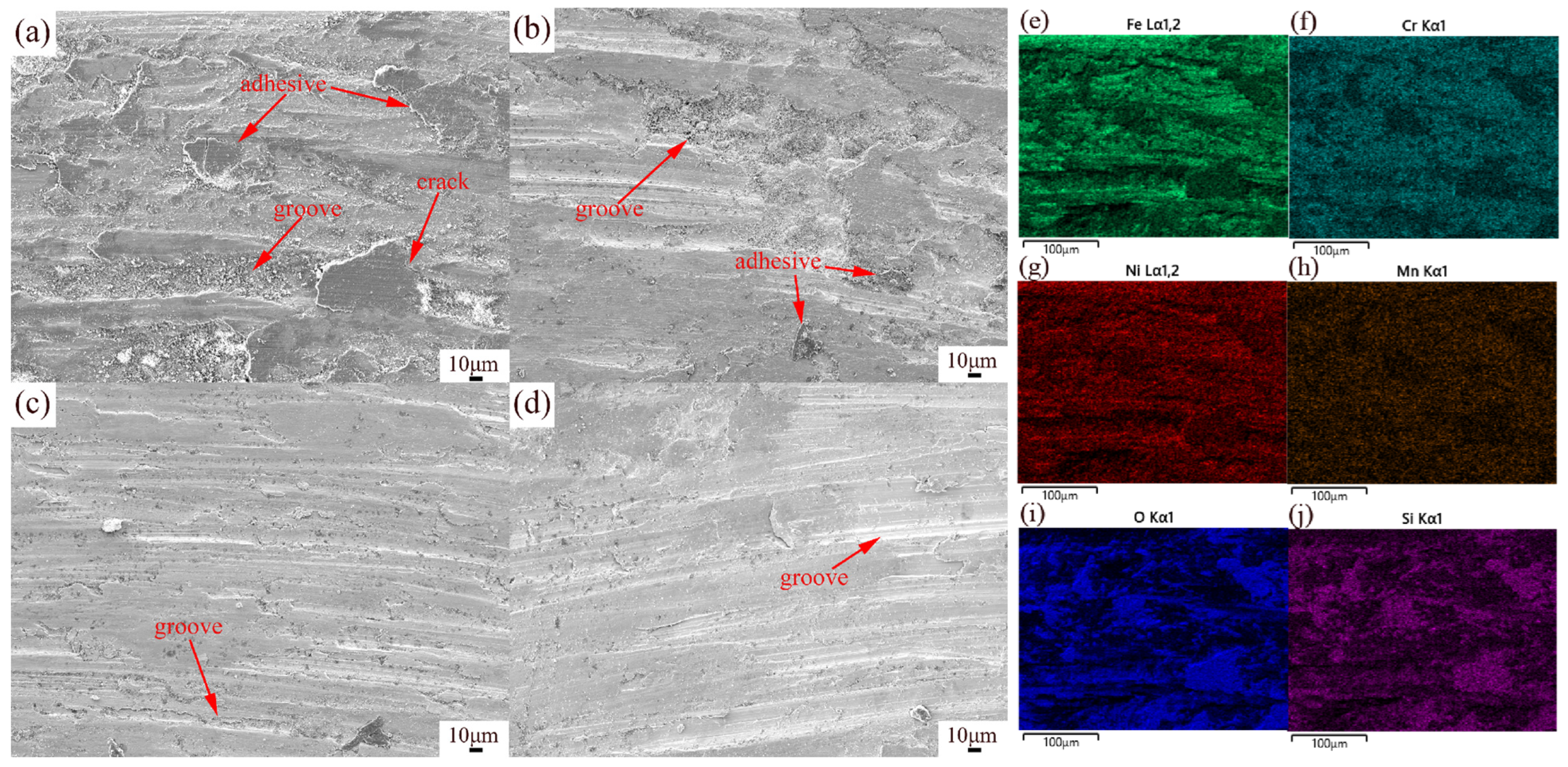
To further analyze the wear characteristics of the specimens, a super-depth-of-field microscope was used to characterize the 3D morphologies of the wear track, as shown in Figure 10a. The width and depth of wear tracks on the XOY and XOZ planes were quantitatively analyzed. The results revealed that the former’s wear tracks were shallower and narrower than the latter’s, further proving that the wear resistance of the XOY plane is better than that of the XOZ plane. After heat treatment, the wear track depth became shallower and the width became narrower, indicating better wear resistance. This evidence from the other side shows that the wear resistance of the specimen with solution + aging treatment was the best. This may be due to grain coarsening caused by heat treatment. Figure 11 shows the SEM morphologies and EDS elemental maps of the wear surfaces of the XOZ plane. As seen in Figure 11, the wear surface exhibits adhesive and abrasive wear. As shown in Figure 11a, there are deep plowing grooves, cracks, large debris, and adhesives on the wear surface of the SLM 316L specimen. In Figure 11b, the plowing grooves are shallower, and there is less adhesive on the wear surface of the specimen subjected to solution treatment. When subjected to aging treatment, the plowing grooves are shallower and narrower, as shown in Figure 11c. The plowing grooves of specimen d (subjected to solution + aging treatment) are narrowest and shallowest, as shown in Figure 11d. The EDS results of SLM 316L in Figure 11e–j show the presence of Fe, Cr, Ni, Mn, Si, and O in Figure 11a. Si and O agglomerate on the adhesive surface, and the oxygen content is higher than that in Figure 11i, which may be caused by abrasive oxidation. In addition, Si-O nano-oxide particles became coarsened after heat treatment [38], dispersing within the specimens, playing a role in precipitation and dispersion strengthening and thus enhancing the resistance to shear and furrowing [46].

Figure 10.
(a) Three-dimensional morphology of wear track, (b) quantitative analysis of wear track width and depth.

Figure 11.
SEM images of wear surfaces: (a) specimen a, (b) specimen b, (c) specimen c, (d) specimen d. (e–j) EDS element composition analysis of specimen a.
Generally, the higher the microhardness of a material, the better its ability to resist plastic deformation and the better its wear resistance [47]. However, SLM 316 stainless steel without heat treatment has a higher microhardness but poorer wear resistance, which may be due to its higher microstrain [48] and greater brittleness [49], making it more prone to crack formation and surface spalling under repeated friction loads. When a constant load is applied to SLM 316L, microcracks are prone to occur at stress concentration points, such as grain boundaries and defects. These microcracks propagate and connect during the wear process, forming a larger crack network and ultimately leading to peeling off the large pieces of debris. After heat treatment, the microstrain of the specimen decreased, and the resistance to plastic deformation was better. When applying solution + aging treatment, the density of specimen d was higher than that of specimens b and c, indicating fewer pores in specimen d. The presence of pores can disrupt the continuity of materials and cause stress concentration [50]. Under dry friction conditions, fewer pores led to lower friction coefficients and less wear loss, which represented better wear resistance for specimen d. Si-O nano-oxide particles can reduce crack propagation during the wear process and improve the interfacial bonding strength of materials to reduce the size of wear debris [51].
When applying solution treatment, a uniform austenite microstructure mitigates localized stress concentration and inhibits crack propagation, while the associated reduction in microhardness may enhance susceptibility to abrasive wear. Thus, specimen b exhibits severe abrasive wear and adhesive wear mechanisms. When applying aging treatment, it promotes the precipitation of M23C6 carbides at grain boundaries and within grains. The M23C6 carbides themselves act as hard phases and improve the microhardness, resist abrasive wear during friction, and reduce material loss. During sliding contact, M23C6 carbides act as load-bearing phases, effectively hindering the movement of dislocations and thereby reducing severe plastic deformation of the matrix. As a result, specimen c exhibits an abrasive wear mechanism. When applying solution + aging treatment, the uniform austenite matrix inhibits crack propagation, and the dispersed M23C6 carbides reduce severe plastic deformation; specimen d exhibits an abrasive wear mechanism.
Hence, although the density and microhardness of SLM 316L are the highest among the four types of specimens, the wear resistance of the specimen subjected to solution treatment + aging treatment is the best.
4. Conclusions
In this study, the effect of different heat treatments on the microstructure anisotropy, density, microhardness, and wear resistance of an SLM 316L specimen was investigated.
- XRD analysis of SLM 316L demonstrated a γ austenite phase, and specimens subjected to solution + aging treatment exhibited M23C6 carbides and γ austenite and α ferrite phases. Furthermore, the microstrain was reduced with heat treatment.
- The microstructure of the SLM 316L specimen exhibited intersecting melt pools on the XOY plane and fish scale-like melt pools on the XOZ plane. The melt pools were composed of columnar crystals and cellular crystals due to the rapid solidification characteristic. The anisotropy of microstructures on the XOY and XOZ planes resulted in differences in density and microhardness. Following heat treatment, the melt pool boundaries were eliminated, carbides (M23C6) precipitated at grain boundaries and within the grains, and the microstructures coarsened but became more uniform.
- The finer microstructure of SLM 316L resulted in higher density and microhardness. Compared with SLM 316L, the microhardness decreased after heat treatment, and the density and microhardness of the specimens subjected to solution + aging treatment were the highest among heat-treated specimens.
- The wear resistance of the XOY plane in specimen a is superior to that of the XOZ plane. The specimen subjected to solution + aging treatment exhibited the lowest friction coefficient and wear rate, with the wear track found to be the narrowest and shallowest. The wear rates of specimens of the XOY and XOZ planes after solution + aging treatment were 21.1% and 27.1% lower than that of SLM 316L. The specimen subjected to solution + aging treatment exhibited the best wear resistance due to the lower microstrain and higher microhardness.
Author Contributions
Conceptualization, M.S., Q.Z., J.W., H.W., X.W., H.Z., Y.A., Y.L. and L.M.; Methodology, M.S., Q.Z., J.W., H.W., X.W., H.Z., Y.A., Y.L. and L.M.; Validation, M.S.; Data curation, M.S.; Writing—original draft, M.S.; Writing—review and editing, M.S. and J.W. All authors have read and agreed to the published version of the manuscript.
Funding
This project was supported by the National Natural Science Foundation of China (Grant No. 51965053) and the Research Business Expenses in Inner Mongolia Autonomous Region First-Class Discipline Research Special Project (YLXKZX-NKD-042).
Data Availability Statement
The original contributions presented in the study are included in the article. Further inquiries can be directed to the corresponding author.
Conflicts of Interest
The authors declare no conflicts of interest.
References
- Dadkhah, M.; Mosallanejad, M.H.; Iuliano, L.; Saboori, A. A Comprehensive Overview on the Latest Progress in the Additive Manufacturing of Metal Matrix Composites: Potential, Challenges, and Feasible Solutions. Acta Metall. Sin. 2021, 34, 1173–1200. [Google Scholar] [CrossRef]
- Mazyar, A.; Mobin, K.; Ehsan, T. Adaptive Model-based Optimization for Fusion-based Metal Additive Manufacturing (directed energy deposition). J. Manuf. Process. 2023, 108, 588–595. [Google Scholar]
- Song, W.; Yang, J.; Liang, J.; Lu, N.; Zhou, Y.; Sun, X.; Li, J. A New Approach to Design Advanced Superalloys for Additive Manufacturing. Addit. Manuf. 2024, 84, 104098. [Google Scholar] [CrossRef]
- Timothy, M.S.; Christopher, A.K.; Nikolai, A.Z.; Bryan, J.H.; Milan, H.; Paul, R.G.; Aaron, C.T.; Michael, J.M.; Timothy, P.G.; John, W.L. A 3D Printable Alloy Designed for Extreme Environments. Nature 2023, 617, 513–518. [Google Scholar]
- Ataee, A.; Li, Y.; Wen, C. A Comparative Study on the Nanoindentation Behavior, Wear Resistance and in Vitro Biocompatibility of SLM Manufactured CP–Ti and EBM Manufactured Ti64 Gyroid Scaffolds. Acta Biomater. 2019, 97, 587–596. [Google Scholar] [CrossRef] [PubMed]
- Ngo, T.D.; Kashani, A.; Imbalzano, G.; Nguyen, K.T.Q.; Hui, D. Additive Manufacturing (3D printing): A Review of Materials, Methods, Applications and Challenges. Compos. Part B Eng. 2018, 14, 172–196. [Google Scholar] [CrossRef]
- Andac, O.; Eda, A.; Arcan, F.D. Selective Laser Melting of Nano-TiN Reinforced 17-4 PH Stainless Steel: Densification, Microstructure and Mechanical Properties. Mater. Sci. Eng. A 2021, 836, 142574. [Google Scholar]
- Ji, P.C.; Wang, Z.H.; Mu, Y.K.; Jia, Y.D.; Wang, G. Microstructural Evolution of (FeCoNi)85.84Al7.07Ti7.09 High-entropy Alloy Fabricated by an Optimized Selective Laser Melting Process. Mater. Des. 2022, 224, 111326. [Google Scholar] [CrossRef]
- Saeidi, K.; Gao, X.; Lofaj, F.; Kvetková, L.; Shen, Z. Transformation of Austenite to Duplex Austenite-Ferrite Assembly in Annealed Stainless Steel 316L Consolidated by Laser Melting. J. Alloys Compd. 2015, 633, 463–469. [Google Scholar] [CrossRef]
- Abdali, A.; Nedjad, S.H.; Zargari, H.H.; Saboori, A.; Yildiz, M. Predictive Tools for the Cooling Rate-dependent Microstructure Evolution of AISI 316L Stainless Steel in Additive Manufacturing. J. Mater. Res. Technol. 2024, 29, 5530–5538. [Google Scholar] [CrossRef]
- Jabarzadeh, S.; Ghalebahman, G.A.; Najibi, A. Investigation into Microstructure, Mechanical Properties, and Compressive Failure of Functionally Graded Porous Cylinders Fabricated by SLM. Eng. Fail. Anal. 2024, 165, 108794. [Google Scholar] [CrossRef]
- Das, A.; Yadav, V.; AlMangour, B.; Prasad, H.C.; Sathish, N.; Ashiq, M.; Srivastava, A.K. Additive Manufacturing of Graphene Reinforced 316L Stainless Steel Composites with Tailored Microstructure and Mechanical Properties. Mater. Chem. Phys. 2023, 303, 127826. [Google Scholar] [CrossRef]
- Kumar, P.; Jayaraj, R.; Suryawanshi, J.; Satwik, U.; McKinnell, J.; Ramamurty, U. Fatigue Strength of Additively Manufactured 316L Austenitic Stainless Steel. Acta Mater. 2020, 199, 225–239. [Google Scholar] [CrossRef]
- Bakhtiarian, M.; Omidvar, H.; Mashhuriazar, A.; Sajuri, Z.; Gur, C.H. The Effects of SLM Process Parameters on the Relative Density and Hardness of Austenitic Stainless Steel 316L. J. Mater. Res. Technol. 2024, 29, 1616–1629. [Google Scholar] [CrossRef]
- Li, H.; Ramezani, M.; Li, M.; Ma, C.; Wang, J. Effect of Process Parameters on Tribological Performance of 316L Stainless Steel Parts Fabricated by Selective Laser Melting. Manuf. Lett. 2018, 16, 36–39. [Google Scholar] [CrossRef]
- Zhu, Y.; Zou, J.; Chen, X.; Yang, H. Tribology of Selective Laser Melting Processed Parts: Stainless Steel 316L under Lubricated Conditions. Wear 2016, 350–351, 46–55. [Google Scholar] [CrossRef]
- Li, H.; Ramezani, M.; Li, M.; Ma, C.; Wang, J. Tribological performance of selective laser melted 316L stainless steel. Tribol. Int. 2018, 128, 121–129. [Google Scholar] [CrossRef]
- Sun, Y.; Moroz, A.; Alrbaey, K. Sliding Wear Characteristics and Corrosion Behaviour of Selective Laser Melted 316L Stainless Steel. J. Mater. Eng. Perform. 2014, 23, 518–526. [Google Scholar] [CrossRef]
- Smith, W.L.; Roehling, J.D.; Strantza, M.; Ganeriwala, R.K.; Ashby, A.S.; Vrancken, B.; Clausen, B.; Guss, G.M.; Brown, D.W.; McKeown, J.T.; et al. Residual Stress Analysis of in Situ Surface Layer Heating Effects on Laser Powder Bed Ffusion of 316L Stainless Steel. Addit. Manuf. 2021, 37, 102252. [Google Scholar]
- Chepkoech, M.; Owolabi, G.; Warner, G. Investigation of Microstructures and Tensile Properties of 316L Stainless Steel Fabricated via Laser Powder Bed Fusion. Materials 2024, 17, 913. [Google Scholar] [CrossRef]
- Herzog, D.; Seyda, V.; Wycisk, E.; Emmelmann, C. Additive Manufacturing of Metals. Acta Mater. 2016, 117, 371–392. [Google Scholar] [CrossRef]
- Maleki, E.; Unal, O.; Doubrava, M.; Pantelejev, L.; Bagherifard, S.; Guagliano, M. Application of Impact-based and Laser-based Surface Severe Plastic Deformation Methods on Additively Manufactured 316L: Microstructure, Tensile and Fatigue Behaviors. Mater. Sci. Eng. A 2024, 916, 147360. [Google Scholar] [CrossRef]
- Chao, Q.; Thomas, S.; Birbilis, N.; Cizek, P.; Hodgson, P.D.; Fabijanic, D. The Effect of Post-processing Heat Treatment on the Microstructure, Residual Stress and Mechanical Properties of Selective Laser Melted 316L Stainless Steel. Mater. Sci. Eng. A 2021, 821, 1441611. [Google Scholar] [CrossRef]
- Peng, P.; Wang, K.S.; Wang, W.; Han, P.; Zhang, T.; Liu, Q.; Zhang, S.; Wang, H.; Qiao, K.; Liu, J. Relationship between Microstructure and Mechanical Properties of Friction Stir Processed AISI 316L Steel Produced by Selective Laser Melting. Mater. Charact. 2020, 163, 110283. [Google Scholar] [CrossRef]
- Zhang, S.; Jia, M.; Wang, W.; Hou, J.; Kuang, W. The Effects of Heat Treatment and Surface State on the Corrosion Resistance of Laser Powder Bed Fusion 304L Stainless Steel in 3.5 wt% NaCl Solution. J. Mater. Res. Technol. 2024, 29, 5620–5632. [Google Scholar] [CrossRef]
- Kong, D.; Dong, C.; Ni, X.; Zhang, L.; Yao, J.; Man, C.; Cheng, X.; Xiao, K.; Li, X. Mechanical Properties and Corrosion Behavior of Selective Laser Melted 316L Stainless Steel after Different Heat Treatment Processes. J. Mater. Sci. Technol. 2019, 35, 1499–1507. [Google Scholar] [CrossRef]
- Patrik, P.; Tibor, K.; Jana, B.; Bidulský, R.; Grande, M.A.; Manfredi, D.; Weiss, K.-P.; Kočiško, R.; Lupták, M.; Pokornýal, I. Investigation of the Properties of 316L Stainless Steel after AM and Heat Treatment. Materials 2023, 16, 3935. [Google Scholar] [CrossRef] [PubMed]
- Yin, H.S.; Song, M.; Deng, P.; Li, L.; Prorok, B.C.; Lou, X. Thermal Stability and Microstructural Evolution of Additively Manufactured 316L Stainless Steel by Laser Powder Bed Fusion at 500–800 °C. Addit. Manuf. 2021, 41, 101981. [Google Scholar] [CrossRef]
- Shankar, P.; Shaikh, H.; Sivakumar, S.; Venugopal, S.; Sundararaman, D.; Khatak, H. Effect of Thermal Aging on the Room Temperature Tensile Properties of AISI Type 316LN Stainless Steel. J. Nucl. Mater. 1999, 264, 29–34. [Google Scholar] [CrossRef]
- Zhou, B.G.; Xu, P.W.; Li, W.; Liang, Y.L.; Liang, Y. Microstructure and Anisotropy of the Mechanical Properties of 316L Stainless Steel Fabricated by Selective Laser Melting. Metals 2021, 11, 775. [Google Scholar] [CrossRef]
- Yang, Y.; Zhu, Y.; Khonsari, M.; Yang, H. Wear Anisotropy of Selective Laser Melted 316L Stainless Steel. Wear 2019, 428–429, 376–386. [Google Scholar] [CrossRef]
- ASTM A666; Annealed or Cold-Worked Austenitic Stainless Steel Sheet, Strip, Plate, and Flat Bar. ASTM International: West Conshohocken, PA, USA, 2010.
- Gao, S.; He, X.; Tang, Z.; Li, Q.; Liu, Z.; Dong, W. Precipitation Behavior and Mechanical Property Evolution in a Solid Solution Strengthened Ni-Cr-W Superalloy During Short-Term Aging. J. Alloys Compd. 2024, 981, 173678. [Google Scholar] [CrossRef]
- Beytullah, A.; Kevin, C. Review of In Situ Detection and Ex Situ Characterization of Porosity in Laser Powder Bed Fusion Metal Additive Manufacturing. Metals 2024, 14, 669. [Google Scholar] [CrossRef]
- Chen, Y.F.; Wang, X.W.; Li, D.; Zhou, D.; Jiang, Y.; Yang, X.; Liu, C.; Leen, S.B.; Gong, J. Experimental Characterization and Strengthening Mechanism of Process-structure-property of Selective Laser Melted 316 L. Mater. Charact. 2023, 198, 112753. [Google Scholar] [CrossRef]
- Yan, F.; Xiong, W.; Faierson, E.; Olson, G.B. Characterization of Nano-scale Oxides in Austenitic Stainless Steel Processed by Powder Bed Fusion. Scr. Mater. 2018, 155, 104–108. [Google Scholar] [CrossRef]
- Chen, S.; Ma, G.; Wu, G.; Godfrey, A.; Huang, T.; Huang, X. Strengthening Mechanisms in Selective Laser Melted 316L Stainless Steel. Mater. Sci. Eng. A 2022, 832, 142434. [Google Scholar] [CrossRef]
- Voisin, T.; Forien, J.B.; Perron, A.; Aubry, S.; Bertin, N.; Samanta, A.; Baker, A.; Wang, Y.M. New Insights on Cellular Structures Strengthening Mechanisms and Thermal Stability of an Austenitic Stainless Steel Fabricated by Laser Powder-bed-fusion. Acta Mater. 2021, 203, 116476. [Google Scholar] [CrossRef]
- Deng, P.; Karadge, M.; Rebak, B.R.; Gupta, V.K.; Prorok, B.C.; Lou, X. The Origin and Formation of Oxygen Inclusions in Austenitic Stainless Steels Manufactured by Laser Powder Bed Fusion. Addit. Manuf. 2020, 35, 101334. [Google Scholar] [CrossRef]
- Lv, X.L.; Chen, S.H.; Rong, L.J. Absence of Dynamic Strain Aging Induced by Precipitation in 316 Austenitic Stainless Steel During Thermal Aging at 750 °C. Mater. Charact. 2024, 207, 113580. [Google Scholar] [CrossRef]
- Kong, D.C.; Ni, X.Q.; Dong, C.F.; Zhang, L.; Man, C.; Yao, J.Z.; Xiao, K.; Li, X.G. Heat Treatment Effect on the Microstructure and Corrosion Behavior of 316L Stainless Steel Fabricated by Selective Laser Melting for Proton Exchange Membrane Fuel Cells. Electrochim. Acta 2018, 276, 293–303. [Google Scholar] [CrossRef]
- Ziętala, M.; Durejko, T.; Polański, M.; Kunce, I.; Płociński, T.; Zieliński, W.; Łazińska, M.; Stępniowski, W.; Czujko, T.; Kurzydłowski, K.J.; et al. The Microstructure, Mechanical Properties and Corrosion Resistance of 316 L Stainless Steel Fabricated using Laser Engineered Net Shaping. Mater. Sci. Eng. A 2016, 677, 1–10. [Google Scholar] [CrossRef]
- Zhang, Y.M.; Wang, C.Y.; Reddy, K.M.; Li, W.; Wang, X. Study on the Deformation Mechanism of a High-nitrogen Duplex Stainless Steel with Excellent Mechanical Properties Originated from Bimodal Grain Design. Acta Mater. 2022, 226, 117670. [Google Scholar] [CrossRef]
- Li, Z.; Voisin, T.; McKeoun, J.T.; Ye, J.; Braun, T.; Kamath, C.; King, W.E.; Wang, Y.M. Tensile Properties, Strain Rate Sensitivity, and Activation Volume of Additively Manufactured 3l6L Stainless Steels. Int. J. Plast. 2019, 120, 395–410. [Google Scholar] [CrossRef]
- Cherry, J.A.; Davies, H.M.; Mehmood, S.; Lavery, N.P.; Brown, S.G.R.; Sienz, J. Investigation into the Effect of Process Parameters on Microstructural and Physical Properties of 316L Stainless Steel Parts by Selective Laser Melting. Int. J. Adv. Manuf. Technol. 2015, 76, 869–879. [Google Scholar] [CrossRef]
- Han, Z.Z.; Yuan, J.; Tian, P.J.; Liu, B.; Tan, J.Q.; Zhang, Q. Preparation of Highly Transparent and Wear-resistant SiO2 Coating by Alkali/acid Dual Catalyzed Sol-gel Method. J. Mater. Res. 2023, 38, 3316–3323. [Google Scholar] [CrossRef]
- Hemachandra, M.; Thapliyal, S.; Adepu, K. A Review on Microstructural and Tribological Performance of Additively Manufactured Parts. J. Mater. Sci. 2022, 57, 17139–17161. [Google Scholar] [CrossRef]
- Zhong, Y.; Liu, L.; Wikman, S.; Cui, D.; Shen, Z. Intragranular Cellular Segregation Network Structure Strengthening 316L Stainless Steel Prepared by Selective Laser Melting. J. Nucl. Mater. 2016, 470, 170–178. [Google Scholar] [CrossRef]
- Wang, Y.W.; Godfrey, A.; Liu, W. Effect of Heat Treatment on Microstructural Evolution in Additively Manufactured 316L Stainless Steel. Metals 2023, 13, 1062. [Google Scholar] [CrossRef]
- Yang, C.; Zhang, J.; Yue, H.; Kang, X. The Low Friction Coefficient and High Wear Resistance UHMWPE: The Effect of Pores on Properties of Artificial Joint Materials. Lubricants 2025, 13, 31. [Google Scholar] [CrossRef]
- Pradeep, V.; Kumar, P.; Reddy, R.I. Investigation on Mechanical Properties and Wear Behavior of Basalt Fiber and SiO2 Nano Fillers Reinforced Composites. Results Eng. 2024, 23, 102722. [Google Scholar] [CrossRef]

Disclaimer/Publisher’s Note: The statements, opinions and data contained in all publications are solely those of the individual author(s) and contributor(s) and not of MDPI and/or the editor(s). MDPI and/or the editor(s) disclaim responsibility for any injury to people or property resulting from any ideas, methods, instructions or products referred to in the content. |
© 2025 by the authors. Licensee MDPI, Basel, Switzerland. This article is an open access article distributed under the terms and conditions of the Creative Commons Attribution (CC BY) license (https://creativecommons.org/licenses/by/4.0/).