Abstract
The novel forced wave generator (NFWG) is a critical component of the harmonic drive (HD) without a flexible bearing. Tribological design is required to increase the load-carrying capacity and reduce the frictional resistance in the elliptical sliding pairs (ESPs) between the flex spline (FS) and the NFWG. As the thin-walled FS operates under cyclic deformation with large displacement in the HD, this paper investigates the effects of the distribution region, depth, shape, and density of micro-dimple textures on the outer contour surface of the NFWG on the load-carrying capacity and the frictional resistance of the ESPs using the CFD method. The analysis reveals that the load capacity and lubrication performances of the ESPs are significantly enhanced when the micro-dimple textures are fully distributed on the outer contour surface of the NFWG, with a depth of 0.1 mm, a radius of 6 mm, and a distribution density of 3.9%. The results provide a reference for the practical design of ESPs in the HD under extreme mechanical transmission conditions.
1. Introduction
The lubrication theory of microscopic irregular textures has been widely applied to improve the tribological performances of surfaces [1], as well as the lubrication and wear resistance studies of bearings [2,3], internal combustion engine cylinder liners and piston rings [4], seals [5], and hard drive disks [6].
The study has shown that the optimizing surface textures can significantly enhance the lubrication performance of friction pairs under different operating conditions and lubrication performance requirements. The roles of surface textures in lubrication, fluid storage, entrapment of wear particles, and reduction of adhesion have been well confirmed [7,8,9]. Wang et al. investigated the effect of dimple size on the friction force in line-contact using experiments and numerical simulations [10]. The orientation of texture patterns also affects lubrication performance and load capacity [11]. Yu et al. studied the effect of micro-dimple depth on lubrication performance [12].
Scaraggi et al. studied the effects of micro-cavity and micro-groove depth on the lubrication performance of friction surfaces using experiments [13]. Andersson et al. found that the textures with a lower area density and a larger depth-to-diameter ratio exhibited superior tribological performance under high viscosity conditions of lubrication in the study of textured steel surfaces [14]. In the study of texture processing of piston rings, there are significant differences in the optimal parameters among different studies. For spherical cap dimple textures with a diameter of 100 µm and depth of 10 µm, the optimal area density is 13%. For rectangular pits with a depth of 4 µm and length of 80 µm, the optimal area density is 61% [15]. Reference [16] proposes a method for obtaining globally optimal design parameters for bearings with rectangular and triangular textured surfaces.
Surface textures can generally be classified into two types, including dimple textures and protruding textures. Compared to protruding textures, dimple textures create a semi-enclosed space that not only enhance lubricant retention, increase oil film thickness, and improve lubrication and load capacity [17,18], but also capture wear debris and abrasive particles, thereby reducing surface scratching and wear [19]. Qiu et al. found that the elliptical dimple exhibited the highest load capacity of lubrication film under identical testing conditions by investigating the effects of six different micro-dimple morphologies on the friction and wear of bearings [20]. Due to the complexity of machining for elliptical dimples, the spherical cap dimple is often applied in practice. Surface texture processing is mainly divided Into physical and chemical processing methods, and laser technology is usually the preferred method [21].
The harmonic drive (HD) is widely used in the fields such as robotics and aerospace. As a special form of transmission, it generally includes a flex spline (FS) with external teeth, a circular spline (CS) with internal teeth, and a wave generator (WG) inserted inside the FS to deform and mesh with the CS. The most commonly used WG is a forced wave generator (FWG) with an externally installed flexible bearing (FB). Jia et al. proposed the NFWG of HD without a flexible bearing (FB) and investigated the effects of parameters such as the elliptical gap ratio, WG speed, and the width of FS on the load capacity and oil film pressure distribution of the HD using the CFD method [22].
While the WG stops running, the inner wall of the FS on the long axis of the WG will be pressed against the outer contour of the major axis of the WG under the action of elastic restoring force. This will cause the meshing teeth of the FB and CS in the major axis area to lose contact. In order to avoid transmission failure and severe wear in this area during startup, single rolling elements are installed at the ends of the symmetry axes of the elliptical WG to ensure gear teeth engagement when the transmission device stops running and maintain the elliptical gap ratio during operation [22]. The analysis assumes full hydrodynamic lubrication, without considering boundary or mixed lubrication effects.
HD has the characteristic of multi-tooth meshing, with more than one-fourth of the tooth pairs simultaneously bearing the load [23,24]. Considering that the multi-tooth meshing in the two meshing zones constrains the deformation of the FS, this paper assumes that the shape of the FB remains unchanged.
This paper assumes that the flow of lubricant is isothermal and laminar, with no slip at the solid interface, and that the lubricant conforms to the Herschel–Bulkley model [22].
On this basis, this paper establishes the analytical model of the NFWG with micro-dimple texture and analyzes the effects of parameters such as the distribution area, depth, radius, and density of the micro-dimple textures on the load capacity and friction force of the fluid film in the ESPs using ANSYS FLUENT 2021 to obtain a reasonable surface texture design scheme. This is crucial for improving the load capacity and lubrication performances of the ESPs between the FS and NFWG and extending the operational lifespan of the HD without a FB.
2. Materials and Methods
The NFWG is made of alloy steel, structural steel, and aluminum alloys, while the FS is usually made of metal materials with excellent strength and toughness [23,25,26]. Under medium to low load conditions, both the FS and NFWG can adopt engineering plastics [27,28]. The lubricant between the inner wall of the FS and NFWG is typically grease or lubricating oil. The ESP is formed between the FS and NFWG. While the NFWG rotates relative to the FS, the ESP forms two converging gaps in the direction of rotation. It generates both macro-scale and texture-induced localized hydrodynamic lubrication effects, influencing the lubrication characteristics of the HD during the relative motion between the FS and NFWG.
Considering the machinability of the texture on the outer contour surface of the NFWG, this study investigates a spherical cap dimple texture on the outer contour surface of the NFWG. Under the given conditions of lubricant, structural parameters, speed, and the optimal gap ratio [22], the effects of parameters of distribution area, depth, shape, and density of texture on the load capacity and lubrication performances of the ESPs in the HD without a FB are studied under three texture distribution conditions of full-area distribution, convergent-area distribution, and divergent-area distribution.
2.1. Mathematical Models
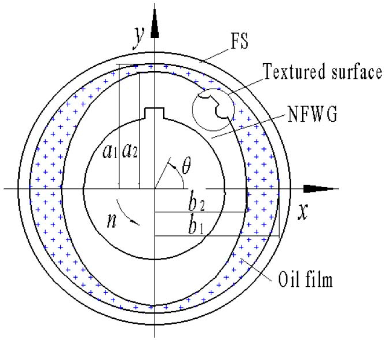
Figure 1 shows the fluid domain model of the ESPs. The parameters of the friction pair are a1 = 25 mm, b1 = 24.7 mm, a2 = 24.9 mm, and b2 = 24.4 mm. The coordinate system origin is located at the geometric center of the NFWG and FS. The x and y axes represent the short and long axes of the ellipse, respectively, and the z axis represents the width direction of the NFWG and FS, where z = 0 corresponds to the half-width position. The NFWG rotates counterclockwise at the speed of n. The boundary of fluid film includes the outer contour surface of the NFWG and the wall of the FB. At the NFWG angle θ = 0, the maximum value of fluid film thickness h(θ) is hmax. At θ = 90°, the fluid film thickness h(θ) is at its minimum value hmin. The outer contour surface of the NFWG is textured with spherical cap dimples.

Figure 1.
Model of the friction pairs between the NFWG and FS.
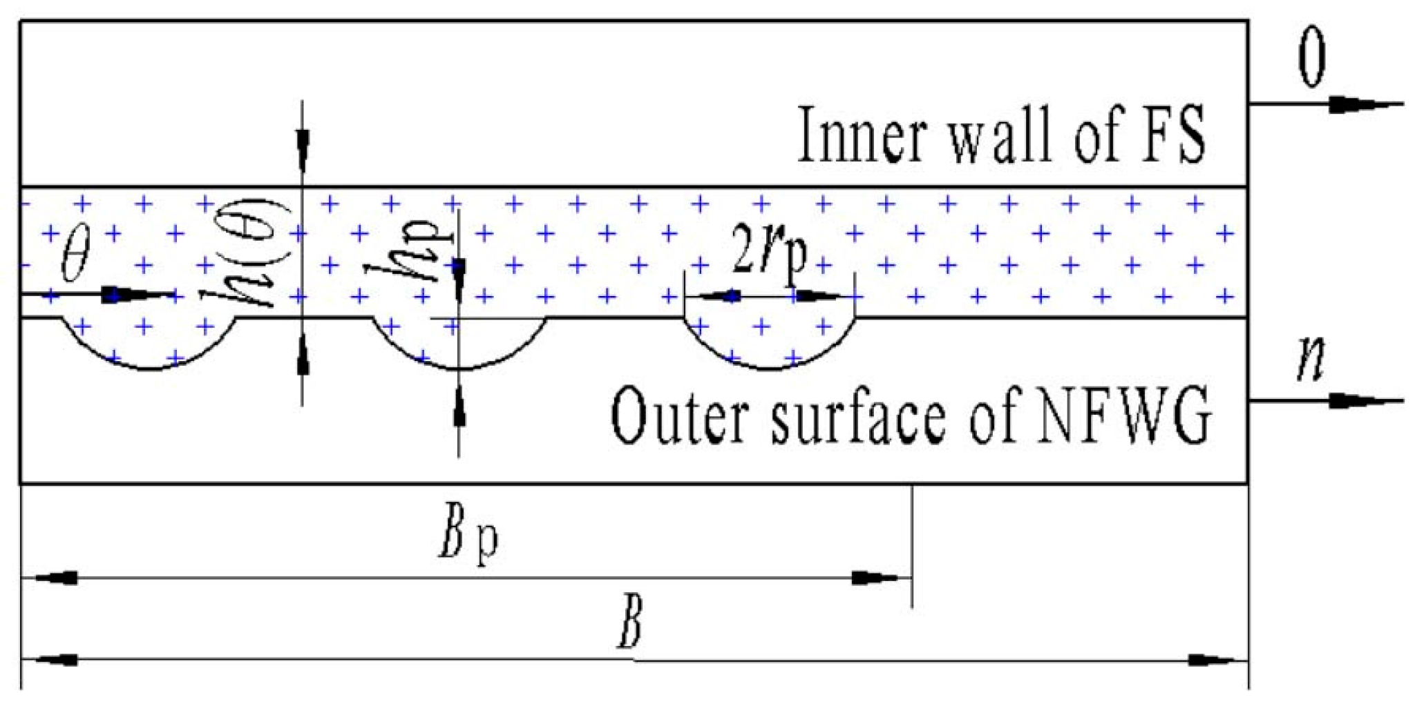
The parameters of the spherical cap dimple texture include the distribution area, depth, radius, and density. As shown in Figure 2, hp is the texture depth, rp is the radius of the dimple, Bp is the distribution length of the texture along the circumferential direction of the elliptical outer contour surface of the NFWG, B is the unfolded length of the elliptical outer contour surface of the NFWG along the circumferential direction, and L is the width of the NFWG.

Figure 2.
Unfolded diagram of the cross-section of the elliptical outer contour rim of the NFWG.
2.2. Numerical Models
The fluid domain model of the ESPs is established using ANSYS FLUENT to investigate the effects of the surface texture structural parameters of the NFWG on the lubrication performances of the ESPs in the HD without a FB. The oil film region is the computational domain for the simulation. The analysis type of the geometry is “3D”, with a model width of 20 mm in the z-direction. The finite element analysis is solved under steady state, considering the effect of gravity.
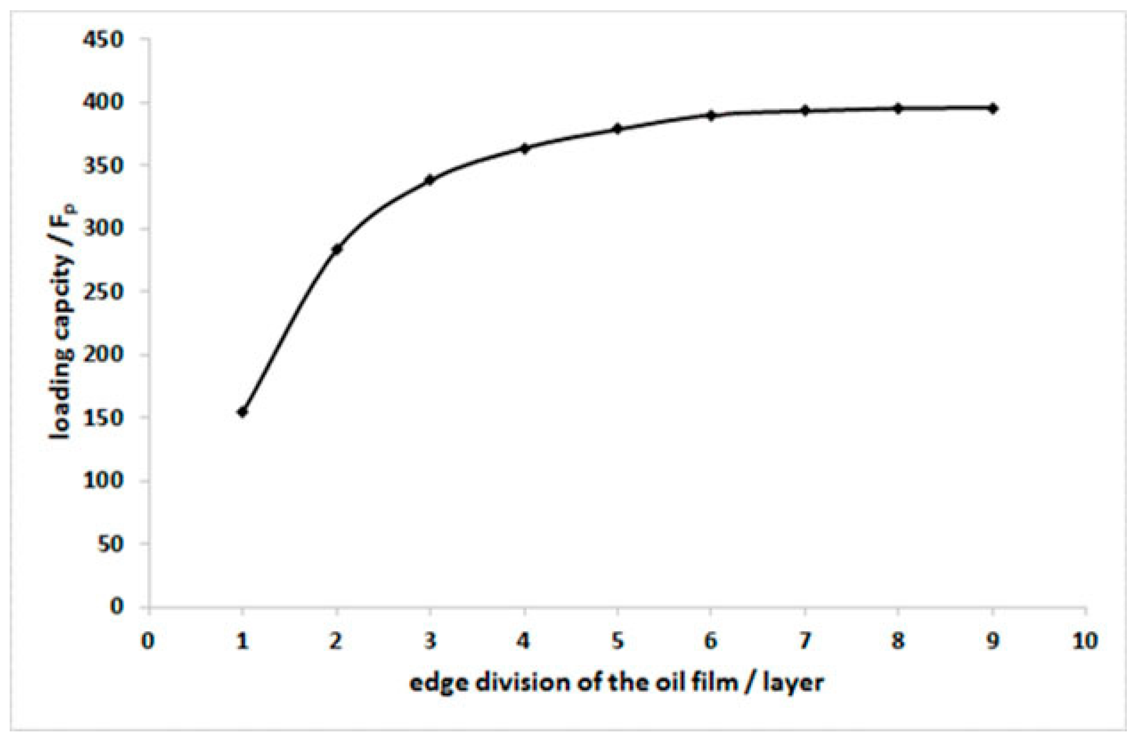
In the friction pairs, the oil film thickness is relatively small compared to the diameter of the FS. The scale of the fluid domain varies greatly in the circumferential direction but relatively less in the radial direction. Therefore, the mesh is refined in the circumferential direction, while moderately increasing the element size in the radial direction. The hexahedral mesh is used in Fluent, and the “edge sizing” method is applied to set the element size and count [29]. The model is divided into 360 layers in the circumferential direction and 10 layers in the axial direction. Because the thickness of the oil film is very small, the grid size across the oil film has a great influence on the accuracy of the results. To analyze the grid independence, it is divided into different numbers of grid layers across the oil film from 1 to 9 in ANSYS Fluent. The relationship between the loading capacity and the number of grid layers is shown in Figure 3. It can be seen that as the number of layers increases, the loading capacity tends to be constant, indicating that the simulated results at this time have nothing to do with the number of grids. To ensure the accuracy of the results and reduce the number of calculations, it is divided into six layers across oil film. The total number of cells is 21,600.
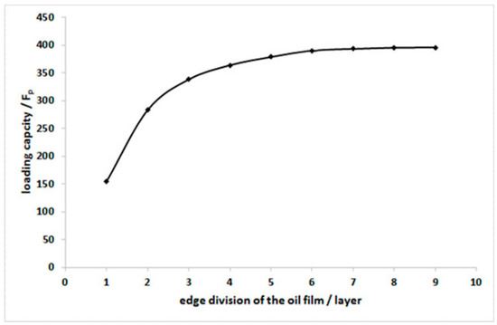
Figure 3.
The relationship between the loading capacity and the number of grid layers across the oil film.
The viscosity grade of the lubricating grease used is NLGI 2, and its viscosity characteristics conform to the Herschel–Bulkley model. The parameters [30,31] of the lubricating grease are as follows: the density of the grease is 930 kg/m3, the grease consistency is 20.6 Pa∙sn, the power law index is 0.605, the yield stress is 650 Pa, and the shear rate is 32 s−1. The rotational speed of the WG is 2000 rpm, the elliptical gap ratio δ is 3, and the operating pressure is 101,325 Pa.
The boundary condition settings include “pressure inlet”, “pressure outlet”, and zero gauge pressure. The two positions with the maximum fluid film thickness are uniformly distributed in the circumferential direction. Both sides of θ = 0° and θ = 180° are set as the pressure inlets, and the outlets are located on both sides of the end face. The fluid domain changes dynamically with boundary motion. Thus, the “dynamic mesh” model is used to simulate fluid flow, combining the use of the “smoothing” and “remesh” methods to update the mesh. The “pressure-based” solver is chosen for numerical analysis. The “SIMPLE” algorithm is used to handle pressure–velocity coupling, and the “second-order upwind” scheme is applied to discretize the momentum equation. The pressure difference format is set to “PRESTO!”. To achieve higher accuracy, all residual terms use a convergence tolerance of 10−6, and the number of iterations is 200.
3. Results
3.1. Effect of Texture Distribution Area
This study investigates the effect of three different texture distributions, that is full-area distribution, convergent-area distribution, and divergent-area distribution, on the lubrication characteristics of the ESPs. When the texture is uniformly distributed on the entire outer contour surface of the NFWG, it is a full-area distribution. When the texture is located only within the convergent region of the friction pair gap on the outer contour surface of the NFWG, it is a convergent-area distribution. When the texture is located in the divergent region of the friction pair gap on the outer contour surface of the NFWG, it is a divergent-area distribution.
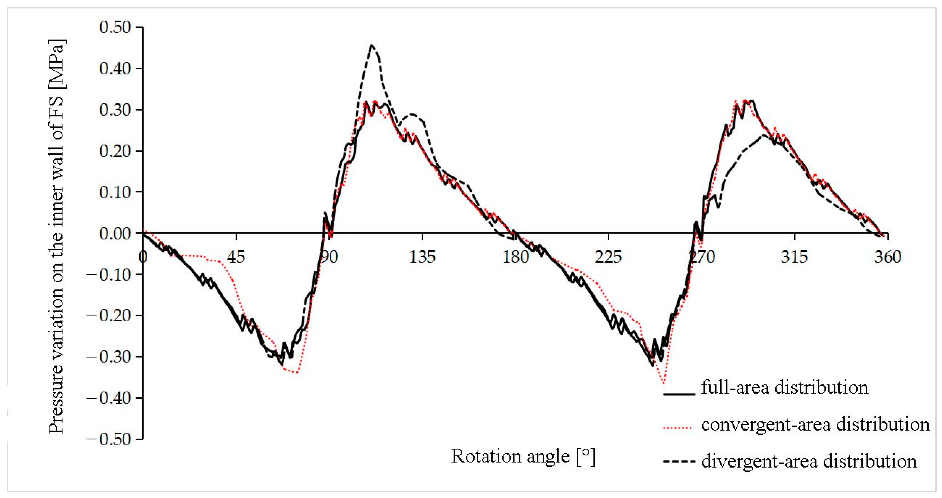
Under the conditions of z = 0, δ = 3, hmin = 0.1 mm, n = 2000 rpm, and hp = rp = 1 mm, the variation curves of the lubricant film pressure on the wall of the FB with different micro-dimple texture distribution conditions as the NFWG rotates are shown in Figure 4. Compared to a full-area distribution and convergent-area distribution, the lubricant film pressure distribution on the inner wall of the FS is smoother while the texture follows the divergent-area distribution. Under both conditions of convergent-area and divergent-area distributions, there are sharp regions in the oil film pressure distribution curve at the maximum positive pressure and maximum negative pressure points.
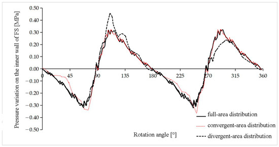
Figure 4.
Variation of lubricant film pressure on the wall of the FB under full-area distribution, convergent-area distribution, and divergent-area distribution of the texture.
Under convergent-area distribution and full-area distribution, the pressure curves are very close, with the positive pressure region curves almost overlapping. Under the full-area distribution condition, the pressure variation in the positive and negative pressure regions remains more stable as the NFWG rotates. The local fluctuations observed in the lubricant film pressure curve represent the hydrodynamic lubrication effect induced by the localized micro-dimple texture on the outer contour surface of the NFWG.
Under different texture depths and texture distribution regions, the maximum pressure of lubricant film Pmax, load-carrying capacity Fp, and frictional resistance Ff of the ESPs are shown in Table 1. The data in Table 1 indicate that while the texture is distributed in the convergent region, the ESP load capacity is similar to that under the full-area distribution condition. However, the friction force is the highest among the three distribution regions in this case, which leads to the deterioration in lubrication performance. For the divergent-area distribution and convergent-area distribution, the friction force is similar. Although the load capacity is relatively high under these conditions, the friction force increases significantly, which results in the reduction in lubrication performance compared to the full-area distribution.

Table 1.
Maximum oil film pressure Pmax, load capacity Fp, and friction force Ff under different texture depths and texture distribution conditions.
3.2. Effect of Texture Depth
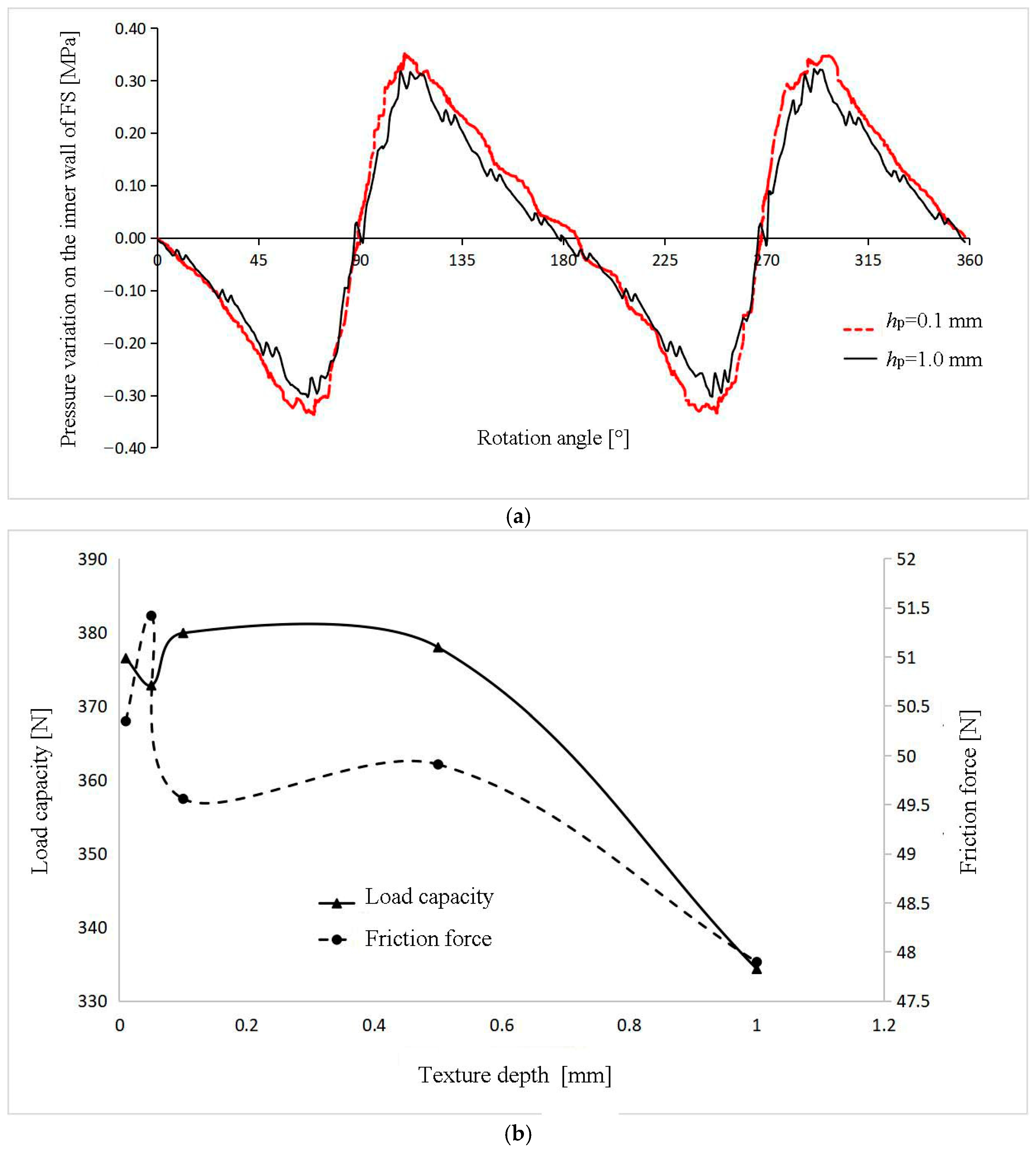
While the micro-dimple texture exhibits a full-area distribution, under the conditions of z = 0, δ = 3, hmin = 0.1 mm, and n = 2000 rpm, Figure 5a shows the pressure distribution curves of lubricant film on the wall of the FS for the texture depths hp of 0.1 mm and 1 mm. The simulation indicates that the lubricant film pressure distribution curve for a texture depth of 0.1 mm is smoother compared to that for a texture depth of 1 mm. In addition, the load capacity is slightly higher, and the local saw tooth fluctuations on the curve are significantly reduced. The data in Table 1 also show that the friction force is smaller for a texture depth of 0.1 mm, while the load capacity is higher.
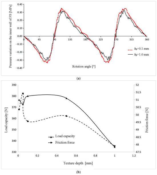
Figure 5.
Effects of texture depth on (a) the pressure distribution relative to the NFWG rotation at a depth of 0.1 mm and 1 mm, and (b) the capacity and friction force at depth in the range of (0, 1) mm.
Under the conditions of δ = 3, hmin = 0.1 mm, and n = 2000 rpm, with the micro-dimple texture exhibiting a full-area distribution, the curves of load capacity and friction force of the ESPs with varying texture depths are shown in Figure 5b. Figure 5b shows that the load capacity and lubrication performance of the ESPs are significantly influenced by the depth of the micro-dimple texture. When the texture depth varies, both the oil film load capacity and friction force change substantially. When the depth exceeds the gap scale between the friction pairs, the ESP load capacity decreases sharply. At the scale of texture depth in this study, an optimal depth of 0.1 mm for the micro-dimple texture is identified, at which the oil film load capacity is maximized, while the friction force is minimized.
3.3. Effect of Texture Shape
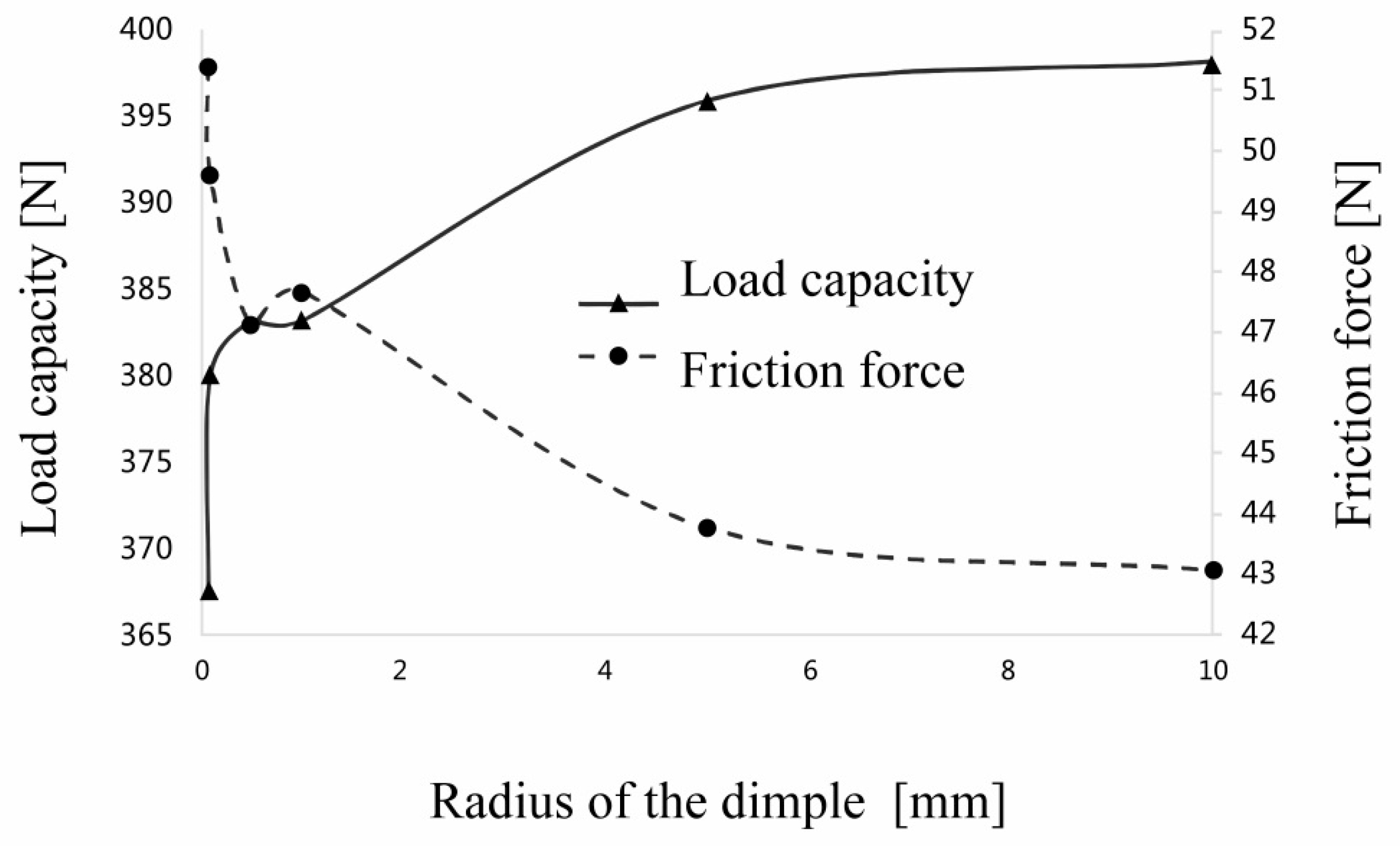
The ratio of rp to hp can characterize the shape of the texture on the outer contour surface of the NFWG. The following section analyzes the effect of different micro-dimple shapes, load capacities, and friction forces on the pressure distribution. A smaller ratio of rp/hp indicates smaller dimples, whereas a larger ratio indicates the opposite. Under the conditions of δ = 3, hmin = 0.1 mm, n = 2000 rpm, and hp = 0.1 mm, with the micro-dimple texture exhibiting a full-area distribution, the variation curves of load capacity and friction force with rp are shown in Figure 6.
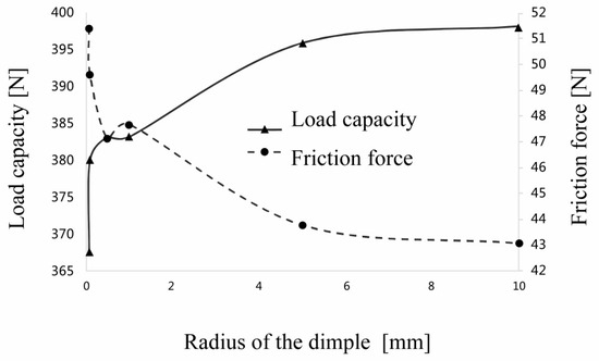
Figure 6.
Variation curves of the load capacity and friction force with respect to the radius of the dimple.
Figure 6 shows that the load capacity decreases sharply as rp approaches 0, while the friction force increases drastically. As rp increases, the load capacity improves, and the friction force decreases. When rp exceeds 6 mm, both the load capacity and friction force stabilize with minimal further change. There is an optimal value for rp at 6 mm.
3.4. Effect of Texture Density
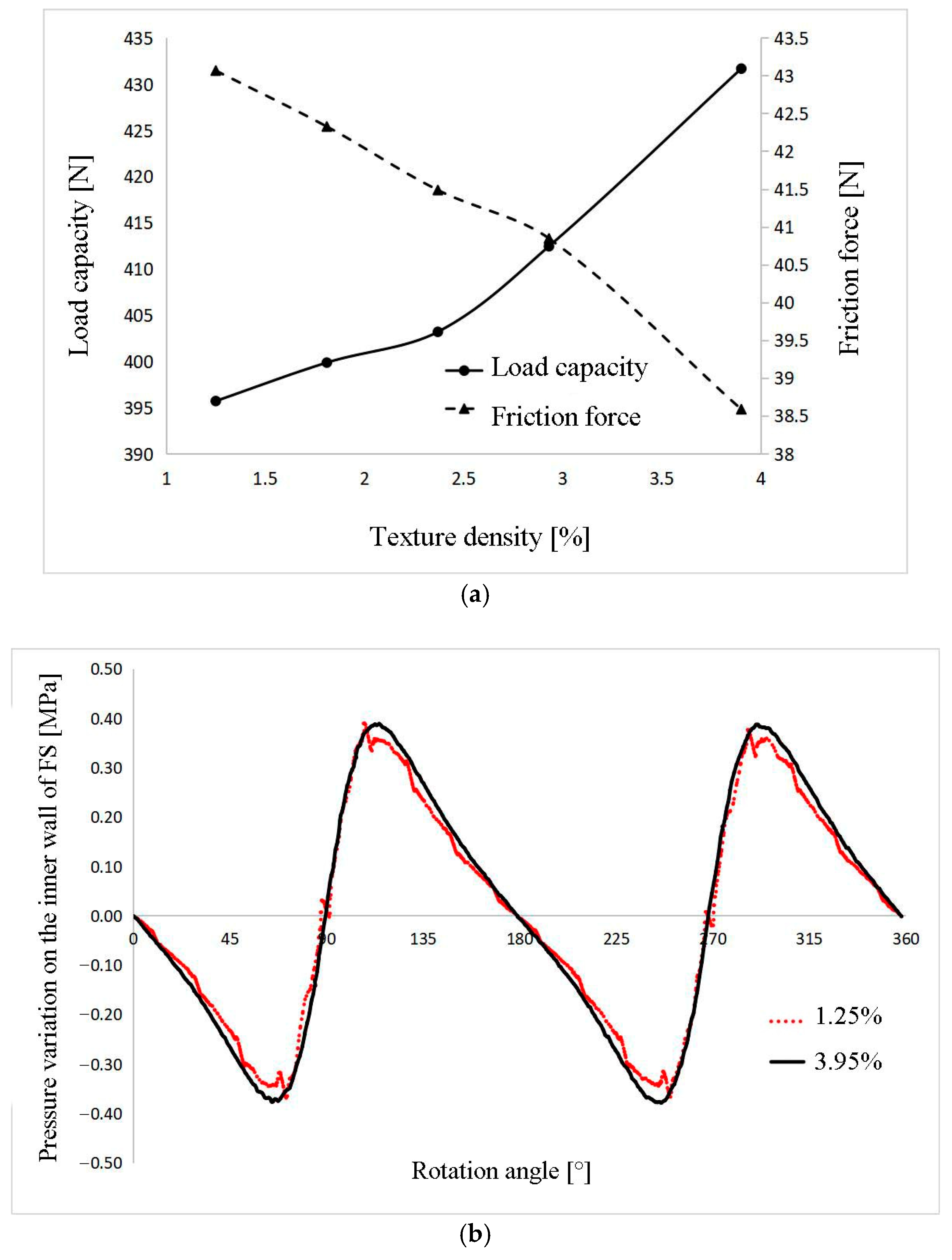
The ratio can represent the density of the micro-dimple texture on the surface of the outer contour surface of the NFWG, where N is the number of micro-dimples, is the area of a single micro-dimple, and BL is the unfolded area of the elliptical outer contour surface of the NFWG. The larger the ratio is, the higher the density of the micro-dimple texture on the outer contour surface of the NFWG. Under the conditions of hmin = 0.1 mm, δ = 3, n = 2000 rpm, hp = 0.1 mm, and rp = 6 mm with the micro-dimple texture exhibiting a full-area distribution, the variation curves of the load capacity and friction force with respect to the texture density are shown in Figure 7a.

Figure 7.
Effect of texture density on (a) the load capacity and friction force, and (b) the distribution curve of the oil film pressure on the inner wall of the FS at texture densities of 1.25% and 3.9%.
Figure 7a shows that the load capacity increases and the friction force decreases as the density of the micro-dimple texture increases. Based on Figure 7a, two different micro-dimple texture density values of 1.25% and 3.95% are selected, and the lubricant film pressure on the wall of the FB with respect to the rotational angle of the NFWG is shown in Figure 7b. Figure 7b indicates that the pressure value increases and the curve becomes smoother as the density of the micro-dimple texture increases.
4. Discussion
Compared to the convergent-area distribution and divergent-area distribution, the micro-dimple texture has better load capacity and lubrication performance under the full-area distribution condition on the outer contour surface of the NFWG. Considering the bidirectional operation characteristics of the HD, the texture on the outer contour surface of the NFWG must adopt the full-area distribution.
The load capacity and lubrication performance of the ESPs between the FS and NFWG are greatly influenced by the texture depth. Under the scale of the HD in present study, when the texture depth is 0.1 mm, the load capacity of oil film is maximized, while the friction force is minimized. Within the range of 0–10 mm, when the radius rp is greater than 6 mm, the trend of increasing load capacity and decreasing friction tends to flatten out.
As the density of the micro-dimple texture increases, the load capacity of the oil film increases, while the friction force decreases. The distribution density of the micro-dimple texture needs to be determined based on factors such as the HD specifications, load capacity requirements, processing technology, and economic considerations.
The commonly used lubricants for HD are grease, lubricating oil, and solid lubricants. The commonly used lubricating grease is lithium-based or calcium-based grease, and further research is needed on how different viscosity lubricants or additives interact with parameters, such as texture depth, etc.
5. Conclusions
This study investigates the effect of the micro-dimple texture parameters on the outer contour surface of the NFWG on the load-carrying capacity and the frictional resistance of the lubricant film in the ESPs between the FS and NFWG in the HD without a FB.
The research results of this paper indicate that when designing ESPs with a micro-dimple texture in the HD without a flexible bearing, the following parameters yield better lubrication performance: an optimal clearance ratio of 3, a full-area distribution of the texture on the outer surface of the NFWG, a depth of 0.1 mm, a radius of 6 mm, and a distribution density of 3.9%.
This study provides a reference for the practical design of ESPs in the HD without a FB, which is significant for improving the load capacity and lubrication performance of ESPs and extending the service life of the HD under extreme transmission conditions.
Author Contributions
Conceptualization, H.X. and Z.Y.; methodology, H.X. and Z.Y.; software, Z.Y.; formal analysis, Z.Y. and H.X.; investigation, Z.Y. and H.X.; resources, H.X.; data curation, Z.Y.; writing—original draft preparation, Z.Y.; writing—review and editing, H.X. and Z.Y.; visualization, Z.Y. and H.X.; project administration, H.X.; funding acquisition, H.X. All authors have read and agreed to the published version of the manuscript.
Funding
This research received no external funding.
Data Availability Statement
All data generated or analyzed in this study are included in this published article.
Conflicts of Interest
The authors declare no conflicts of interest. The funders had no role in the design of the study; in the collection, analyses, or interpretation of data; in the writing of the manuscript; or in the decision to publish the results.
References
- Gachot, C.; Rosenkranz, A.; Hsu, S.M.; Costa, H.L. A Critical Assessment of Surface Texturing for Friction and Wear Improvement. Wear 2017, 372–337, 21–41. [Google Scholar] [CrossRef]
- Etsion, I. Surface Texturing For In-cylinder Friction Reduction. In Tribology and Dynamics of Engine and Powertrain: Fundamentals, Applications and Future Trends; Rahnejat, H., Ed.; Woodhead Publishing: Sawston, UK, 2010; pp. 458–470e. [Google Scholar]
- Morris, N.J.; Shahmohamadi, H.; Rahmani, R.; Rahnejat, H.; Garner, C.P. Combined Experimental and Multiphase Computational Fluid Dynamics Analysis of Surface Textured Journal Bearings in Mixed Regime of Lubrication. Lubr. Sci. 2018, 30, 161–173. [Google Scholar] [CrossRef]
- Gu, C.X.; Meng, X.H.; Xie, Y.B.; Yang, Y.M. Effects of Surface Texturing on Ring/Liner Friction Under Starved Lubrication. Tribol. Int. 2016, 94, 591–605. [Google Scholar] [CrossRef]
- Ran, H.; Liu, D.; Wang, S. A Numerical Wear Simulation Method of Reciprocating Seals with a Textured Rod. Materials 2020, 13, 4458. [Google Scholar] [CrossRef]
- Tagawa, N.; Bogy, D.B. Air Film Dynamics for Micro-Textured Flying Head Slider Bearings in Magnetic Hard Disk Drives. J. Tribol. Trans. 2002, 124, 568–574. [Google Scholar] [CrossRef]
- Blatter, A.; Maillat, M.; Pimenov, S.M.; Shafeev, G.A.; Simakin, A.V.; Loubnin, E.N. Lubricated Sliding Performance of Laser-Patterned Sapphire. Wear 1999, 232, 226–230. [Google Scholar] [CrossRef]
- Nam, P.S.; Mohsen, M.; Phillip, S.H. Control of Friction. Wear 1994, 175, 151–158. [Google Scholar]
- Ranjan, R.; Lambeth, D.N.; Tromel, M.; Goglia, P.; Li, Y. Laser Texturing for Low-Flying-Height Media. J. Appl. Phys. 1991, 69, 5745–5747. [Google Scholar] [CrossRef]
- Wang, X.L.; Liu, W.; Zhou, F.; Zhu, D. Preliminary Investigation of the Effect of Dimple Size on Friction in Line Contacts. Tribol. Int. 2009, 42, 1118–1123. [Google Scholar] [CrossRef]
- Steinhoff, K.; Rasp, W.; Pawelski, O. Development of Deterministic-Stochastic Surface Structures to Improve the Tribological Conditions of Sheet Forming Processes. J. Mater. Process. Technol. 1996, 60, 355–361. [Google Scholar] [CrossRef]
- Yu, T.H.; Sadeghi, F. Groove Effects on Thrust Washer Lubrication. J. Tribol. 2001, 123, 295–304. [Google Scholar] [CrossRef]
- Scaraggi, M.; Mezzapesa, F.P.; Carbone, G.; Ancona, A.; Tricarico, L. Friction Properties of Lubricated Laser-MicroTextured-Surfaces: An Experimental Study from Boundary- to Hydrodynamic- Lubrication. Tribol. Lett. 2013, 49, 117–125. [Google Scholar] [CrossRef]
- Andersson, P.; Koskinen, J.; Varjus, S.; Gerbig, Y.; Haefke, H.; Georgiou, S.; Zhmud, B.; Buss, W. Microlubrication Effect by Laser-Textured Steel Surfaces. Wear 2007, 262, 369–379. [Google Scholar] [CrossRef]
- Lu, P.; Wood, R.J. Tribological Performance of Surface Texturing in Mechanical Applications-A Review. Surf. Topogr. Metrol. Prop. 2020, 8, 043001. [Google Scholar] [CrossRef]
- Rahmani, R.; Rahnejat, H. Enhanced Performance of Optimised Partially Textured Load Bearing Surfaces. Tribol. Int. 2018, 117, 272–282. [Google Scholar] [CrossRef]
- Meng, F.M.; Zhou, R.; Davis, T.; Cao, J.; Wang, Q.J.; Hua, D.; Liu, J. Study on Effect of Dimples on Friction of Parallel Surfaces under Different Sliding Conditions. Appl. Surf. Sci. 2010, 256, 2863–2875. [Google Scholar] [CrossRef]
- Vlădescu, S.C.; Medina, S.; Olver, A.V.; Pegg, I.G.; Reddyhoff, T. Lubricant Film Thickness and Friction Force Measurements in A Laser Surface Textured Reciprocating Line Contact Simulating the Piston Ring–Liner Pairing. Tribol. Int. 2016, 98, 317–329. [Google Scholar] [CrossRef]
- Walker, J.C.; Kamps, T.J.; Lam, J.W.; Mitchell-Smith, J.; Clare, A.T. Tribological Behaviour of An Electrochemical Jet Machined Textured Al-Si Automotive Cylinder Liner Material. Wear 2017, 376–377 Pt B, 1611–1621. [Google Scholar] [CrossRef]
- Qiu, M.; Delic, A.; Raeymaekers, B. The Effect of Texture Shape on the Load-Carrying Capacity of Gas-Lubricated Parallel Slider Bearings. Tribol. Lett. 2012, 48, 315–327. [Google Scholar] [CrossRef]
- Etsion, I. State of the Art in Laser Surface Texturing. J. Tribol. 2005, 127, 248–253. [Google Scholar] [CrossRef]
- Jia, H.; Xin, H. Study on Lubrication Characteristics of Novel Forced Wave Generator of Harmonic Drive without Flexible Bearing. Materials 2022, 15, 215. [Google Scholar] [CrossRef] [PubMed]
- Ivannov, M.N. Harmonic Drive; National Defence Press: Beijing, China, 1987. [Google Scholar]
- Xin, H.B.; He, H.Y.; Xi, J.R. Research on Meshing Stiffness of Harmonic Drive. Opt. Precision Eng. 1997, 5, 26–29. [Google Scholar]
- Shen, Y.W.; Ye, Q.T. Theory and Design of Harmonic Drive; China Machine Press: Beijing, China, 1985. [Google Scholar]
- Xin, H.B. Fracture Strength Analysis of Flexspline Materials Applied Frequently. J. Changchun Inst. Opt. and Fine Mech. 1998, 21, 65–67. [Google Scholar]
- Wang, X.; Shao, F.X.; Yuan, H.X. Structure and Mold Design of Plastic Flexible Wheels. China Plas. 2016, 30, 100–104. [Google Scholar]
- Wu, K.C.; Liu, J.W.; Zhang, Z.B.; Wang, S.B.; Hu, X.Q. Study on Harmonic Gear Reducer From Engineering Plastics. China Plas. 1993, 7, 30–35. [Google Scholar]
- Gertzos, K.P.; Nikolakopoulos, P.G.; Papadopoulos, C.A. CFD analysis of journal bearing hydrodynamic lubrication by Bingham lubricant. Tribol. Int. 2008, 41, 1190–1204. [Google Scholar] [CrossRef]
- Westerberg, L.G.; Sarkar, C.; Lladós, J.F.; Lundström, T.S.; Höglund, E. Lubricating Grease Flow in a Double Restriction Sealgeometry: A Computational Fluid dynamics Spproach. Tribol. Lett. 2017, 65, 82. [Google Scholar] [CrossRef]
- Li, J.X.; Westerberg, L.G.; Höglund, E.; Lugt, P.M.; Baart, P. Lubricating Grease Shear Flow and Boundary Layers in a Concentric Cylinder Configuration. Tribol. Trans. 2014, 57, 1106–1115. [Google Scholar] [CrossRef]
Disclaimer/Publisher’s Note: The statements, opinions and data contained in all publications are solely those of the individual author(s) and contributor(s) and not of MDPI and/or the editor(s). MDPI and/or the editor(s) disclaim responsibility for any injury to people or property resulting from any ideas, methods, instructions or products referred to in the content. |
© 2025 by the authors. Licensee MDPI, Basel, Switzerland. This article is an open access article distributed under the terms and conditions of the Creative Commons Attribution (CC BY) license (https://creativecommons.org/licenses/by/4.0/).