Friction of Tungsten-Based Coatings of Steel under Sliding Contact †

Naval Air Warfare Center Aircraft Division, Joint-Base McGuire-Dix-Lakehurst, Lakehurst, NJ 08733, USA
†
NAVAIR Public Release 2018-609 Distribution Statement A—“Approved for public release; distribution is unlimited”.
Lubricants 2019, 7(2), 14; https://doi.org/10.3390/lubricants7020014
Submission received: 6 December 2018
/
Revised: 24 January 2019
/
Accepted: 28 January 2019
/
Published: 31 January 2019
(This article belongs to the Special Issue Adhesion, Friction and Lubrication of Viscoelastic Materials)
Abstract
:An investigation was made to determine the effects of tungsten surface coating on the coefficient of friction of sliding contact between lubricated steel surfaces. The four-ball test was modified, using a tungsten carbide ball bearing in the spindle to cause sliding contact onto three hard steel ball bearings coated with tungsten disulfide lamellar dry lubricant coating, with a coating of grease lubrication applied to the ball bearings. The coatings, loads, speed, and grease level were varied to best understand the impact of different conditions on the friction coefficient.
1. Introduction
The ability to reduce the coefficient of friction (COF) during sliding contact between two steel surfaces is a capability with numerous applications in mechanical engineering design. Often (but not exclusively) friction is desired to be minimized between two surfaces in sliding contact, as friction can cause a reduction in mechanical efficiency, physical, and material damage to the surfaces, as well as result in damaging heat from friction energy losses. Metals are unique for having a high non-lubricated friction coefficient, and lubricants including oils, greases, and dry surface coatings [1,2,3,4,5,6,7,8,9,10,11,12,13] are often used to reduce the friction during sliding contact.
Often in engineering, a hard-steel surface will be coated with tungsten carbide (WC) [14,15,16,17,18,19,20,21,22,23], applied as a surface treatment, often using High Velocity Oxygen Fuel (HVOF) to apply the WC coating as described in the standard AMS2448A [24]. The WC coating serves to protect the steel surface. Inherently, WC is harder than steel; it has a Young’s modulus of (typically) 500–700 GPa, significantly higher than the 200 GPa for steel. With this increased stiffness, there is less expected deformation of the surface, and thus, due to the pattern of random asperities within the surface, the true contact area (Figure 1) is reduced. As the friction force is determined as the product of the shear stress and the true contact area [25,26,27,28]
the WC coating will reduce the COF marginally due to reduced true contact area. This has been observed in published [29] COF for non-lubricated steel–steel contact (COF = 0.8) versus steel–WC contact (COF = 0.6).
The second important surface treatment is the coating of tungsten disulfide , a soft lamellar material similar to graphite/ [30,31,32,33,34]. Solid lubrications by lamellar solids is commonly used when liquid lubricants are impractical, such as in clean rooms, vacuum conditions, extreme temperatures, and in outer space. Lamellar solids are defined as solids with a repeating molecular pattern, effectively sheets of molecules [25]. Because of this structure, they often have anisotropic properties.
The most commonly used lamellar solids for solid lubrication are graphite and molybdenum disulfide [35]; tungsten disulfide operates on a very similar principle. One principle of the thin film approach is to have a soft coating separating two hard objects in contact. When two objects are both hard and inflexible, there is inherently little true contact area. The true contact area is defined as the actual area of metal-on-metal contact (Figure 1). Even the smoothest surfaces have some asperities and random surface roughness, and with less elastic deformation there is less true metal-on-metal contact. Two hard surfaces in dry contact will have a small true contact area (m), but the shear stress (Pa) will inherently be higher for hard materials, and thus, the friction force will be high. The opposite of this can happen with a hard object and a soft object; the shear stress is reduced but the true contact area is much higher, and therefore there is a large friction force. By applying a thin film of a soft material, the hard material underneath prevents significant deflection, and thus, decreasing the true contact area, all the while the soft film has a low shear stress from sliding contact with a hard metal substance. This low true contact area and low shear stress result in a low friction force and reduced coefficient of friction.
Lamellar solids such as are defined as solids with a repeating molecular pattern, effectively sheets of molecules. Because of this structure, they often have anisotropic properties. Other noteworthy characteristics of using lamellar solids are their anisotropic properties; they will easily deform in very low shear stress from the surfaces of contact, yet remain attached to the worn surface. This will allow for low shear stresses during sliding contact, and if the coating is thin and unable to deform much from the worn surfaces, the true contact area will be minimal even with a hard surface sliding against it.
Finally, oils and greases are often used as lubricants as well during sliding contact. Liquid lubricants of varying viscosities serve to coat the metal surfaces, and protect the surfaces by forming a lubricant film [36,37,38], and only the more-profound asperities can exceed the film thickness height and be worn in metal-on-metal contact. At high enough pressures, the lubricant ceases to be a Newtonian fluid, and the contact enters the elasto-hydrodynamic domain [25,28,39,40,41,42,43], where the viscosity increases dramatically due to pressures, and the surfaces flatten due to high pressures. As a result, a minimum film thickness at the interface can be expected, protecting surface asperities and reducing the true contact area (Figure 1) by protecting the surfaces that do not protrude from the film thickness. Grease has its unique challenges in modeling and predicting the film thickness, as grease is a distinct lubricant that is a solid to semi-fluid mixture of a liquid lubricant and a thickening agent [44].
2. Experimental Approach
It is difficult to determine the average COF between two surfaces, and any COF will inherently fluctuate with temperature, load, speed, and random surface asperities. In order to determine the effects of these coatings and grease lubrication for sliding contact, a modified four-ball test will be conducted. The four-ball tester is used for a standard test of lubricants as defined in ASTM D4172 [45] and ASTM D2783 [46] for Extreme Pressure Tests. The four ball test utilizes four 12.7 mm (1/2-inch) diameter G25 ball bearings [47,48,49,50]; three are locked into place in a cup, and the forth is connected to a spindle pressed under a specified load into the 3 lower balls (Figure 2). The lower three balls are coated with the lubricant of interest, which is heated and maintained at a specified temperature. The top ball spins under a specified load, at a specified speed and for a specified duration, until a small circular (typically <1 mm diameter) wear scar appears at the point of contact. The top ball spindle is connected to a load cell to measure the torque, which can determine the friction force and track the COF in real time. The typical settings for the ASTM D4172 are for a load of 392.4 N (40 kg), a speed of 1200 r/min, a lubricant temperature of 74 C, maintained for 60 min; this standard is used to compare the wear and friction properties of different lubricants.
The four-ball test will deviate significantly from the ASTM D4172 standard in order to focus on tungsten-based lubricants. Of primary interest are the coatings; the bottom ball bearings can easily and inexpensively receive a <1 m coating; this lamella coating, under the brand name Dicronite, is used as a commercially available solid lubricant, and has an advertised COF of 0.03 tested with an incline plane test [51]. The steel balls used in the four-ball test have a Rockwell hardness of 64–66.
The WC coating, however, has its own unique challenges as the HVOF requires the part subjected to coating to be held down in place; a unique challenge for a 12.7 mm (1/2-inch) diameter ball bearing. It could not be expected that the ball bearings to get an even coating of WC, and therefore ball bearings of G25 quality made of pure WC will be used instead for the top ball in the spindle; these ball bearings will be supplied by the manufacturer VXB. Because pure WC will inherently be harder than steel, this is expected to result in a slightly lower COF. Finally, trials of standard hard-steel G25 ball bearings will also be used to compare the friction changes with and without the and/or the WC coatings.
The second important consideration is the speed of the test. The friction coefficient is inherently affected by speed; simplified COF tables will list the static and dynamic COF and the static will always be the greater of the two. The impacts from speed are inherently much more complex than simply static and dynamic, as speed affects both the bonding between surfaces as well as the generation of an elastic film thickness when there is a lubricant. In general, the friction coefficient is reduced with higher speeds, as faster speeds often result in thicker lubricant film thickness; this is clearly demonstrated in the Hamrock Dowson’s empirical equation [25,39,44,52,53,54,55,56] for lubricant thickness
where (m) is the minimum film thickness, (m) is the central film thickness, is the dimensionless speed parameter, is the dimensionless material parameter, is the dimensionless load parameter, is the ellipticity of the contact area, (Pa·s) is the dynamic viscosity of the lubricant at atmospheric pressure, (Pa) is the pressure viscosity coefficient, E’ (Pa) is the reduced Young’s modulus, R’ (m) is the reduced radius, W (N) is the load, and U (m/s) is the velocity of sliding contact of the four-ball test
where is the rotation speed in revolutions per minute (r/min) of the four-ball test, and R (m) is the radius of the ball bearing (6.35 mm or 0.25 inch). It is clear that before the pressure and film thickness profile can be realized, it is necessary to determine the dynamic viscosity and the minimum film thickness, so that a proper film thickness function can be realized and the wear rate analyzed. It is clear that as increases, and increase, and thus, the COF will decrease. The typical four-ball test is set to 1200 r/min, and the maximum speed of most machines is 1800 r/min. Throughout the test the speeds will be varied at the ranges of machine speeds, including 200 r/min, 1200 r/min, and 1800 r/min (the range of the machine), to better understand the impact of speed on the friction COF.
Next, the estimated pressure can be used to determine a desired load for the four-ball test. This load is determined with Hertz contact theory [14,15,16] for elastic deformation, where the average and maximum pressure of two identical spheres in elastic contact are
where W (N) is the load and a (m) represents the radius of the circular region of elastic deformation
where R’ (m) is the reduced radius
which is 3.175 mm (0.125 inch) for the four-ball test. The value of E’ (Pa) represents the reduced modulus of elasticity
where is the modulus of elasticity for steel (207 GPa) and p is the dimensionless Poisson’s Ratio for steel (0.3); the reduced Young’s modulus E’ for two steel ball bearings is thus, 227.2 GPa. If the top ball is WC, with a modulus of elasticity of 620 GPa and a Poisson’s Ratio of 0.31, the reduced modulus of elasticity is 454 GPa.
If the average pressure is known, the load can be calculated as
For a four-ball test, the value of W needs to be multiplied by 3 because the load is spread evenly over all three balls being tested.
In general, the friction COF will usually (but not exclusively) decrease modestly with increasing loads, though overall the friction force still increases with increasing load. This makes physical sense, as an increase pressure often results (typically) in an elastic smoothing of surface asperities [57,58,59,60,61,62]. With a lubricant film thickness separating the two surfaces in elasto-hydrodynamic contact, the equivalent viscosity increases exponentially with increasing loads, which limits the true contact area, and reduces the overall increase in shear stress with increasing load.
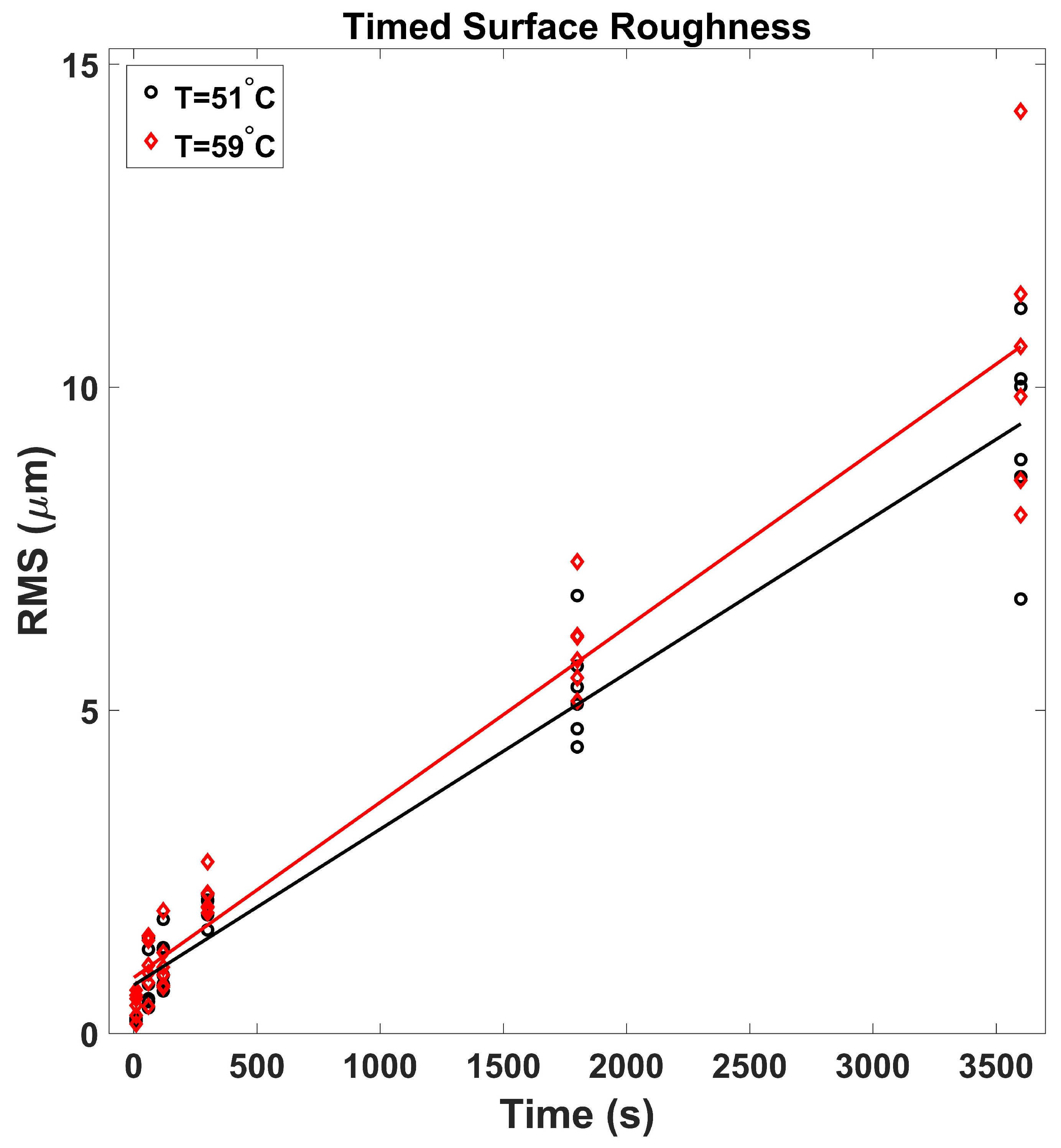
One final source of risk with this test that needs to be recognized and mitigated is the unknown and random nature of the surface roughness [63,64,65]. The ASTM D4172 does not have stringent requirements for the test ball bearing other than a 12.7 mm (1/2-inch) diameter steel bearing with a Rockwell Hardness of 64–66 and a bearing quality of G25, which has a surface roughness maximum of 50.8 nm Ra ≈ 55.88 nm RMS (2.0 -inch Ra ≈ 2.2 -inch RMS). Time-controlled four-ball tests have previously been performed [66], with standard steel ball bearings coated with heavy viscosity mineral oil at both 51 C and 59 C, with a load of 392.4 N, and varying run times of 10 s, 1 min, 2 min, 5 min, 30 min, and 60 min. After each test, the ball bearings were cleaned with both acetone and isopropyl alcohol, and the wear scar was characterized with a Zygo optical profilometer. By deducting the known volume of the 12.7 mm (1/2-inch) diameter ball bearing, a wear scar surface roughness could be determined. Each time was tested twice, with each test yielding three test samples, resulting in six sample surface roughness for each time. Linear trend-lines were generated to determine the increase in surface roughness over time, and at both temperatures the surface roughness increase is linear.
It is clearly observed in Figure 3 with the mineral oil studies that the RMS surface roughness starts at approximately 50.8 nm (2 -inch) for G25 bearings, and increases to 14 m. It is also clear in the data that this increase is linearly proportional to time. The only exception to this is during the first two minutes; friction and wear rates vary significantly due to the phenomenon of running-in [67]. At the conclusion of every test, the wear scars will be measured with an optical profilometer and the surface roughness will be recorded, and tests that have a final surface roughness that significantly exceeds the 3.175 m (125 -inch) surface roughness will be discarded.
3. Test Plan
The test was conducted on an Extreme Pressure (EP) Falex four-ball tester (Serial Number: 1100539). Trials of tests were conducted of steel-on-steel, steel-on- (coated-steel), WC-on-steel, and WC-on- (coated-steel). When the WC was used, it was a single top ball bearing, frequently used twice (flipped over). Mobilith SHC 460 PM synthetic grease was consistently used, where some trials used a light coating of grease; other trials used a heavy amount of grease. The four-ball tester was configured for three different loads, 128 N, 461 N, and 981 N (practical range of the weights for the four-ball machine); these loads were achieved with hanging weights and a lever arm. Every test was run for 900 s of duration, and the friction data was consistently recorded with a sampling of approximately 2–3 Hz. Finally, every test was performed at least twice, to ensure the repeatability of the results.
All of the steel ball bearings were soaked for several days in Heptane () to keep them grease-free. The tungsten carbide balls were cleaned by soaking them in a beaker filled with a mixture of acetone and isopropyl alcohol, and leaving this beaker in a Branson ultrasonic bath for 20 min. It was observed that the coating would visibly appear to come off when the coated ball bearings were rubbed with either acetone or isopropyl alcohol, so a decision was made not to clean the coated ball bearings. This allows for the risk of contaminants, but will accurately reflect the conditions of the coating. An effort was made to consistently wear rubber gloves while handling the coated ball bearings to minimize contamination.
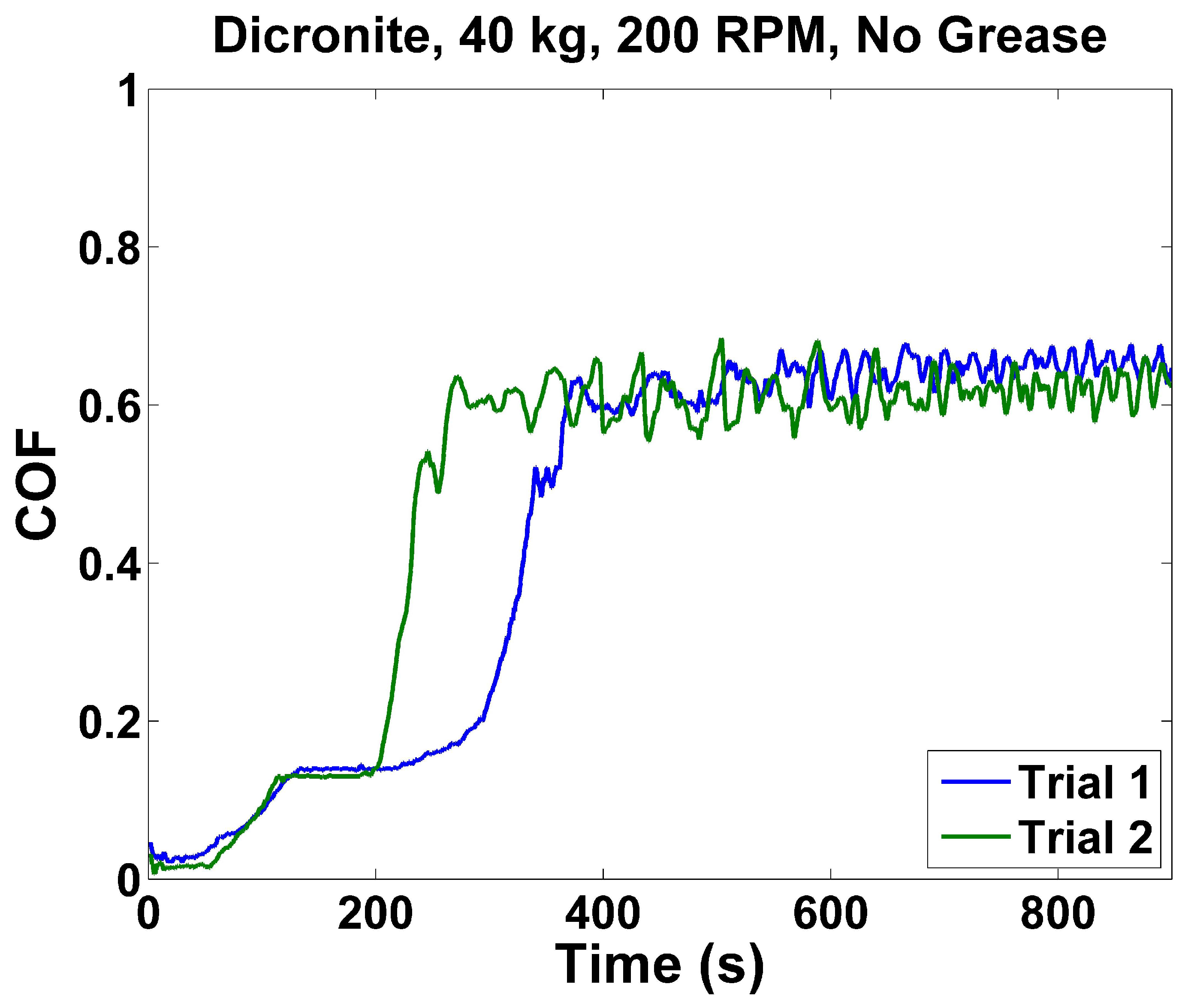
At the beginning of the test, one test (using two repeated trials) of four -coated steel ball bearings was conducted without any grease lubricant. The published COF utilizing the inclined-plane method of DOD-L-85645A [51] yielded a typical COF of 0.03 for unlubricated -on- sliding contact, with a surface roughness no greater than 178 nm (7 -inches) RMS. This -on- test was conducted to verify if this result could be obtained with the four-ball set-up, to validate the four-ball measurements as valid. Two trials were run, with a load of 392 N and a speed of 200 r/min, with no grease at all. In both trials (Figure 4), a low COF of approximately 0.03 was observed for the first minute, then increasing to approximately 0.15 for a few minutes, and finally settling at approximately 0.6 for the duration of the test. This phenomenon is due to the increase in surface roughness that is inherently occurring with continued sliding contact. While individual measurements of COF are very noisy and variable, the lowest average COF over a minute of data collected was 0.0219, observed in the first minute of trial 2, validating this test as a reasonable representation of the COF of sliding friction.
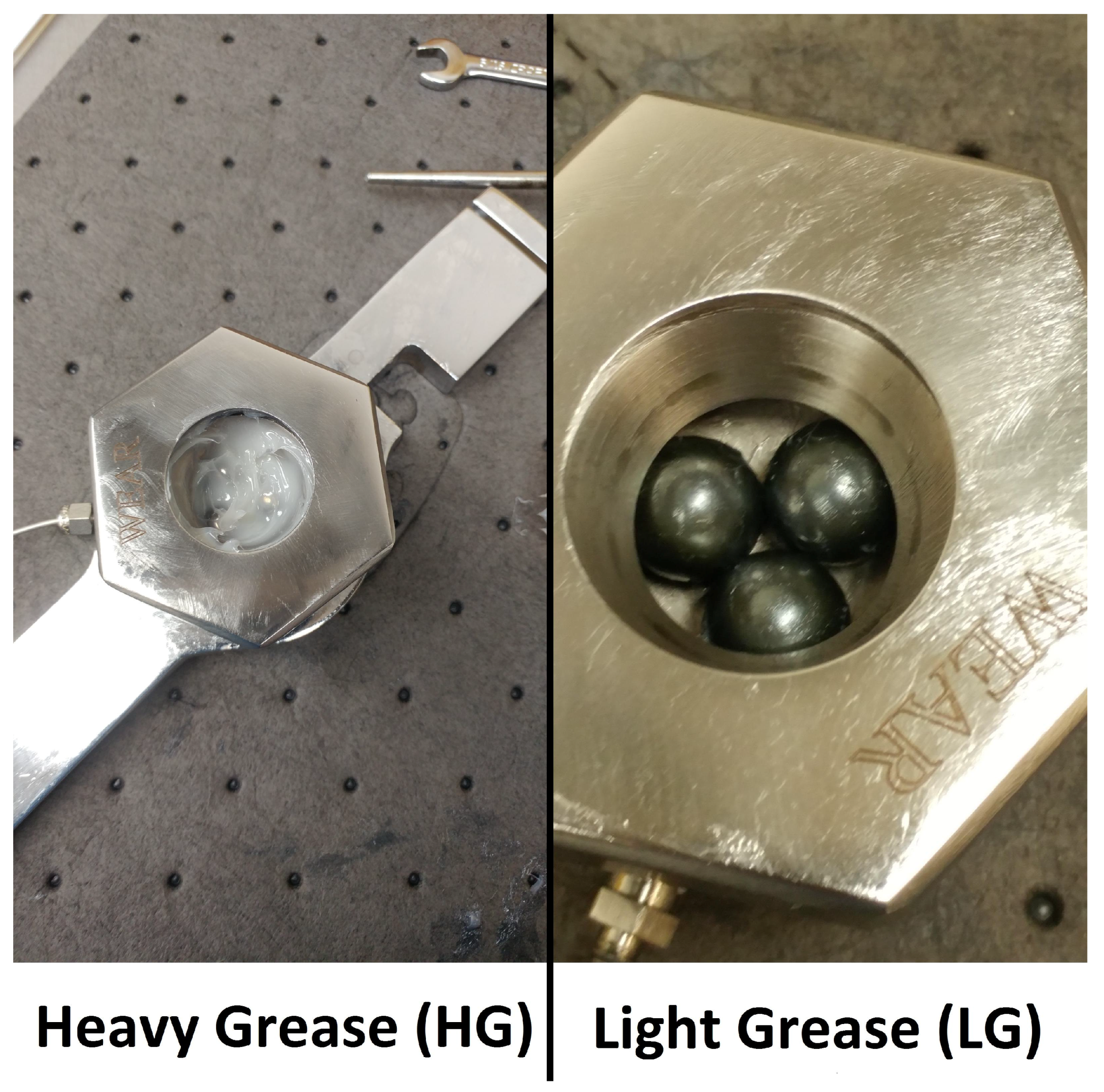
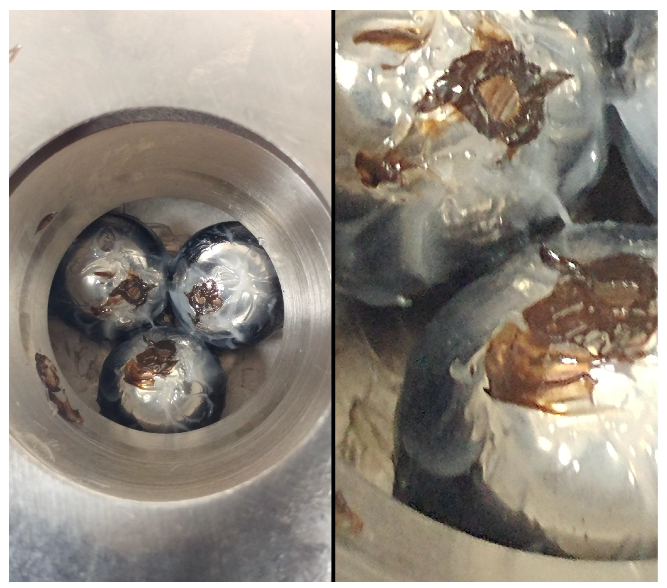
It is not typical for the four-ball test set-up to be used with grease; overwhelmingly the test is used to test different liquid lubricants. To study grease, two configurations were used, Light Grease (LG) and Heavy Grease (HG); see Figure 5. With LG tests, the ball bearings are fully rubbed with an even coating of grease. With the HG tests, heavy globs of grease are spooned into the specimen container, both below the three balls and fully above it, to ensure the ball bearings are fully immersed in grease at all times. Qualitative observations of the LG specimens after a 15 min test demonstrate that the balls remain coated with grease (Figure 6), but it is impossible to truly ascertain whether or not the area of contact remains fully coated during the entire test; it is realistic that there are moments of pure metal-on-metal contact. With the HG test, it can safely be assumed continual coverage of the lubricant over the area of contact.
4. Test Results
4.1. Steel–Steel
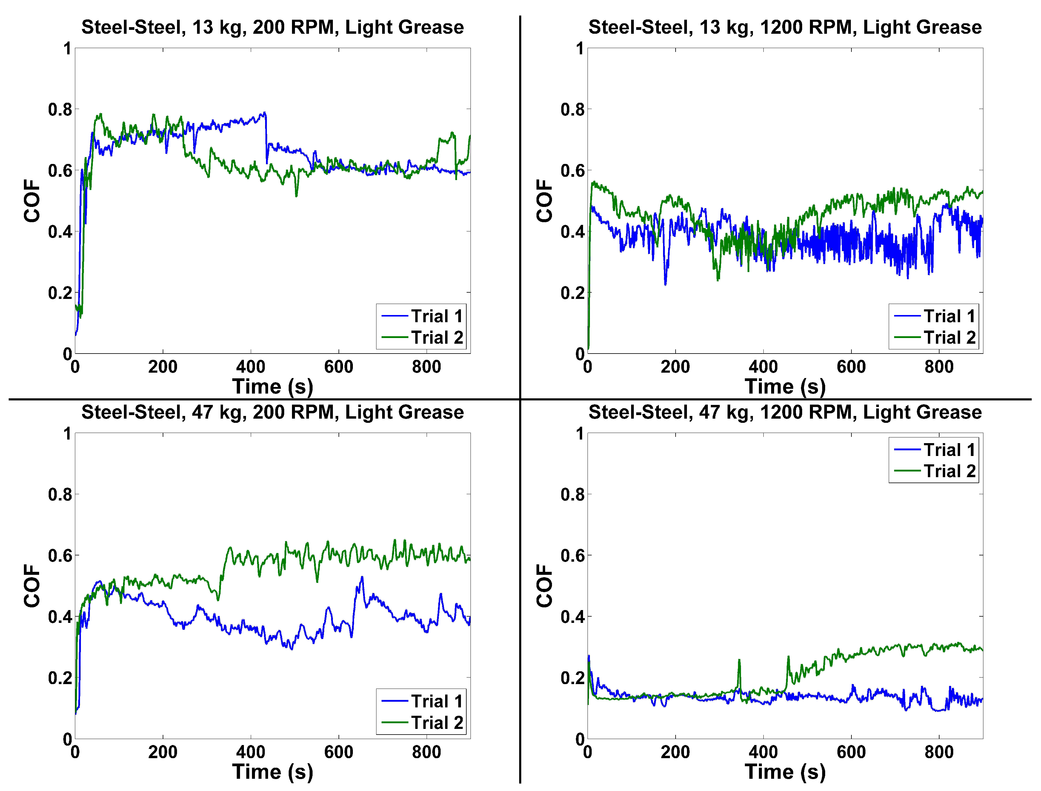
The first series of test utilized the LG configuration steel-on-steel, utilizing the hard steel ball bearings sold by Falex. The test was conducted for loads of 128 N and 461 N, and at speeds of 200 r/min and 1200 r/min. The measured friction is tabulated in Table 1 and plotted in Figure 7.
These COF results represent the minimum average COF over 60 s for two 15-min trials (first 15 s are discarded). These results are usually but not exclusively the first 15–75 s of the 900-s long test. At the heavier loads (461 N) for steel–steel, there tends to be deviation between the two trials after significant running in; this is expected given the inherent nature of friction and running in. In both of these test points, the first few minutes match very closely. Finally, it is clearly observed in the data that the COF ratio is observed to decrease (the overall friction force is higher) with the higher speed and the higher load with all-steel ball bearings.
4.2. Steel–
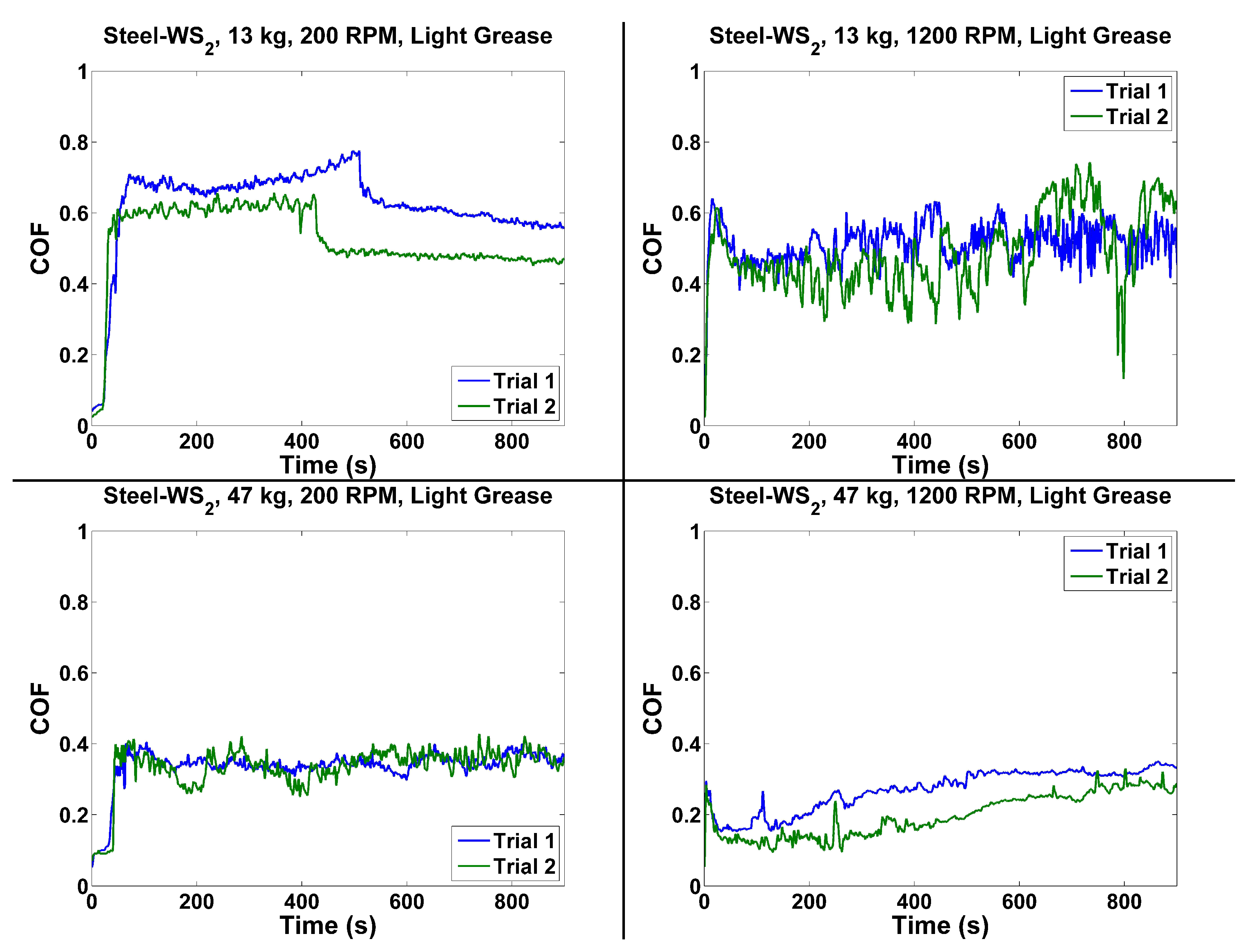
The second series of test utilized the LG configuration steel-on-, utilizing the hard steel ball bearings sold by Falex on top, and using the hard steel ball bearings sold by Falex and later coated with Dicronite as the three ball bearings on the bottom. The test was conducted for loads of 128 N and 461 N, and at speeds of 200 r/min and 1200 r/min. The measured friction is tabulated in Table 2 and plotted in Figure 8.
Just like with the steel–on-steel configuration, these COF results represent the minimum average COF over 60 s for two 15 min trials (first 15 s are discarded). These results are usually but not exclusively the first 15 to 75 s of the 900 s long test. The 128-N-200-r/min and 461-N-1200-r/min pair of tests both have some deviation in friction magnitude, but also exhibit a clear trend in how the friction changes over time with running in, demonstrating that the test is in fact repeatable. It is clearly observed in the data that the COF ratio is observed to decrease (the overall friction force is higher) with the higher speed and the higher load with all-steel ball bearings. These results also show an expected decrease in minimum COF when compared to the same conditions with steel–on-steel, demonstrating that the coating serves to reduce the COF.
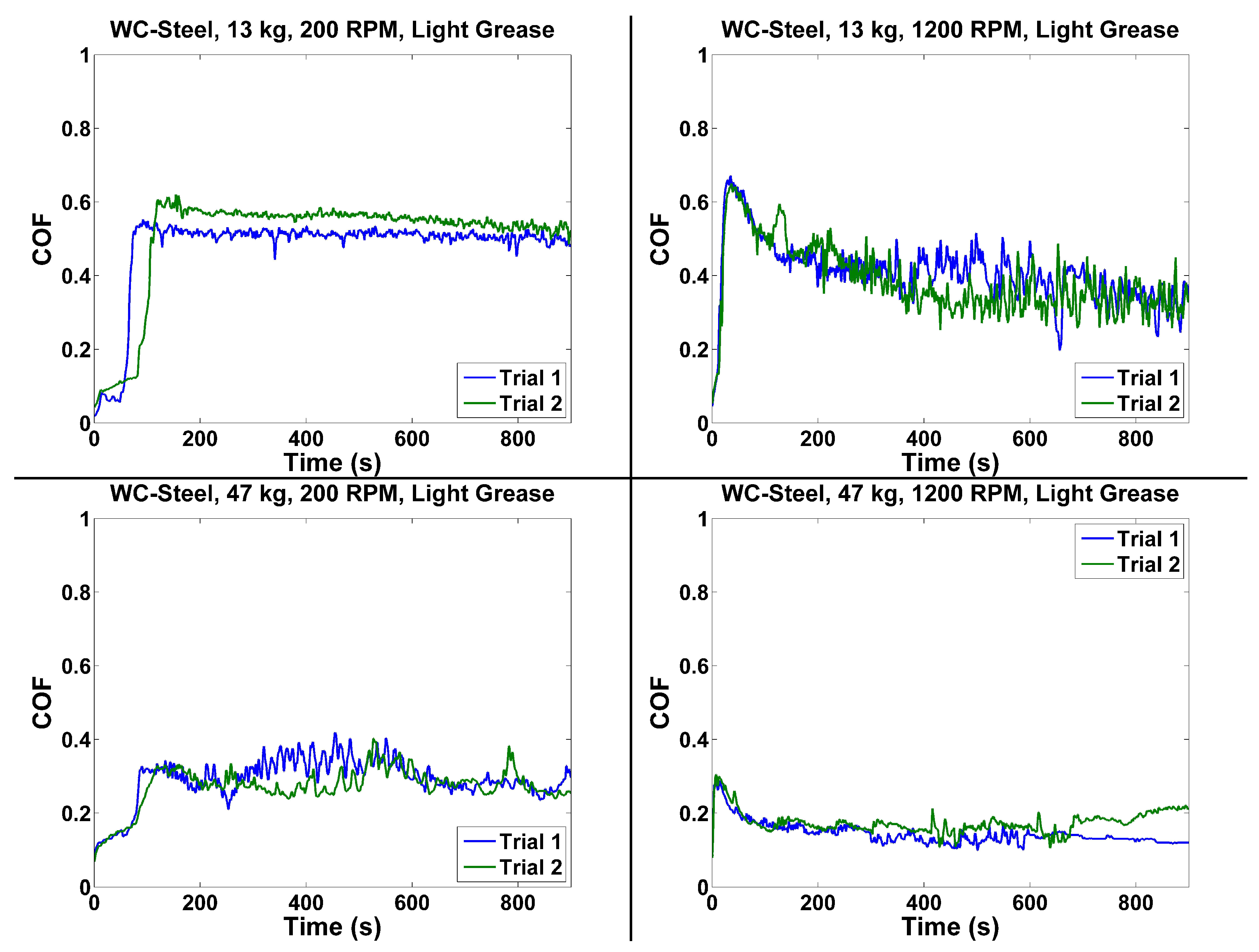
4.3. WC–Steel
The third series of test utilized the LG configuration WC-on-steel, utilizing the tungsten carbide ball bearing sold by VBX on top, and using the hard steel ball bearings sold by Falex on the bottom. The test was conducted for loads of 128 N and 461 N, and at speeds of 200 r/min and 1200 r/min. The measured friction is tabulated in Table 3 and plotted in Figure 9.
Just like with the steel-on-steel and the steel-on- configuration, these COF results represent the minimum average COF over 60 s for two 15 min trials (first 15 s are discarded). It was observed in the 200 r/min cases that the friction was oddly lower when considering the first 300 s; this is believed as due to the lower speed it will take longer than the initial 15 s break-in to have a reasonable amount of wear and surface roughness at the point of contact; therefore it is observed that for 200 r/min trials the minimum possible COF is lower than for 1200 r/min. After 300 s of sliding contact, however, it is clearly observed in the data that the COF ratio is observed to decrease (the overall friction force is higher) with the higher speed and the higher load with all-steel ball bearings.
4.4. WC–
The final stage of the LG study involved a tungsten carbide ball in the spindle and three -coated steel balls on the bottom. The test was conducted for loads of 128 N and 461 N, and at speeds of 200 r/min and 1200 r/min; in addition, speeds of 200 r/min and 1800 r/min were conducted for a load of 981 N. The measured friction is tabulated in Table 4 and plotted in Figure 10.
The phenomenon of a lower COF for 200 r/min with loads and speeds has been observed in the WC– tests for the 128 N and 461 N studies; same as with the WC-Steel tests; the proper trend of lower COF ratio with increasing load and speed is observed after 300 s of contact, when the WC starts to get sufficient surface roughness. This is not observed at the 981 N tests, which has the lowest COF when spun at the high 1800 r/min speed.
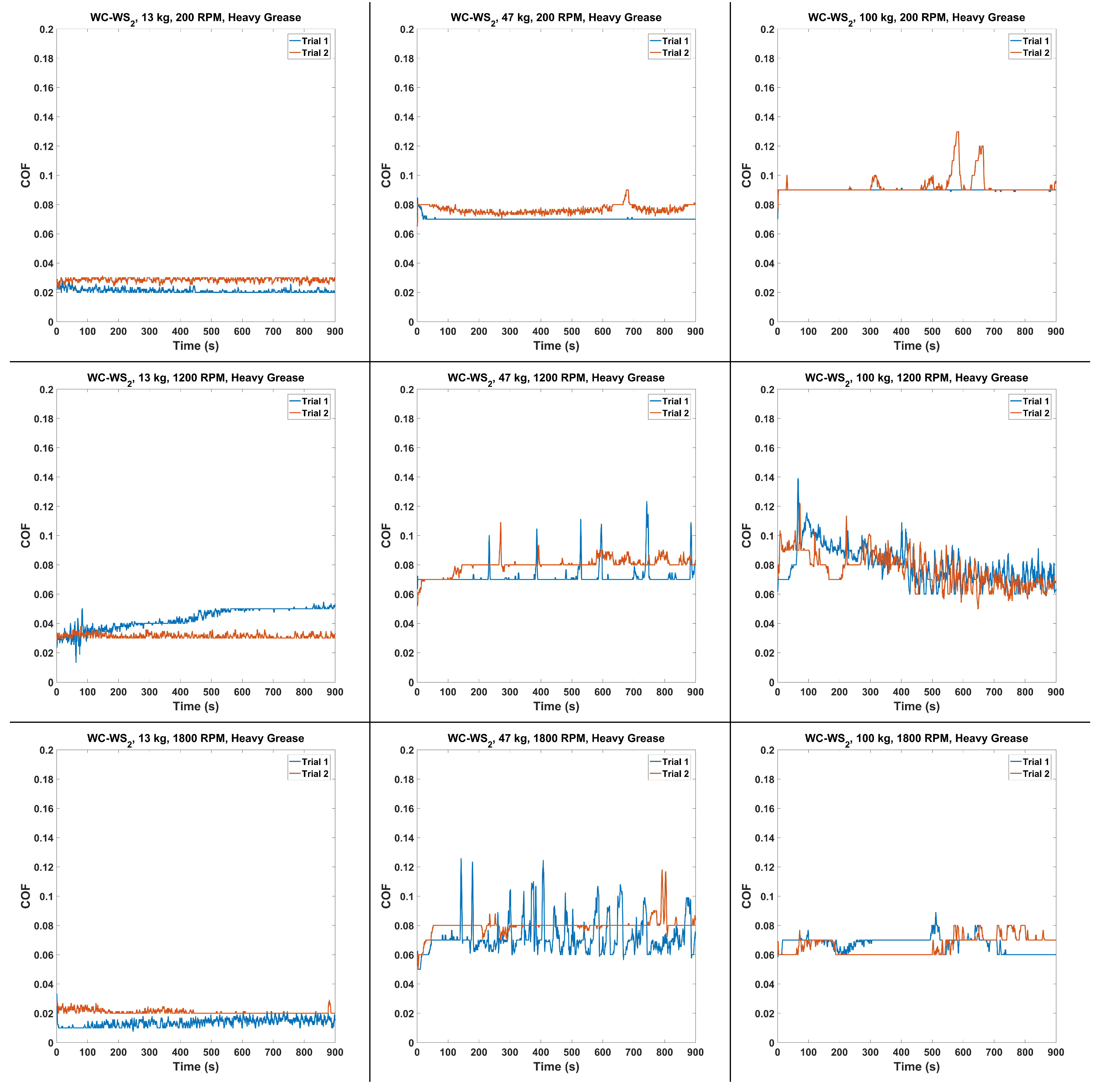
4.5. Heavy Grease WC–
The friction of sliding contact in the presence of heavy Mobilith SHC 460 grease was also studied with the tungsten carbide—tungsten disulfide (WC–) configuration, for loads of 128 N, 461 N, and 981 N, and for speeds of 200 r/min, 1200 r/min, and 1800 r/min. The COF results representing the minimum average COF over 60 s for two 15 min trials (first 15 s are discarded) is tabulated in Table 5 and plotted in Figure 11.
It is clear that the minimum COF ratio is significantly less for heavy grease than for the light grease trials. Also apparent in the qualitative data is the fact that the COF remains relatively consistent during the entire trial; the light grease trials all show an increase in friction (or the friction was high to begin with) from the minimum over time.
5. Optical Profilometer Measurements
After every test, where the sliding friction ran continuously for 900 s, the wear scars were scanned with optical profilometry. Because of the larger wear scars during the LG testing, it was often difficult to measure the complete wear scar without stitching as no wide angle lens was available. As there was no available software to mathematically remove the ball bearing volume and figure out the true surface roughness, each sample received a single scan at the center of the wear scar, whether the entire wear scar was captured or not. While the software was not available to determine the true surface roughness over the entire wear scar, the software did collect the average asperities size over a straight 1D line arbitrarily selected. After each scan, the surface roughness (in m Ra) was collected over an arbitrary line across the wear scar; the line was adjusted to give the maximum surface roughness possible.
The goal of optical profilometry was to confirm that the surface roughness never significantly exceeded 125 RMS (3.175 m average manufacturing finish); an excessive increase in surface roughness will significantly affect the results. A scan of an arbitrary initial ball bearing showed that the initial surface roughness of the ball bearing without a coating to be Ra = 28 nm, and Ra = 36 nm for a coated ball bearing; both of these surface roughness are even smoother than the required Ra = 50.8 nm (2 -inch) required for the G25 bearing standard that is specified for the ASTM D4172 four-ball test. With a total of 67 total four-ball tests (3 balls each for a total of 201 wear scar samples), only 11 had a surface roughness that exceeded Ra = 3.175 m (125 RMS). The average surface roughness was Ra = 1.48 m, and the median was Ra = 1.445 m.
Determining the exact impact of surface roughness to the COF measurements is nearly impossible, though obviously a smoother surface will have a lower COF. It is also noticed that overwhelmingly the minimum minute of COF data is usually within the first 15 s, when the ball bearing is smoothest; the few examples where this trend is not noticed often have a much higher COF. This experimental data on the wear scar surface roughness serves to demonstrate that, in general, the surface roughness of the ball bearings under test were usually smoother than standard manufactures finish of 125 RMS.
6. Conclusions
This effort demonstrated the effectiveness of using both tungsten carbide and tungsten disulfide as a means to reduce the friction during grease-lubricated sliding contact. A parametric study of four ball tests with coated steel ball bearings in sliding contact with a pure WC ball bearing was conducted, with Mobilith SHC 460 PM grease. A clear reduction in the minimum coefficient of friction is observed both by switching to tungsten carbide, as well as by using the coating. The existence of grease can clearly add to the reduction in friction, but in applications where changing the grease is difficult, the dry coating is a viable alternative. The surface friction was continually tracked and was observed to increase as expected over 15 min of run-time. This friction increase was expected to increase with increasing surface roughness from wear; the surface roughness of the samples under test never exceeded an average manufacturer finish of 125 RMS. This effort clearly demonstrated that low friction coefficients under 0.2 are practical with metal in sliding contact and limited grease or oil lubrication.
Funding
This research received no external funding.
Acknowledgments
The authors thank Lou Vocaturo, Kevin Larkins, James McDonnell, Caleb Bonilla, Jeff Ewin, and Jennifer Jensen for useful discussions.
Conflicts of Interest
The founding sponsors had no role in the design of the study; in the collection, analyses, or interpretation of data; in the writing of the manuscript, and in the decision to publish the results.
Abbreviations
The following abbreviations are used in this manuscript:
| COF | Coefficient of Friction |
| HVOF | High Velocity Oxygen Fuel |
| LG | Light-Grease |
| HG | Heavy-Grease |
| ASTM | American Society for Testing and Materials |
| WS | Tungsten Disulfide |
| WC | Tungsten Carbide |
| RMS | Root Mean Square |
| Ra | Roughness Average (Arithmetical Mean Roughness) |
References
- Mudhivarthi, S. Dry Sliding Tribological Characteristics of Hard, Flat Materials with Low Surface Roughness. Master’s Thesis, University of South Florida, Tampa, FL, USA, 2003. [Google Scholar]
- Holmberg, K.; Matthews, A. Coatings Tribology, Properties, Mechanisms, Techniques and Applications in Surface Engineering, 2nd ed.; Elsevier: Amsterdam, The Netherlands, 2009. [Google Scholar]
- Wanstrand, O. Wear Resistant Low Friction Coatings for Machine Elements, Possibilities and Limitations. Ph.D. Thesis, Uppsala University, Uppsala, Sweden, 2000. [Google Scholar]
- Erdemir, A.; Donnet, C. Tribology of diamond-like carbon films: Recent progress and future prospects. J. Phys. D 2006, 39, 311–327. [Google Scholar] [CrossRef]
- Sullivan, J.; Friedmann, T.; Hjort, K. Diamond and amorphous carbon MEMS. Mater. Res. Soc. (MRS) Bull. 2001, 26, 309–311. [Google Scholar] [CrossRef]
- Gupta, B.; Malshe, A.; Bhushan, B.; Subramaniam, V. Friction and wear properties of chemomechanically polished diamond films. J. Tribol. 1994, 116, 445–453. [Google Scholar] [CrossRef]
- Miyoshi, K.; Wu, R.; Garscadden, A.; Barnes, P.; Jackson, H. Friction and wear of plasma deposited diamond films. J. Appl. Phys. 1993, 74, 4446. [Google Scholar] [CrossRef]
- Donnet, C.; Fontaine, J.; Le-Mogne, T.; Belin, M.; Heau, C.; Terrat, J.; Vaux, F.; Pont, G. Diamond-like carbon-based functionally gradient coatings for space tribology. Surf. Coat. Technol. 1999, 120–121, 548–554. [Google Scholar] [CrossRef]
- Scharf, T.; Ohlhausen, J.; Tallant, D.; Prasad, S. Mechanisms of friction in diamond-like nanocomposite coatings. J. Appl. Phys. 2007, 101, 063521-1–063521-11. [Google Scholar] [CrossRef]
- Gardos, M.; Soriano, B. The effect of environment on the tribological properties of polycrystalline diamond films. J. Mater. Res. 1990, 5, 2599–2609. [Google Scholar] [CrossRef]
- Endo, K.; Kotani, S. Observations of Steel Surfaces under Lubricated Wear. Wear 1973, 26, 239–251. [Google Scholar] [CrossRef]
- Nanbu, T.; Yasuda, Y.; Ushijima, K.; Watanabe, J.; Zhu, D. Increase of Traction Coefficient Due to Surface Microtexture. Tribol. Lett. 2008, 29, 105–118. [Google Scholar] [CrossRef]
- Wong, P.; Huang, P.; Wang, W.; Zhang, Z. Effect of geometry change of rough point contact due to lubricated sliding wear on lubrication. Tribol. Lett. 1998, 5, 265–274. [Google Scholar] [CrossRef]
- Saini, B.; Gupta, V.K. Effect of WC/C PVD coating on fatigue behaviour of case carburized SAE8620 steel. Surf. Coat. Technol. 2010, 205, 511–518. [Google Scholar] [CrossRef]
- Abad, M.D.; Munoz-Marquez, M.A.; Mrabet, S.E.; Justo, A.; Sanchez-Lopez, J.C. Tailored synthesis of nanostructured WC/aC coatings by dual magnetron sputtering. Surf. Coat. Technol. 2010, 204, 3490–3500. [Google Scholar] [CrossRef]
- Baragetti, S.; Gerosa, R.; Villa, F. WC/C Coating Protection Effects on 7075-T6 Fatigue Strength in an Aggressive Environment. Procedia Eng. 2014, 74, 33–36. [Google Scholar] [CrossRef] [Green Version]
- Kumar, B.S.; Girish, D. Friction and Wear Behaviour of Tungsten Carbide and E Glass Fibre reinforced Al7075 based Hybrid composites. IOP Publ. Int. Conf. Mater. Manuf. Eng. 2018, 390, 012002. [Google Scholar] [CrossRef]
- Fang, S.; Llanes, L.; Bahre, D. Wear Characterization of Cemented Carbides (WC–CoNi) Processed by Laser Surface Texturing under Abrasive Machining Conditions. Lubricants 2017, 5, 20. [Google Scholar] [CrossRef]
- Fang, S.; Hsu, C.J.; Klein, S.; Llanes, L.; Bahre, D.; Mucklich, F. Influence of Laser Pulse Number on the Ablation of Cemented Tungsten Carbides (WC-CoNi) with Different Grain Size. Lubricants 2018, 6, 11. [Google Scholar] [CrossRef]
- Wu, L.; Guo, X.; Zhang, J. Abrasive Resistant Coatings A Review. Lubricants 2014, 2, 66–89. [Google Scholar] [CrossRef]
- Xu, L.; Song, J.; Zhang, X.; Deng, C.; Liu, M.; Zhou, K. Microstructure and Corrosion Resistance of WC-Based Cermet/Fe-Based Amorphous Alloy Composite Coatings. Coatings 2018, 8, 393. [Google Scholar] [CrossRef]
- Tillmann, W.; Hagen, L.; Luo, W. Process Parameter Settings and Their Effect on Residual Stresses in WC/W2 C Reinforced Iron-Based Arc Sprayed Coatings. Coatings 2017, 7, 125. [Google Scholar] [CrossRef]
- Humphry-Baker, S.; Marshall, J. Structure and Properties of High-Hardness Silicide Coatings on Cemented Carbides for High Temperature Applications. Coatings 2018, 8, 247. [Google Scholar] [CrossRef]
- AMS B Finishes Processes and Fluids Committee. Application of Tungsten Carbide Coatings on Ultra High Strength Steels High Velocity Oxygen/Fuel Process. AMS 2448B; Society of Automotive Engineering (SAE) International: Warrendale, PA, USA, 2004. [Google Scholar]
- Stachowiak, G.; Batchelor, A. Engineering Tribology, 4th ed.; Butterworth-Heinemann: Oxford, UK, 2005. [Google Scholar]
- Hu, Y.; Li, N.; Tønder, K. A Dynamic System Model for Lubricated Sliding Wear and Running-in. J. Tribol. 1991, 113, 499–505. [Google Scholar] [CrossRef]
- Johnson, K. Contact Mechanics; Cambridge University Press: New York, NY, USA, 1987. [Google Scholar]
- Gohar, R. Elastohydrodynamics; World Scientific Publishing Company: Singapore, 2002. [Google Scholar]
- Engineering ToolBox. Friction and Friction Coefficients. 2004. Available online: https://www.engineeringtoolbox.com/friction-coefficients-d_778.html (accessed on 16 August 2018).
- Xu, S.; Gao, X.; Hu, M.; Sun, J.; Jiang, D.; Wang, D.; Zhou, F.; Weng, L.; Liu, W. Dependence of atomic oxygen resistance and the tribological properties on microstructures of WS2 films. Appl. Surf. Sci. 2014, 298, 36–43. [Google Scholar] [CrossRef]
- Xu, S.; Gao, X.; Sun, J.; Hu, M.; Wang, D.; Jiang, D.; Zhou, F.; Weng, L.; Liu, W. Comparative study of moisture corrosion to WS2 and WS2/Cu multilayer films. Surf. Coat. Technol. 2014, 247, 30–38. [Google Scholar] [CrossRef]
- Quan, X.; Hu, M.; Gao, X.; Fu, Y.; Weng, L.; Wang, D.; Jiang, D.; Sun, J. Friction and wear performance of dual lubrication systems combining WS2-MoS2 composite film and low volatility oils under vacuum condition. Tribol. Int. 2016, 99, 57–66. [Google Scholar] [CrossRef]
- Quan, X.; Zhang, S.; Hu, M.; Gao, X.; Jiang, D.; Sun, J. Tribological properties of WS2/MoS2-Ag composite films lubricated with ionic liquids under vacuum conditions. Tribol. Int. 2017, 115, 389–396. [Google Scholar] [CrossRef]
- Maharaj, D.; Bhushan, B. Effect of Mo2 and WS2 Nanotubes on Nanofriction and Wear Reduction in Dry and Liquid Environments. Tribol. Lett. 2013, 49, 323–339. [Google Scholar] [CrossRef]
- Di, Y.; Cai, Z.; Zhang, P. The Tribological Performance of CrMoN/MoS2 Solid Lubrication Coating on a Piston Ring. Lubricants 2017, 5, 13. [Google Scholar] [CrossRef]
- Cann, P.; Spikes, H. In-contact IR spectroscopy of hydrocarbon lubricants. Tribol. Lett. 2005, 19, 289–297. [Google Scholar] [CrossRef]
- Jiang, P.; Li, X.M.; Guo, F.; Chen, J. Interferometry Measurement of Spin Effect on Sliding EHL. Tribol. Lett. 2009, 33, 161–168. [Google Scholar] [CrossRef]
- Reddyhoff, T.; Spikes, H.A.; Olver, A.V. Compression Heating and Cooling in Elastohydrodynamic Contacts. Tribol. Lett. 2009, 36, 69–80. [Google Scholar] [CrossRef]
- Hamrock, B.; Dowson, D. Isothermal Elastohydrodynamic Lubrication of Point Contacts, III Fully Flooded Results. D-8317; Technical Report; NASA: Washington, DC, USA, 1976.
- Ranger, A.; Ettles, C.; Cameron, A. The Solution of the Point Contact Elasto-Hydrodynamic Problem. Proc. R. Soc. Lond. Ser. A Math. Phys. Sci. 1975, 346, 227–244. [Google Scholar] [CrossRef]
- Fillot, N.; Berro, H.; Vergne, P. From Continuous to Molecular Scale in Modelling Elastohydrodynamic Lubrication: Nanoscale Surface Slip Effects on Film Thickness and Friction. Tribol. Lett. 2011, 43, 257–266. [Google Scholar] [CrossRef]
- Guo, F.; Wong, P.L.; Geng, M.; Kaneta, M. Occurrence of Wall Slip in Elastohydrodynamic Lubrication Contacts. Tribol. Lett. 2009, 34, 103–111. [Google Scholar] [CrossRef]
- Krupka, I.; Bair, S.; Kumar, P.; Svoboda, P.; Hartl, M. Mechanical Degradation of the Liquid in an Operating EHL Contact. Tribol. Lett. 2011, 41, 191–197. [Google Scholar] [CrossRef]
- Automotive Lubricating Greases. Available online: https://www.sae.org/standards/content/j310_199004/ (accessed on 16 August 2018).
- Standard Test Method for Wear Preventive Characteristics of Lubricating Fluid (Four-Ball Method). ASTM Int. 2016. [CrossRef]
- Standard Test Method for Measurement of Extreme-Pressure Properties of Lubricating Fluids (Four-Ball Method). ASTM Int. 2014. [CrossRef]
- Marko, M.D.; Kyle, J.P.; Branson, B.; Terrell, E.J. Tribological Improvements of Dispersed Nano-Diamond Additives in Lubricating Mineral Oil. J. Tribol. 2015, 137, 011802. [Google Scholar] [CrossRef]
- Marko, M.D.; Kyle, J.P.; Wang, Y.S.; Branson, B.; Terrell, E.J. Numerical and Experimental Tribological Investigations of Diamond Nanoparticles. J. Tribol. 2016, 138, 032001. [Google Scholar] [CrossRef]
- Marko, M.; Kyle, J.P.; Wang, Y.S.; Terrell, E.J. Tribological investigations of the load, temperature, and time dependence of wear in sliding contact. PLoS ONE 2017, 12. [Google Scholar] [CrossRef]
- Spanu, C.; Ripa, M.; Ciortan, S. Study of Wear Evolution for a Hydraulic Oil Using a Four-Ball Tester. Ann. Univ. Dunareade Jos Galati 2008, 8, 186–189. [Google Scholar]
- DOD-L-85645A. Inclined Plane Test Specification: Lubricant, Dry Thin Film, Molecular Bonded. Available online: http://everyspec.com/DoD/DoD-SPECS/DOD-L-85645A_5698/ (accessed on 16 August 2018).
- Hamrock, B.; Dowson, D. Isothermal Elastohydrodynamic Lubrication of Point Contacts, I Theoretical Formulation. D-8049; Technical Report; NASA: Washington, DC, USA, 1975.
- Hamrock, B.; Dowson, D. Isothermal Elastohydrodynamic Lubrication of Point Contacts, IV Starvation Results. D-8318; Technical Report; NASA: Washington, DC, USA, 1976.
- Dowson, D. Elastohydrodynamic and micro-elastohydrodynamic lubrication. Wear 1995, 190, 125–138. [Google Scholar] [CrossRef]
- Cameron, A.; Gohar, R. Theoretical and Experimental Studies of the Oil Film in Lubricated Point Contact. Proc. R. Soc. Lond. Ser. A Math. Phys. Sci. 1966, 291, 520–536. [Google Scholar] [CrossRef]
- Archard, J. Contact and Rubbing of Flat Surfaces. J. Appl. Phys. 1953, 24, 981–988. [Google Scholar] [CrossRef]
- Greenwood, J.; Williamson, J. Contact of Nominally Flat Surfaces. Proc. R. Soc. Lond. A 1966, 295, 300–319. [Google Scholar] [CrossRef]
- Bush, A.; Gibson, R.; Keogh, G. The Limit of Elastic Deformation in the Contact of Rough Surfaces. Mech. Res. Commun. 1976, 3, 169–174. [Google Scholar] [CrossRef]
- Carbone, G. A slightly corrected Greenwood and Williamson model predicts asymptotic linearity between contact area and load. J. Mech. Phys. Solids 2009, 57, 1093–1102. [Google Scholar] [CrossRef]
- McCool, J. Comparison of Models for the Contact of Rough Surfaces. Wear 1986, 107, 37–60. [Google Scholar] [CrossRef]
- Bush, A.; Gibson, R.; Thomas, T. The Elastic Contact of a Rough Surface. Wear 1975, 35, 87–111. [Google Scholar] [CrossRef]
- Persson, B. Contact mechanics for randomly rough surfaces. Surf. Sci. Rep. 2006, 61, 201–227. [Google Scholar] [CrossRef] [Green Version]
- Golden, J. The Evolution of Asperity Height Distributions of a Surface Seeoed to Wear. Wear 1976, 39, 25–44. [Google Scholar] [CrossRef]
- Bayer, R.; Sirico, J. The Influence of Surface Roughness on Wear. Wear 1975, 35, 251–260. [Google Scholar] [CrossRef]
- Shafia, M.; Eyre, T. The Effect of Surface Topography on the Wear of Steel. Wear 1980, 61, 87–100. [Google Scholar] [CrossRef]
- Marko, M. The Tribological Effects of Lubricating Oil Containing Nanometer-Scale Diamond Particles. Ph.D. Thesis, Columbia University, New York, NY, USA, 2015. [Google Scholar] [CrossRef]
- Blau, P. On the nature of running-in. Tribol. Int. 2005, 38, 1007–1012. [Google Scholar] [CrossRef]
Figure 1.
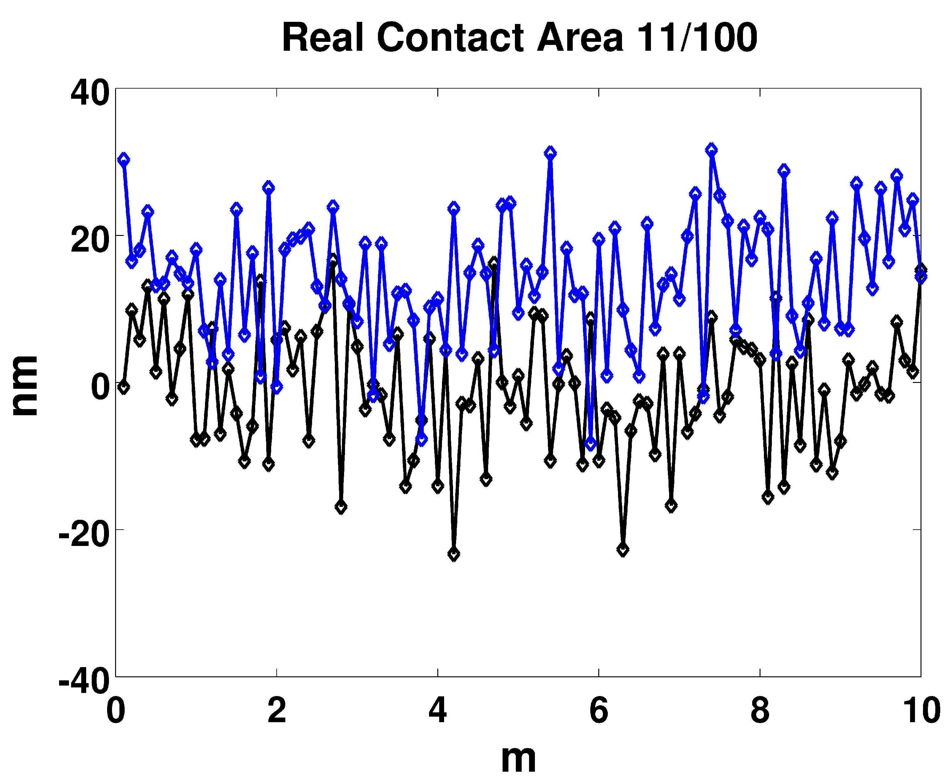
A demonstration of the effect of the true contact area ratio versus apparent contact area. Each of the dots represents a given asperities height, determined with an algorithm to represent such an arbitrary shape [25]. The average asperity height was a nanometer (nm), whereas the average distance separating the surface means was 15 nm. Under these conditions that are typical of smooth, lubricated solid contact, only 11 out of 100 of the top surface asperities contacted the lower asperities, representing the true contact area ratio of 11%.
Figure 1.
A demonstration of the effect of the true contact area ratio versus apparent contact area. Each of the dots represents a given asperities height, determined with an algorithm to represent such an arbitrary shape [25]. The average asperity height was a nanometer (nm), whereas the average distance separating the surface means was 15 nm. Under these conditions that are typical of smooth, lubricated solid contact, only 11 out of 100 of the top surface asperities contacted the lower asperities, representing the true contact area ratio of 11%.

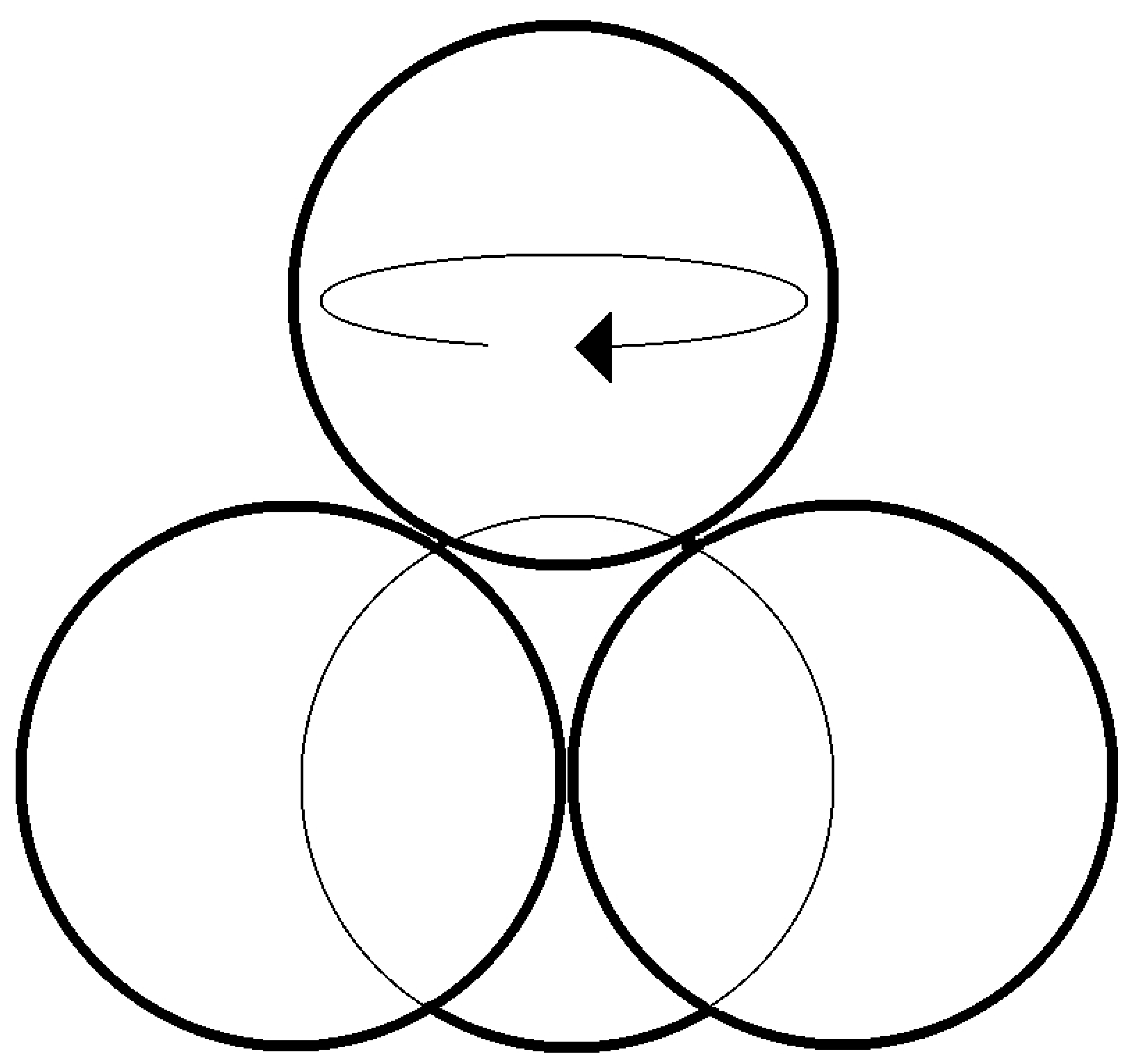
Figure 2.
Four-ball configuration, from ASTM D4172 Standard.

Figure 3.
RMS surface roughness (m) after four-ball test.

Figure 4.
COF of -on-.

Figure 5.
HG vs. LG.

Figure 6.
LG after a test, before cleaning.

Figure 7.
Steel–Steel COF data.

Figure 8.
Steel– COF data.

Figure 9.
WC–Steel COF data.

Figure 10.
WC– COF data.

Figure 11.
WC– Heavy Grease COF data.


Table 1.
Measured Friction, Steel–Steel.
| Grease | Material | Load (N) | Speed (r/min) | COF | COF (900 s) | Scar (mm) |
|---|---|---|---|---|---|---|
| LG | Steel–Steel | 128 | 200 | 0.5787 | 0.65125 | 1.0563 |
| LG | Steel–Steel | 461 | 200 | 0.3212 | 0.4802 | 0.8293 |
| LG | Steel–Steel | 128 | 1200 | 0.3307 | 0.42015 | 1.6949 |
| LG | Steel–Steel | 461 | 1200 | 0.1091 | 0.17155 | 0.9847 |
Table 2.
Measured Friction, Steel–.
| Grease | Material | Load (N) | Speed (r/min) | COF | COF (900 s) | Scar (mm) |
|---|---|---|---|---|---|---|
| LG | Steel– | 128 | 200 | 0.4251 | 0.5832 | 1.0499 |
| LG | Steel– | 461 | 200 | 0.248 | 0.339 | 0.8184 |
| LG | Steel– | 128 | 1200 | 0.3068 | 0.50195 | 1.3511 |
| LG | Steel– | 461 | 1200 | 0.1170 | 0.23415 | 1.2672 |
Table 3.
Measured Friction, WC-Steel.
| Grease | Material | Load (N) | Speed (r/min) | COF | COF (300–900 s) | COF (900 s) | Scar (mm) |
|---|---|---|---|---|---|---|---|
| LG | WC-Steel | 128 | 200 | 0.1052 | 0.4950 | 0.4997 | 0.7089 |
| LG | WC-Steel | 461 | 200 | 0.1427 | 0.2532 | 0.2843 | 0.838 |
| LG | WC-Steel | 128 | 1200 | 0.3166 | 0.3166 | 0.40205 | 1.186 |
| LG | WC-Steel | 461 | 1200 | 0.1176 | 0.1176 | 0.15785 | 1.1885 |
Table 4.
Measured Friction, WC–.
| Grease | Material | Load (N) | Speed (r/min) | COF | COF (300–900 s) | COF (900 s) | Scar (mm) |
|---|---|---|---|---|---|---|---|
| LG | WC– | 128 | 200 | 0.0883 | 0.4075 | 0.47085 | 0.75742 |
| LG | WC– | 128 | 1200 | 0.2189 | 0.2189 | 0.37805 | 0.74092 |
| LG | WC– | 461 | 200 | 0.1355 | 0.2218 | 0.23365 | 1.21125 |
| LG | WC– | 461 | 1200 | 0.1149 | 0.1149 | 0.16895 | 1.4375 |
| LG | WC– | 981 | 200 | 0.1983 | 0.1983 | 0.2429 | 1.0042 |
| LG | WC– | 981 | 1800 | 0.0415 | 0.0415 | 0.0859 | 1.12225 |
Table 5.
Measured Friction, WC–, Heavy Grease.
| Grease | Material | Load (N) | Speed (r/min) | COF | COF (900 s) | Scar (mm) |
|---|---|---|---|---|---|---|
| HG | WC– | 128 | 200 | 0.0201 | 0.02485 | 0.26533 |
| HG | WC– | 128 | 1200 | 0.0301 | 0.0375 | 0.2535 |
| HG | WC– | 128 | 1800 | 0.0101 | 0.0172 | 0.3005 |
| HG | WC– | 461 | 200 | 0.0700 | 0.07325 | 0.419 |
| HG | WC– | 461 | 1200 | 0.0692 | 0.0758 | 0.56125 |
| HG | WC– | 461 | 1800 | 0.0652 | 0.0762 | 0.67375 |
| HG | WC– | 981 | 200 | 0.0899 | 0.06685 | 0.461083 |
| HG | WC– | 981 | 1200 | 0.0646 | 0.09125 | 1.0535 |
| HG | WC– | 981 | 1800 | 0.0600 | 0.07795 | 0.651 |
© 2019 by the author. Licensee MDPI, Basel, Switzerland. This article is an open access article distributed under the terms and conditions of the Creative Commons Attribution (CC BY) license (http://creativecommons.org/licenses/by/4.0/).
Share and Cite
MDPI and ACS Style
Marko, M.D. Friction of Tungsten-Based Coatings of Steel under Sliding Contact. Lubricants 2019, 7, 14. https://doi.org/10.3390/lubricants7020014
AMA Style
Marko MD. Friction of Tungsten-Based Coatings of Steel under Sliding Contact. Lubricants. 2019; 7(2):14. https://doi.org/10.3390/lubricants7020014
Chicago/Turabian StyleMarko, Matthew David. 2019. "Friction of Tungsten-Based Coatings of Steel under Sliding Contact" Lubricants 7, no. 2: 14. https://doi.org/10.3390/lubricants7020014
Note that from the first issue of 2016, this journal uses article numbers instead of page numbers. See further details here.